Loading ...
Loading ...
Loading ...
4
SPECIAL NOTE
After installation or any servicing operation, always ensure that
the appliance is gas sound and that the components are now
operating correctly. Items removed during servicing should be
replaced in the reverse order to their removal.
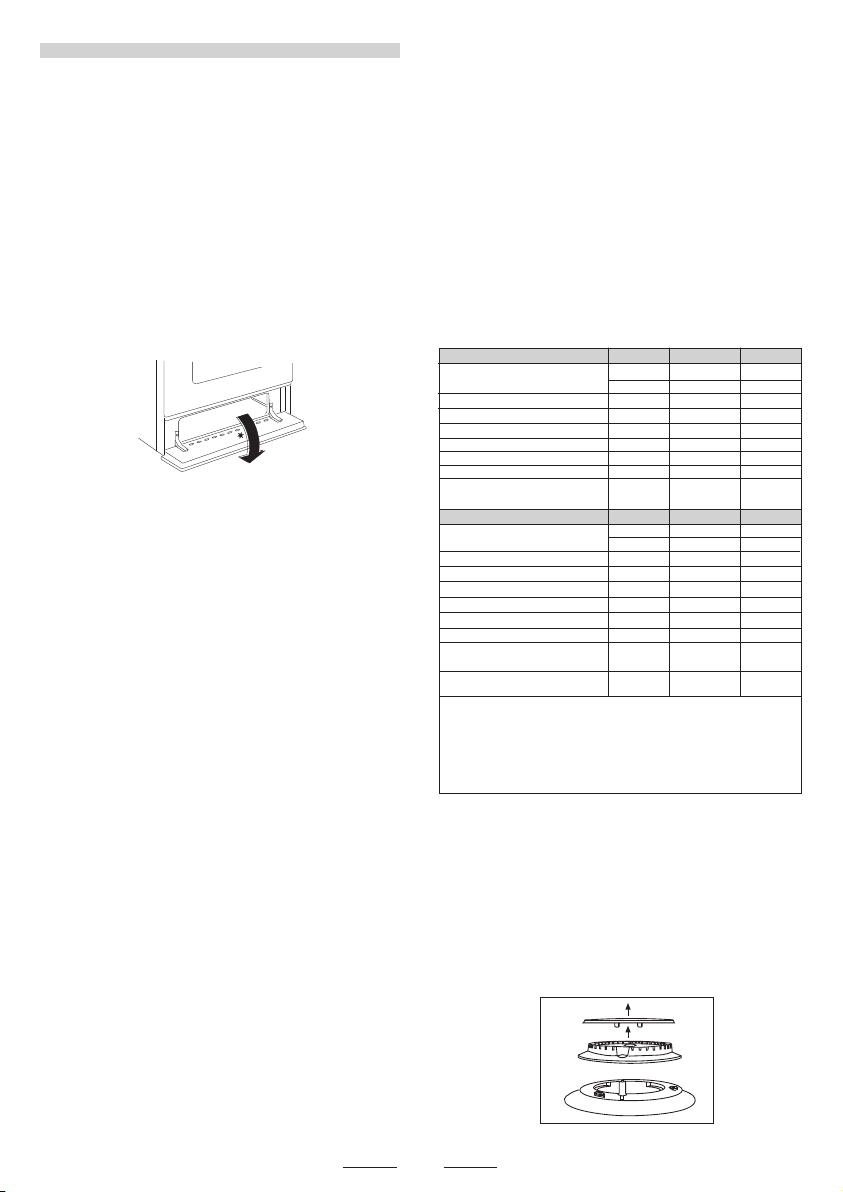
In order to change the work-top injectors, it is necessary to act as
follows:
- remove the grids
- remove burners
and flame-spreaders.
GAS CONNECTION
Should conform to gas utility regulations e.g. AS/NZS
5601 Gas installations; also refer to rangehood
manufacturers recommendations.
Check gas pressure, note the correct setting from the data plate
sealed inside the front appliance drawer .
*
GAS CONVERSION AND ADJUSTMENT
When used with natural gas all burners have been preset at our
factory and further adjustment should not be necessary. C o n version
kits to other gases are available from the place of purchase. D o
not attempt to fit the conversion kit yourself. C onversion to U-LPG
gas should only be carried out by an authorized technician.
GAS ADJUSTEMENTS
- change the injectors
- adjust the minimum flow
‘When converting from Natural Gas to U-LPG ensure that
the NG regulator is removed and replaced with the Test Point
Assembly. A gas regulator suitable for a supply pressure of 2.75kPa
should be part of the gas tank supply and should be adjusted with
the wok burner operating at maximum.
REPLACEMENT OF THE INJECTORS
When required to operate on other gas replace the injectors in
accordance with information referred to in chart below.
This appliance from the factory suitable for NATURAL gas but, if
necessary, can be adjusted for U-LPG by authorised person.
For the adjustments to U-LPG please operate as specified in the
paragraph GAS CONVERSION AND ADJUSTMENT (pag 4).
The Gas Connection is male 1/2" BSP and is situated at the right
hand rear of the appliance, approximately 40mm from the side
and 695mm from the floor (depends on adjustment of feet).
The appliance shall be installed by an authorized person in
accordance with the manufacturer’s installation instructions,
relevant local fitting regulations, municipal building regulations,
the AS/NZS 5601 code for gas burning appliances and
equipment and other relevant statutory code band regulations. If
you have some doubts, please contact the authorities for
confirmation concerning the characteristics of the gas and
electricity output.
The appliance is generally preset for natural gas (so no other
adjustment is necessary) ensure regulator is fitted for N.G.
Ensure that all foreign matter has been cleared from the gas
supply line and also purge all air from the gas system. C on n e ct
to regulator, tighten and check the installation to ensure no gas
leaks occur.
IT IS RECOMMENDED THAT A SERVICE TAP AND UNION BE
FITTED ADJACENT T O THE APPLIANCE INLET TO FACILITATE
FUTURE SERVICING.
5 burner models: set the burner pressure to 1kPa for Natural Gas
and 2.75kPa for U-LPG with the wok burner operating a full rate’.
For commissioning of the appliance with the Oara 97
regulator for Natural Gas, the test point pressure should
be 1.00kPa with all burners operating on HIGH.
Apply a manometer to the test nipple and reset the regulator if
necessary. Do not forget to replace the test nipple screw and to
leave the instructions book with the user.
VERY IMPORTANT FOR THE INSTALLER
Do not attempt to turn or stress threaded elbow of the manifold:
you risk damage to this part of the gas appliance which may void
the manufacturers warranty.
Before Leaving - Check all connections for gas leaks with soap
and water. DO NOT use a naked flame for detecting leaks. Ignite
all burners to ensure correct operation of gas valves, burners and
ignition. Turn gas taps to low flame position and observe stability
of the flame.
When satisfied with the cooker, please instruct the user on the
correct method of operation.
In case the appliance fails to operate correctly after all checks
have been carried out, refer to the authorised service provider in
your area.’
This appliance can be connected with rigid pipe as specified in
AS/NZS 5601 table 3.1 or with an AGA approved, Class B or D
flexible hose with 10mm I.D. and 1.2m max. length in
accordance with AS/NZS 5601 for a 'high level connection'.
The hose should not be subjected to abrasion, kinking or permanent
deformation and should be able to be inspected along its entire
length. Unions compatible with the hose fittings must be used and
connections tested for gas leaks. The fixed consumer piping outlet
should be at approximately the same height as the cooker
connection point, pointing downwards and approximately 150mm
to the side of the cooker.
The hose should be clear of the floor when the cooker is in the
installed position.
Ensure that the chain prevents stress on the hose assembly when
the cooker is moved out of its normal operating position.
TAB. 1
Natural Gas 1.00 kPa
0.90 Auxiliary 4.0
1.20 Semi-rapid
7.1
1.50 Rapid 11.0
U - LPG 2.75 kPa
0.53
Auxiliary 3.7
0.73 Semi-rapid 7.0
0.95
Rapid 11.7
NG Regulator
LP Test point
adaptor
Regulator
-
with GC & GE & GP & GL & GU pan supports
1.35 Rapid 9.1
with YP pan supports
-
0.87 Rapid 10.2
Jet mm Ø Burners Po
wer MJ/h
Jet mm Ø Burners Power MJ/h
with GC & GE & GP & GL & YP & GU
pan supports
NOTE:
GE = Enameled Steel pan supports
GL = Light Cast Iron pan supports
YP = Light Cast Iron pan supports (evolution)
GP = Heavy Cast Iron pan supports
GC = Flat heavy cast iron pan supports
GU = Flat heavy cast iron pan supports
1.00 TC 1 12.7
1.63 TC1 12.7
with GC & GE & GP & GL & YP & GU
pan supports
-
-
with GC & GE & GP & GL & GU pan supports
with YP pan supports
-
-
with GC & GE & GP & GL & YP & GU
pan supports
with GC & GE & GP & GL & YP & GU
pan supports
Loading ...
Loading ...
Loading ...