Loading ...
Loading ...
Loading ...
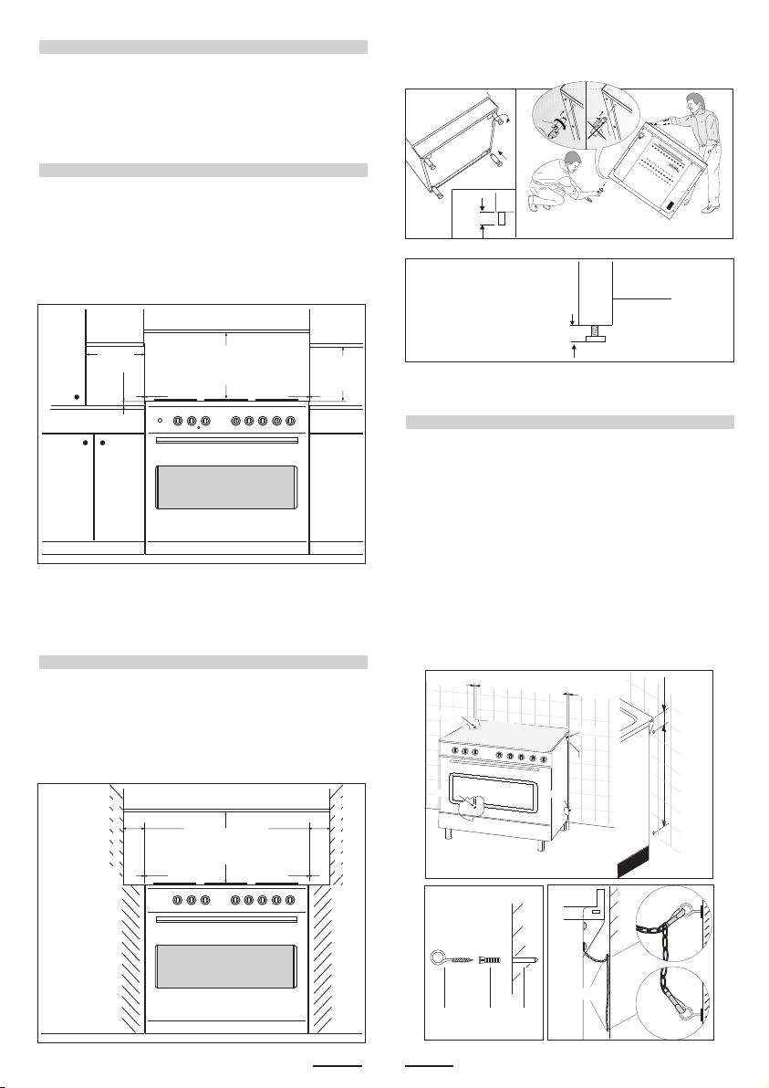
POSITIONING
Important: Fix the chain located next to the gas connection on
both sides of the cooker to the wall to prevent the cooker from
tilting. Both chains must be securely fixed.
Make sure that the wall surface behind the Cooker is non-
combustable (will not catch fire).
Where a painted surface is adjacent, a fire retardent paint surface
is recommended. Wallpaper, wood, or fabric should not be used
behind or next to the cooker.
“Any adjoining wall surface (side or rear) situated within 200mm of
any hob burner must be a suitable non-combustible material
from the edge for a height of 150mm for the entire length of
the cooker.
Any combustible construction above the cooker must be at least
650mm above the maintop.” Ensure that a power and gas supply
are nearby. The Cooker should be located carefully so that the
heat produced by it has plenty of space to escape. The diagram
below shows an ideal configuration.
Note:
The cooker is fitted with 4 legs for an eventual alignment in height
with the furniture ( fig. 1 A or 1 B according to the models ).
3
min.100 mm
min. 650 mm
min. 400 mm
"0" mm "0" mm
REG.
MAX
160mm
REG. MAX 15mm
Clearances to combustible materials
No part of any adjoining wall surface can be made of combustible
materials. The protection of combustible materials
required by Clause 5.12.1.1 of AS/NZS 5601 is the fixing of 5 mm
thick ceramic tiles to the surface or attaching fire resistant
material to the surface and covering with sheet metal with a minimum
thickness of 0.4 mm.
Clearances to non- combustible materials
min. 650 mm
"0" mm "0" mm
min "60" mmmin "60" mm min "60" mm
non- combustible materials
non- combustible materials
“If the cooker is being fitted next to cupboards or adjoing wall
surfaces, which are within 200mm from the edge of the hob
burner and of a suitable non-combustible material as specified
in AS/NZS 5601, then ensure that a distance of at least 6cm
is left between the edge of the cooker and the
non-combustible material. This gap is to allow plenty of
space for the heat produced by the cooker to escape on
each side of the cooker.
min.10 mm
TO FIX THE COOKER TO THE REAR WALL
WARNING - For safety reasons and to prevent tipping of the appliance,
these stabilizing means must be installed.
The cooker is equipped with 2 chains fixed on each side at the rear of
the cooker near the top (see Fig. A). The chains are fitted with “spring
clips” which must be clipped to the “screw eyes” provided with the cooker.
Install the “screw eyes” as follows :
1. Drill four 6mm holes (position 1 - 2 - 3 - 4) in the wall
as in Fig. A.
2. Insert part “R” into the holes then screw in the “screw eyes” part
“G” see Fig. B.
Note: If the part provided is not suitable for the wall material please
use an appropriate device to ensure secure holding of the “screw
eyes” to the wall.
3. Bring the cooker near the wall and clip the chains on the
“screw eyes” as in Fig. C.
IMPORTANT: If the cooker is moved for any reason
(e.g. maintenance) resulting in the cooker being unclipped from the
wall, the cooker must be re-clipped to the wall at the completion of
the task.
If the cooker is placed on a base, measures have to be taken to prevent
it from slipping off the base
.
OK NO
Fig. 1 A
Fig. 1 B
Fig. B
Fig. C
G
wall
wall
Fig. A
76 mm550 mm
G R Hole
55 mm
chain
Position
1
Position
2
55 mm
Position
3
Position
4
Loading ...
Loading ...
Loading ...