Loading ...
Loading ...
Loading ...
4
2 1/8" (5.4 cm)
3/8"
(1.0 cm)
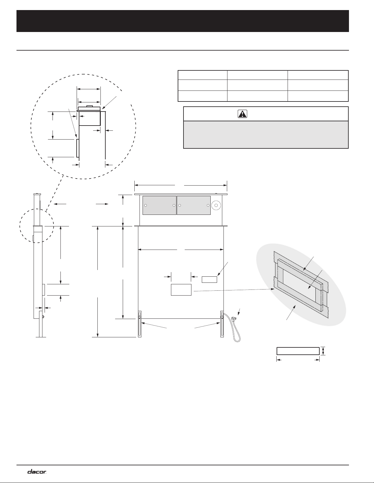
Product Specifications
30 1/4"
(76.8 cm)
to
37 1/4"
(94.6 cm)
10"
(25.4 cm)
30"
(76.2 cm)
18 5/8”
(47.3 cm)
5/16” (8 mm)
thick stiffener
across back
3 3/4"
(9.5 cm)
1"
(2.5 cm)
28" 3-prong
grounded
power cord
Vent shown
in raised
position
Product
data label
Motor
cover
Front of unit
6"
(15.2 cm)
2 9/16"
(6.5 cm)
9/16"
(1.4 cm)
2 1/2"
(6.4 cm)
1 15/16"
(4.9 cm)
B
A
Adjustable
anchor legs
2 1/8"
(5.4 cm)
2 3/16"
(5.6 cm)
3/16"
(5 mm)
Top cap with
vent down
Tolerances: ±1/16” (±1.6 mm) unless otherwise stated
See Pg. 9 for exhaust
locations/dimensions.
*Max height of downdraft
must not exceed cooking
unit
’s max. specified counter
height. (See cooking unit’s
installation instructions.)
*
Product Dimensions: HRV46, MRV48
Model No.
A - Top-Cap Width B - Chassis Width
HRV46
46” (116.8 cm) 43 3/8” (110.2 cm)
MRV48 48” (121.9 cm) 43 3/8” (110.2 cm)
HRV, MRV top cap (side view)
IMPORTANT
INSTALLER: To ensure the cooking unit performs properly, seal
all seams around the motor cover where it contacts the vent
chassis with aluminum tape. (See the graphic below for motor
cover location.)
Aluminum tape
Motor cover
Vent chassis
Loading ...
Loading ...
Loading ...