Loading ...
Loading ...
Loading ...
12
Installation Preparation
Verifying Package Contents
1. Unpack the unit, and verify that all items on the parts list
are present. Notify your dealer immediately if anything is
missing. Do not install a damaged or incomplete appli-
ance. The customer must report cosmetic issues within
30 days of installation.
Parts List
• Product literature
• Anchoring legs (left - PN 36861, right - PN 36862)
• 2 wood screws, #14 x 2 1/2 (PN 83047)
• 3 wire nuts
• 1
5
/8 x 16 to 3 ¼ x 10 duct transition (PN 13768)
• 2 sheet metal screws, #10 x 1/2 (PN 83022)
• 2 keps nuts, 1/4-20 (PN 83049)
• 2 flat washers, 1/4-20 (PN 83203)
• Insulation foam (tape)
Installation with CABP3 blower requires Dacor adapter kit
# AERVCAB. Kit includes adapter, wiring diagram label
(PN 106770), 3 wing nuts (PN 83035), 3 flat washers (PN
83008) and 6 lock washers (PN83340).
WARNING
• If the electrical outlet does not meet the Electrical
Specifications on Pg. 2, postpone the installation
until a licensed electrician install the proper outlet.
• Install the vent vertically only.
• Do not enlarge or modify the exhaust knock-outs. Cut
an exhaust hole on the chassis only as shown to pre-
vent an increase in noise and compromised function.
NOTE: The downdraft vent installs in the back of the cut-
out, separate from the range or cooktop. Install the down-
draft vent before installing the range or cooktop.
2. Start by loosely attaching the anchoring legs to the
studs on the left and right sides of the downdraft vent
using the provided Keps nuts and washers.
Installation Preparation: Downdraft Vent
With ILHSF-/REMP-Series Blower
NOTE: For units using the CABP3 cabinet blower, skip to
Installation Preparation for Downdraft Vent with CABP3
Cabinet Blower, on facing page.
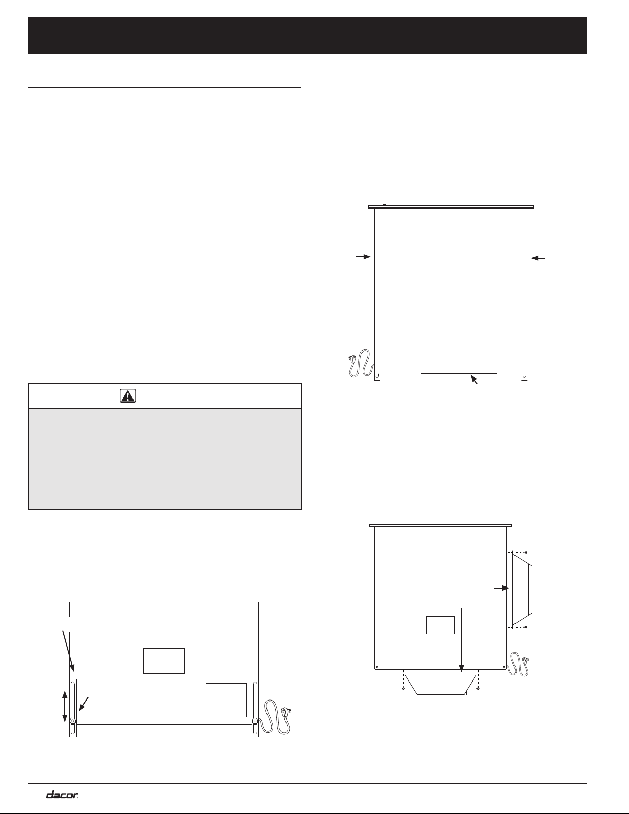
1. Remove the appropriate
side or bottom exhaust
knockout (depending on the desired exhaust configu-
ration) from the downdraft vent chassis by cutting the
metal cross overs and removing the insert.
2. Cut and remove the foil material inside the knock-out
hole or the vent will not work.
• If the unit will vent through the bottom or side, install
the suppled 1
5
/8 x 16 to 3¼ x 10 transition to the
exhaust location. Before installing, peel the protective
backing off the foam tape, and apply it to the transition
flanges. Attach the transition with the provided sheet
metal screws (see below).
• If the unit will vent through the back, attach a 3 ¼
x 10 duct to the vent hole created by removing the
knock-out on the back of the unit.
3. See Installing the Downdraft Vent in the Cutout, Pg.
13.
Installation Instructions
Back of unit
Side
knock-out
Side
knock-out
Bottom knock-out
Put nuts/
washers on
studs
Front of unit
Anchor leg
Transition side
installation
Transition bottom
installation
Attach sealing
foam
Loading ...
Loading ...
Loading ...