Loading ...
Loading ...
Loading ...
26 27
Figure 12
INSTALLATION GUIDE
INSTALLATION GUIDE
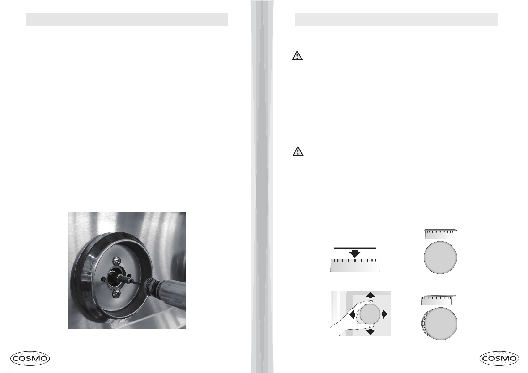
STEP 3: MINIMUM FLAME ADJUSTMENT
These adjustments should be made only for use of the
appliance with natural gas. For use with liquid propane gas, the
choke screw must be fully turned in a clockwise direction.
a.
Light one burner at a time and set the knob to the MINIMUM
position (small flame).
b.
Remove the knob.
c.
The range is equipped with a safety valve. Using a small-
size slotted screwdriver, locate the choke valve on the valve
body and turn the choke screw to the right or left until the
burner flame is adjusted to desired minimum.
d.
Make sure that the flame does not go out when switching
quickly from the MAXIMUM to the MINIMUM position when
knob is re-installed.
PLACEMENT OF COOKTOP BURNERS AND GRATES
Do not operat
e the surface burners without all burner parts in place.
1.
Position surface burner heads on top of the surface burner
bases as shown at right. The electrodes will fit into the slot in
the bottom of the heads. Make sure the surface burner heads
are flat and parallel with the cooktop.
2.
Place the matching size caps on top of each surface burner
head.
CAUTION
3.
Place the left, center, and right surface burner grates on the
cooktop. The edges of the grates should match up with the porcelain
edges of the cooktop.
To prevent flare-ups and avoid creation of harmful by-products, do not
use the cooktop without all burner caps properly installed to insure proper
ignition and gas flame size.
Alway
s
keep the burner caps and burner heads in place whenever the
surface burners are in use. Do not allow spills, food, cleaning
agents or any other material to enter the gas orifice holder
openings.
Check and be sure the size of each burner cap matches the size of the
burner head. Check and be sure that all round style burner caps are
correctly in place on round burner heads.
CA
UTION
Burner cap lip
Burner cap
Correct burner cap placement
Incorrect burner cap placement
Loading ...
Loading ...
Loading ...