Loading ...
Loading ...
Loading ...
•Before making the connection, make sure that the installation is
protected by a suitable fuse, see table, and that it is fitted with
wires of a large enough section to supply the appliance normally.
•Turn over the hob, glass side against the work top, taking care to
protect the glass.
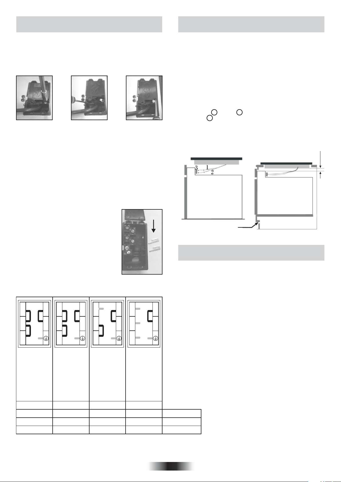
•Open the cover in the following sequence;
5.3 WIRING AND SAFETY OF THE BUILT-IN
COMBINED OVEN
Figure 17 Figure 18 Figure 19
• Unscrew the cable clamp “1”,
• Find the two tabs located on the sides,
• Put the blade of a flat screw-driver in front of each tab “2” e “3”,
push in and press,
• Remove the cover.
To release the power supplying cord.
• Remove the screws retaining the terminal block which contains
the shunt bars and the conductors of the supply cord,
• Pull out the supply cord.
•Operations to be carried out to make a mew connection:
-Choose the power supply cable in accordance with the
recommendations in the table.
-Pass the power supply cable in to the clamp.
-Strip the end of each conductor of the supply
cord on a 10 mm length, by taking in account
the requested length of the cord for the
connection to the terminal block.
-According to the installation and with the help
of shunt bars which you should have recovered
in the first operation, fix the conductor as
shown on the chart.
-Fix the cover.
-Screw the cable clamp.
Note: make sure the terminal board screws are
tight.
Shunt
Connection to the electrical circuit, on the oven or glass ceramic
hob, should be made via the oven.
The ceramic hob without controls, has been developed to be used
only in conjunction with specific separate control units or built in
ovens with integral hob controls.
A detailed table (supplied with ovens with integral hob control or
with independent control units) shows clearly how the hobs are to
be connected to the specified units.
Under no circumstances must the hob be connected with any
other control or oven not specified in the list.
To proceed with the connection, it is necessary to joint male
connectors 1 and 2 of the hob with the “female”
connectors 3 of the oven or of the control panel.
5.4 VITROCERAMIC HOB WITHOUT
CONTROL KNOB
550x10
22 mini
Bult-in oven "apertures" : Refer to
instructon booklet concerned.
the
OVEN
HOB
INSTALLATION WITH OVEN
This connection can be made before or after the oven is
screwed into place.
Figure 22
L1: Phase
shunt 1-2 and
shunt 2-3
N: Neutral
shunt 4-5
T: Earth
L1: Phase
shunt 1-2 and
shunt 2-3
L2: Phase
shunt 4-5
T: Earth
L1: Phase
shunt 1-2
L2: Phase
shunt 3
L3: Phase
shunt 4-5
T: Earth
L1: Phase
L2: Phase
L3: Phase
N: Neutral
shunt 4-5
T: Earth
Figure 20
Figure 21
09 GB
MONOPHASE TWO-PHASE THREE-PHASE THREE-PHASE
VOLTAGE
CABLE-SECTION
CABLE-TYPE
220 - 240 V~ 220 - 240 V2~ 220 - 240 V3~ 380 - 415 V3N~
2
3 G 2.5 mm
2
3 G 2.5 mm
2
4 G 1.5 mm
2
5 G 1.5 mm
HO5VV-F HO5VV-F HO5VV-F HO5VV-F
3
2
1
4
5
3
2
1
4
5
3
2
1
4
5
3
2
1
4
5
Loading ...
Loading ...
Loading ...