Version 09/12 - Page 1
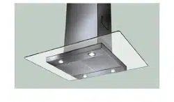
MATRIX
(with LED read out display)
Wall Mount Luxury Rangehood
READ AND SAVE THESE INSTRUCTIONS
READ THESE INSTRUCTIONS BEFORE YOU START INSTALLING THIS RANGEHOOD
WARNING: - TO REDUCE THE RISK OF A RANGE TOP GREASE FIRE: a) Never leave surface units unattended at high
settings. Boilovers cause smoking and greasy spillovers that may ignite. Heat oils slowly on low or medium setting. b)
Always turn hood ON when cooking at high heat or when ambeing food (i.e. Crepes Suzette, Cherries Jubilee, Pepper-
corn Beef Flambé). c) Clean ventilating fans frequently. Grease should not be allowed to accumulate on fan or lter. d)
Use proper pan size. Always use cookware appropriate for the size of the surface element.
WARNING: - TO REDUCE THE RISK OF INJURY TO PERSONS IN THE EVENT OF A RANGE TOP GREASE FIRE, OBSERVE
THE FOLLOWING: SMOTHER FLAMES with a close-tting lid, cookie sheet, or metal tray, then turn off the burner. BE
CAREFUL TO PREVENT BURNS. If the ames do not go out immediately EVACUATE AND CALL THE FIRE DEPARTMENT.
NEVER PICK UP A FLAMING PAN - You may be burned. DO NOT USE WATER, including wet dishcloths or towels - a
violent steam explosion will result. Use an extinguisher ONLY if: 1. You know you have a Class ABC extinguisher, and
you already know how to operate it. 2. The re is small and contained in the area where it started. 3. The re department
is being called. 4. You can ght the re with your back to an exit.
LISEZ BIEN CETTE FICHE AVANT D'INSTALLER LA HOTTE
AVERTISSEMENT - POUR MINIMISER LE RISQUE D’UN FEU DE GRAISSE SUR LA TABLE DE CUISSON : a) Ne jamais laisser
un élément de la table de cuisson fonctionner sans surveillance à la puissance de chauffage maximale; un renversement/
débordement de matière graisseuse pourrait provoquer une inammation et le génération de fumée. Utiliser toujours une
puissance de chauffage moyenne ou basse pour le chauffage d’huile. b) Veiller à toujours faire fonctionner le ventilateur
de la hotte lors d’une cuisson avec une puissance de chauffage élevée ou lors de la cuisson d’un mets à amber (i.e.
Crepes Suzette, Cherries Jubilee, Peppercorn Beef Flambé). c) Nettoyer fréquemment les ventilateurs d’extraction. Veiller
à ne pas laisser de la graisse s’accumuler sur les surfaces du ventilateur ou des ltres. d) Utiliser toujours un ustensile
de taille appropriée. Utiliser toujours un ustensile de taille adapté à la taille de l’élément chauffant.
AVERTISSEMENT: - POUR PRÉVENIR LES BLESSURES EN CAS DE FEU SUIVRE LES RECOMMANDATIONS SUIVANTES:
ÉTOUFFEZ LE FEU avec un couvercle métallique et fermez le brûleur. Si le feu ne s'éteint pas tout de suite, QUITTEZ
LES LIEUX ET APPELEZ LES POMPIERS. NE TOUCHEZ JAMAIS UNE CASSEROLE EN FLAMMES. N'UTILISEZ JAMAIS
DE L'EAU ou un torchon mouillé pour éteindre le feu - ce qui pourrait causer une explosion de vapeur. N'utilisez un
extincteur que si: 1. Vous avez un modèle ABC et vous connaissez bien son mode d'emploi. 2. Le feu est petit et peu
répandu. 3. Les pompiers sont déjà prévenus. 4. Vous avez une sortie derrière vous.

Version 09/12 - Page 2
VENTING REQUIREMENTS
Flexible ductwork is not recommended. If it is used,
each foot of exible ductwork used is equivalent to
two feet of straight metal ductwork when calculating
the ductrun length. Thus, a exible elbow equals two
standard elbows.
WARNING - To Reduce The Risk Of Fire, Use Only Metal
Ductwork.
ELECTRICAL REQUIREMENTS
-
WARNING - TO REDUCE THE RISK OF FIRE OR ELECTRIC
SHOCK, do not use this fan with any solid-state speed
control device.
WARNING - TO REDUCE THE RISK OF FIRE, ELECTRI-
CAL SHOCK, OR INJURY TO PERSONS, OBSERVE THE
FOLLOWING: Use this unit only in the manner intended
by the manufacturer. If you have any questions, contact
the manufacturer.
Before servicing or cleaning unit, switch power off at
service panel and lock the service disconnecting means
to prevent power from being switched on accidentally.
When the service disconnecting means cannot be locked,
securely fasten a prominent warning device, such as a
tag, to the service panel.
CAUTION: For General Ventilating Use Only. Do Not
Use To Exhaust Hazardous or Explosive Materials and
Vapors.
WARNING - TO REDUCE THE RISK OF FIRE, ELECTRI-
CAL SHOCK, OR INJURY TO PERSONS, OBSERVE THE
FOLLOWING: Installation Work And Electrical Wiring Must
Be Done By Qualied Person(s) In Accordance With All
Applicable Codes And Standards, Including Fire-Rated
Construction.
Sufcient air is needed for proper combustion and
exhausting of gases through the ue (chimney) of fuel
burning equipment to prevent backdrafting. Follow the
heating equipment manufacturer's guideline and safety
standards such as those published by the National Fire
Protection Association (NFPA), and the American Society
for Heating, Refrigeration and Air Conditioning Engineers
(ASHRAE), and the local code authorities.
When cutting or drilling into wall or ceiling, do not dam-
age electrical wiring and other hidden utilities.
Ducted fans must always be vented to the outdoors.
WARNING
WARNING
For residential use only.
!
!
Cold Weather installations

RÈGLEMENTS D'ÉVACUATION
Utilisez un tuyau d'évacuation rigide lorsque possible.
Un tuyau exible égale deux fois plus qu'un tuyau rigide,
ce qui réduit la puissance d'évacuation.
AVERTISSEMENT - Pour Ne Pas Risquer Un Feu, Utilisez
Seulement Les Matériaux Métalliques.
AVERTISSEMENT - POUR RÉDUIRE LE RISQUE
D'INCENDIE OU DE CHOC ELECTRIQUE, ne pas utiliser
ce ventilateur en conjonction avec un dispositif de réglage
de vitesse à semi-conducteurs.
AVERTISSEMENT – POUR MINIMISER LES RISQUES
D’INCENDIE, CHOC ÉLECTRIQUE OU DOMMAGES
CORPORELS, OBSERVER LES PRESCRIPTIONS
SUIVANTES: Suivez les recommandations du fabricant
et entre en communication avec lui pour toute
information.
Fermez le courant avant tout entretien et veillez a ce qu'il
reste fermé. Si on ne peut pas verrouiller le panneaux
du service électrique, afchez un avis de danger sur la
porte.
AVIS: Pour L'évacuation Générale - Veillez à Ne Pas
Evacuer Des Matériaux Ou Vapeurs Explosif.
AVERTISSEMENT – POUR MINIMISER LES RISQUES
D’INCENDIE, CHOC ÉLECTRIQUE OU DOMMAGES
CORPORELS, OBSERVER LES PRESCRIPTIONS
SUIVANTES: L'installation Et Le Raccordement Electrique
Doivent Se Faire Par Un Technicien Qualié Selon Tous
Les Codes Municipaux.
An d'obtenir un rendement maximal en ce qui a trait à la
combustion ainsi qu'à l'évacuation des gaz par la conduite
de cheminée, une bonne aération est nécessaire pour
tous les appareils à combustion. Suivez les conseils et
mesures de sécurité du fournisseur tels que ceux publiés
par l'Association Nationale de la Sauvegarde contre
l'Incendie et l'Association Américaine d'Ingénieurs de
Chauffage, Frigorifaction et Air Climatisé ainsi que les
codes municipaux.
En perçant un mur veillez à ne pas perforer un autre l
électrique.
Une ventilateur à évacuation extérieure doit être
raccordée à l'extérieur.
AVERTISSEMENT
FICHE TECHNIQUE ÉLECTRIQUE
AVERTISSEMENT
Uniquement pour usage menager.
!
!
Installations pour régions à climat froid
For best results, use no more than three 90° elbows. Make sure that
there is a minimum of 24" of straight duct between elbows if more than
one is used. Do not install two elbows together. If you must elbow right
away, do it as far away from the hood's exhaust opening as possible.
FIGURE 3FIGURE 2
PLAN THE INSTALLATION
Charcoal Filter
WARNING!
WARNING
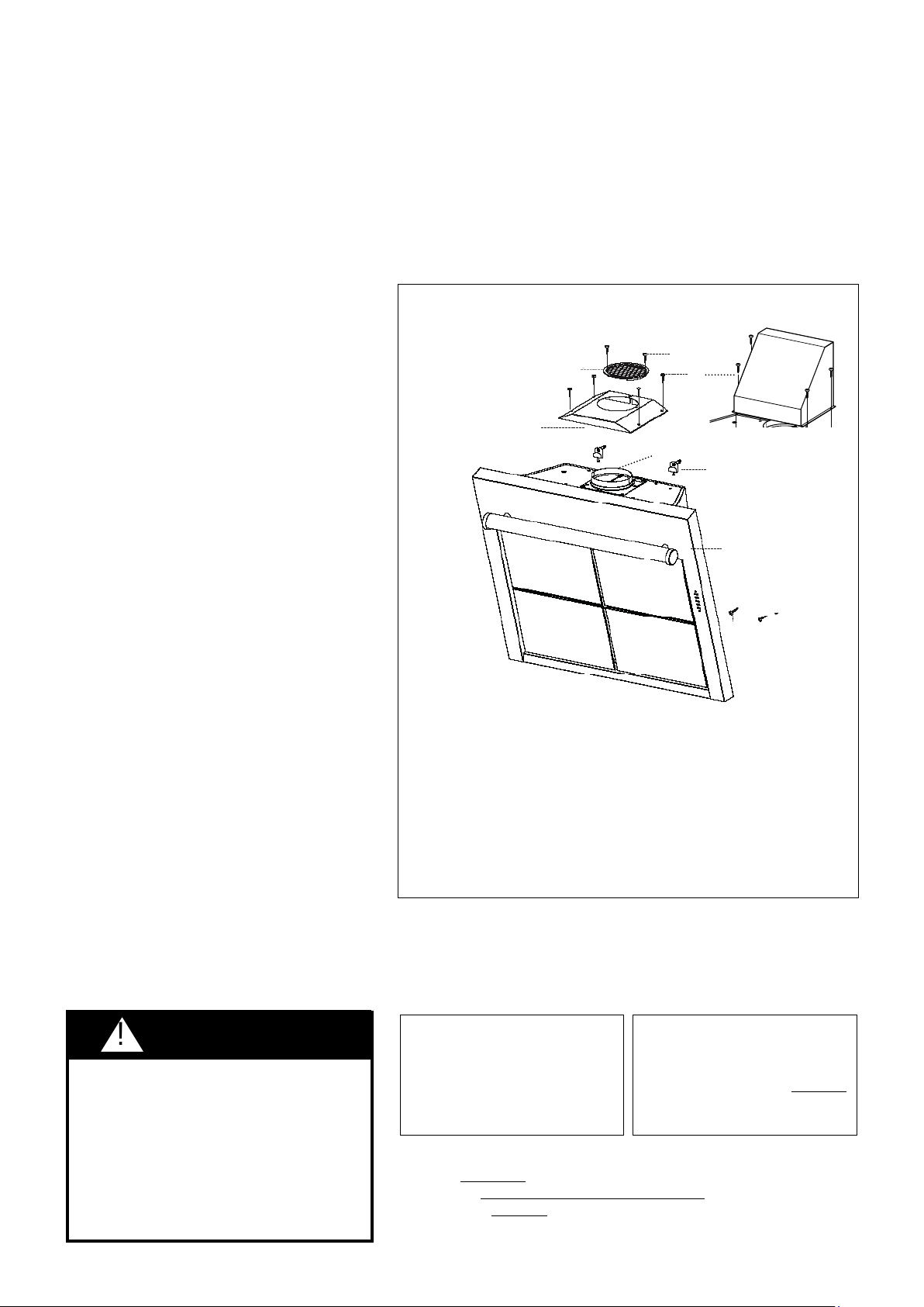
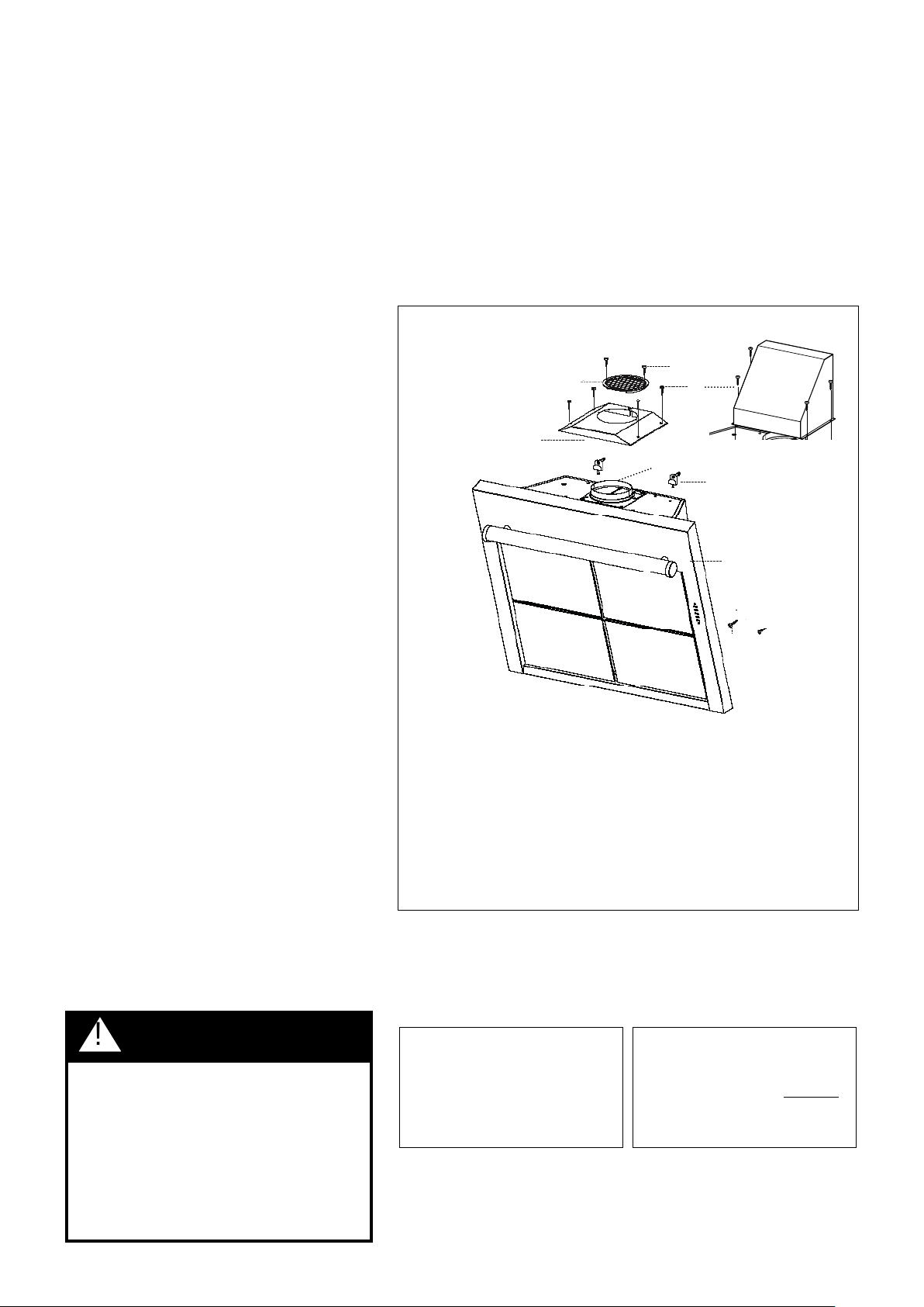
FIGURE 1
A. CANOPY SECTION
B. MOUNTING BRACKETS WITH SCREWS
C. DUCTLESS GRILLE
D. REAR DUCTING CHIMNEY TRANSITION
E. CHIMNEY / VENT SCREWS
F. SAFETY SCREWS
G. GRILLE COVER
H. GRILLE COVER SCREWS
I. DAMPER
!
A
B
C
D
E
F
F
G
H
I
TOOLS NEEDED FOR INSTALLATION
PARTS SUPPLIED FOR INSTALLATION
PARTS NEEDED FOR INSTALLATION
OPTIONAL ACCESSORIES AVAILABLE
Replacement Charcoal Filter
• Optional Chimney Cover
WARNING
CALCULATE THE DUCTRUN LENGTH
FIGURE 2
FIGURE 3
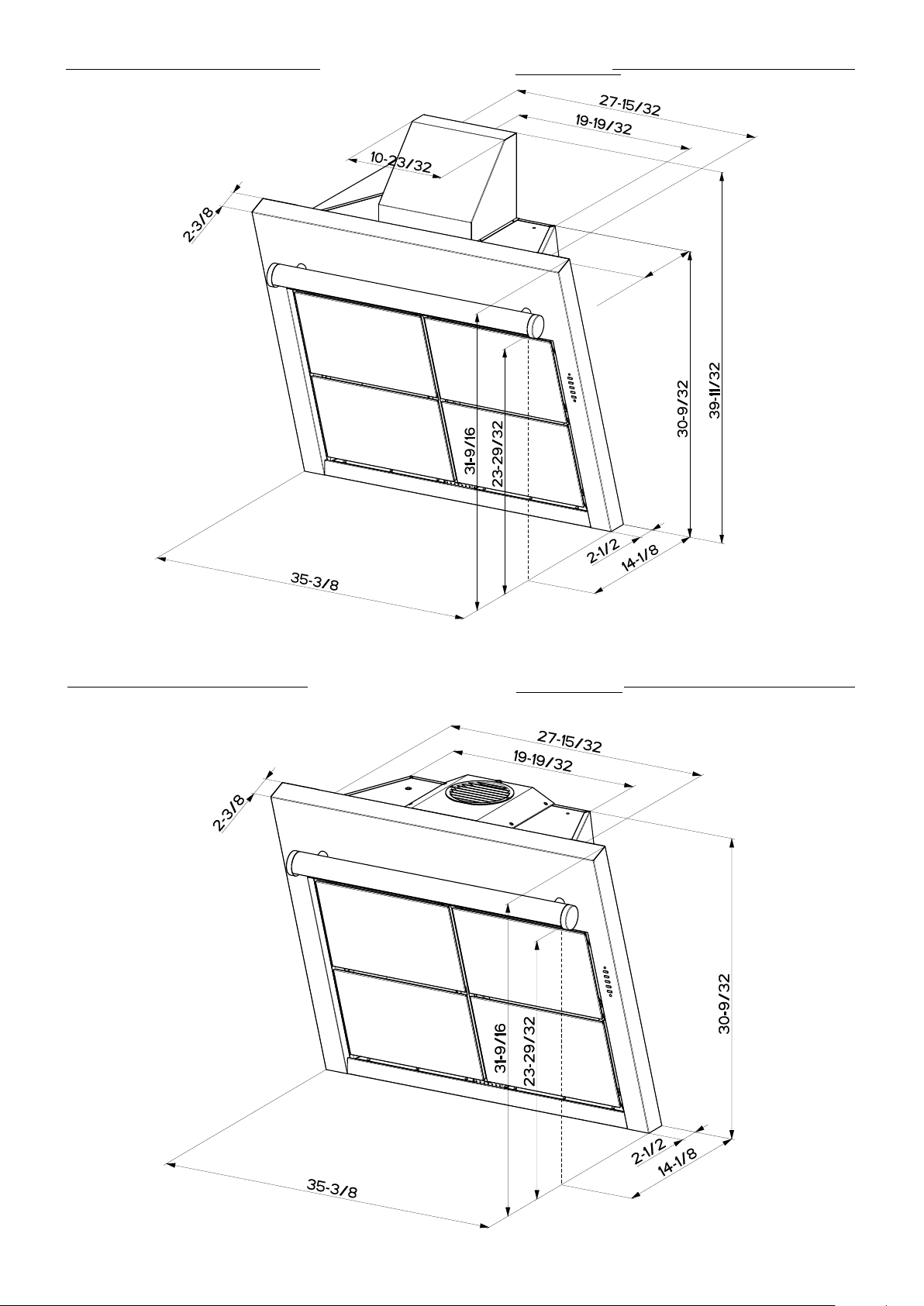
RANGEHOOD COMPONENTS
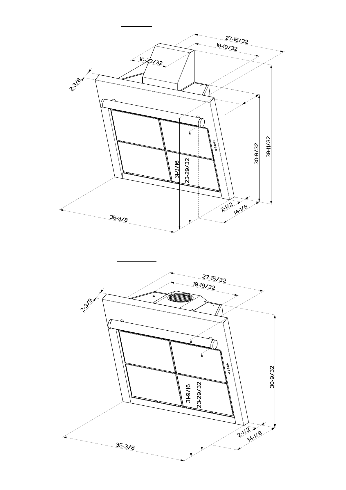
DUCTED INSTALLATION DIMENSIONS
(vented to the outside)
11”
DUCTLESS INSTALLATION DIMENSIONS
(not vented to the outside)
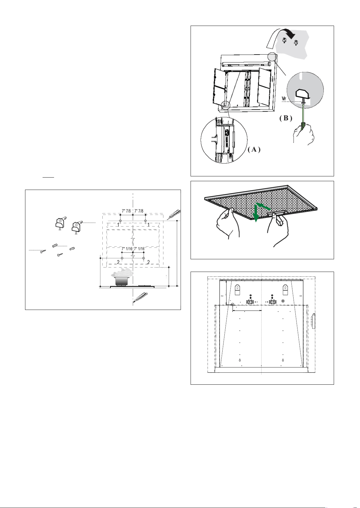
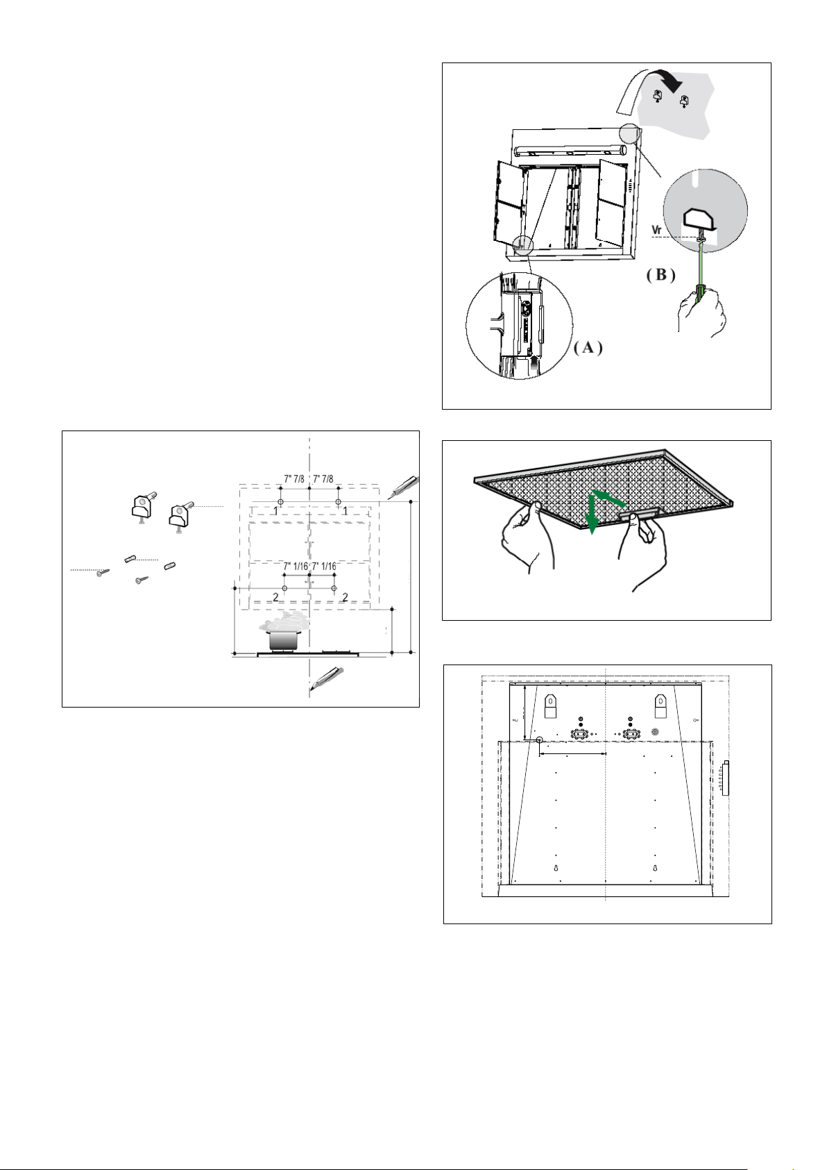
PREPARE THE WALL
1. -
2.
3. (as indicated
in FIGURE 4). (in FIGURE 4)
(in FIGURE 4)
FIGURE 5
5.(in FIGURE 4)
(in FIGURE 4)
B
F
G
FIGURE 4
INSTALL THE RANGEHOOD
1. -
(as indicated in (A)
FIGURE 5).
(FIGURE 6)
(B in
FIGURE 5)
(B in FIGURE 5)
(Hole 2, in FIGURE 4)
6. (I in FIGURE 1) -
FIGURE 6
FOR ALL INSTALLATIONS
1.
FIGURE
7
WARNING: THE SCREWS PROVIDED FOR MOUNTING THIS
RANGEHOOD MUST BE INSERTED INTO SOLID WOOD. THESE
MUST NOT BE INSERTED INTO SHEET ROCK.
15"
19 7/16"
43"
FIGURE 7
7 7/8"
9
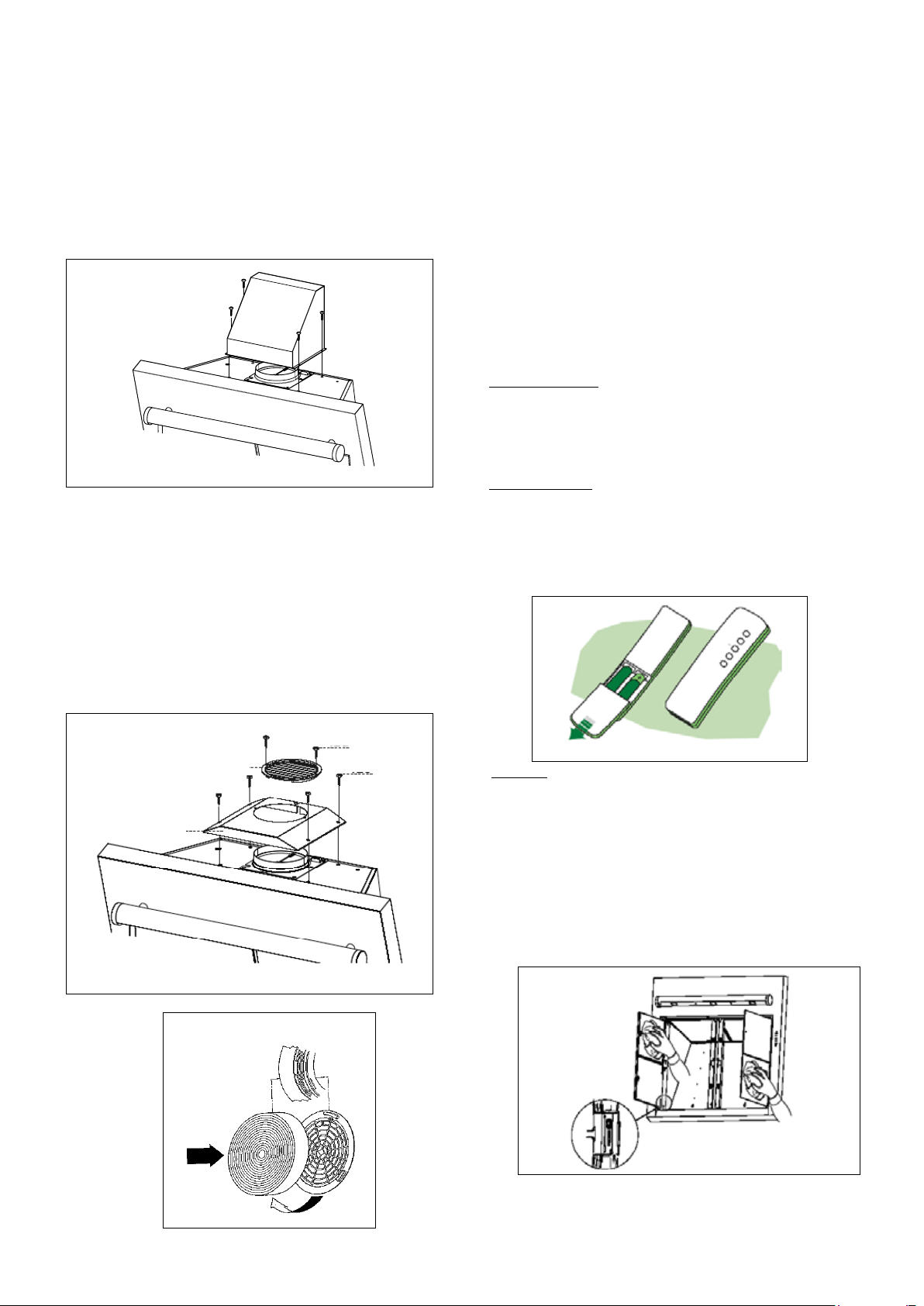
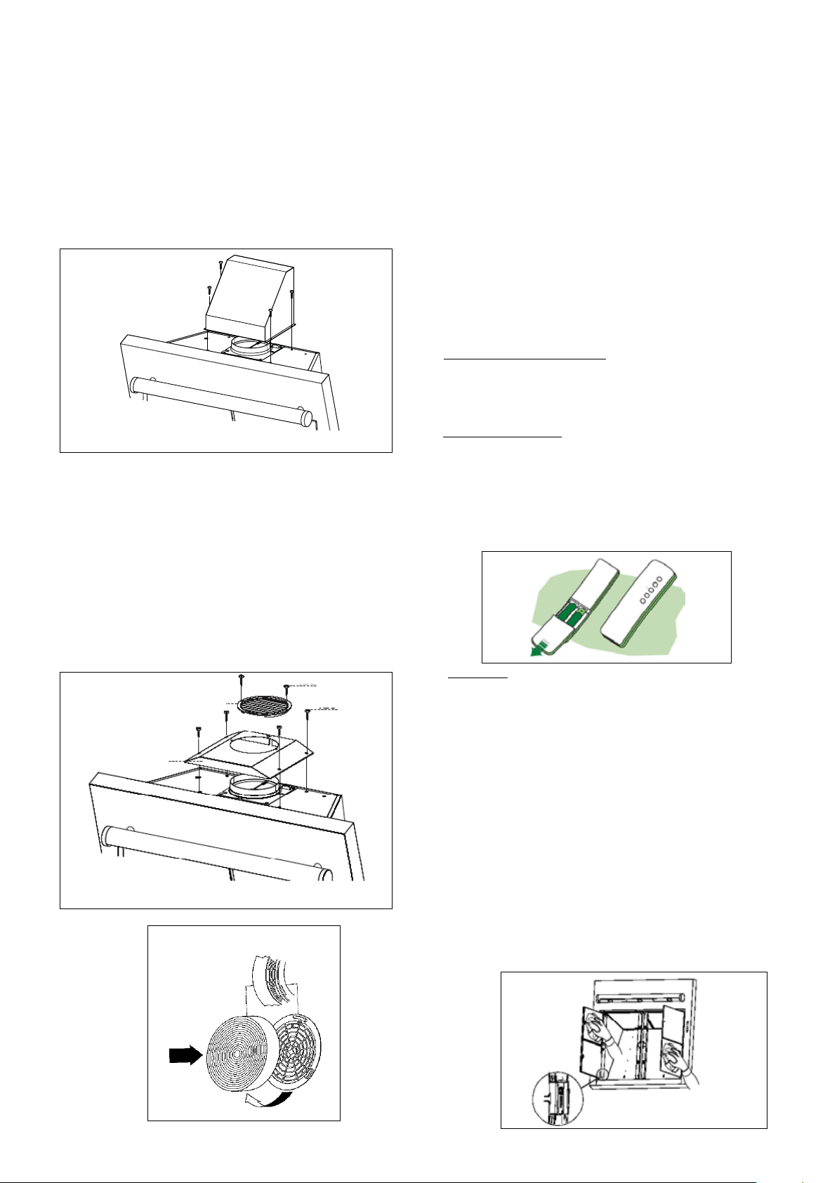
DUCTED INSTALLATIONS
FIGURE 8
1.
(FIGURE 8)
FIGURE 9
C
E
H
I
DUCTLESS INSTALLATIONS
1.
(part C using the E screws in FIGURE 9)
H in FIGURE 9
(I in FIGURE 9).
(as indicated in FIGURE 10).
FOR ALL INSTALLATIONS
1. (as indicated in FIGURE 6)
(as indicated in FIGURE 5)
FIGURE 10
USE AND CARE INFORMATION
For Best Results
Remote Control
(indicated in FIGURE 14 on
the next page).
(as indicated in FIGURE 11).
Do not place the remote control close to heat sources.
FIGURE 11
Cleaning
(FIGURE 12)
FIGURE 12
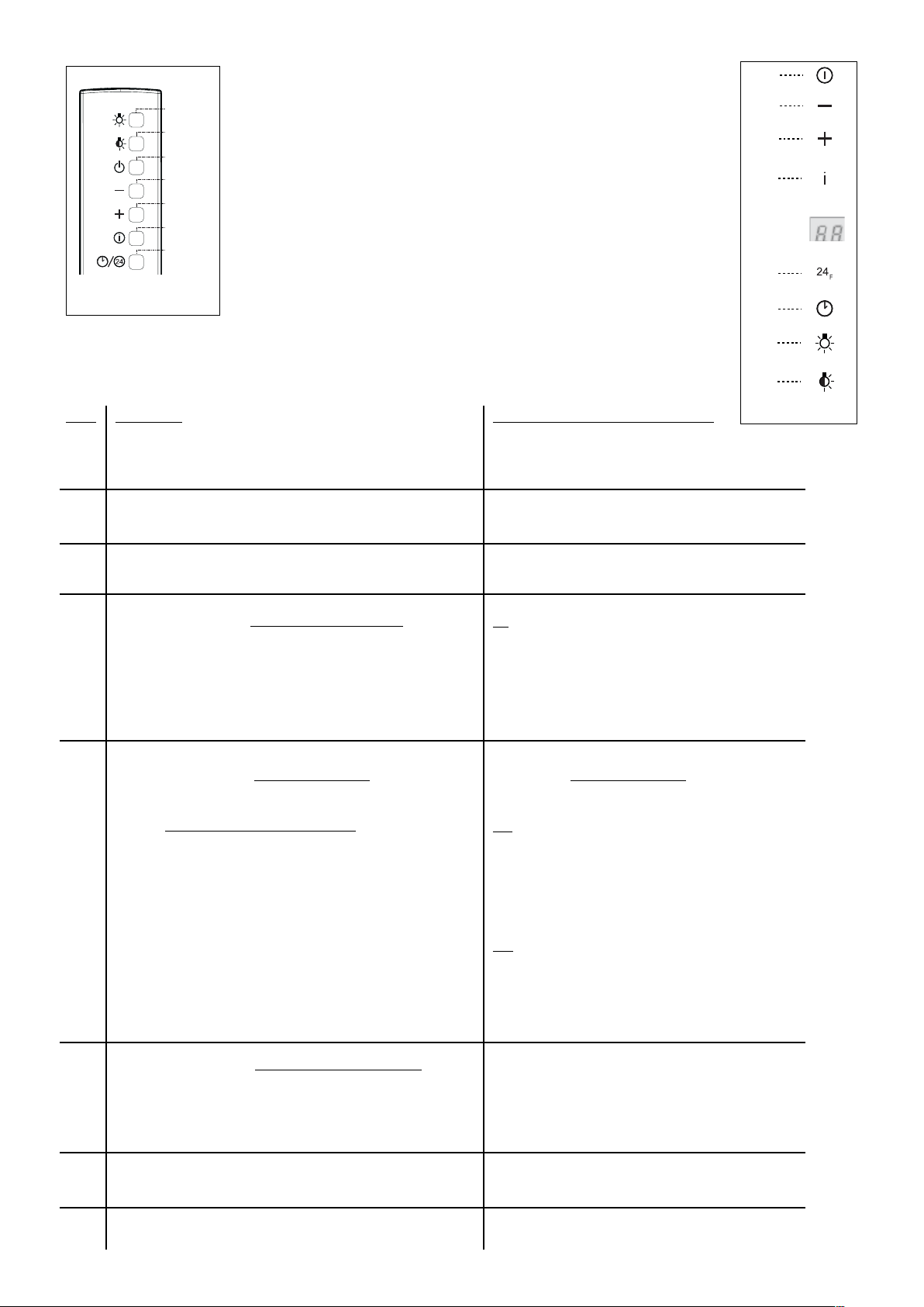
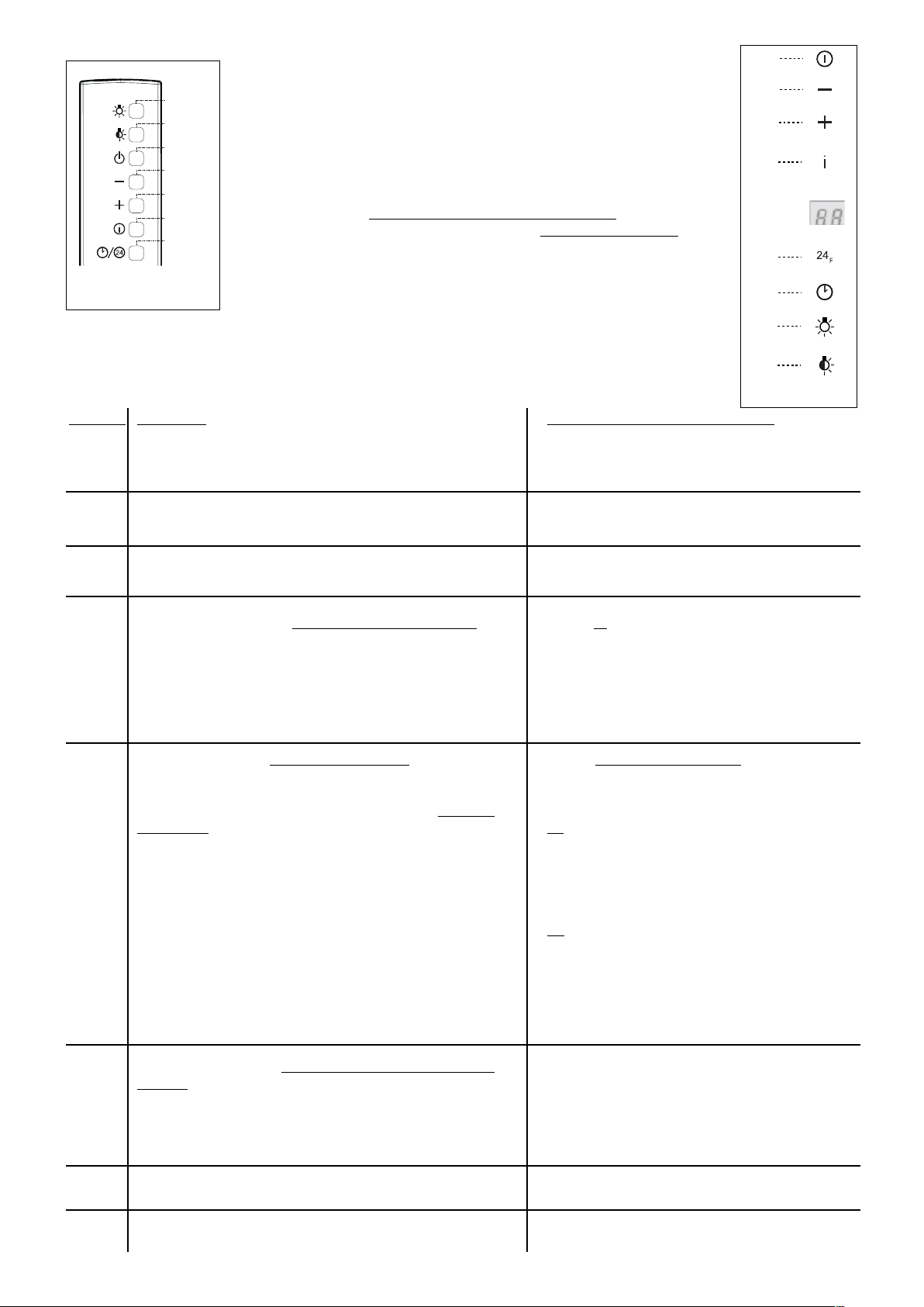
USE AND CARE CONTINUED - CONTROL PANEL
FIGURE 13
FIGURE 14
FIGURE 13
Key
A
D
E
F
Function
intensive boost function
24 hr - function
refresh and clean your home
30 minute delay shutdown
Related LED Display Symbol
HI
24 hr - function
FF
See
the next page for instructions on
resetting the alarm
EF
See the next page for
instructions on resetting the alarm
A
B
C
D
E
F
G
H
LED
T1 T2 T3 T4 T5 T6 T7
IT
Accende e
spegne
líimpianto
di illumina-
zione.
Accende e
spegne
líimpianto di
illuminazione
ad intensit‡
ridotta.
Accende e spe-
gne il motore di
aspirazione
allíultima velocit‡
utilizzata.
Decrementa
la velocit‡ di
esercizio.
Incrementa
la velocit‡ di
esercizio.
Attiva la velocit‡ intensiva da qualsiasi velocit‡ anche da
motore spento, tale velocit‡ Ë temporizzata a 10 minuti, al
termine del tempo il sistema ritorna alla velocit‡ precedente-
mente impostata. Adatta a fronteggiare le massime emissioni
di fumi di cottura.
- Attiva lo spegnimento automatico ritardato di 30í. Adatto per completare
líeliminazione di odori residui. Attivabile da qualsiasi posizione, si disattiva
premendo il tasto o spegnendo il motore.
- Premendo per circa 2î il tasto,attiva il motore ad una velocit‡ che consente
uníaspirazione di 100 m3/h per 10 minuti ogni ora, terminati il motore si
ferma.
GB
Turns light
on and off .
Turns light on
and off at
reduced
intensity.
Switches the
extractor motor on
and off at the
latest selected
speed
Decreases
the suction
speed.
Increases
the suction
speed.
By pressing this key it is possible to activate the intensive
speed from any previously selected speed. The intensive
speed can be activated even when the motor is OFF. This
speed has been timed at 10 minutes. After that time the sys-
tem activates automatically the latest selected speed. This
function is suitable for cooking conditions when vapours and
smells are of the utmost emission.
- By pressing this key it is possible to set the delayed shutdown of the ap-
pliance to 30 minutes. This function is suitable for a complete elimination of
the residual smells. It can be activated at any position, and it is deactivated
by pressing the key again or by switching off the motor.
- Press the button for approximately 2", it is possible to set up the motor to a
suction speed at 100 m
3
/h lasting 10 minutes every hour. After this the
motor switches off automatically.
FR
Allume et
Èteint
líÈclairage.
Allume et
Èteint
líÈclairage ‡
intensitÈ
rÈduite.
Allume et Èteint le
moteur
díaspiration ‡ la
derniËre vitesse
utilisÈe
Diminue la
vitesse de
service
Augmente la
vitesse de
service
Active la vitesse intensive ‡ partir de níimporte quelle vitesse,
mÍ me du moteur arrÍ tÈ. Cette vitesse est programmÈe pour
durer 10 minutes, aprËs quoi le systËme retourne ‡ la vitesse
rÈglÈe au prÈalable. Sert ‡ faire face ‡ une quantitÈ maximale
de fumÈes de cuisson.
- Active líarrÍ t automatique retardÈ de 30 minutes. Utile pour achever
díÈliminer toute odeur rÈsiduelle. Síactive depuis toutes les positions et se
dÈsactive en appuyant sur la touche ou en Èteignant le moteur.
- En appuyant pendant 2" environ sur la touche, active le moteur ‡ une
vitesse permettant une aspiration de 100 m
3
/h pendant 10 minutes toutes
les heures, puis le moteur síarrÍ te.
DE
Schaltet die
Beleuchtun
g ein oder
aus.
Schaltet die
verminderte
Beleuchtung
ein oder aus.
Schaltet den
Motor der
Absauganlage bei
der zuletzt
verwendeten
Geschwindigkeit
ein und aus.
Vermindert
die
Betriebsges
chwindigkeit
.
Erhˆht die
Betriebsges
chwindigkeit
.
Aktiviert von jeder Geschwindigkeit aus, auch bei abgestelltem
Motor, die Intensivgeschwindigkeit, die auf 10 Minuten
zeitgeregelt ist. Nach Ablauf dieser Zeit kehrt das System zu
der zuvor eingestellten Geschwindigkeit zur¸ck. F¸ r die
Beseitigung von sehr intensiven Kochd¸nsten geeignet.
- Aktiviert das automatische Ausschalten mit einer Verzˆgerung von 30 Min.
Ermˆglicht die Beseitigung von Restger¸chen und kann von jeder Position
aus aktiviert werden. Zum Deaktivieren die Taste dr¸cken oder den Motor
abstellen.
- Wird durch cirka 2" dauerndes Dr¸ cken der Taste aktiviert den Motor bei
einer Geschwindigkeit, die eine Absaugleistung von 100 m3/h f¸r die
Dauer von 10 Minuten jede Stunde ermˆglicht, nach dessen Ablauf h‰lt der
Motor an.
TR
!YDNLATMA
sistemini
aÁar-
KAPATR
!YDNLATMA
sistemini
d¸àKKTA
A¥ARKAPATR
Aspiratˆ r
motorunu,
KULLANLANENSON
HZDAA¥P
KAPATR
O an
devrede
OLANHZ
d¸¸ r¸ r.
O an
devrede
OLANHZ
ARTTRR
-OTORKAPALYKENBILEHERHANGIBIRHZDANYOUNHZDEVREYE
ALRBUHZDAKIKAYAAYARLDRVEBUSàRENINSONUNDASISTEM
DAHAÚNCEAYARLANMOLANHZADÚNER%NYàKEKYOunluktaki
piIRMEDUMANLARNNTAHLIYESINEUYGUNDUR
DAKIKASONRAOTOMATIKKAPATMAPROGRAMNDEVREYEALR0IIRMESONRAS
KALANARTKKOKULARYOKETMEKI¥INUYGUNDUR(ANGIKONUMDAOLUNURSAO
LUNSUNDEVREYEALNABILIRVETUa basmak yada motoru stop etmek suretiyle
DEVREDBRAKLABILIR
- iken tua 3 saniye, motoru her saat baDAKIKASàREILEMÃSAAT
ORANNDAHAVAEMECEKEKILDE¥ALTRRBUSàREDOLUNCAMOTORSTOPEDER
436003288_01 -- 060511
FIGURE 14
G
H
A
B
C
D
E / F
Version 09/12 - Page 9
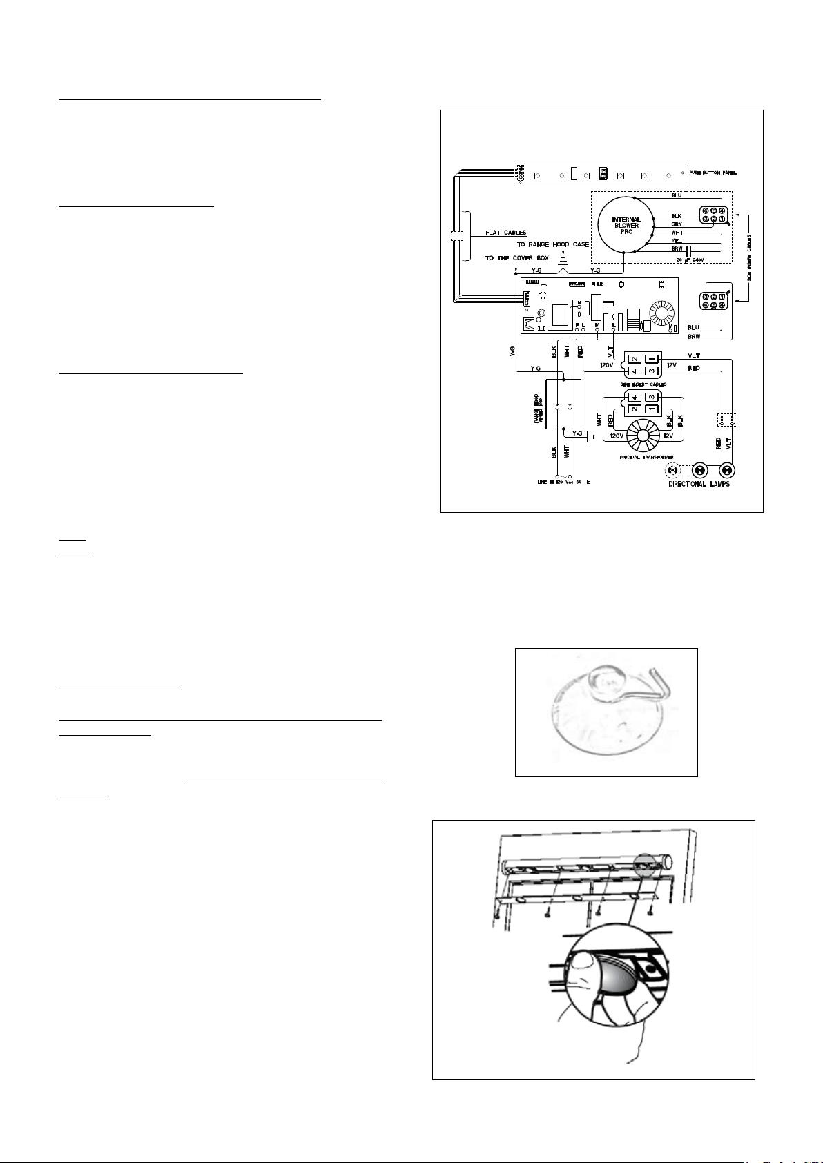
USE AND CARE CONTINUED - MAINTENANCE
Replacing the Lamps
Purchase halogen bulb - (Max 20W, 12V, type MR11 bulb
with glass lens)
USE CAUTION AS THE BULB MAY
BE HOT(as indicated in FIGURE
14)
FIGURE 15
FIGURE 14
WIRING DIAGRAM
FIGURE 15
Grease Filter and Charcoal Filter Alarm Reset
Charcoal Filter Information
(as indicated in FIGURE
7 on page 8)
Charcoal Filter Alarm Activation
"B" button
"B" button
"B" button
"EF"
"EF"
I Schema Elettrico NL Schema Electrisch
GB Electric Diagram E Esquema Eléctrico
F Schéma Electrique Esquema Eléctrico
D Schema Elektrisch
I Schema Elettrico NL Schema Electrisch
GB Electric Diagram E Esquema Eléctrico
F Schéma Electrique Esquema Eléctrico
D Schema Elektrisch
PT
PT
436003384 SF5_023 r- 436003384 SF5_023 r-

Version 09/12 - Page 10
FABER WARRANTY & SERVICE (SAVE FOR YOUR RECORDS)
The Following is not covered by Faber's warranty:
Record Your Information Below:
Serial #: __________________________
Date of Purchase: ______________
Version 09/12 - Page 11
Pour de meilleurs résultats, ne pas utiliser plus de trois coudes de
90
o
. S’assurer qu’il y ait un minimum de 24 po de conduit droit entre
les coudes si l’on utilise plus d’un coude. Ne pas installer deux
coudes ensemble.
FIGURE 3FIGURE 2
PLAN DE L’INSTALLATION
AVERTISSEMENT!
FIGURE 1
A. HOTTE
B. CROCHETS DE MONTAGE AVEC VIS
C. GRILLE POUR INSTALLATION SANS CONDUIT
D. CONDUITE DE TRANSITION ARRIÈRE DE LA
CHEMINÉE
E. CHEMINÉE / VIS POUR CONDUIT
F. VIS DE SÉCURITÉ
G. COUVERCLE DE LA GRILLE
H. VIS POUR COUVERCLE DE LA GRILLE
I. LE REGISTRE
A
B
C
D
E
F
G
M
I
OUTILS NÉCESSAIRES À L’INSTALLATION
PIÈCES FOURNIES POUR L’INSTALLATION
PIÈCES NÉCESSAIRES POUR L’INSTALLATION
ACCESSOIRES POUR L’INSTALLATION
REMPLACEMENT DU FILTRE AU CHARBON
Pour installation sans conduit seulement.
Remplacer le filtre au charbon lorsque
nécessaire (pièce # FILTER1)
• COUVERCLE DE LA CHEMINÉE (OPTIONNEL)
Pour installation où la ventilation arrière/
recirculation est impossible ou non désirée.
Lors de ventilation au-dessus, vous pouvez
acheter un couvercle de cheminée en acier
inoxydable pour couvrir le conduit, pièce #
(cheminée basse) et pièce #
(cheminée du dessus).
ASSEMBLAGE DE LA HOTTE
CALCUL DE LONGUEUR DU CONDUIT
FIGURE 2
FIGURE 3
AVERTISSEMENT
!
Version 09/12 - Page 12
DIMENSIONS D’INSTALLATION AVEC CONDUIT
11”
DIMENSIONS D’INSTALLATION SANS CONDUIT
PRÉPARATION DU MUR
1.
2.
3.
FIGURE 5
5.
B
F
G
FIGURE 4
NSTALLATION DE LA HOTTE
1.
6.
FIGURE 6
POUR TOUT LES INSTALLATIONS
1.
Schéma 7
Avertissement: Les Vis Fournies Pour Le Montage De Cette
Hotte De Cuisinière Doivent Être Insérées Dans Du Bois
Solide. Elle Ne Doivent Pas Être Insérées Dans Un Mur Ou
Un Plafond De Plâtre.
15"
19 7/16"
43"
FIGURE 7
7 7/8"
9
INSTALLATIONS AVEC CONDUIT
FIGURE 8
1.
FIGURE 9
C
E
H
I
INSTALLATION SANS CONDUIT
1.
POUR TOUTES LES INSTALLATIONS
1.
-
FIGURE 10
UTILISATION ET ENTRETIEN
Pour de meilleurs résultats
Contrôle À Distance
FIGURE 11
Nettoyage
FIGURE 12
PANNEAU DE CONTRÔLE - UTILISATION ET ENTRETIEN (SUITE)
le mode délai de fermeture de 30 minutes
la fonction - 24 heures
Bouton
A
D
E
F
Fonction
fonction de charge intensive
la fonction - 24 heures
rafraîchir
ou nettoyer
le mode délai de fermeture de 30
minutes
Afchage des Symboles LED
HI
la fonction - 24 heures
FF
Voir sur la page suivante les
instructions pour réactiver l'alarme.
EF
Voir sur la page suivante les instructions pour
réactiver l'alarme.
FIGURE 13
A
B
C
D
E
F
G
H
LED
T1 T2 T3 T4 T5 T6 T7
IT
Accende e
spegne
líimpianto
di illumina-
zione.
Accende e
spegne
líimpianto di
illuminazione
ad intensit‡
ridotta.
Accende e spe-
gne il motore di
aspirazione
allíultima velocit‡
utilizzata.
Decrementa
la velocit‡ di
esercizio.
Incrementa
la velocit‡ di
esercizio.
Attiva la velocit‡ intensiva da qualsiasi velocit‡ anche da
motore spento, tale velocit‡ Ë temporizzata a 10 minuti, al
termine del tempo il sistema ritorna alla velocit‡ precedente-
mente impostata. Adatta a fronteggiare le massime emissioni
di fumi di cottura.
- Attiva lo spegnimento automatico ritardato di 30í. Adatto per completare
líeliminazione di odori residui. Attivabile da qualsiasi posizione, si disattiva
premendo il tasto o spegnendo il motore.
- Premendo per circa 2î il tasto,attiva il motore ad una velocit‡ che consente
uníaspirazione di 100 m3/h per 10 minuti ogni ora, terminati il motore si
ferma.
GB
Turns light
on and off .
Turns light on
and off at
reduced
intensity.
Switches the
extractor motor on
and off at the
latest selected
speed
Decreases
the suction
speed.
Increases
the suction
speed.
By pressing this key it is possible to activate the intensive
speed from any previously selected speed. The intensive
speed can be activated even when the motor is OFF. This
speed has been timed at 10 minutes. After that time the sys-
tem activates automatically the latest selected speed. This
function is suitable for cooking conditions when vapours and
smells are of the utmost emission.
- By pressing this key it is possible to set the delayed shutdown of the ap-
pliance to 30 minutes. This function is suitable for a complete elimination of
the residual smells. It can be activated at any position, and it is deactivated
by pressing the key again or by switching off the motor.
- Press the button for approximately 2", it is possible to set up the motor to a
suction speed at 100 m
3
/h lasting 10 minutes every hour. After this the
motor switches off automatically.
FR
Allume et
Èteint
líÈclairage.
Allume et
Èteint
líÈclairage ‡
intensitÈ
rÈduite.
Allume et Èteint le
moteur
díaspiration ‡ la
derniËre vitesse
utilisÈe
Diminue la
vitesse de
service
Augmente la
vitesse de
service
Active la vitesse intensive ‡ partir de níimporte quelle vitesse,
mÍ me du moteur arrÍ tÈ. Cette vitesse est programmÈe pour
durer 10 minutes, aprËs quoi le systËme retourne ‡ la vitesse
rÈglÈe au prÈalable. Sert ‡ faire face ‡ une quantitÈ maximale
de fumÈes de cuisson.
- Active líarrÍ t automatique retardÈ de 30 minutes. Utile pour achever
díÈliminer toute odeur rÈsiduelle. Síactive depuis toutes les positions et se
dÈsactive en appuyant sur la touche ou en Èteignant le moteur.
- En appuyant pendant 2" environ sur la touche, active le moteur ‡ une
vitesse permettant une aspiration de 100 m
3
/h pendant 10 minutes toutes
les heures, puis le moteur síarrÍ te.
DE
Schaltet die
Beleuchtun
g ein oder
aus.
Schaltet die
verminderte
Beleuchtung
ein oder aus.
Schaltet den
Motor der
Absauganlage bei
der zuletzt
verwendeten
Geschwindigkeit
ein und aus.
Vermindert
die
Betriebsges
chwindigkeit
.
Erhˆht die
Betriebsges
chwindigkeit
.
Aktiviert von jeder Geschwindigkeit aus, auch bei abgestelltem
Motor, die Intensivgeschwindigkeit, die auf 10 Minuten
zeitgeregelt ist. Nach Ablauf dieser Zeit kehrt das System zu
der zuvor eingestellten Geschwindigkeit zur¸ck. F¸ r die
Beseitigung von sehr intensiven Kochd¸nsten geeignet.
- Aktiviert das automatische Ausschalten mit einer Verzˆgerung von 30 Min.
Ermˆglicht die Beseitigung von Restger¸chen und kann von jeder Position
aus aktiviert werden. Zum Deaktivieren die Taste dr¸cken oder den Motor
abstellen.
- Wird durch cirka 2" dauerndes Dr¸ cken der Taste aktiviert den Motor bei
einer Geschwindigkeit, die eine Absaugleistung von 100 m3/h f¸r die
Dauer von 10 Minuten jede Stunde ermˆglicht, nach dessen Ablauf h‰lt der
Motor an.
TR
!YDNLATMA
sistemini
aÁar-
KAPATR
!YDNLATMA
sistemini
d¸àKKTA
A¥ARKAPATR
Aspiratˆ r
motorunu,
KULLANLANENSON
HZDAA¥P
KAPATR
O an
devrede
OLANHZ
d¸¸ r¸ r.
O an
devrede
OLANHZ
ARTTRR
-OTORKAPALYKENBILEHERHANGIBIRHZDANYOUNHZDEVREYE
ALRBUHZDAKIKAYAAYARLDRVEBUSàRENINSONUNDASISTEM
DAHAÚNCEAYARLANMOLANHZADÚNER%NYàKEKYOunluktaki
piIRMEDUMANLARNNTAHLIYESINEUYGUNDUR
DAKIKASONRAOTOMATIKKAPATMAPROGRAMNDEVREYEALR0IIRMESONRAS
KALANARTKKOKULARYOKETMEKI¥INUYGUNDUR(ANGIKONUMDAOLUNURSAO
LUNSUNDEVREYEALNABILIRVETUa basmak yada motoru stop etmek suretiyle
DEVREDBRAKLABILIR
- iken tua 3 saniye, motoru her saat baDAKIKASàREILEMÃSAAT
ORANNDAHAVAEMECEKEKILDE¥ALTRRBUSàREDOLUNCAMOTORSTOPEDER
436003288_01 -- 060511
FIGURE 14
G
H
A
B
C
D
E / F

ENTRETIEN - UTILISATION ET ENTRETIEN (SUITE)
Replacer Les Lampes
(de la FIGURE 15)
FIGURE 14
DIAGRAMME DE CÂBLAGE
FIGURE 15
Réactivation de l'Alarme des Filtres à Graisse et au
Charbon
Information sur le ltre au charbon
(tel qu'indiqué sur
la FIGURE 7 de la page 8)
Activation de l'Alarme du Filtre au Charbon
le
bouton "B"
le bouton "B"
"EF"
"EF"
I Schema Elettrico NL Schema Electrisch
GB Electric Diagram E Esquema Eléctrico
F Schéma Electrique Esquema Eléctrico
D Schema Elektrisch
I Schema Elettrico NL Schema Electrisch
GB Electric Diagram E Esquema Eléctrico
F Schéma Electrique Esquema Eléctrico
D Schema Elektrisch
PT
PT
436003384 SF5_023 r- 436003384 SF5_023 r-
Achat ampoule halogène - (Max 20W, 12V, type MR11
ampoule avec lentille en verre)
FAIRE ATTENTION QUE
L'AMPOULE PEUT ÊTRE CHAUD

FABER GARANTIE ET SERVICE (
ÉCONOMISER POUR VOS ENREGISTREMENTS
)
Les frais suivants ne sont pas couverts par la garantie Faber :
Enregistrez Votre Information Ci-dessous:
Séquentiel #: __________________________
Date d'achat: ______________