Issue 07/2022 Art. No. 7001-0326
Operating Manual
CB / CB-UL, CBF / CBF-UL (E7)
CO
2
Incubators
CO
2
Incubators with O
2
Control
CO
2
Incubators with Humidity control
with sterilizable NDIR sensor system for CO
2
and microprocessor display program controller MB2 with touchscreen
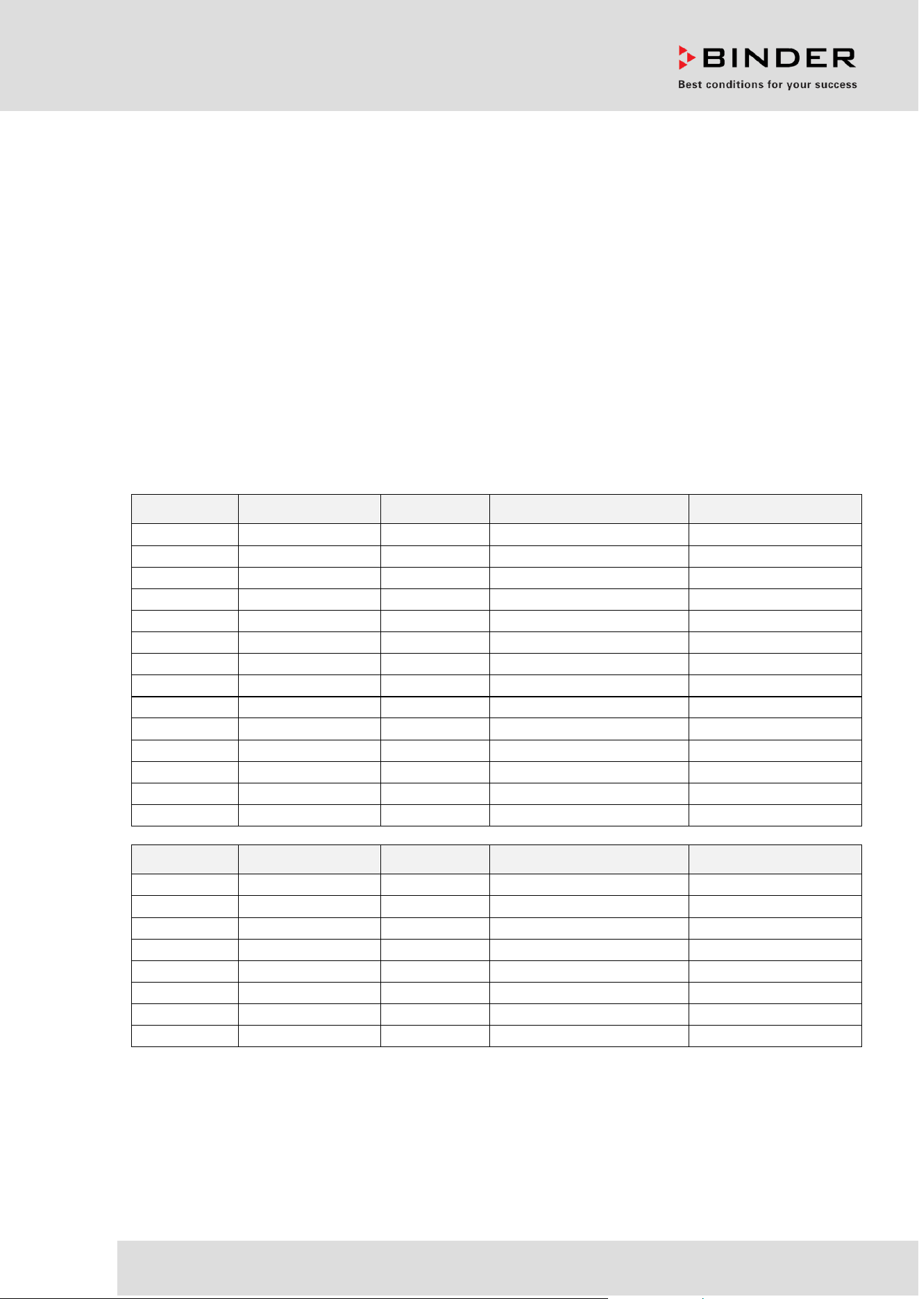
Model Model version Voltage Equipment Art. no.
CB 56
CB56-230V
200-230 V
9640-0005
CB 56
CB56-230V-O
200-230 V
O
2
control 0-20 vol.-%
9640-0006
CB 56-UL
CB56-120V
100-120 V
9640-0007
CB 56-UL
CB56-120V-O
100-120 V
O
2
control 0-20 vol.-%
9640-0008
CB 170
CB170-230V
200-230 V
9640-0009
CB 170
CB170-230V-D
200-230 V
Access port 30 mm, left
9640-0027
CB 170
CB170-230V-O
200-230 V
O
2
control 0-20 vol.-%
9640-0010
CB 170-UL
CB170-120V
100-120 V
9640-0011
CB 170-UL
CB170UL-120V-D
100-120 V
Access port 30 mm, left
9640-0028
CB 170-UL
CB170-120V-O
100-120 V
O
2
control 0-20 vol.-%
9640-0012
CB 260
CB260-230V
200-230 V
9640-0013
CB 260
CB260-230V-O
200-230 V
O
2
control 0-20 vol.-%
9640-0014
CB 260-UL
CB260-120V
100-120 V
9640-0015
CB 260-UL
CB260-120V-O
100-120 V
O
2
control 0-20 vol.-%
9640-0016
Model Model version Voltage Equipment Art. no.
CBF 170
CBF170-230V
200-230 V
9640-0017
CBF 170
CBF170-230V-O
200-230 V
O
2
control 0-20 vol.-%
9640-0018
CBF 170-UL
CBF170-120V
100-120 V
9640-0019
CBF 170-UL
CBF170-120V-O
100-120 V
O
2
control 0-20 vol.-%
9640-0020
CBF 260
CBF260-230V
200-230 V
9640-0021
CBF 260
CBF260-230V-O
200-230 V
O
2
control 0-20 vol.-%
9640-0022
CBF 260-UL
CBF260-120V
100-120 V
9640-0023
CBF 260-UL
CBF260-120V-O
100-120 V
O
2
control 0-20 vol.-%
9640-0024
BINDER GmbH
Address: Post office box 102, 78502 Tuttlingen, Germany Phone: +49 7462 2005 0
Fax: +49 7462 2005 100 Internet: http://www.binder-world.com
E-mail: info@binder-world.com Service Hotline: +49 7462 2005 555
Service Fax: +49 7462 2005 93 555 Service E-Mail: customerservice@binder-world.com
Service Hotline USA: +1 866 885 9794 or +1 631 224 4340 x3
Service Hotline Asia Pacific: +852 390 705 04 or +852 390 705 03
Service Hotline Russia and CIS: +7 495 988 15 16

CB / CB-UL, CBF / CBF-UL (E7) 07/2022 Page 2/199
Contents
1. SAFETY .................................................................................................................. 8
1.1 Personnel Qualification ....................................................................................................................... 8
1.2 Operating manual ................................................................................................................................ 8
1.3 Legal considerations ........................................................................................................................... 8
1.3.1 Intellectual property ................................................................................................................... 9
1.4 Structure of the safety instructions ...................................................................................................... 9
1.4.1 Signal word panel ..................................................................................................................... 9
1.4.2 Safety alert symbol ................................................................................................................. 10
1.4.3 Pictograms .............................................................................................................................. 10
1.4.4 Word message panel structure ............................................................................................... 11
1.5 Localization / position of safety labels on the chamber .................................................................... 11
1.6 Type plate.......................................................................................................................................... 12
1.7 UKCA Label ...................................................................................................................................... 13
1.8 General safety instructions on installing and operating the CO
2
incubator....................................... 14
1.9 Precautions when working with gases .............................................................................................. 16
1.10 Precautions when handling gas cylinders ......................................................................................... 17
1.11 Intended use ..................................................................................................................................... 18
1.12 Foreseeable Misuse .......................................................................................................................... 20
1.13 Residual Risks .................................................................................................................................. 20
1.14 Operating instructions ....................................................................................................................... 22
1.15 Measures to prevent accidents ......................................................................................................... 22
1.16 CBF / CBF-UL : Resistance of the humidity sensor against harmful substances ............................. 23
2. CHAMBER DESCRIPTION .................................................................................. 24
2.1 Chamber overview ............................................................................................................................ 25
2.2 Inner chamber ................................................................................................................................... 26
2.3 Control panel on the rear of the chamber ......................................................................................... 27
2.4 Instrument panel ............................................................................................................................... 28
3. COMPLETENESS OF DELIVERY, TRANSPORTATION, STORAGE, AND
INSTALLATION .................................................................................................... 28
3.1 Unpacking, and checking equipment and completeness of delivery ................................................ 28
3.2 Guidelines for safe lifting and transportation ..................................................................................... 29
3.3 Storage .............................................................................................................................................. 29
3.4 Location of installation and ambient conditions ................................................................................ 30
4. INSTALLATION AND CONNECTIONS ............................................................... 33
4.1 Shelves .............................................................................................................................................. 33
4.2 Permadry™ water pan ...................................................................................................................... 34
4.3 Connecting the O
2
sensor (chamber with O
2
control) ....................................................................... 35
4.4 Gas connections ............................................................................................................................... 35
4.4.1 Connection of the CO
2
gas cylinder ........................................................................................ 36
4.4.2 Connection of the O
2
gas cylinder (chamber with O
2
control with optional alternative control
range 10 up to 95 vol.-% O
2
) .................................................................................................. 37
4.4.3 Connection of the N
2
gas cylinder (chamber with O
2
control)................................................. 38
4.4.4 Connecting the gas hose to the chamber rear (for CO
2
, O
2
, N
2
) ............................................ 39
4.4.5 Gas cylinder connection kits (option) ...................................................................................... 41
4.5 CBF / CBF-UL: Water supply and dehumidification .......................................................................... 41
4.5.1 General remarks on water supply ........................................................................................... 41
4.5.1.1 Water supply .................................................................................................................... 41
4.5.1.2 Dehumidification .............................................................................................................. 42
4.5.1.3 Types of suitable water quality ........................................................................................ 42
4.5.1.4 BINDER Pure Aqua Service (option) ............................................................................... 42

CB / CB-UL, CBF / CBF-UL (E7) 07/2022 Page 3/199
4.5.2
Water supply via freshwater bag (standard) ........................................................................... 43
4.5.2.1 Scope of delivery ............................................................................................................. 43
4.5.2.2 Installation and connection of the freshwater bag ........................................................... 43
4.5.2.3 Refilling the already installed freshwater bag .................................................................. 44
4.5.2.4 Replacing the tube connectors for freshwater supply ..................................................... 45
4.5.3 Water supply via prefilled water bottle (optional humidification water set) ............................. 46
4.5.3.1 Scope of delivery ............................................................................................................. 46
4.5.3.2 Installation, connection and change of the prefilled water bottle .................................... 46
4.5.4 Water supply via freshwater can (optional water container set) ............................................. 48
4.5.4.1 Scope of delivery ............................................................................................................. 49
4.5.4.2 Installation and connection of the freshwater can (optional water container set) ........... 49
4.5.4.3 Refilling the freshwater can ............................................................................................. 51
4.6 Electrical connection ......................................................................................................................... 52
4.7 Divided inner door with cell therapy compartmentation (optional) .................................................... 53
4.7.1 Special model CBF 260 “Cell Therapy” .................................................................................. 53
4.7.2 Handling and aligning the divided inner door ......................................................................... 54
4.7.3 Mounting the partition walls for cell therapy compartmentation ............................................. 55
5. FUNCTIONAL OVERVIEW OF THE MB2 CHAMBER CONTROLLER ............... 57
5.1 Operating functions in normal display ............................................................................................... 58
5.2 Display views: Normal display, program display, chart-recorder display .......................................... 59
5.3 Controller icons overview .................................................................................................................. 60
5.4 Operating modes ............................................................................................................................... 62
5.5 Controller menu structure .................................................................................................................. 62
5.5.1 Main menu .............................................................................................................................. 63
5.5.2 “Settings” submenu ................................................................................................................. 64
5.5.3 “Service” submenu .................................................................................................................. 64
5.6 Principle of controller entries ............................................................................................................. 65
5.7 Performance during and after power failures .................................................................................... 65
5.8 Performance when opening the door ................................................................................................ 66
6. START UP ............................................................................................................ 66
6.1 Turning on the chamber .................................................................................................................... 66
6.2 Controller settings upon start up ....................................................................................................... 67
6.3 Factory settings ................................................................................................................................. 68
6.4 Equilibration time ............................................................................................................................... 68
6.5 Operating the DuoDoor™ door lock .................................................................................................. 69
6.6 Required gas supply for the chamber with O
2
control ....................................................................... 69
6.6.1 Hypoxic control range 0.2 vol.-% up to 20 vol.- % O
2
(regular) .............................................. 69
6.6.2 Alternative control range 10 vol.-% up to 95 vol.-% (option) .................................................. 69
6.6.3 Operation without O
2
control ................................................................................................... 70
6.7 Activating / deactivating CO
2
, O
2
and humidity control ..................................................................... 70
6.8 CB / CB-UL: Humidity control of the Permadry™ system ................................................................. 71
7. SET-POINT ENTRY IN “FIXED VALUE” OPERATING MODE ........................... 72
7.1 Set-point entry through the “Setpoints” menu ................................................................................... 73
7.2 Direct setpoint entry via Normal display ............................................................................................ 74
7.3 Special controller functions via operation lines ................................................................................. 75
7.4 Safety instructions for setting high gas concentrations ..................................................................... 76
8. TIMER PROGRAM: STOPWATCH FUNCTION .................................................. 77
8.1 Starting a timer program ................................................................................................................... 77
8.1.1 Performance during program delay time ................................................................................ 77
8.2 Stopping a running timer program .................................................................................................... 78
8.2.1 Pausing a running timer program ........................................................................................... 78
8.2.2 Cancelling a running timer program ........................................................................................ 78
8.3 Performance after the end of the program ........................................................................................ 78

CB / CB-UL, CBF / CBF-UL (E7) 07/2022 Page 4/199
9. TIME PROGRAMS ............................................................................................... 79
9.1 Starting an existing time program ..................................................................................................... 79
9.1.1 Performance during program delay time ................................................................................ 80
9.2 Stopping a running time program ...................................................................................................... 80
9.2.1 Pausing a running time program ............................................................................................. 80
9.2.2 Cancelling a running time program ......................................................................................... 80
9.3 Performance after the end of the program ........................................................................................ 80
9.4 Creating a new time program ............................................................................................................ 81
9.5 Program editor: program management ............................................................................................. 81
9.5.1 Deleting a time program.......................................................................................................... 82
9.6 Section editor: section management ................................................................................................. 83
9.6.1 Add a new program section .................................................................................................... 84
9.6.2 Copy and insert or replace a program section ........................................................................ 84
9.6.3 Deleting a program section ..................................................................................................... 85
9.7 Value entry for a program section ..................................................................................................... 86
9.7.1 Section duration ...................................................................................................................... 86
9.7.2 Set-point ramp and set-point step ........................................................................................... 87
9.7.3 Special controller functions via operation lines ....................................................................... 89
9.7.4 Setpoint entry .......................................................................................................................... 90
9.7.5 Tolerance range ...................................................................................................................... 90
9.7.6 Repeating one or several sections within a time program ...................................................... 91
9.7.7 Saving the time program ......................................................................................................... 92
10. WEEK PROGRAMS ............................................................................................. 92
10.1 Starting an existing week program .................................................................................................... 92
10.2 Cancelling a running week program ................................................................................................. 93
10.3 Creating a new week program .......................................................................................................... 93
10.4 Program editor: program management ............................................................................................. 94
10.4.1 Deleting a week program ........................................................................................................ 95
10.5 Section editor: section management ................................................................................................. 96
10.5.1 Add a new program section .................................................................................................... 97
10.5.2 Copy and insert or replace a program section ........................................................................ 97
10.5.3 Deleting a program section ..................................................................................................... 98
10.6 Value entry for a program section ..................................................................................................... 98
10.6.1 Set-point ramp and set-point step modes ............................................................................... 98
10.6.2 Weekday ................................................................................................................................. 99
10.6.3 Start time ................................................................................................................................. 99
10.6.4 Setpoint entry ........................................................................................................................ 100
10.6.5 Special controller functions via operation lines ..................................................................... 100
11. NOTIFICATION AND ALARM FUNCTIONS ...................................................... 101
11.1 Notification and alarm messages overview ..................................................................................... 101
11.1.1 Notifications .......................................................................................................................... 101
11.1.2 Alarm messages ................................................................................................................... 102
11.2 State of alarm .................................................................................................................................. 104
11.3 Resetting an alarm, list of active alarms ......................................................................................... 104
11.4 Activating / deactivating the audible alarm (alarm buzzer) ............................................................. 105
11.5 Tolerance range settings and alarm delay times ............................................................................ 105
11.6 Zero-voltage relay alarm output ...................................................................................................... 107
12. TEMPERATURE SAFETY DEVICES ................................................................. 108
12.1 Over temperature protective device (class 1) ................................................................................. 108
12.2 Overtemperature safety controller class 3.1 ................................................................................... 108
12.2.1 Safety controller modes ........................................................................................................ 109
12.2.2 Setting the safety controller .................................................................................................. 109
12.2.3 Message and measures in the state of alarm ....................................................................... 110
12.2.4 Function check ...................................................................................................................... 110

CB / CB-UL, CBF / CBF-UL (E7) 07/2022 Page 5/199
13. USER MANAGEMENT ....................................................................................... 111
13.1 Authorization levels and password protection................................................................................. 111
13.2 Log in ............................................................................................................................................... 114
13.3 Log out ............................................................................................................................................ 115
13.4 User change .................................................................................................................................... 115
13.5 Password assignment and password change................................................................................. 116
13.5.1 Password change ................................................................................................................. 116
13.5.2 Deleting the password for an individual authorization level .................................................. 118
13.5.3 New password assignment for “service” or “admin” authorization level when the password
function was deactivated ...................................................................................................... 119
13.6 Activation code ................................................................................................................................ 120
14. GENERAL CONTROLLER SETTINGS .............................................................. 121
14.1 Selecting the controller’s menu language ....................................................................................... 121
14.2 Setting date and time ...................................................................................................................... 121
14.3 Selecting the temperature unit ........................................................................................................ 123
14.4 Display configuration ....................................................................................................................... 123
14.4.1 Adapting the display parameters .......................................................................................... 123
14.4.2 Touchscreen calibration ........................................................................................................ 124
14.5 Network and communication ........................................................................................................... 125
14.5.1 Serial RS485 interface (available via BINDER INDIVIDUAL Customized Solutions) .......... 125
14.5.2 Ethernet ................................................................................................................................ 126
14.5.2.1 Configuration ................................................................................................................. 126
14.5.2.2 Display of MAC address ................................................................................................ 127
14.5.3 Web server ............................................................................................................................ 127
14.5.4 E-Mail .................................................................................................................................... 128
14.6 USB menu: Data transfer via USB interface ................................................................................... 129
15. GENERAL INFORMATION ................................................................................ 130
15.1 Service contact page ....................................................................................................................... 130
15.2 Current operating parameters ......................................................................................................... 130
15.3 Event list .......................................................................................................................................... 131
15.4 Technical chamber information ....................................................................................................... 131
16. CHART RECORDER DISPLAY ......................................................................... 132
16.1 Views ............................................................................................................................................... 132
16.1.1 Show and hide legend .......................................................................................................... 132
16.1.2 Switch between legend pages .............................................................................................. 132
16.1.3 Show and hide specific indications ....................................................................................... 133
16.1.4 History display ....................................................................................................................... 133
16.2 Setting the parameters .................................................................................................................... 136
17. CBF / CBF-UL: HUMIDIFICATION SYSTEM ..................................................... 137
17.1 Function of the humidifying system ................................................................................................. 137
17.2 Function of the dehumidifying system ............................................................................................. 138
18. OPTIONS ............................................................................................................ 138
18.1 APT-COM™ 4 Multi Management Software (option) ...................................................................... 138
18.2 Silicone access ports 30 mm / 1.18 in, closable from both sides with silicon plugs (option) .......... 138
18.3 Quick sample access (option) ......................................................................................................... 139
18.4 Interior socket 230V (option, available via BINDER INDIVIDUAL Customized Solutions) ............. 140
18.5 Analog outputs for temperature and CO
2
(option) .......................................................................... 141
18.6 Access port for extra-low voltage (option) ....................................................................................... 142
18.7 BINDER Gas Supply Service – External bottle changer for CO
2
, N
2
or O
2
(option) ....................... 143
18.8 Stands ............................................................................................................................................. 143
18.8.1 Flat stacking adapter for thermally decoupled stacking (option) .......................................... 143
18.8.2 Stacking stand on castors with castors lockable by breaks (option) .................................... 143
18.8.3 Base on castors (option) ....................................................................................................... 144

CB / CB-UL, CBF / CBF-UL (E7) 07/2022 Page 6/199
18.9
Water supply sets (optional for CBF / CBF-UL) .............................................................................. 144
18.9.1 Tubular bag set (option) ........................................................................................................ 144
18.9.2 Humidification water set (option) .......................................................................................... 144
18.9.3 Water container set (option) ................................................................................................. 144
19. REFERENCE MEASUREMENTS ...................................................................... 144
19.1 CO
2
reference measuring ............................................................................................................... 145
19.1.1 Measuring CO
2
concentration indirectly via the pH of the cell medium ................................ 145
19.1.2 Measuring CO
2
directly via chemical indicator tubes............................................................ 146
19.1.3 Measuring CO
2
directly with an electronic infrared measuring device ................................. 146
19.2 Temperature reference measurement ............................................................................................ 146
20. AVOIDING MICROBIAL CONTAMINATION...................................................... 146
20.1 Cells and media .............................................................................................................................. 146
20.2 Laboratory conditions / equipment around the incubator ................................................................ 147
20.3 Working and behavior in the lab ..................................................................................................... 147
20.4 Chamber design and equipment of the CO
2
incubator ................................................................... 147
20.5 Handling the CO
2
incubator ............................................................................................................ 148
21. CLEANING, DECONTAMINATION / DISINFECTION, AND STERILIZATION .. 149
21.1 Cleaning .......................................................................................................................................... 150
21.2 Decontamination / chemical disinfection of the chamber ................................................................ 151
21.2.1 Disinfection of the CO
2
sensor .............................................................................................. 153
21.2.2 CBF / CBF-UL: Disinfection of components of the fresh water supply system .................... 153
21.3 Hot-air sterilization .......................................................................................................................... 153
21.3.1 Overview ............................................................................................................................... 153
21.3.2 Preparation for a hot-air sterilization ..................................................................................... 154
21.3.3 Starting the sterilization cycle and running the hot-air sterilization ....................................... 155
21.3.4 Prematurely terminating the sterilization cycle ..................................................................... 157
21.3.4.1 Prematurely terminating the sterilization cycle after less than 4 hours: Ineffective
sterilization .................................................................................................................... 157
21.3.4.2 Prematurely terminating the sterilization cycle after more than 4 hours, i.e., during the
cooling-down phase: successful sterilization ................................................................ 158
21.3.5 Completing the entire sterilization cycle ............................................................................... 159
22. MAINTENANCE AND SERVICE, TROUBLESHOOTING, REPAIR, TESTING . 159
22.1 General information, personnel qualification................................................................................... 159
22.2 CBF / CBF-UL: Replacing components of the humidifying / dehumidifying system ....................... 160
22.2.1 Replacing the silicone tube of the fresh water supply system .............................................. 160
22.2.2 Replacing the pump head of the fresh water supply system ................................................ 160
22.2.3 Replacing the gas fine filter (sterile filter) for ambient air ..................................................... 160
22.3 Replacing the CO
2
und O
2
/N
2
gas inlet fine filters (sterile filters) .................................................... 161
22.4 Replacing the CO
2
sensor ............................................................................................................... 162
22.5 Maintenance intervals, service ........................................................................................................ 163
22.6 Simple troubleshooting .................................................................................................................... 164
22.6.1 General ................................................................................................................................. 164
22.6.2 Heating .................................................................................................................................. 165
22.6.3 Gas cylinder pressure too low .............................................................................................. 166
22.6.4 Gas control ............................................................................................................................ 167
22.6.5 Sterilization ........................................................................................................................... 169
22.6.6 Humidity (CB / CB-UL) .......................................................................................................... 169
22.6.7 Humidity (CBF / CBF-UL) ..................................................................................................... 170
22.6.8 Controller .............................................................................................................................. 170
22.6.9 Open door ............................................................................................................................. 171
22.7 Sending the chamber back to BINDER GmbH ............................................................................... 171

CB / CB-UL, CBF / CBF-UL (E7) 07/2022 Page 7/199
23. DISPOSAL.......................................................................................................... 172
23.1 Disposal of the transport packing .................................................................................................... 172
23.1.1 Outer chamber packing......................................................................................................... 172
23.1.2 Packing inside the chamber and equipment ......................................................................... 172
23.2 Decommissioning ............................................................................................................................ 173
23.3 Disposal of the chamber in the Federal Republic of Germany ....................................................... 173
23.4 Disposal of the chamber in the member states of the EU except for the Federal Republic of
Germany.......................................................................................................................................... 174
23.5 Disposal of the chamber in non-member states of the EU ............................................................. 176
24. TECHNICAL DESCRIPTION .............................................................................. 176
24.1 Factory calibration and adjustment ................................................................................................. 176
24.2 Over current protection ................................................................................................................... 176
24.3 Definition of usable volume ............................................................................................................. 177
24.4 Technical data ................................................................................................................................. 177
24.5 Equipment and Options (extract) .................................................................................................... 180
24.6 Accessories and spare parts (extract) ............................................................................................ 181
24.7 Important conversion data for non-SI units ..................................................................................... 184
24.8 Conversion table for gas inlet pressures, bar – psi ......................................................................... 184
24.9 Dimensions...................................................................................................................................... 185
24.9.1 Chamber size 56 ................................................................................................................... 185
24.9.2 Chamber size 170 ................................................................................................................. 186
24.9.3 Chamber size 260 ................................................................................................................. 187
25. CERTIFICATES AND DECLARATIONS OF CONFORMITY ............................. 188
25.1 EU Declaration of conformity for CB ............................................................................................... 188
25.2 EU Declaration of conformity for CBF ............................................................................................. 190
25.3 UKCA Declaration of Conformity for CB ......................................................................................... 192
25.4 UKCA Declaration of Conformity for CBF ....................................................................................... 193
26. CONTAMINATION CLEARANCE CERTIFICATE ............................................. 194
26.1 For chambers located outside the USA and Canada ..................................................................... 194
26.2 For chambers in the USA and Canada ........................................................................................... 197
CB / CB-UL, CBF / CBF-UL (E7) 07/2022 Page 8/199
Dear customer,
For the correct operation of the CO
2
incubator, it is important that you read this operating manual completely
and carefully and observe all instructions as indicated. Failure to read, understand and follow the
instructions may result in personal injury. It can also lead to damage to the chamber and/or poor equipment
performance
1. Safety
1.1 Personnel Qualification
The chamber must only be installed, tested, and started up by personnel qualified for assembly, startup,
and operation of the chamber. Qualified personnel are persons whose professional education, knowledge,
experience and knowledge of relevant standards allow them to assess, carry out, and identify any potential
hazards in the work assigned to them. They must have been trained and instructed, and be authorized, to
work on the chamber.
The chamber should only be operated by laboratory personnel especially trained for this purpose and
familiar with all precautionary measures required for working in a laboratory. Observe the national
regulations on minimum age of laboratory personnel.
1.2 Operating manual
This operating manual is part of the components of delivery. Always keep it handy for reference in the
vicinity of the chamber. If selling the unit, hand over the operating manual to the purchaser.
To avoid injuries and damage observe the safety instructions of the operating manual. Failure to follow
instructions and safety precautions can lead to significant risks.
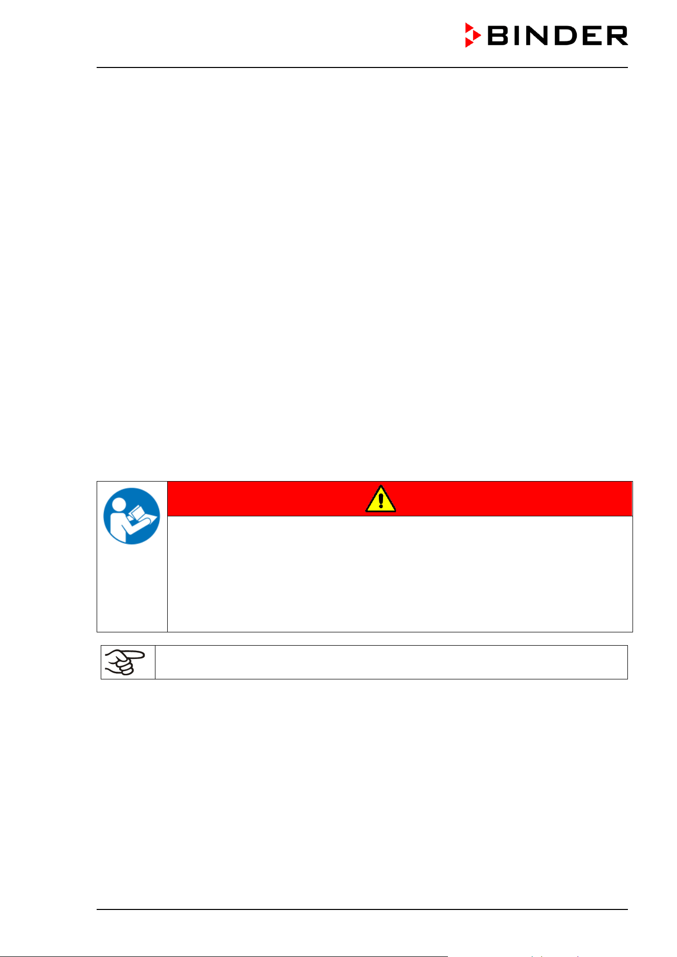
DANGER
Dangers due to failure to observe the instructions and safety precautions.
Serious injuries and chamber damage. Risk of death.
Observe the safety instructions in this Operating Manual.
Follow the operating procedures in this Operating Manual.
Carefully read the complete operating instructions of the chamber
prior to installing and
using the chamber.
Keep the operating manual for future reference
Make sure that all persons who use the chamber and its associated work equipment have
read and understood the Operating Manual.
This Operating Manual is supplemented and updated as needed. Always use the most recent version of
the Operating Manual. When in doubt, call the BINDER Service Hotline for information on the up-to-
dateness and validity of this Operating Manual.
1.3 Legal considerations
This operating manual is for informational purposes only. It contains information for correct and safe
installing, start-up, operation, decommissioning, cleaning and maintenance of the product. Note: the
contents and the product described are subject to change without notice.
Understanding and observing the instructions in this operating manual are prerequisites for hazard-free use
and safety during operation and maintenance. Images are to provide basic understanding. They may
deviate from the actual version of the chamber. The actual scope of delivery can, due to optional or special
design, or due to recent technical changes, deviate from the information and illustrations in these
instructions this operating manual.
CB / CB-UL, CBF / CBF-UL (E7) 07/2022 Page 9/199
In no event shall BINDER be held liable for any damages, direct or incidental arising out of or related to the
use of this manual.
This operating manual cannot cover all conceivable applications. If you would like additional information,
or if special problems arise that are not sufficiently addressed in this manual, please ask your dealer or
contact us directly, e.g. by phone at the number located on page one of this manual
Furthermore, we emphasize that the contents of this operating manual are not part of an earlier or existing
agreement, description, or legal relationship, nor do they modify such a relationship. All obligations on the
part of BINDER derive from the respective purchase contract, which also contains the entire and exclusively
valid statement of warranty administration and the general terms and conditions, as well as the legal
regulations valid at the time the contract is concluded. The statements in this manual neither augment nor
restrict the contractual warranty provisions.
1.3.1 Intellectual property
This operating manual is protected by copyright. Any unauthorized copying or disclosure to third
parties is strictly prohibited. We reserve the right to take legal action and, if necessary, to assert
claims for damages in the event of infringement.
Trademark Information: All BINDER trademarks relating to products or service, as well as trade names,
logos and product names used on the website, products and documents of BINDER company are
trademarks or registered trademarks of BINDER company (including BINDER GmbH, BINDER Inc.) in the
U.S. and other countries and communities of states. This includes word marks, position marks,
word/figurative marks, design configurations, figurative marks, and design patents.
Patent Information: BINDER products, categories of products, and accessories may be covered by one
or more patents and/or utility models in the U.S. and other countries and communities of states. This
information is provided to satisfy the virtual patent marking provisions of various jurisdictions, in particular
it is intended to serve as notice under 35 U.S.C. § 287(a). Products and services listed on the BINDER
website may be sold individually or as part of a combination product. Additional patent applications may
also be pending in the U.S. and other countries and communities of states.
Please visit www.binder-world.com
for more information.
1.4 Structure of the safety instructions
In this operating manual, the following safety definitions and symbols indicate dangerous situations
following the harmonization of ISO 3864-2 and ANSI Z535.6.
1.4.1 Signal word panel
Depending on the probability of serious consequences, potential dangers are identified with a signal word,
the corresponding safety color, and if appropriate, the safety alert symbol.
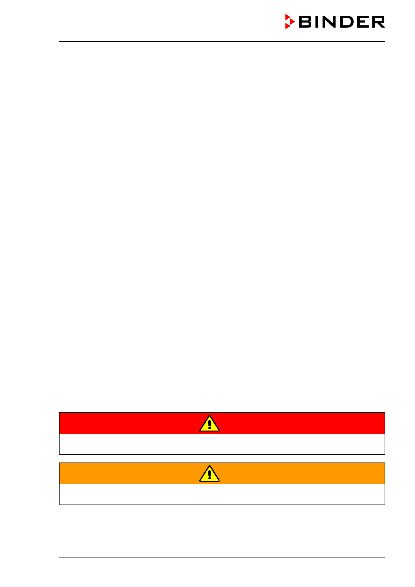
DANGER
Indicates an imminently hazardous situation that, if not avoided, will result in death or serious
(irreversible) injury.
WARNING
Indicates a potentially hazardous situation which, if not avoided, could result in death or serious
(irreversible) injury.
CB / CB-UL, CBF / CBF-UL (E7) 07/2022 Page 10/199
CAUTION
Indicates a potentially hazardous situation which, if not avoided, may result in moderate or minor
(reversible) injury.
NOTICE
Indicates a potentially hazardous situation which, if not avoided, may result in damage to the product
and/or its functions or of a property in its proximity.
1.4.2 Safety alert symbol
Use of the safety alert symbol indicates a risk of injury.
Observe all measures that are marked with the safety alert symbol in order to avoid death or
injury.
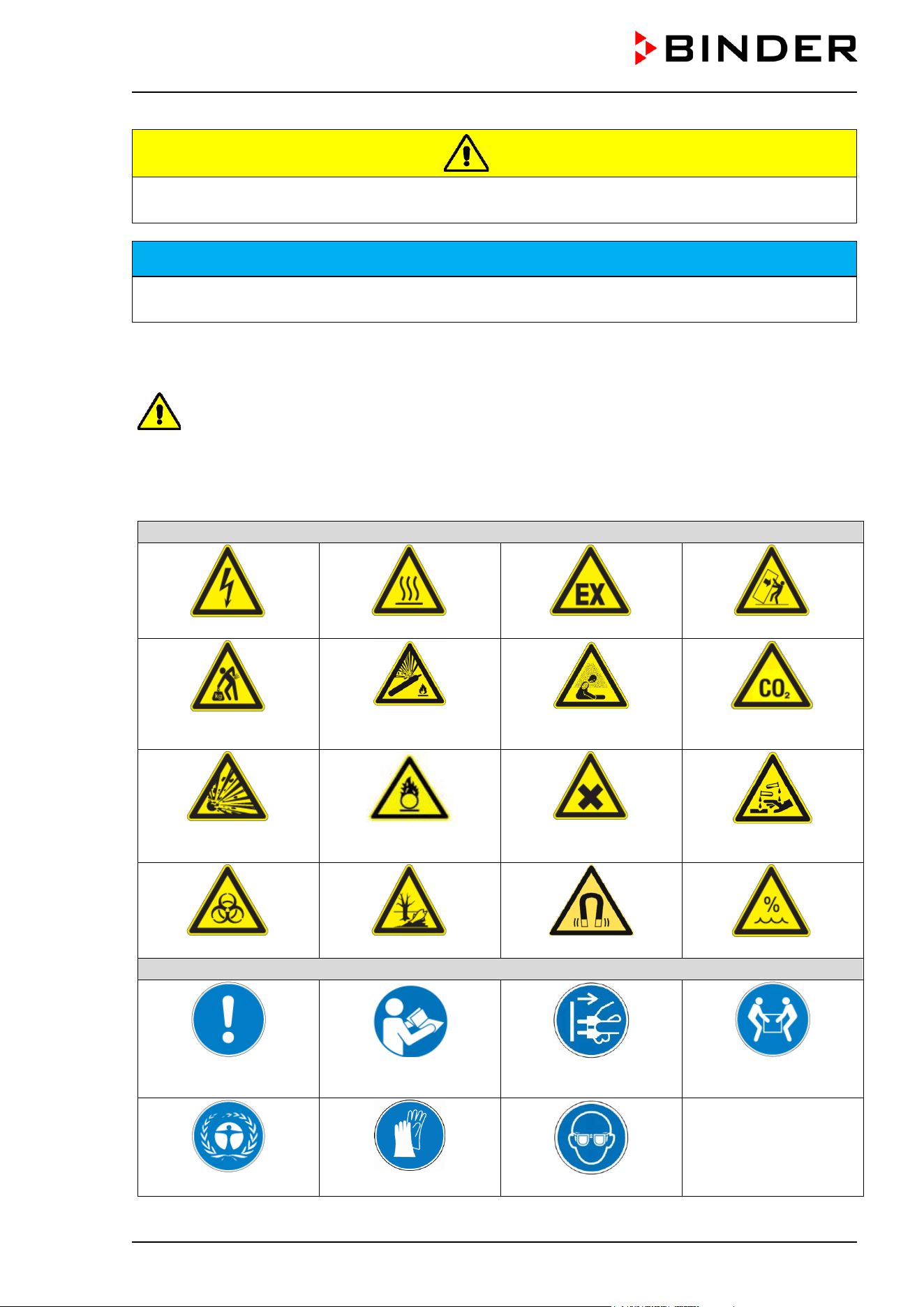
1.4.3 Pictograms
Warning signs
Electrical hazard
Hot surface
Explosive atmosphere
Stability hazard
Lifting hazard
Gas cylinders
Suffocation hazard
CO
2
suffocation and
poisoning hazard
Explosive substances
Fire promoting agents
Harmful substances
Risk of corrosion and /
or chemical burns
Biohazard
Pollution Hazard
Magnetic field
High humidity
Mandatory action signs
Mandatory regulation
Read operating
instructions
Disconnect the power
plug
Lift with several persons
Environment protection
Wear protective gloves
Wear safety goggles
CB / CB-UL, CBF / CBF-UL (E7) 07/2022 Page 11/199
Prohibition signs
Do NOT touch
Do NOT spray with
water
Information to be observed in order to ensure optimum function of the product.
1.4.4 Word message panel structure
Type / cause of hazard.
Possible consequences.
Instruction how to avoid the hazard: prohibition
Instruction how to avoid the hazard: mandatory action
Observe all other notes and information not necessarily emphasized in the same way, in order to avoid
disruptions that could result in direct or indirect injury or property damage.
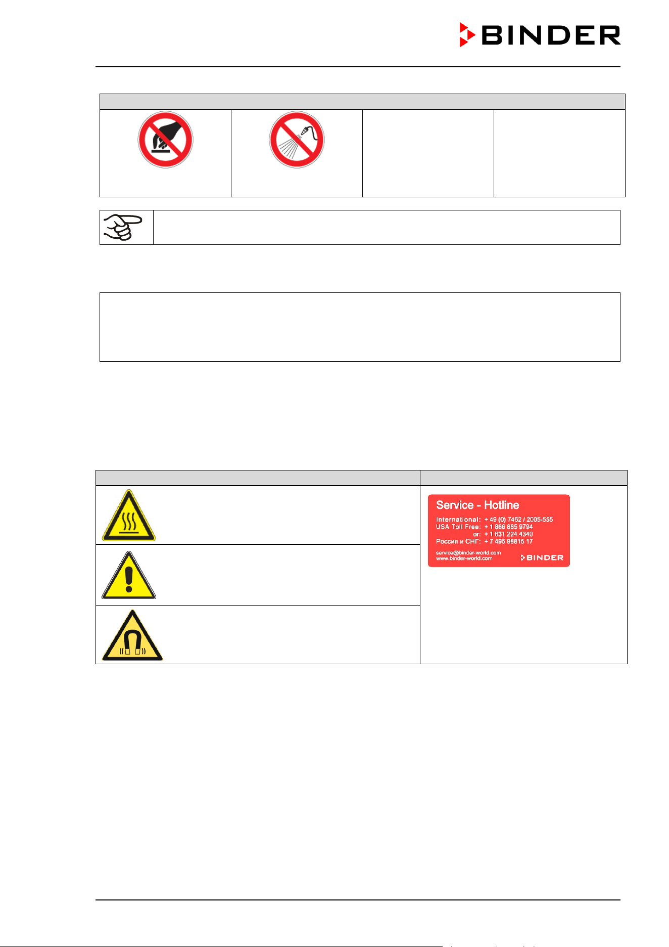
1.5 Localization / position of safety labels on the chamber
The following labels are located on the chamber:
Pictograms (Warning signs)
Service label
Hot surface
• on the outer chamber door
Risk of injury
• on the outer door: CB-UL / CBF-UL only
• above the access ports (option)
Magnetic field
• on the outer door above the door handle
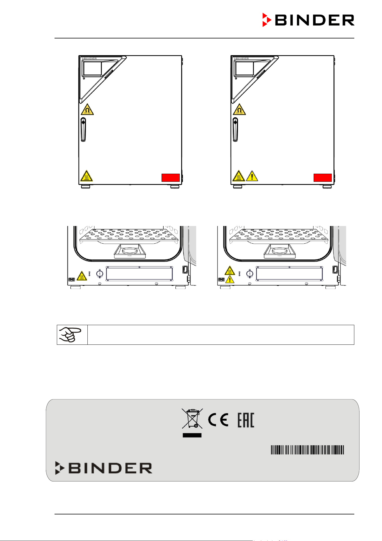
CB / CB-UL, CBF / CBF-UL (E7) 07/2022 Page 12/199
CO
2
incubator CB / CBF CO
2
incubator CB-UL / CBF-UL
Figure 1: Position of labels on the chamber
CO
2
incubator CBF CO
2
incubator CBF-UL
Figure 2: Position of additional labels on the CBF / CBF-UL
Keep safety labels complete and legible.
Replace safety labels that are no longer legible. Contact BINDER service for these replacements.
1.6 Type plate
Position of type plate: left chamber side (seen from front), at the bottom in the middle
Figure 3: Type plate (example of CB 170 regular chamber)
Nominal temp.
180 °C
1,30 kW / 5,7 A
356 °F
200-230 V / 50 Hz
IP protection
20
200-230 V / 60 Hz
Safety device
DIN 12880
1 N ~
Class
3.1
Art. No.
9640-0009
Var. 9640-0000
Project No.
Built
2022
CO2 incubator
BINDER GmbH
Im Mittleren Ösch 5
78532 Tuttlingen / Germany
www.binder-world.com
CB 170
E7
Serial No. 00000000000000
Made in Germany
CB / CB-UL, CBF / CBF-UL (E7) 07/2022 Page 13/199
Indications of the type plate (example)
Indication
Information
BINDER
Manufacturer: BINDER GmbH
CB 170
Model designation
CO2 incubator
Device name
Serial No.
00000000000000
Serial no. of the chamber
Built
2022
Year of construction
Nominal
temperature
180 °C
356 °F
Nominal temperature
IP protection
20
IP type of protection acc. to standard EN 60529
Temp. safety device
DIN 12880
Temperature safety device acc. to standard DIN 12880
Class
3.1
Class of temperature safety device
Art. No.
9640-0009
Art. No. of the chamber
Var.
9640-0025
Variant No. / Equipment
Project No.
---
Optional: Special application acc. to project no.
1,30 kW
Nominal power
200-230 V / 50 Hz
Nominal voltage range +/-10%
at the indicated power frequency
200-230 V / 60 Hz
1 N ~
Current type
5,7 A
Nominal current
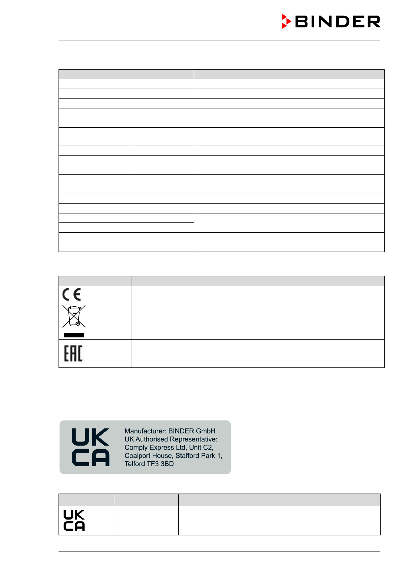
Symbols on the type plate
Symbol
Information
CE conformity marking
Electrical and electronic equipment manufactured / placed on the market in the
EC after 13 August 2005 and to be disposed of in separate collection according
to Directive 2012/19/EU on waste electrical and electronic equipment (WEEE).
The chamber is certified according to Customs Union Technical Regulation (CU
TR) for the Eurasian Economic Union (Russia, Belarus, Armenia, Kazakhstan
Kyrgyzstan).
1.7 UKCA Label
The sticker with UKCA Authorised Representative details sticks next to the type plate to the left side of the
chamber, bottom right-hand.
Figure 4: UKCA Label
Symbol on the sticker
Symbol Applies to Information
All models except
UL models
UKCA conformity marking
CB / CB-UL, CBF / CBF-UL (E7) 07/2022 Page 14/199
1.8 General safety instructions on installing and operating the CO
2
incubator
With regard to operating the chamber and to the installation location, please observe the local and national
regulations relevant for your country (for Germany: DGUV guidelines 213-850 on safe working in
laboratories, issued by the employers’ liability insurance association).
BINDER GmbH is only responsible for the safety features of the chamber provided skilled electricians or
qualified personnel authorized by BINDER perform all maintenance and repair, and if components relating
to chamber safety are replaced in the event of failure with original spare parts.
To operate the chamber, use only original BINDER accessories or accessories from third-party suppliers
authorized by BINDER. The user is responsible for any risk caused by using unauthorized accessories.
NOTICE
Danger of overheating due to lack of ventilation.
Damage to the chamber.
∅ Do NOT install the chamber in unventilated recesses.
Ensure sufficient ventilation for dispersal of the heat.
Observe the prescribed minimum distances when installing the chamber (chap. 3.4).
Do not install or operate the chamber in hazardous locations.
DANGER
Danger of explosion due to combustible dusts or explosive mixtures in the vicinity
of the chamber.
Serious injury or death from burns and / or explosion pressure.
∅ Do NOT operate the chamber in potentially explosive areas.
KEEP combustible dust or air-solvent mixtures AWAY from the chamber.
The chamber does not dispose of any measures of explosion protection.
DANGER
Danger of explosion due to introduction of flammable or explosive substances in
the chamber.
Serious injury or death from burns and / or explosion pressure.
∅ Do NOT introduce any substance into the chamber which is combustible or explosive at
working temperature.
∅ Do NOT introduce any combustible dust or air-solvent mixture in the inner chamber.
Any solvent contained in the charging material must not be explosive or inflammable. I.e., irrespective of
the solvent concentration in the steam room, NO explosive mixture with air must form. The temperature
inside the chamber must lie below the flash point or below the sublimation point of the charging material.
Familiarize yourself with the physical and chemical properties of the charging material, as well as the
contained moisture constituent and its behavior with the addition of heat energy and humidity (CBF / CBF-
UL).
Familiarize yourself with any potential health risks caused by the charging material, the contained moisture
constituent or by reaction products which may arise during the temperature process. Take adequate
measures to exclude such risks prior to putting the chamber into operation.
CB / CB-UL, CBF / CBF-UL (E7) 07/2022 Page 15/199
WARNING
Danger of intoxication and infection through contamination of the chamber with
toxic, infectious or radioactive substances.
Damages to health.
Protect the interior of the chamber from contamination by toxic, infectious or radioactive
substances.
Take suitable protective measures when introducing and removing toxic, infectious or
radioactive material
DANGER
Electrical hazard by water entering the chamber.
Deadly electric shock.
∅ The chamber must NOT become wet during operation, cleaning, or maintenance.
∅ Do NOT install the chamber in damp areas or in puddles.
Set up the chamber in a splash-proof manner.
The chambers were produced in accordance with VDE regulations and were routinely tested in accordance
to VDE 0411-1 (IEC 61010-1).
During and after a sterilization the temperature of the inner surfaces almost equals the set-point. The inner
doors, the inner door and glass door handles, and the inner chamber will become hot during a sterilization.
CAUTION
Danger of burning by touching hot chamber parts during or after a sterilization.
Burns.
∅ Do NOT touch the inner surfaces, inner doors, inner door handles, and door gaskets
during or after a sterilization.
WARNING
Danger of injury and damages by the chamber tipping over.
Injuries and damage to the chamber and the charging material
∅ Do NOT load the chamber door with heavy objects while it is open.
The chamber is equipped with a permanent magnet located behind the inner panel of the outer chamber
door. If persons with active implants (e.g. pacemakers, defibrillators) keep a sufficient safe distance
(distance of field source to implant), an influence of these implants can be excluded with high probability.
WARNING
Magnets can affect the function of pacemakers and implanted defibrillators.
A pacemaker can be put into test mode and cause discomfort. A defibrillator may
not work anymore.
If you wear such devices, maintain a sufficient safety distance to the chamber door in the
area of the door handle.
Warn wearers of such devices of approaching the chamber door.
CB / CB-UL, CBF / CBF-UL (E7) 07/2022 Page 16/199
1.9 Precautions when working with gases
Notes on handling carbon dioxide (CO
2
)
Carbon dioxide (CO
2
) in high concentrations is hazardous to health. It is colorless and almost odorless and
therefore practically imperceptible. Vent out any CO
2
gas that may escape via good room ventilation or a
suitable connection to an exhaust system. We recommend installing a CO
2
warning system.
DANGER
Danger of suffocation and poisoning by high concentration of CO
2
(> 4 Vol.-%).
Death by suffocation.
∅ Do NOT set up chambers in non-ventilated recesses.
Ensure technical ventilation measures.
Observe the relevant regulations for handling CO
2
.
Close the CO
2
supply when decommissioning the chamber.
Chamber with O
2
control: Notes on handling oxygen (O
2
)
Oxygen (O
2
) is colorless and almost odorless and therefore practically imperceptible. It promotes burns,
which can proceed explosively. There is a fire hazard for flammable oxygenated materials, e.g. clothes and
hair. O
2
is heavier than air and may accumulate in low-lying areas.
DANGER
Danger of fire and explosion through contact of combustible materials with O
2
with high concentration of O
2
(> 21 % O
2
).
Serious injury or death from burns and / or explosion pressure.
∅ Do NOT set up chambers in non-ventilated recesses.
Ensure technical ventilation measures.
Observe the relevant regulations for handling O
2
.
Close the O
2
supply when decommissioning the chamber.
Take appropriate measures to prevent oxygen enrichment and fire and explosion hazards in areas where
oxygen enrichment is possible.
CB / CB-UL, CBF / CBF-UL (E7) 07/2022 Page 17/199
General information for safe handling of oxygen:
• Make sure training of personnel on hazards of oxygen enrichmen
t and necessary safety
measures.
• Make sure adequate labeling of all oxygen equipment and facilities.
•
Make sure gas tightness of all gas connections by checking them for leaks (e.g. with leak
spray or diluted soap solution).
• Close the main valve of the source of oxygen after work when not using the chamber.
• Never lubricate O
2
equipment with oil or fat. Use only materials and spare parts which are
approved for use with oxygen.
• Regularly inspect fire extinguishers for proper condition.
• Set up emergency showers where oxygen enrichment is possible.
• Strictest smoking ban and no ignition sources in areas where oxygen enrichment is possible.
•
Make sure good ventilation of areas where oxygen enrichment is possible (location of the
chamber and/or O
2
cylinders.
• Persons who may have been in a possibly oxygen-enriched atmosphere
must keep away
from ignition sources (flames, cigarettes, etc.) and ventilate their clothes at least 15 minutes.
• Always keep emergency routes free.
Chamber with O
2
control: Notes on handling nitrogen (N
2
)
Nitrogen (N
2
) in high concentrations is hazardous to health. It is colorless and almost odorless and therefore
practically imperceptible. Any N
2
gas that may escape must be safely led out via good room ventilation or
a suitable connection to an exhaust system.
DANGER
Risk of suffocation through high concentration of N
2
.
Death by suffocation.
∅ Do NOT set up chambers in non-ventilated recesses.
Ensure technical ventilation measures.
Observe the relevant regulations for handling N
2
.
Close the N
2
supply when decommissioning the chamber.
1.10 Precautions when handling gas cylinders
General information for safe handling of gas cylinders:
• Store and use gas cylinders only in well-ventilated locations.
• Open the gas cylinder valve slowly to avoid pressure surges.
• Secure gas cylinders during storage and use against falling (chaining).
• Transport gas cylinders with a cylinder cart, do not carry, roll, or throw them.
• Always close the valve even with apparently empty cylinders; screw on the cap when not in
use. Return gas cylinders with the valve closed.
• Do not open gas cylinders by force. Mark them when damaged.
• Protect gas cylinders against fire, e.g. do not store together with flammable liquids.
• Observe relevant regulations for dealing with gas cylinders.
CB / CB-UL, CBF / CBF-UL (E7) 07/2022 Page 18/199
Secure the gas cylinders against falling and other mechanical damage.
WARNING
Risk of injury through sudden release of the stored pressure energy when the valve
safety is torn off.
Injuries.
Secure gas cylinders against falling (chaining).
Transport gas cylinders with a cylinder cart.
The valve of the gas cylinder always must be closed before screwing on or unscrewing the gas hose.
WARNING
Risk of injury through sudden release of the stored pressure energy when opening
the cylinder valve of a not connected cylinder.
Injuries.
Close the gas cylinder valve before connecting or removing the gas hose.
After connecting the gas cylinder, check all gas connections for leaks (e.g. with leak spray or
diluted soap solution).
1.11 Intended use
Following the instructions in this operating manual and conducting regular maintenance work
(chap. 22.5) are part of the intended use.
Any use of the chambers that does not comply with the requirements specified in this Operating
Manual shall be considered improper use.
Other applications than those described in this chapter are not approved.
Use
CB / CB-UL and CBF / CBF-UL incubators are suitable for the cultivation of mammal cells under typical
conditions of approx. 37 °C / 98.6°F. The chamber permits setting defined pH conditions by common
NaHCO
3
buffer systems of commercial cell media by keeping an exact CO
2
atmosphere inside. The
chambers guarantee high humidity inside to avoid osmolarity increasing caused by the evaporation of the
cell media.
With the chamber with O
2
control, a variable oxygen atmosphere can additionally influence the growth of
the cells.
The chambers are suitable for exact conditioning of harmless materials.
Requirements for the chamber load
Any solvent must not be explosive and flammable. Components of the charging material must NOT form
an explosive mixture with air. The operating temperature must lie below the flash point or below the
sublimation point of the charging material. Any component of the charging material must NOT be able to
release toxic gases.
The charging material shall not contain any corrosive ingredients that may damage the machine
components made of stainless steel, aluminum, and copper. Such ingredients include in particular acids
and halides. Any corrosive damage caused by such ingredients is excluded from liability by BINDER GmbH.
CB / CB-UL, CBF / CBF-UL (E7) 07/2022 Page 19/199
The chamber does not dispose of any measures of explosion protection.
DANGER
Explosion or implosion hazard and danger of poisoning through the introduction of
unsuitable loading material.
Poisoning. Serious injury or death from burns and / or explosion pressure.
∅ Do NOT introduce any substance combustible or explosive at working temperature into
the chamber, in particular no energy sources such as batteries or lithium-ion batteries.
∅ NO explosive dust or air-solvent mixture in the inner chamber.
∅ Do NOT introduce any substance which could lead to release of toxic gases.
Contamination of the chamber by toxic, infectious or radioactive substances must be prevented
WARNING
Danger of intoxication and infection through contamination of the chamber with
toxic, infectious or radioactive substances.
Damages to health.
Protect the interior of the chamber from contamination by toxic, infectious or radioactive
substances.
Take suitable protective measures when introducing and removing toxic, infectious or
radioactive material
In case of foreseeable use of the chamber there is no risk for the user through the integration of the chamber
into systems or by special environmental or operating conditions in the sense of EN 61010-1:2010. For this,
the intended use of the chamber and all its connections must be observed.
Medical devices
The chambers are not classified as medical devices as defined by Regulation (EU) No 2017/745.
Due to the special demands of the Medical Products legislation, these chambers are not
qualified to perform sterilization of medical devices as defined by Regulation (EU) No
2017/745.
Personnel Requirements
Only trained personnel with knowledge of the Operating Manual can set up and install the chamber, start it
up, operate, clean, and take it out of operation. Service and repairs call for further technical requirements
(e.g. electrical know-how), as well as knowledge of the service manual.
Installation site requirements
The chambers are designed for setting up inside a building (indoor use).
The requirements described in the Operating Manual for installation site and ambient conditions (Chap.
3.4) must be met.
WARNING: If customer should use a BINDER chamber running in non-supervised
continuous operation, we strongly recommend in case of inclusion of irrecoverable specimen
or samples to split such specimen or samples and store them in at least two chambers, if
this is feasible.
Relevant regulations for dealing with CO
2
/ O
2
/ N
2
and gas cylinders must be observed.

CB / CB-UL, CBF / CBF-UL (E7) 07/2022 Page 20/199
1.12 Foreseeable Misuse
Other applications than those described in chap. 1.11 are not approved.
This expressly includes the following misuses (the list is not exhaustive), which pose risks despite the
inherently safe construction and existing technical safety equipment:
• Non-observance of Operating Manual
• Non-observance of information and warnings on the chamber (e.g. control unit messages, safety
identifiers, warning signals)
• Installation, startup, operation, maintenance and repair by untrained, insufficiently qualified, or
unauthorized personnel
• Missed or delayed maintenance and testing
• Non-observance of traces of wear and tear
• Insertion of materials excluded or not permitted by this Operating Manual.
• Non-compliance with the admissible parameters for processing the respective material.
• Failure to comply with the relevant regulations for handling gas cylinders
• Failure to comply with the relevant regulations for handling CO
2
, O
2
or N
2
• Operation of the chamber without ventilation measures
• Installation, testing, service or repair in the presence of solvents
• Installation of replacement parts and use of accessories and operating resources not specified and
authorized by the manufacturer
• Installation, startup, operation, maintenance or repair of the chamber in absence of operating
instructions
• Bypassing or changing protective systems, operation of the chamber without the designated protective
systems
• Non-observance of messages regarding cleaning and disinfection of the chamber.
• Spilling water or cleaning agent on the chamber, water penetrating into the chamber during operation,
cleaning or maintenance.
• Cleaning activity while chamber is turned on.
• Operation of the chamber with a damaged housing or damaged power cord.
• Continued operation of the chamber during an obvious malfunction
• Insertion of objects, particularly metallic objects, in louvers or other openings or slots on the chamber
• Human error (e.g. insufficient experience, qualification, stress, exhaustion, laziness)
To prevent these and other risks from incorrect operation, it is recommended the operator issue operating
instructions and standard operating procedures (SOPs).
1.13 Residual Risks
The unavoidable design features of a chamber, as well as its proper field of application, can also pose risks,
even during correct operation. These residual risks include hazards which, despite the inherently safe
design, existing technical protective equipment, safety precautions and supplementary protective
measures, cannot be ruled out.
Messages on the chamber and in the Operating Manual warn of residual risks. The consequences of these
residual risks and the measures required to prevent them are listed in the Operating Manual. Moreover, the
operator must take measures to minimize hazards from unavoidable residual risks. This includes, in
particular, issuing operating instructions.

CB / CB-UL, CBF / CBF-UL (E7) 07/2022 Page 21/199
The following list summarizes the hazards against which this Operating Manual and the Service Manual
warn, and specifies protective measures at the appropriate spots:
Unpacking, Transport, Installation
• Sliding or tilting the chamber
• Setup of the chamber in unauthorized areas
• Installation of a damaged chamber
• Installation of a chamber with damaged power cord
• Inappropriate site of installation
• Missing protective conductor connection
Normal operation
• Assembly errors
• Contact with hot surfaces on the housing
• Contact with hot surfaces in the interior and inside of doors
• Emission of non-ionizing radiation from electrical operating resources
• Contact with live parts in normal state
Cleaning and Decontamination
• Penetration of water into the chamber
• Inappropriate cleaning and decontamination agents
• Enclosure of persons in the interior
Malfunction and Damage
• Continued operation of the chamber during an obvious malfunction or outage of the heating, gas, or
humidifying systems
• Contact with live parts during error status
• Operation of a unit with damaged power cord
Maintenance
• Maintenance work on live parts.
• Execution of maintenance work by untrained/insufficiently qualified personnel
• Electrical safety analysis during annual maintenance not performed
Trouble-shooting and Repairs
• Non-observance of warning messages in the Service Manual
• Trouble-shooting of live parts without specified safety measures
• Absence of a plausibility check to rule out erroneous inscription of electrical components
• Performance of repair work by untrained/insufficiently qualified personnel
• Inappropriate repairs which do not meet the quality standard specified by BINDER
• Use of replacement parts other than BINDER original replacement parts
• Electrical safety analysis not performed after repairs
CB / CB-UL, CBF / CBF-UL (E7) 07/2022 Page 22/199
1.14 Operating instructions
Depending on the application and location of the chamber, it is recommended that the operator of the
chamber provides the relevant information for safe operation of the chamber in a set of operating
instructions.
Keep these operating instructions with the chamber at all times in a place where they are
clearly visible. They must be comprehensible and written in the language of the employees.
1.15 Measures to prevent accidents
The operator of the chamber must observe the local and national regulations and take precautions to
prevent accidents.
The manufacturer took the following measures to prevent dangers:
• Indications on the type plate
See operating manual chap. 1.6.
• Operating manual
An operating manual is available for each chamber.
• Overtemperature monitoring
The chamber is equipped with a temperature display, which can be read from outside.
The chamber is equipped with an additional safety controller (temperature safety device class 3.1 acc.
to DIN 12880:2007). Visual and audible (buzzer) signals indicate temperature exceeding.
• Safety, measurement, and control equipment
The safety, measuring, and control equipment is easily accessible.
• Electrostatic charge
The interior parts are grounded.
• Non-ionizing radiation
Non-ionizing radiation is not intentionally produced, but released only for technical reasons by electrical
equipment (e.g. power cables). The chamber is equipped with a permanent magnet located behind the
inner panel of the outer chamber door. If persons with active implants (e.g. pacemakers, defibrillators)
keep a sufficient safe distance (distance of field source to implant), an influence of these implants can
be excluded with high probability.
WARNING
Magnets can affect the function of pacemakers and implanted defibrillators.
A pacemaker can be put into test mode and cause discomfort. A defibrillator
may not work anymore.
If you wear such devices, maintain a sufficient safety distance to the chamber door
in the area of the door handle.
Warn wearers of such devices of approaching the chamber door.
• Protection against touchable surfaces
Tested according to EN ISO 13732-1:2008.
• Floors
See operating manual chap. 3.4 for correct installation
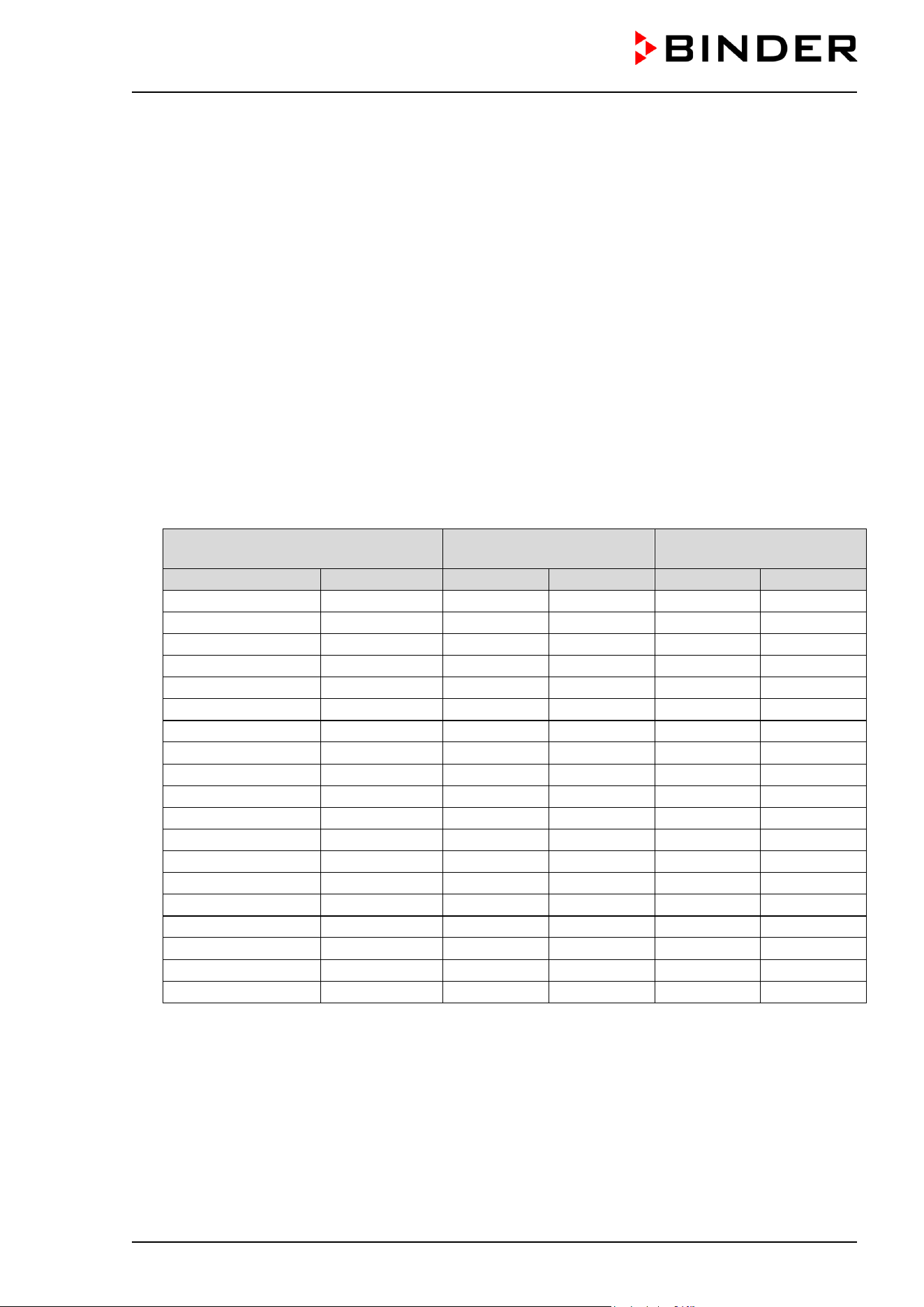
CB / CB-UL, CBF / CBF-UL (E7) 07/2022 Page 23/199
• Cleaning
See operating manual chap. 21.
1.16 CBF / CBF-UL : Resistance of the humidity sensor against harmful
substances
The following list of harmful substances refers only to the humidity sensor and does not include any other
materials incorporated in the chamber or prohibited substances in relation to explosion protection.
Some gases - especially clean gases - do not have any influence on the humidity sensor. Others do have
a very small influence, whereas others may influence the sensor to a larger extent.
• The following gases do not influence the sensor and the humidity measurement: Argon (Ar), carbon
dioxide (CO
2
),helium (He), hydrogen (H
2
), neon (Ne), nitrogen (N
2
), nitrous oxide (N
2
O), oxygen (O
2
)
• The following gases do not or to a minor extent influence the sensor and the humidity measurement:
Butane (C
4
H
10
), ethane (C
2
H
6
), methane (CH
4
), natural gas propane (C
3
H
8
)
• The following gases do not, or to a minor extent influence the sensor and the humidity measurement,
provided that the indicated loads are not exceeded:
Maximum work place
threshold limit value
Tolerated concentration
with permanent load
Substance
Formula
ppm
mg/m
3
ppm
mg/m
3
Ammonia
NH
3
20
14
5500
4000
Acetone
CH
3
COCH
3
500
1200
3300
8000
Benzene
300
1200
150000
Chlorine
Cl
2
0.5
1.5
0.7
2
Acetic acid
CH
3
COOH
10
25
800
2000
Ethyl acetate
CH
3
COOC
2
H
5
400
1400
4000
15000
Ethanol
C
2
H
5
OH
500
960
3500
6000
Ethylene glycol
HOCH
2
CH
2
OH
10
26
1200
3000
Formaldehyde
HCHO
0.3
0.37
2400
3000
Isopropanol
(CH
3
)
2
CHOH
200
500
4800
12000
Methanol
CH
3
OH
200
260
3500
6000
Methyl ethyl ketone
C
2
H
5
COCH
3
200
590
3300
8000
Ozone
O
3
0.1
0.2
0.5
1
Hydrochloric acid
HCl
2
3
300
500
Hydrogen sulphide
H
2
S
10
15
350
500
Nitrogen oxides
NOx
5
9
5
9
Sulphur dioxide
SO
2
5
13
5
13
Toluol
C
6
H
5
CH
3
100
380
1300
5000
Xylene
C
6
H
4
(CH
3
)
2
100
440
1300
5000
These values are to be considered as approximate values. The sensor resistance largely depends on
the temperature and humidity conditions during the time of exposure to harmful substances. Avoid
simultaneous condensation. Tolerated error of measurement: ± 2 %r.H. The maximum work place
threshold limit value is one that can be regarded as harmless for humans.
• Vapors of oil and fat are dangerous for the sensor because they may condensate at the sensor and thus
prevent its function (insulating layer). For similar reasons it is not possible to measure smoke gases.

CB / CB-UL, CBF / CBF-UL (E7) 07/2022 Page 24/199
2. Chamber description
The CO
2
incubators CB / CB-UL and CBF / CBF-UL are equipped with a multifunctional microprocessor
display controller for temperature, CO
2
, and O
2
(chamber with O
2
control) levels and humidity (CBF / CBF-
UL) and a digital display accurate to one-tenth of a degree resp. 0.1 vol.-%. With its comprehensive program
control functions, the display program controller MB2 permits the high precision performance of
temperature, CO
2
, O
2
(chamber with O
2
control), and humidity (CBF / CBF-UL) cycles.
Material: The inner chamber, the pre-heating chamber and the inside of the doors are all made of stainless
steel V2A (German material no. 1.4301, US equivalent AISI 304). The inner surfaces are smooth and
therefore easy to clean. The inner chamber is deep-drawn from one piece, polished (suitable for
pharmaceutical applications) and has no welds or inaccessible corners. The hinges and the seal of the
inner glass door are glued from the outside to aid cleaning of the inner chamber. When operating the
chamber at high temperatures (sterilization), the impact of the oxygen in the air may cause discoloration of
the metallic surfaces (yellowish-brown or blue) by natural oxidation processes. These colorations are
harmless and will in no way impair the function or quality of the chamber. The perforated shelves are also
made of stainless steel. You can insert a maximum of 3 (chamber size 56), 6 (chamber size 170), resp. 8
(chamber size 220) shelves. The housing is RAL 7035 powder-coated. All corners and edges are also
completely coated.
Door lock: The DuoDoor™ door lock offers two to open the outer door and glass door independently or
together. The outer door is regularly equipped with a door lock with keys. The standard chamber door is
hinged right. The chamber is optionally available with door hinged left.
Sterilization: The chamber’s heating system permits hot-air auto-sterilization at a setpoint of 180 °C /
356 °F. Thus, the effective sterilization temperature is maintained for at least two hours on all internal
surfaces, resulting in sterilization of the entire inner chamber. The effectiveness of the sterilization has also
been confirmed by an independent research institute.
Temperature safety device Thanks to the regular safety controller (temperature safety device class 3.1
acc. to DIN 12880:2007), the set temperature is maintained in case of failure.
CO
2
system: A highly precise, drift-free CO
2
infrared measuring system in combination with the permanent
mixture of CO
2
gas through a special proprietary gas mixing head developed by BINDER allows precise
and constant CO
2
concentrations for long periods. This creates optimum growth conditions for cultures.
The gas enters the chamber via a fine filter (aseptic filter) with a high filtration efficiency that also filters the
smallest particles.
Fast reaction times, maximum accuracy and selectivity characterize the CO
2
measuring procedure of the
CO
2
incubators. The accuracy of the CO
2
measuring system is based on an infrared measuring cell with
NDIR (non-dispersive infrared) sensor, which continuously regulates to a reference value. Therefore,
disturbance variables and aging phenomena in the measuring system are almost completely eliminated,
so that this measuring system, in contrast to other measuring procedures, remains practically drift-free
between calibrations and is entirely selective for CO
2
. The sensor is built into the chamber and can be
sterilized.
O
2
control (chamber with O
2
control): The CO
2
incubator is available with O
2
control in addition to CO
2
control. There are two different control ranges:
• Regular equipment: Hypoxic control range 0.2 to 20 vol. % O
2
. Only N
2
can be connected to reduce O
2
concentration; it is not possible to connect O
2
gas bottles to increase O
2
concentration. Control in the
low O
2
range is very precise, in particular in the range below 1 vol. % O
2
.
• Alternative control range 10 to 95 vol. % O
2
(option). Although the high control range is intended in
particular for hyperoxic applications (> 21 vol. % O
2
), it is also suitable for slightly hypoxic applications
between 10 and 20 vol. % O
2
.
The O
2
sensor is a semiconductor gas sensor with ZrO
2
ceramic.
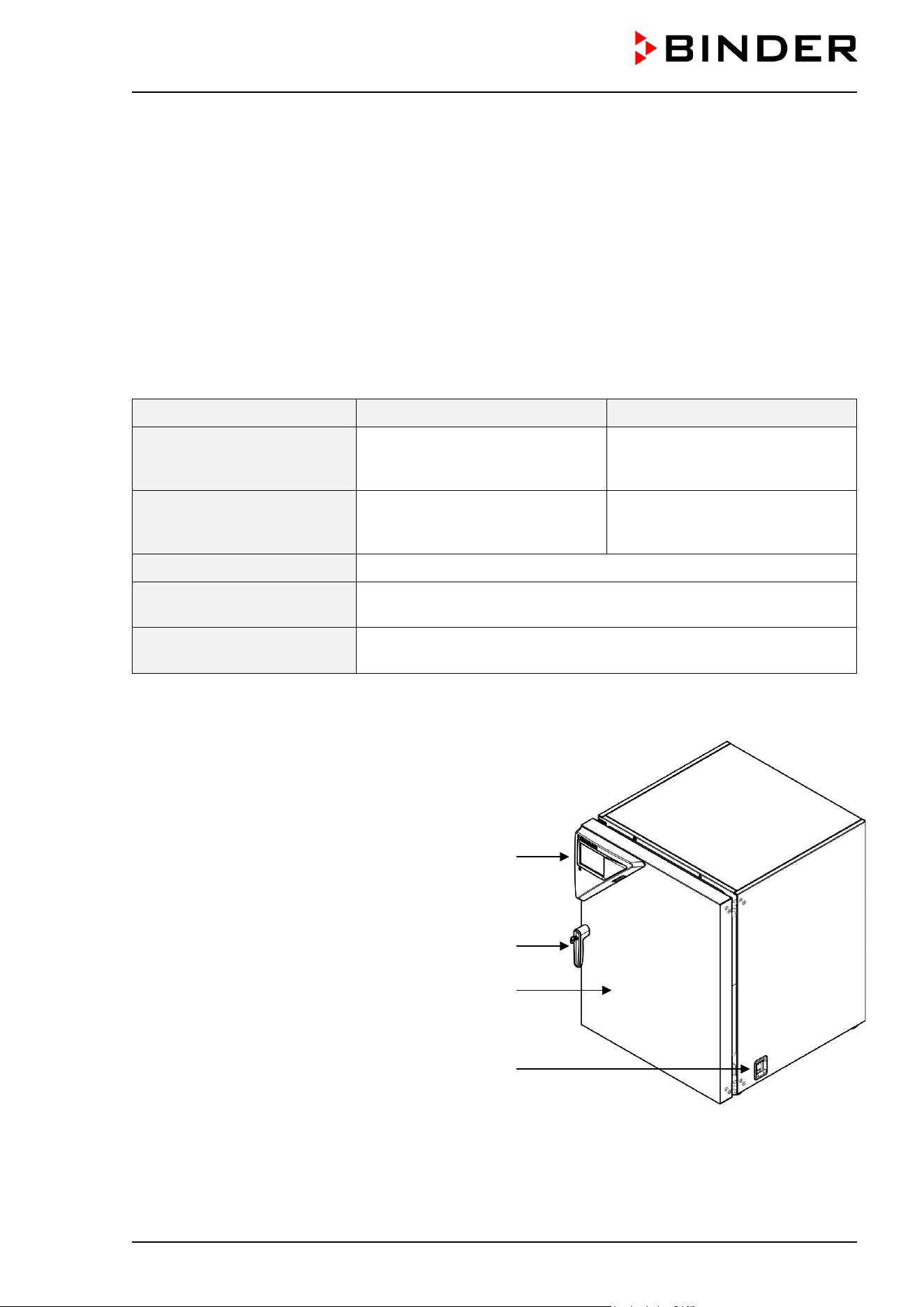
CB / CB-UL, CBF / CBF-UL (E7) 07/2022 Page 25/199
CBF / CBF-UL humidity control: The chamber is equipped with humidity control and a microprocessor-
controlled humidification system.
Freshwater is supplied by manually filling a freshwater bag, which is placed behind the chamber door in a
recess.
A resistance humidifying system humidifies the air. For this purpose, use deionized (demineralized) water.
The option BINDER Pure Aqua Service allows using the chamber with any degree of water hardness.
Controller: The efficient program controller is equipped with a multitude of operating functions, in addition
to recorder and alarm functions. Programming of test cycles is easily accomplished via the modern MB2
touch screen controller and is also possible directly with a computer via Intranet in connection with the APT-
COM™ 4 Multi Management Software (option, chap. 18.1). The chambers are equipped with an Ethernet
interface for computer communication. The APT-COM™ 4 Multi Management Software permits networking
up to 30 chambers and connecting them to a PC for controlling and programming, as well as recording and
representing temperature, CO
2
and O
2
and humidity data. For further options, see chap. 24.5.
CB / CB-UL CBF / CBF-UL
Temperature range:
4 °C / 7.2 °F above ambient
temperature up to +60 °C / 140 °F
5 °C / 9 °F above ambient
temperature up to +60 °C /
140 °F
Temperature range
(chamber with O
2
control):
6 °C / 10.8 °F above ambient
temperature up to +60 °C / 140 °F
7 °C / 12.6 °F above ambient
temperature up to +60 °C /
140 °F
CO
2
range: 0 vol.-% up to 20 vol.-%
O
2
range
(chamber with O
2
control):
0.2 vol.-% up to 20 vol.-% (hypoxic control range)
or 10 vol.-% up to 95 vol.-% (optional alternative control range)
Humidity range
(CBF / CBF-UL):
50 % r.h. up to 95 % r.h.
2.1 Chamber overview
Instrument panel with microprocessor controller
T4.12 and USB interface
Door handle
Chamber door
Main power switch
Figure 5: CO
2
incubator (example: model CB 170)
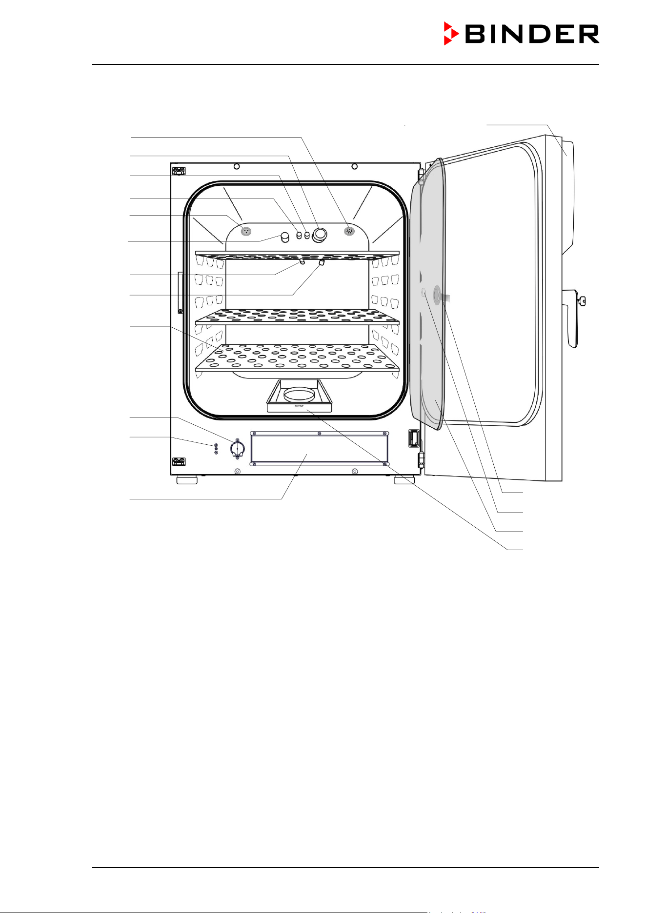
CB / CB-UL, CBF / CBF-UL (E7) 07/2022 Page 26/199
2.2 Inner chamber
Figure 6: CBF 170 with O
2
control and options
(A) Instrument panel with microprocessor program controller MB2, indicating temperature, CO
2
, O
2
(chamber with O
2
control) and humidity (CBF / CBF / CBF-UL)
(B) Connection socket for extra-low voltage supply (option, chap. 18.6)
(C) CO
2
sensor
(D) Gas mixing head CO
2
(D2) Additional gas mixing head O
2
/ N
2
(chamber with O
2
control)
(E) Pt 100 temperature probe
(F) O
2
sensor (chamber with O
2
control)
(G) Humidity sensor (CBF / CBF-UL)
(H) Internal socket 230V (max. 3 A) (option, available via BINDER INDIVIDUAL Customized Solutions,
chap. 18.4)
(I) Perforated shelves, made of stainless steel
(J) Glass door handle
(K) Measuring access port
(L) Inner glass doors
(M) Permadry™ water pans
(K)
(
J)
(
L)
(M)
(A)
(B)
(C)
(D)
(D2)
(H)
(F)
(E)
(G)
(I)
(N)
(O)
(P)
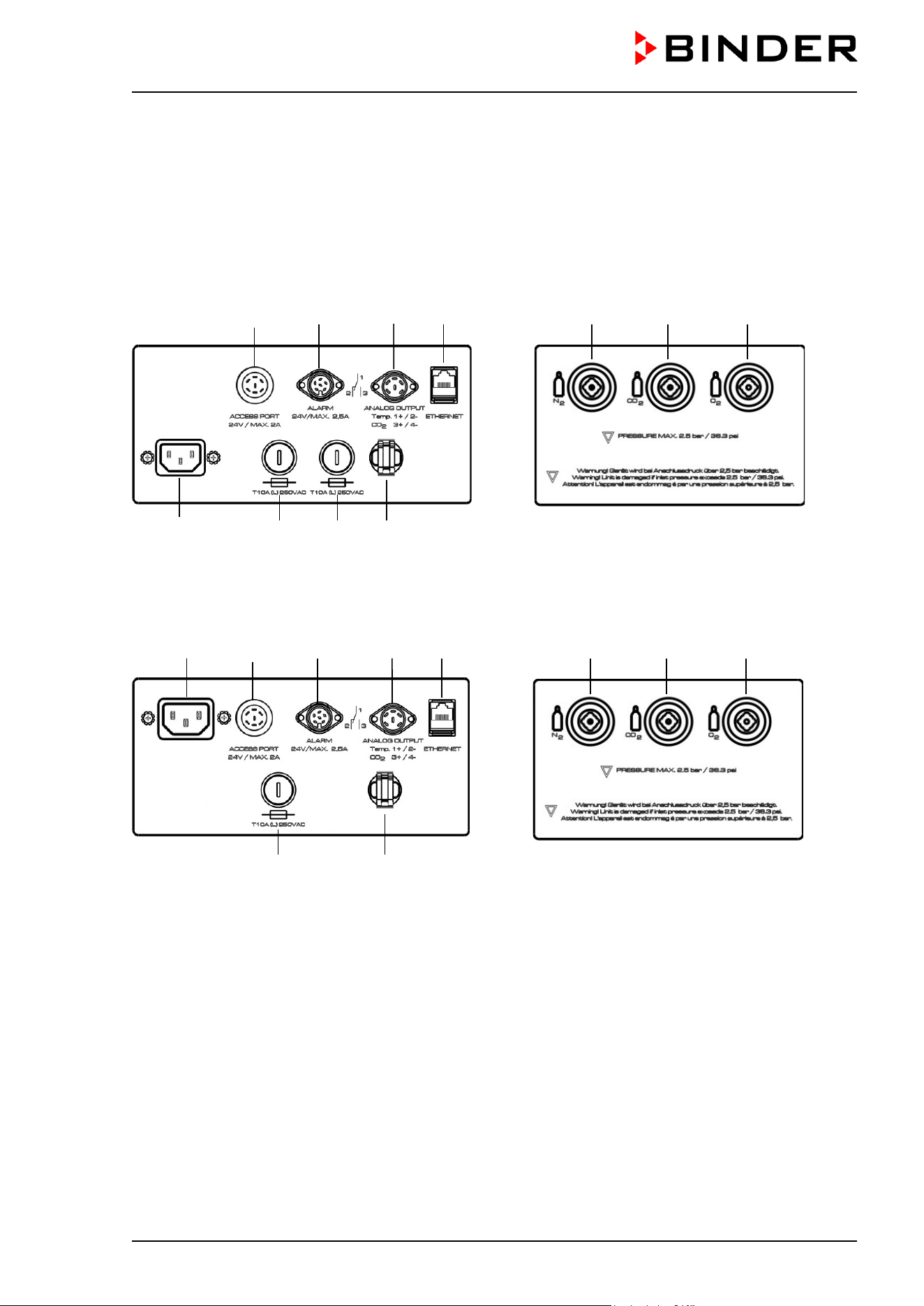
CB / CB-UL, CBF / CBF-UL (E7) 07/2022 Page 27/199
(N) Pump (CBF / CBF-UL)
(O) Water connection for silicone tube (CBF / CBF-UL)
(P) Opening for freshwater bag (CBF / CBF-UL)
2.3 Control panel on the rear of the chamber
(2) (3) (4) (5) (9) (10) (11)
(1b) (6b) (7) (8)
Figure 7: Rear control panel CB with O
2
control and options
(1b) (2) (3) (4) (5) (9) (10) (11)
(6a) (8)
Figure 8: Rear control panel CB-UL with O
2
control and options
(1a) Socket for IEC connector plug / power cable 100-120 V AC
(1b) Socket for IEC connector plug / power cable 230 V AC
(2) External socket for extra-low voltage supply (option for chamber size 170 / 220, chap. 18.6)
(3) DIN-socket for zero-voltage relay alarm outputs
(4) DIN socket for analog outputs 4-20 mA (option, chap. 18.5)
(5) Ethernet interface for computer communication
(6a) Miniature fuse T12,5 A (L) 250 V AV for 100-120 V chamber
(6b) Miniature fuse T10 A (L) 250 V AC for 200-230 V chamber
(7) Miniature fuse T10 A (L) 250 V AC for 200-230 V chamber
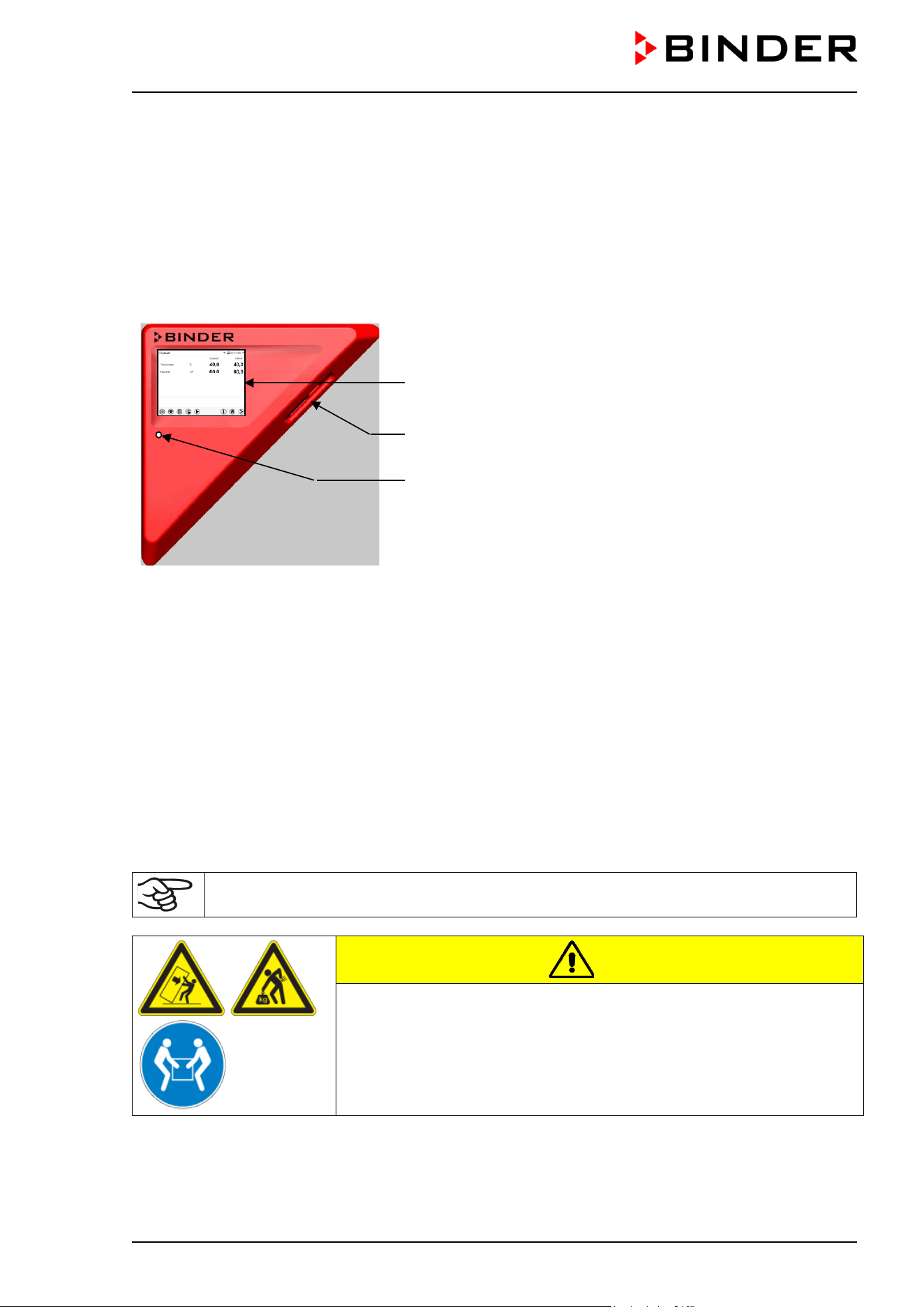
CB / CB-UL, CBF / CBF-UL (E7) 07/2022 Page 28/199
(8) Strain relief for power cable
(9) Quick acting closure socket for N
2
(chamber with O
2
control)
(10) Quick acting closure socket for CO
2
(11) Quick acting closure socket for O
2
(chamber with O
2
control with optional alternative control range
10 up to 95 vol.-% O
2
)
2.4 Instrument panel
MB2 controller display
5,7" with touchscreen
USB interface
Pilot lamp
Figure 9: Instrument panel with MB2 program controller and USB
interface
3. Completeness of delivery, transportation, storage, and
installation
3.1 Unpacking, and checking equipment and completeness of delivery
After unpacking, please check the chamber and its optional accessories, if any, based on the delivery
receipt for completeness and for transportation damage. Inform the carrier immediately if transportation
damage has occurred.
The final tests of the manufacturer may have caused traces of the shelves on the inner surfaces. This has
no impact on the function and performance of the chamber.
Please remove any transportation protection devices and adhesives in/on the chamber and on the doors
and remove the operating manuals and accessory equipment.
Remove any protective lamination sheet on the inner metal surfaces prior to commissioning.
CAUTION
Risk of injury and damages by lifting heavy loads and by sliding or
tilting of the chamber due to improper lifting.
Injuries, damage to the chamber.
∅ Do NOT lift or transport the chamber using the door handle or the door.
Lift the chamber
from the pallet at the four lower corners with the aid of
four people.
If you need to return the chamber, please use the original packing and observe the guidelines for safe lifting
and transportation (chap. 3.2).
For disposal of the transport packing, see chap. 23.1.
CB / CB-UL, CBF / CBF-UL (E7) 07/2022 Page 29/199
Note on second-hand chambers (Ex-Demo-Units):
Second-hand chambers are chambers that were used for a short time for tests or exhibitions. They are
thoroughly tested before resale. BINDER ensures that the chamber is technically sound and will work
flawlessly.
Second-hand chambers are marked with a sticker on the chamber door. Please remove the sticker before
commissioning the chamber.
3.2 Guidelines for safe lifting and transportation
After operation, please observe the guidelines for temporary decommissioning (chap. 23.2). Empty the
Permadry™ water pan before moving the chamber. In case of any spilling of the contents, shut down the
chamber and dry it out carefully and completely.
CAUTION
Risk of injury and damages by lifting heavy loads and by sliding or tilting of the
chamber due to improper transportation.
Injuries, damage to the chamber.
Transport the chamber in its original packaging only.
For moving or shipping, secure the chamber with transport straps.
∅ Do NOT lift or transport the chamber using the door handle or the door.
Lift the chamber at the four lower corners with the aid of 4 people and place it on a rolling
pallet.
Move the chamber to the desired location and lift it from the rolling pallet with the aid of
four people.
• Permissible ambient temperature range during transport: 10 °C / 14 °F to +60 °C / 140 °F.
You can order transport packing for moving or shipping purposes from BINDER service.
Permissible ambient temperature range during transport:
• If the humidifying system has NOT been emptied: +3 °C / 37.4 °F to +60 °C / 140 °F.
• After emptying the humidifying system (after sterilization): -10 °C / 14 °F to +60 °C / 140 °F.
With temperatures below +3 °C / 37.4 °F, water must be completely removed from the humidifying system.
NOTICE
Danger of freezing in the steam generator when transporting the chamber below
+3 °C / 37.4 °F with filled steam humidifying system.
Damage to the chamber.
Before any transportation below +3 °C / 37.4 °F , empty the freshwater bag to remove
water from the humidifying system and perform a sterilization.
3.3 Storage
Intermediate storage of the chamber is possible in a closed and dry room. Observe the guidelines for
temporary decommissioning (chap. 23.2).
Permissible ambient temperature range during storage:
• If the humidifying system has NOT been emptied: +3 °C / 37.4 °F to +60 °C / 140 °F.
• After emptying the humidifying system (after sterilization): -10 °C / 14 °F to +60 °C / 140 °F
With temperatures below +3 °C / 37.4 °F, water must be completely removed from the humidifying system.
CB / CB-UL, CBF / CBF-UL (E7) 07/2022 Page 30/199
NOTICE
Danger of freezing in the steam generator when storing the chamber below +3 °C /
37.4 °F with filled steam humidifying system.
Damage to the chamber.
Before any storage below +3 °C / 37.4 °F, empty the freshwater bag to remove water
from the humidifying system and perform a sterilization.
Permissible ambient humidity: max. 70 % r.h., non-condensing.
After extensive operation at humidity levels > 70% r.h., condensation from excessive humidity can lead to
corrosion during storage. In this case the chamber must first be dried.
NOTICE
Danger of corrosion on the housing due to condensation by excess humidity after
operating at humidity values > 70 % r.h. for a long period.
Damage to the chamber.
Let the chamber dry for several days before shut-down:
• Empty the Permadry water pan.
• CBF / CBF-UL: Turn off humidity control (chap. 6.7).
• Set the temperature set point to 60 °C / 140 °F for approx. 2 hours.
• Only then, shut down the chamber at the main power switch (1) and empty the
freshwater bag.
When after storage in a cold location you transfer the chamber to its warmer installation site, condensation
may form. Before start-up, wait at least one hour until the chamber has attained ambient temperature and
is completely dry.
CBF / CBF-UL: In case of a prolonged temporal decommissioning: Leave the chamber door open or remove
the optional access port plugs.
NOTICE
Danger of condensation on the CO
2
sensor head following turning off the incubator.
Error messages, chamber malfunction.
Each time the chamber is turned off at the main power switch: Pull off the filter cap of the
CO
2
sensor and let it dry until no more condensation is visible. Put the filter cap back on.
For temporary decommissioning, open all doors, empty the water basin
and allow the
chamber to dry for at least 1 hour.
3.4 Location of installation and ambient conditions
Notes on the location of installation
Set up the chamber on a flat, even surface, free from vibration and in a well-ventilated, dry location. The
chambers are designed for setting up inside a building (indoor use).
Freestanding chamber are suitable for installation on tables or on the optionally available stand (height 200
mm / 0.5 ft). Note: The site of installation must be capable of supporting the chamber’s weight (see technical
data, chap.24.4).
Align the chamber using a spirit level to ensure even covering of the cell-cultures with the medium. For this
purpose, manually adjust the four chamber feet.
The chambers can be stacked on top of each other (two chambers maximum). For safe stacking that is
easy to maintain, use the original BINDER stacking stand (chap. 18.8.2) or the base on castors (chap.
18.8.3).
CB / CB-UL, CBF / CBF-UL (E7) 07/2022 Page 31/199
To completely separate the chamber from the power supply, you must disconnect the power plug. Install
the chamber in a way that the power plug is easily accessible and can be easily pulled in case of danger.
For the user there is no risk of temporary overvoltages in the sense of EN 61010-1:2010.
In order to avoid contamination, never place the chamber directly on the floor.
NOTICE
Danger of overheating due to lack of ventilation.
Damage to the chamber.
∅ Do NOT install the chamber in unventilated recesses.
Ensure sufficient ventilation for dispersal of the heat.
Observe the prescribed minimum distances when installing the chamber.
Do not install or operate the chamber in potentially explosive areas.
DANGER
Danger of explosion due to combustible dusts or explosive mixtures in the vicinity
of the chamber.
Serious injury or death from burns and / or explosion pressure.
∅ Do NOT operate the chamber in potentially explosive areas.
KEEP explosive dust or air-solvent mixtures AWAY from the vicinity of the chamber.
Ambient conditions
• Permissible ambient temperature range for operation: +18 °C / 64.4 °F to +30 °C / 86 °F; CB 56: 20 °C
/ 68.0 °F to +30 °C / 86 °F
At elevated ambient temperature values, fluctuations in temperature and humidity may occur.
• Ideal ambient temperature: at least 7 °C / 12.6 °F below the intended working temperature. E.g., working
temperature 37 °C / 98.6 °F = ambient temperature 30 °C / 86 °F and lower. In the event of working
temperatures of less than 7 °C / 12.6 °F above the ambient temperature, the setpoint can be exceeded.
Do not place the chamber directly below the air outlet of an air conditioner.
The ambient temperature should not be substantially higher than the indicated ambient
temperature of 22 +/-3 °C / 71.6 +/-5.4 °F to which the specified technical data relates. For
other ambient conditions, deviations from the indicated data are possible.
Avoid direct solar radiation on the chamber.
Avoid strong drafts, e.g. by air conditioning.
• Permissible ambient humidity: 70 % r.h. max., non-condensing.
• Installation height: max. 2000 m / 6561.7 ft. above sea level
Minimum distances
• Wall distances: rear 100 mm / 3.94 in, sides 50 mm / 1.97 in.
To completely separate the chamber from the power supply, you must disconnect the power
plug. Install the chamber in a way that the power plug is easily accessible and can be easily
pulled in case of danger.
Notes on handling carbon dioxide (CO
2
)
Carbon dioxide (CO
2
) in high concentrations is hazardous to health. It is colorless and almost odorless and
therefore practically imperceptible. Vent out any CO
2
gas that may escape via good room ventilation or a
suitable connection to an exhaust system. We recommend installing a CO
2
warning system.
CB / CB-UL, CBF / CBF-UL (E7) 07/2022 Page 32/199
DANGER
Danger of suffocation and poisoning by high concentration of CO
2
(> 4 Vol.-%).
Death by suffocation.
∅ Do NOT set up chambers in non-ventilated recesses.
Ensure technical ventilation measures.
Observe the relevant regulations for handling CO
2
.
Observe the occupational exposure limit OEL for CO
2
set by the national authorities (formerly maximum
permitted workplace concentration). Check compliance when operating all chambers located in the room.
• OEL for Germany: 5000 ml/m
3
(ppm) = 0,5 Vol.-%
• CO
2
lost from incubator size 170 at 5 vol.-% CO
2
with each opening the door: about 14.8 g, i.e. 0.00758
cubic meters / 0.268 cubic feet (under normal pressure)
• CO
2
lost during 12h at 5 vol.-% without opening the door: approx. < 2 g, i.e. 0.001 cubic meter / 0.035
cubic feet (under normal pressure 1013 mbar / 14.7 psi)
An example of how to evaluate laboratory volume and air change rate:
Question: Is an air change rate of 1/h sufficient for a lab with a volume of 100 cubic meters / 3,531.5
cubic feet with 10 CO
2
incubators size 170, opened 4 times per hour?
Calculation: CO
2
concentration = CO
2
lost by opening the door, multiplied by 10 incubators,
multiplied by opening the door 4 times per hour, divided by lab volume
0.00758 cubic meters x 10 x 4 div. 100 cubic meters = 0.003032, i.e. 0.303 % or 3032 ppm.
0.2676852 cubic feet x 10 x 4 div. 3,531.467 cubic feet = 0.003032, i.e. 0.303 % or 3032 ppm.
Result: The maximum permissible value of 5000 ppm is not exceeded under these operation
conditions.
Even when CO
2
or systems operated with CO
2
are handled carefully and appropriately, a residual risk
remains, which can lead to life-threatening situations under certain circumstances. Therefore we strongly
recommend continuous monitoring of CO
2
concentration in the ambient air of the CO
2
incubator. It must be
ensured permanently that the maximum permissible occupational exposure limit OEL for CO
2
(0.5 vol -%
CO
2
for Germany) is not exceeded.
Chamber with O
2
control: Notes on handling oxygen (O
2
)
Oxygen (O
2
) is colorless and almost odorless and therefore practically imperceptible. It promotes burns,
which can proceed explosively. There is a fire hazard for flammable oxygenated materials, e.g. clothes and
hair. O
2
is heavier than air and may accumulate in low-lying areas.
DANGER
Danger of fire and explosion through contact of combustible materials with O
2
with high concentration of O
2
(> 21 % O
2
).
Serious injury or death from burns and / or explosion pressure.
∅ Do NOT set up chambers in non-ventilated recesses.
Ensure technical ventilation measures.
Observe the relevant regulations for handling O
2
.
Take appropriate measures to prevent oxygen enrichment and fire and explosion hazards in areas where
oxygen enrichment is possible.
CB / CB-UL, CBF / CBF-UL (E7) 07/2022 Page 33/199
General information for safe handling of oxygen:
• Make sure training of personnel on hazards of oxygen enrichmen
t and necessary safety
measures.
• Make sure adequate labeling of all oxygen equipment and facilities.
•
Make sure gas tightness of all gas connections by checking them for leaks (e.g. with leak
spray or diluted soap solution).
• Close the main valve of the source of oxygen after work when not using the chamber.
• Never lubricate O
2
equipment with oil or fat. Use only materials and spare parts which are
approved for use with oxygen.
• Regularly inspect fire extinguishers for proper condition.
• Set up emergency showers where oxygen enrichment is possible.
• Strictest smoking ban and no ignition sources in areas where oxygen enrichment is possible.
•
Make sure good ventilation of areas where oxygen enrichment is possible (location of the
chamber and/or O
2
cylinders.
• Persons who may have been in a possibly oxygen-
enriched atmosphere must keep away
from ignition sources (flames, cigarettes, etc.) and ventilate their clothes at least 15 minutes.
• Always keep emergency routes free.
Chamber with O
2
control: Notes on handling nitrogen (N
2
)
Nitrogen (N
2
) in high concentrations is hazardous to health. It is colorless and almost odorless and therefore
practically imperceptible. Any N
2
gas that may escape must be safely led out via good room ventilation or
a suitable connection to an exhaust system.
DANGER
Risk of suffocation through high concentration of N
2
.
Death by suffocation.
∅ Do NOT set up chambers in non-ventilated recesses.
Ensure technical ventilation measures.
Observe the relevant regulations for handling N
2
.
4. Installation and connections
4.1 Shelves
You can put the shelves in different positions at the line of channel beads in the inner chamber. Hold the
shelf straight and then insert it so it will go smoothly inside the chamber.
Permitted shelf loads:
• Maximum load of one single shelf: 10 kg / 22 lb.
• Maximum total load of all shelves: Incubator size 56 / 170: 30 kg / 66 lb.
Incubator size 260: 40 kg / 88 lb
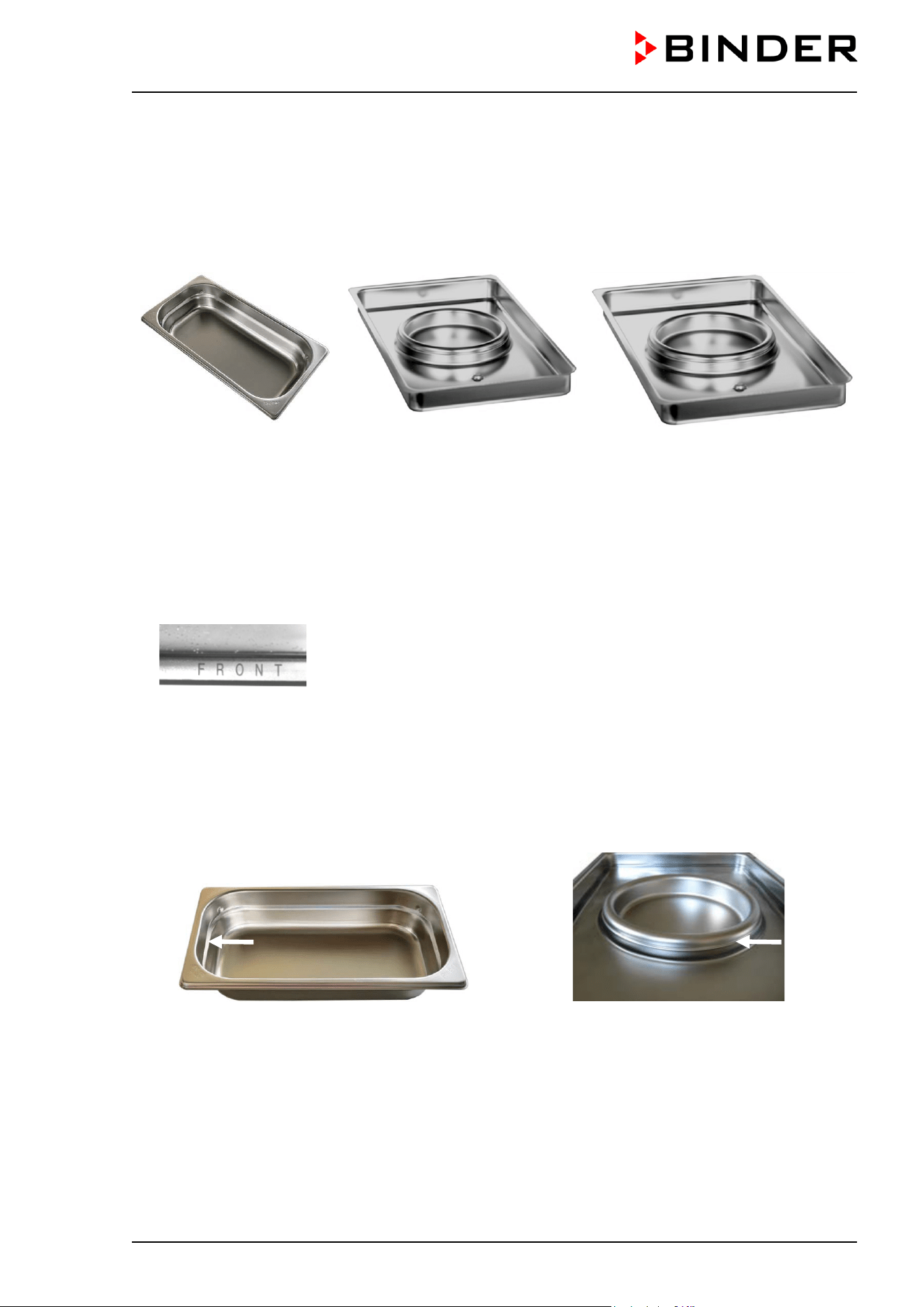
CB / CB-UL, CBF / CBF-UL (E7) 07/2022 Page 34/199
4.2 Permadry™ water pan
The Permadry™ system developed by BINDER is an effective and easy to handle system that ensures
high humidity inside the chamber without any condensation forming on the inner surfaces. The Permadry™
water pan consists of two pans in which the outer one is heated and the inner one cooled. With the slight
difference of temperature caused by that cooling, the central pan is the specific point for condensation of
the surplus humidity. Therefore, all other inner surfaces remain dry.
Incubator size 56 Incubator size 170 Incubator size 260
Figure 10: Permadry™ water pan
• Incubators size 56: Put the water pan in lengthwise direction on the bottom of the inner chamber between
the notches in the chamber bottom. Incubators size 170 / 220: Put the Permadry™ water pan on the
bottom of the inner chamber in a way that both notches lock into place.
• Incubators size 170 / 220: The front side of the Permadry™ water pan for incubators size 170 / 220 is
marked “FRONT”.
Figure 11: Letters “FRONT” indicating the front of the Permadry™ water pan
for incubators size 170 / 220
• Please make sure that the Permadry™ water pan has firm contact to the inner chamber bottom and
rests tightly on it (notches locked into place).
• Incubators size 56: Fill the pan with distilled, sterilized water up to the filling level marking on the inner
edge. Maximum filling quantity: approx. 1.0 liters.
• Incubators size 170 / 220: Fill only the outer pan with distilled, sterilized water up to the filling level
marking on the edge of the inner pan. Maximum filling quantity of the outer basin: incubator size 170:
approx. 1.3 liters, incubator size 260: approx. 2.0 liters.
Figure 12: Incubators size 56,
Filling height line of the pan
Figure 13: Incubators size 170 / 260,
Filling height line of the outer basin
• We recommend cleaning and refilling the pans 2 to 3 times a week. For evacuation, remove the
Permadry™ water pan.
• We recommend using distilled, sterile water to achieve optimum growth results. Any corrosive damage
that may arise following the use of water of different quality or by additives is excluded from the liability
agreement.
• If required, you can add microbiologically inhibiting substances such as copper chips, copper sulfate
or ethylene diamine tetra-vinegar acid (EDTA) in a concentration of 1 to 5 mmol/l.
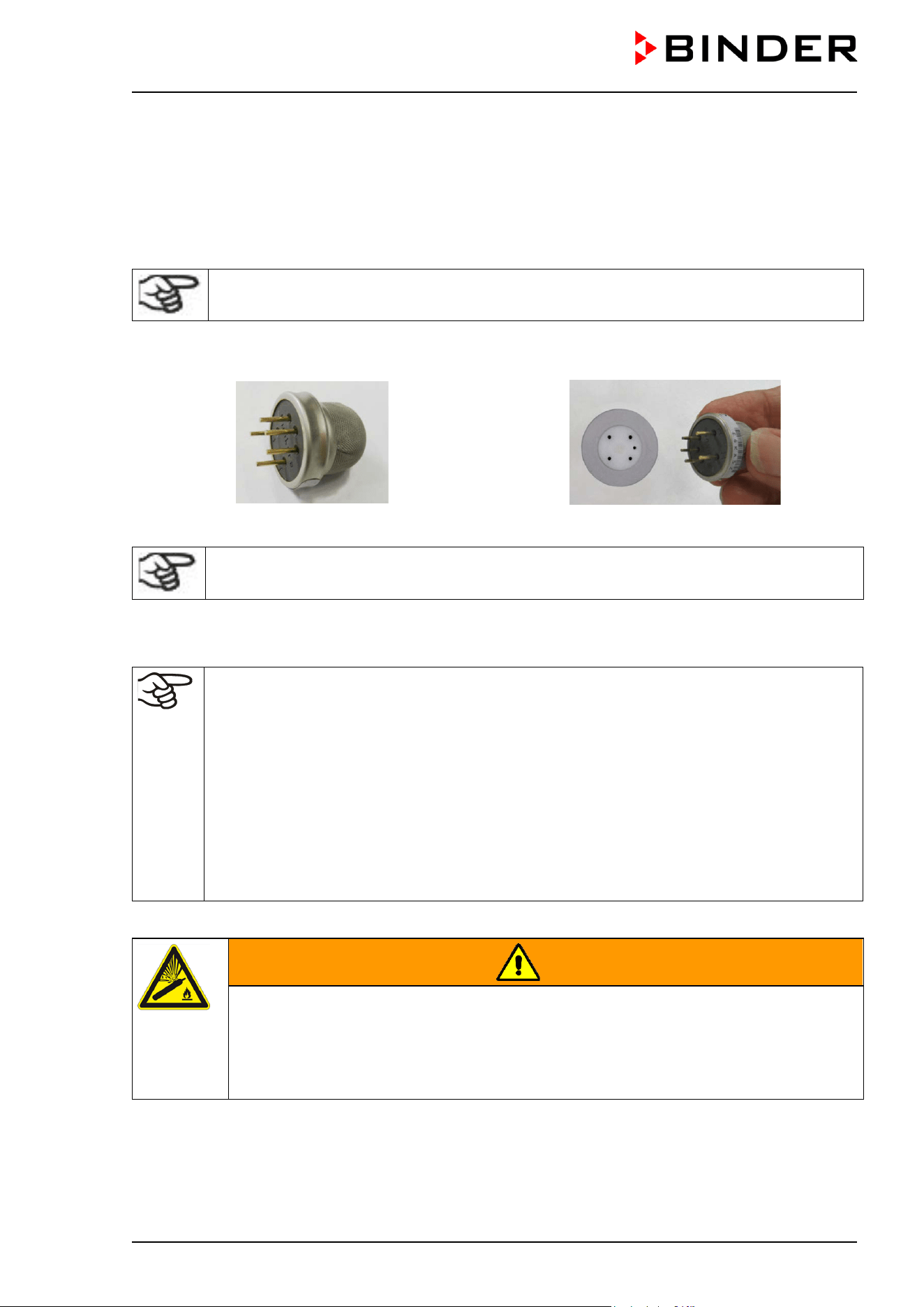
CB / CB-UL, CBF / CBF-UL (E7) 07/2022 Page 35/199
Empty the Permadry™ water pan before moving the chamber. In case of the contents spilling, immediately
shut down the chamber and dry it carefully and completely.
4.3 Connecting the O
2
sensor (chamber with O
2
control)
The O
2
sensor is supplied with the chamber in a separate package.
Connect or remove the O
2
sensor only when the chamber is turned off.
Open the door of the inner chamber and plug the O
2
sensor (F) into the left connection socket located in
the upper part of the rear of the inner chamber. Pay attention to the correct positioning of the pins.
Figure 14: O
2
sensor Figure 15: Connecting the O
2
sensor
The O
2
sensor must be plugged in during a hot-air sterilization.
4.4 Gas connections
General information for safe handling of gas cylinders:
• Store and use gas cylinders only in well ventilated areas.
• Open the gas cylinder valve slowly to avoid pressure surges.
• Secure gas cylinders during storage and use against falling (chaining).
• Transport gas cylinders with a cylinder cart, do not carry, roll, or throw them.
• Always close the valve even with apparently empty cylinders; screw on the cap when not in
use. Return gas cylinders with the valve closed.
• Do not open gas cylinders by force. Mark them when damaged.
• Protect gas cylinders against fire, e.g. do not store together with flammable liquids.
• Observe relevant regulations for dealing with gas cylinders.
Secure the gas cylinders against falling and other mechanical damage.
WARNING
Risk of injury through sudden release of the stored pressure energy when the valve
safety is torn off.
Injuries.
Secure gas cylinders against falling (chaining).
Transport gas cylinders with a cylinder cart.
CB / CB-UL, CBF / CBF-UL (E7) 07/2022 Page 36/199
The valve of the gas cylinder always must be closed before screwing on or unscrewing the gas hose.
WARNING
Risk of injury through sudden release of the stored pressure energy when opening
the cylinder valve of a not connected cylinder.
Injuries.
Close the gas cylinder valve before connecting or removing the gas hose.
After connecting the gas cylinder, check all gas connections for leaks (e.g. with leak spray or
diluted soap solution).
4.4.1 Connection of the CO
2
gas cylinder
Carbon dioxide (CO
2
) in high concentrations is hazardous to health. It is colorless and almost odorless and
therefore practically imperceptible. Vent out any CO
2
gas that may escape via good room ventilation or a
suitable connection to an exhaust system. We recommend installing a CO
2
warning system.
DANGER
Danger of suffocation and poisoning by high concentration of CO
2
(> 4 Vol.-%).
Death by suffocation.
∅ Do NOT set up chambers in non-ventilated recesses.
Ensure technical ventilation measures.
Observe the relevant regulations for handling CO
2
.
Close the CO
2
supply when decommissioning the chamber.
The CO
2
gas necessary for operation must have a technical grade of 99.5 %.
The gas connections must be established by qualified personnel who are trained in handling
the respective gases and familiar with the required safety measures.
The following steps are required:
Ensuring the correct CO
2
output pressure
A gas supply pressure above 2.5 bar / 36 psi will result in chamber damage.
Use a pressure reducer and make sure to avoid any excessive outlet pressure when connecting the gas
hose to the chamber.
The real outlet pressure of gas cylinders, sets of gas cylinders or central gas supplies am on the second
manometer must not exceed 2.5 bar / 36 psi.
CB / CB-UL, CBF / CBF-UL (E7) 07/2022 Page 37/199
NOTICE
Danger of damage by excessive outlet pressure > 2.5 bar / 36 psi.
Damage to the chamber.
∅ The outlet pressure must NOT exceed the indicated value of 2.5 bar / 36 psi.
Before connecting, check the outlet pressure on the pressure reducer of the cylinder.
Adjust the outlet pressure to 2.0 bar / 29 psi above the ambient pressure.
Observe the correct outlet pressure also when replacing the gas cylinders.
Establishing the connection to the chamber
Connect the supplied gas hose (internal diameter 6 mm / 0.24 inches) to the pressure reducer of the
gas cylinders or central gas supply and secure the connection with the supplied hose clamp.
Connect the pre-assembled hose nozzle of the gas hose to the quick acting closure socket (10) DN 6
on the chamber rear, as described in chap. 4.4.4.
Leak test
After connecting the gas cylinder, check all gas connections for leaks (e.g. with leak spray or diluted
soap solution).
The recovery times of the gas concentrations inside the chamber after opening the door are
indicated in the technical data (chap. 24.4) and refer to a connection pressure of 2.0 bar / 29
psi. Decreasing supply pressure will result in longer recovery times.
Conversion table for gas inlet pressures, bar – psi, see chap. 24.8.
4.4.2 Connection of the O
2
gas cylinder (chamber with O
2
control with optional
alternative control range 10 up to 95 vol.-% O
2
)
Note: Do not connect the O
2
cylinder or disconnect the gas supply (by pulling off the gas
hose) when operating at setpoints below 19 vol.-% O
2
.
Oxygen (O
2
) is colorless and almost odorless and therefore practically imperceptible. It promotes burns,
which can proceed explosively. There is a fire hazard for flammable oxygenated materials, e.g. clothes and
hair. O
2
is heavier than air and may accumulate in low-lying areas.
DANGER
Danger of fire and explosion through contact of combustible materials with O
2
with high concentration of O
2
(> 21 % O
2
).
Serious injury or death from burns and / or explosion pressure.
∅ Do NOT set up chambers in non-ventilated recesses.
Ensure technical ventilation measures.
Observe the relevant regulations for handling O
2
.
Close the O
2
supply when decommissioning the chamber.
The O
2
gas necessary for operation must have a technical grade of 99.5 %.
The gas connections must be established by qualified personnel who are trained in handling
the respective gases and familiar with the required safety measures.
CB / CB-UL, CBF / CBF-UL (E7) 07/2022 Page 38/199
The following steps are required:
Ensuring the correct O
2
output pressure
A gas supply pressure above 2.5 bar / 36 psi will result in chamber damage.
Use a pressure reducer and make sure to avoid any excessive outlet pressure when connecting the gas
hose to the chamber.
The real outlet pressure of gas cylinders, sets of gas cylinders or central gas supplies am on the second
manometer must not exceed 2.5 bar / 36 psi.
NOTICE
Danger of damage by excessive outlet pressure > 2.5 bar / 36 psi.
Damage to the chamber.
∅ The outlet pressure must NOT exceed the indicated value of 2.5 bar / 36 psi.
Before connecting, check the outlet pressure on the pressure reducer of the cylinder.
Adjust the pressure to 2.0 bar / 29 psi above the ambient pressure.
Observe the correct outlet pressure also when replacing the gas cylinders.
Establishing the connection to the chamber
Connect the supplied gas hose (internal diameter 6 mm / 0.24 inches) to the pressure reducer of the
gas cylinders or central gas supply and secure the connection with the supplied hose clamp.
Connect the pre-assembled hose nozzle of the gas hose to the quick acting closure socket (11) DN 6
on the chamber rear, as described in chap. 4.4.4.
Leak test
After connecting the gas cylinder, check all gas connections for leaks (e.g. with leak spray or diluted
soap solution).
The recovery times of the gas concentrations inside the chamber after opening the door are
indicated in the technical data (chap. 24.4) and refer to a connection pressure of 2.0 bar / 29
psi. Decreasing supply pressure will result in longer recovery times.
Conversion table for gas inlet pressures, bar – psi, see chap. 24.8.
4.4.3 Connection of the N
2
gas cylinder (chamber with O
2
control)
Nitrogen (N
2
) in high concentrations is hazardous to health. It is colorless and almost odorless and therefore
practically imperceptible. Any N
2
gas that may escape must be safely led out via good room ventilation or
a suitable connection to an exhaust system.
DANGER
Risk of suffocation through high concentration of N
2
.
Death by suffocation.
∅ Do NOT set up chambers in non-ventilated recesses.
Ensure technical ventilation measures.
Observe the relevant regulations for handling N
2
.
Close the N
2
supply when decommissioning the chamber.
The N
2
gas necessary for operation must have a technical grade of 99.5 %.
CB / CB-UL, CBF / CBF-UL (E7) 07/2022 Page 39/199
The gas connections must be established by qualified personnel who are trained in handling
the respective gases and familiar with the required safety measures.
The following steps are required:
Ensuring the correct N
2
output pressure
A gas supply pressure above 2.5 bar / 36 psi will result in chamber damage.
Use a pressure reducer and make sure to avoid any excessive outlet pressure when connecting the gas
hose to the chamber.
The real outlet pressure of gas cylinders, sets of gas cylinders or central gas supplies am on the second
manometer must not exceed 2.5 bar / 36 psi.
NOTICE
Danger of damage by excessive outlet pressure > 2.5 bar / 36 psi.
Damage to the chamber.
∅ The outlet pressure must NOT exceed the indicated value of 2.5 bar / 36 psi.
Before connecting, check the outlet pressure on the pressure reducer of the cylinder.
Adjust the pressure to 2.0 bar / 29 psi above the ambient pressure.
Observe the correct outlet pressure also when replacing the gas cylinders.
Establishing the connection to the chamber
Connect the supplied gas hose (internal diameter 6 mm / 0.24 inches) to the pressure reducer of the
gas cylinders or central gas supply and secure the connection with the supplied hose clamp.
Connect the pre-assembled hose nozzle of the gas hose to the quick acting closure socket (9) DN 6 on
the chamber rear, as described in chap. 4.4.4.
Leak test
After connecting the gas cylinder, check all gas connections for leaks (e.g. with leak spray or diluted
soap solution).
The recovery times of the gas concentrations inside the chamber after opening the door are
indicated in the technical data (chap. 24.4) and refer to a connection pressure of 2.0 bar / 29
psi. Decreasing supply pressure will result in longer recovery times.
Conversion table for gas inlet pressures, bar – psi, see chap. 24.8.
4.4.4 Connecting the gas hose to the chamber rear (for CO
2
, O
2
, N
2
)
The procedure of connecting the gas hose to the chamber rear is the same for any gas connection. All
quick acting closure sockets (CO
2
, N
2
with O
2
control, and O
2
with O
2
control and optional alternative control
range 10 up to 95 vol.-% O
2
) are degreased and supplied with a FKM gasket.
Note for chambers with O
2
control: The quick acting closure socket and the hose nozzle for the O
2
connection must be degreased.
DANGER
Fire and explosion hazard through contact of fat with O
2
.
Serious injury or death from burns and / or explosion pressure.
∅ All connection parts for the O
2
connection must be degreased.
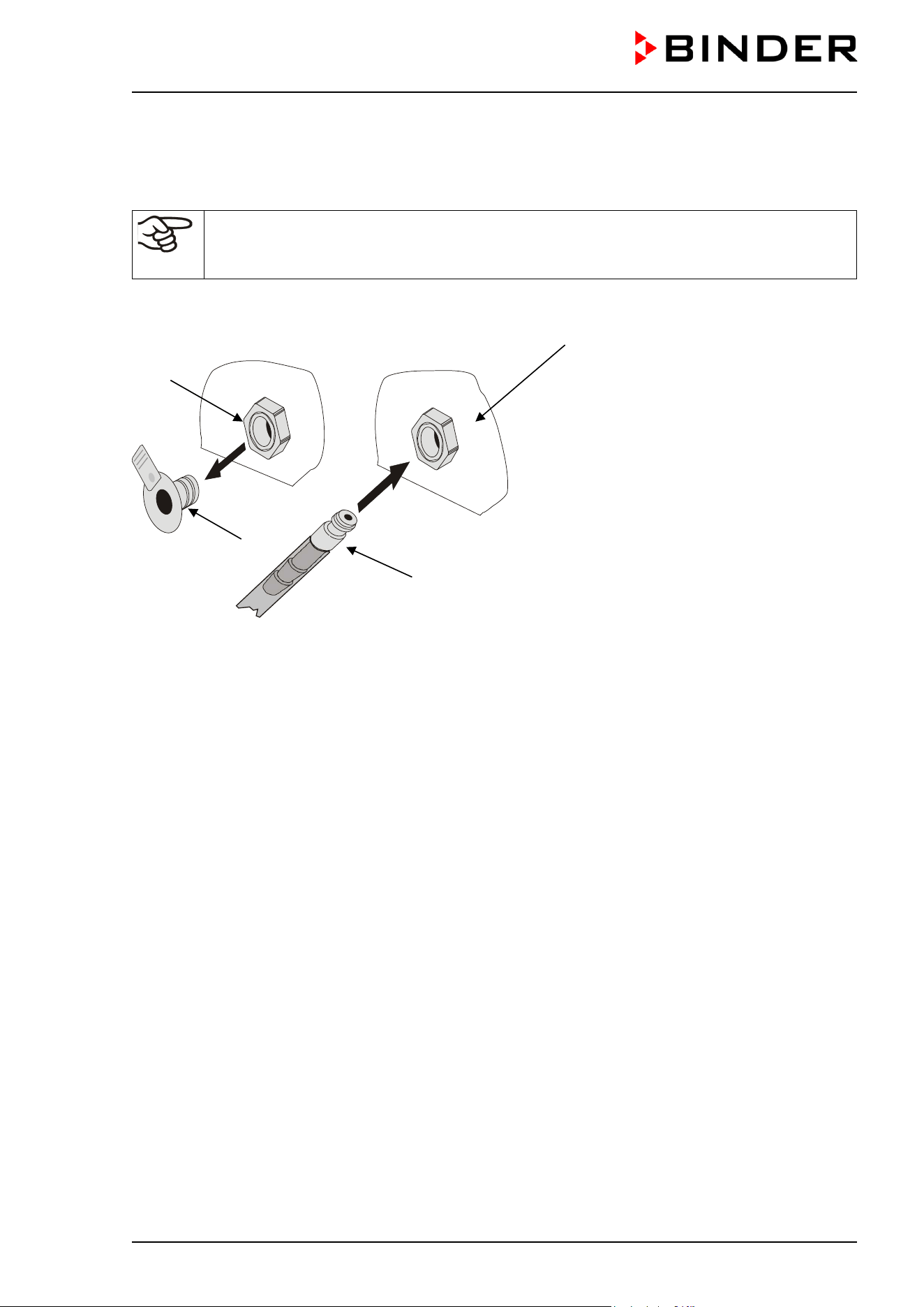
CB / CB-UL, CBF / CBF-UL (E7) 07/2022 Page 40/199
The gas hose, which will be used to establish the connection to a gas cylinder, is already attached to the
hose nozzle and secured by a hose clamp. Plug the hose nozzle into the corresponding quick acting closure
socket (a) located at the rear of the chamber. This quick acting closure socket is closed by a rubber cover
(b).
Only use the supplied hose nozzle to connect to the quick acting closure socket.
Otherwise, the quick acting closure socket may leak, and/or it may become impossible to
connect the original hose nozzle. In this case, please contact BINDER Service.
Remove the rubber cover (b) by pulling it off.
Chamber rear
Figure 16: Connecting the hose lead to the gas cylinder
Now fit the hose nozzle (c) in the quick acting closure socket. To remove the connection, pull the hose
nozzle off the quick acting closure socket.
(a)
(c)
(b)
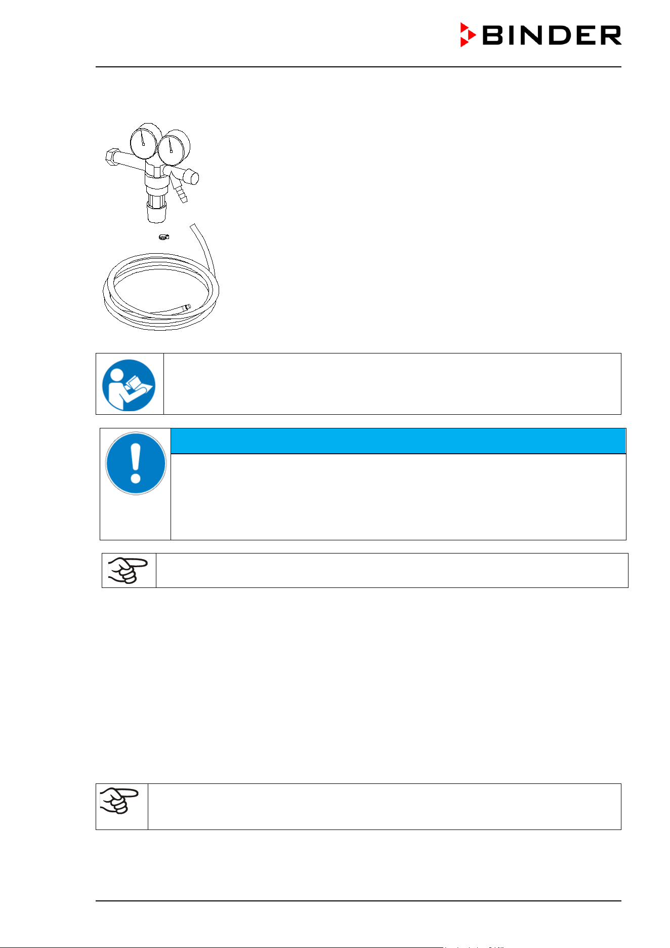
CB / CB-UL, CBF / CBF-UL (E7) 07/2022 Page 41/199
4.4.5 Gas cylinder connection kits (option)
Gas cylinder connection kits are available for CO
2
(Art. No. 8012-0014), O
2
(Art. No. 8012-0015) and N
2
(Art. No. 8012-0016).
The connection kit includes the following parts for connecting a gas cylinder
to the CO
2
incubator:
• Pressure reducer with manometers for cylinder pressure (high pressure
gauge) and outlet pressure (low pressure gauge)
• 5 m pressure hose with pre-
assembled hose nozzle for quick acting
closure socket
• 1 hose clamp to connect the gas hose to the pressure reducer
Figure 17: Gas cylinder connection kit
Instructions 7001-0249 included with the connection kit describe connecting and setting
the gas cylinder connection kit.
NOTICE
Danger of damage by excessive outlet pressure > 2.5 bar / 36 psi.
Damage to the chamber.
∅ The outlet pressure must NOT exceed the indicated value of 2.5 bar / 36 psi.
Before connecting, check the outlet pressure on the pressure reducer of the cylinder.
Adjust the outlet pressure to 2.0 bar / 29 psi above the ambient pressure.
The gas connections must be established by qualified personnel who are trained in handling
the respective gases and familiar with the required safety measures.
4.5 CBF / CBF-UL: Water supply and dehumidification
4.5.1 General remarks on water supply
4.5.1.1 Water supply
Freshwater is supplied by manually filling a freshwater bag (tubular bag set, standard, can be reordered)
or a freshwater can (optional water container set). It is also possible to connect prefilled water bottles
(optional humidification water set). It is not possible to connect the chamber directly to a water pipe.
The freshwater bag has a volume of 0.9 liters / 0.32 cu.ft. and is placed behind the chamber door in a
recess.
To guarantee humidification during 24 hours even at high humidity set-points and / or
frequent door openings, we recommend checking the freshwater bag daily at the end of the
day.
When the freshwater can is empty, the message “Freshwater supply” will be displayed on the controller,
the buzzer sounds, and the humidification module turns off. After acknowledging the alarm, the
humidification module tries to fill up and start operating.
CB / CB-UL, CBF / CBF-UL (E7) 07/2022 Page 42/199
Water consumption at 37 °C / 98.6 °F and 93 % r.h.:
• Without opening the door: very low.
• When opening the door 10 times a day: approx. 70 ml per day.
4.5.1.2 Dehumidification
To reduce the humidity, ambient air is sucked in through a gas fine filter (sterile filter). As a result, the air in
the interior is diluted with the air from outside. The air tube for inlet of the ambient air is located in the upper
right corner in the recess for the freshwater bag. We recommend replacing the sterile filter on this tube
about once a month. To replace the sterile filter, see chap. 22.2.3.
4.5.1.3 Types of suitable water quality
• Deionized water from a water treatment installation already existing at the customer's site. Conductivity
from 1 µS /cm up to a maximum of 20 µS/cm. (Water, which is in equilibrium with the CO
2
in the air, and
has a conductivity below 1 µS/cm (ultrapure water), may cause acid corrosion due to its low pH).
• Tap water that has been treated by the optional water treatment system BINDER Pure Aqua Service
(disposable system). A reusable measuring equipment to assess the water quality is included (chap.
4.5.1.4).
BINDER GmbH is NOT responsible for the water quality at the user’s site.
Any problems and malfunctions that might arise following use of water of deviating quality is
excluded from liability by BINDER GmbH.
The warranty becomes void in the event of use of water of deviating quality.
NOTICE
Danger of calcification of the humidifying system.
Damage to the chamber.
Operate the chamber with deionized (demineralized) water only.
Water intake temperature NOT below +5 °C / 41 °F and not exceeding 40 °C / 104 °F.
4.5.1.4 BINDER Pure Aqua Service (option)
The optional BINDER water treatment system (disposable system) is available to treat tap water. The
lifetime depends on water quality and the amount of treated water used. The measuring equipment to
assess the water quality is reusable.
For detailed information on operating the water treatment system BINDER Pure Aqua
Service and its function, please refer to the operating manual supplied with BINDER Pure
Aqua Service.
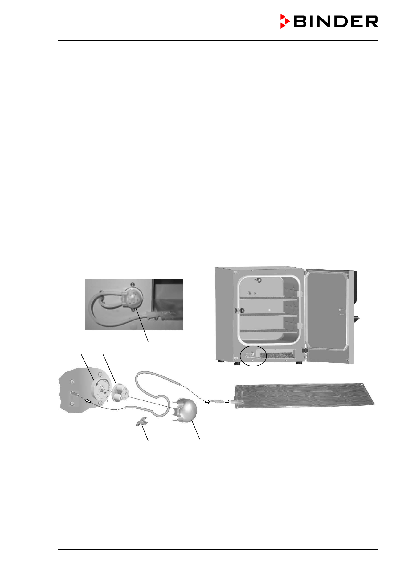
CB / CB-UL, CBF / CBF-UL (E7) 07/2022 Page 43/199
4.5.2 Water supply via freshwater bag (standard)
4.5.2.1 Scope of delivery
The optional tubular bag set includes all necessary connecting parts:
• Set art. no. 8009-1083 with 3 freshwater bags (included in scope of delivery)
• Set art. no. 8009-1058 with 12 freshwater bags (option, annual demand)
Each bag set includes:
• 3 resp. 12 (optional kit) freshwater bags (art.no. 6002-0626)
• 3 two-piece tube connectors with 3-5mm nozzles (art.no. 6009-0322)
• 3 two-piece tube connectors with 5-7mm nozzles (art.no. 6009-0323)
• 3 resp. 12 (optional kit) gas fine filters (sterile filter) (art.no. 6014-0012)
• 6 m silicone tube (DN 3mm) (art.no. 6008-0267)
• 1m filling tube (DN 10 mm) (art.no. 6008-0268)
• Instructions (art.no. 7001-0385)
4.5.2.2 Installation and connection of the freshwater bag
Figure 18: Installation of the water supply via freshwater bag
(12) Pump head
(12a) Pump head cover
(12b) Tube retainer
(12c) Rotor
(13) Pump connector
(13) (12c) (12)
(12b) (12a)
①
②
③
④
⑤
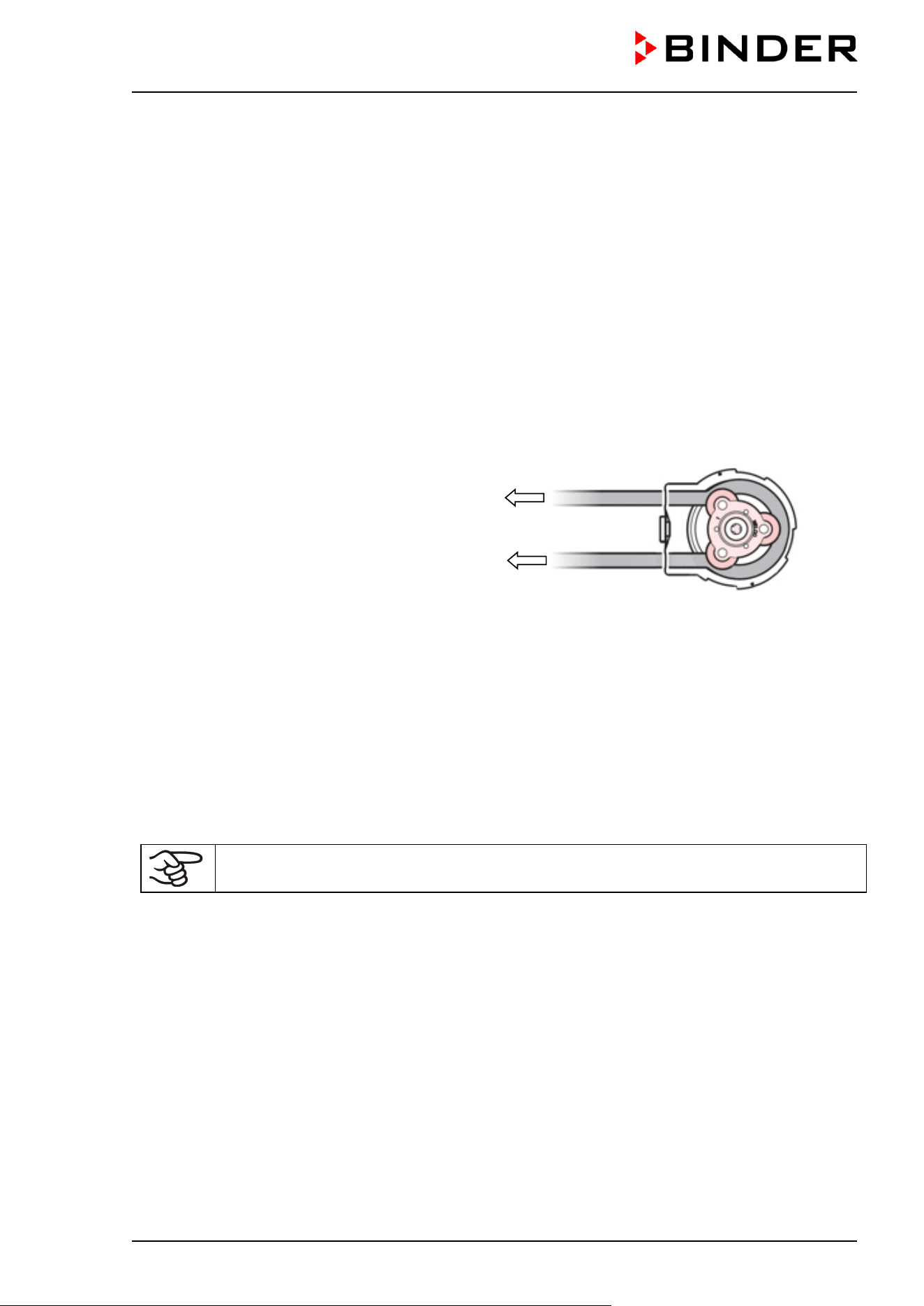
CB / CB-UL, CBF / CBF-UL (E7) 07/2022 Page 44/199
Please proceed in the following order:
• Fill the freshwater bag. Observe water quality and temperature (chap. 4.5.1.3).
• Attach a tube connector part with a 5-7 mm nozzle to the freshwater bag ①
• Attach a tube connector part with a 3-5 mm nozzle to the silicone tube ②
• Connect both tube connector parts
• Turn the pump head (12) counterclockwise until it stops and remove it from the pump connector (13).
• Pull up the tongue of the tube retainer (12b) up to “Click” and remove it. Take the rotor (12c) out of the
pump head cover (12a). ③
• Lead the silicone tube along the rotor. Insert the rotor with the tube into the pump head cover. Keep the
hose tight and do not pinch it. ④
The end of the tube for connecting to the incubator should be about 6 cm long. With a total length of the
silicone tube of 32 cm, the tube end for connecting the freshwater bag has a length of approx. 18 cm
• Press the tube retainer (12b) into the pump head cover until it snaps into place
to freshwater bag
to incubator connection
Figure 19: Inserting the silicone tube into the pump head ④
• Insert the pump head (12) into the pump connector (13) and turn it clockwise until it snaps into place.
• Attach the silicone tube to the incubator connection ⑤
• Place the freshwater bag with the opening to the left in the recess behind the chamber door.
4.5.2.3 Refilling the already installed freshwater bag
For easier handling, you can temporarily release the pump head from the pump connector
on the incubator.
Standard procedure
• Remove the connection between the both parts of the tube connector①.
• Depending on the diameter of the object used for filling (hose, spray bottle ...), you may remove the
connection between the hose connector part and the freshwater bag ①.
• Fill the freshwater bag. Observe water quality and temperature (chap. 4.5.1.3).
• If it has been removed, put the tube connector part with a 5-7 mm nozzle back on the freshwater bag
①
• Reassemble the two parts of the tube connector ①.
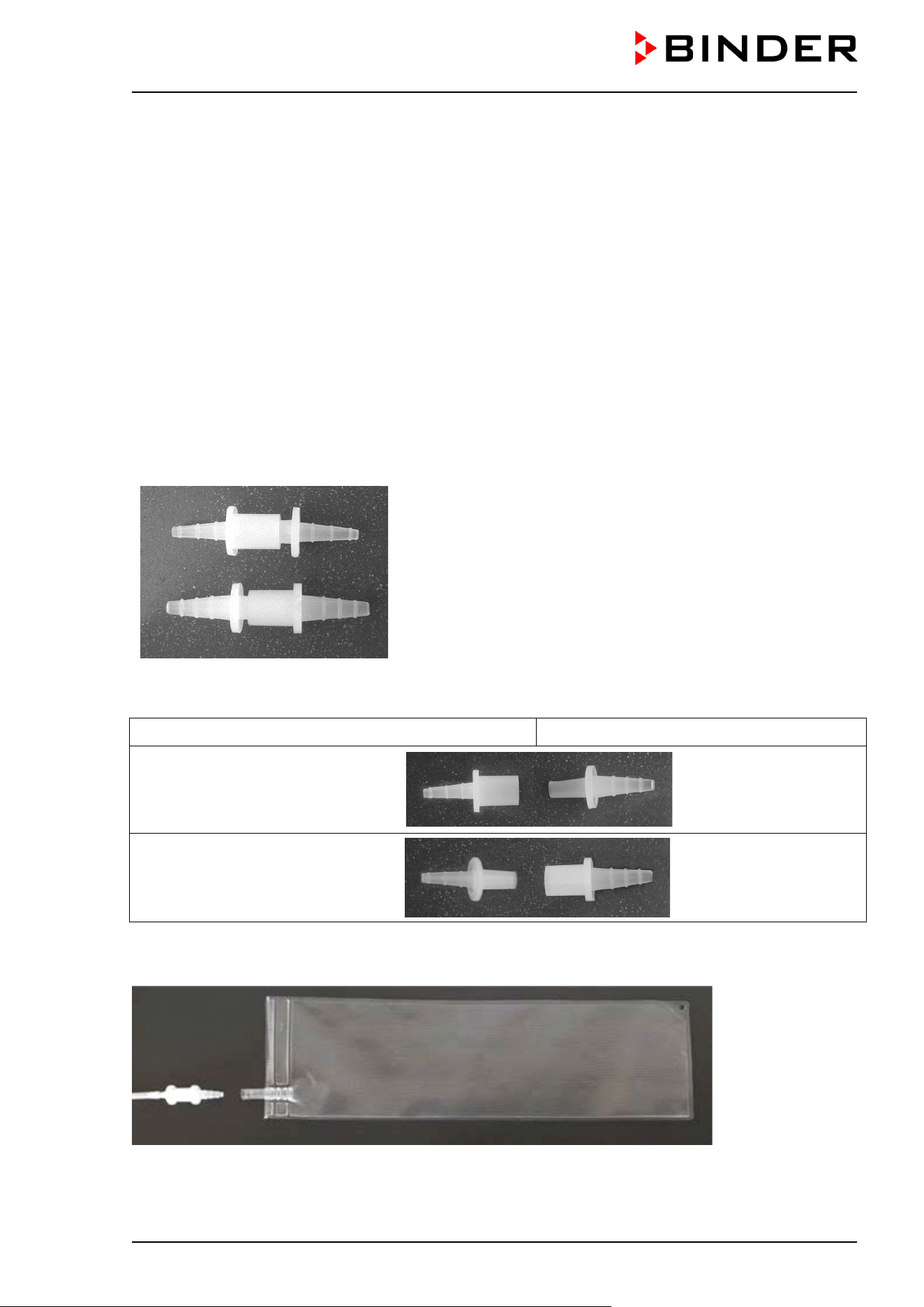
CB / CB-UL, CBF / CBF-UL (E7) 07/2022 Page 45/199
Procedure with optional filling hose
A bag set (Art.no. 8009-1058) incl. accessories (annual demand) is optionally available (chap. 4.5.2). For
easier filling, the set contains a filling tube (DN 10 mm) of 1 m length with a fitting tube connector.
• Remove the connection between both parts of the tube connector ①
• Attach the filling tube to the tube connector part which is still on the freshwater bag
• Fill the freshwater bag. Observe water quality and temperature (chap. 4.5.1.3).
• Remove the filling tube from the tube connector on the freshwater bag
• Reassemble the two parts of the tube connector ①.
4.5.2.4 Replacing the tube connectors for freshwater supply
3 two-piece tube connectors with 3-5mm nozzles und 3 two-piece tube connectors with 5-7mm nozzles are
included with the optional bag set.
State of delivery:
Two-piece tube connector with 3-5mm nozzles
Two-piece tube connector with 5-7mm nozzles
For connection to the silicone tube and the freshwater bag, the hose connectors must be combined
accordingly:
To silicone tube: 3-5 mm nozzle To freshwater bag: 5-7 mm nozzle
Combination 1:
Opening
NW 7 mm
Opening
NW 4 mm
Combination 2:
(recommended)
Opening
NW 4 mm
Opening
NW 7 mm
Connecting the freshwater bag
Put the filled freshwater bag on the nozzle of the hose connector.
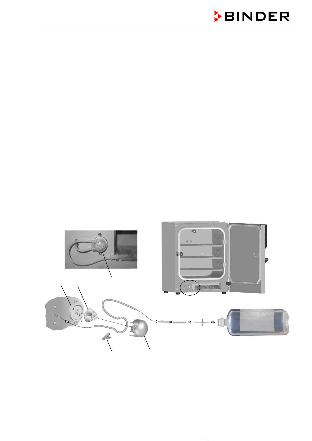
CB / CB-UL, CBF / CBF-UL (E7) 07/2022 Page 46/199
4.5.3 Water supply via prefilled water bottle (optional humidification water set)
By using the humidification water set you will achieve unsurpassed contamination safety of your samples
in the BINDER CO
2
incubator CBF / CBF-UL.
4.5.3.1 Scope of delivery
The optional humidification water set includes all necessary connecting parts:
• Art.no. 8009-1104 Set with 10 prefilled one-liter bottles (annual demand)
The humidification water set includes:
• 10 one-liter bottles, prefilled with sterile, deionized water (art.no. 1007-0314)
• 3 spike connectors (transfer sets) for sterile liquids (art.no. 6007-0131)
• 3 two-piece tube connectors with 3-5mm nozzles (art.no. 6009-0322)
• 2 m silicone tube (DN 3mm) (art.no. 6008-0267)
• 3 gas fine filters (sterile filter) (art.no. 6014-0012)
• 20 cm silicone tube (DN 6 mm) (art.no. 6008-0009)
• Instructions (art.no. 7001-0385)
4.5.3.2 Installation, connection and change of the prefilled water bottle
The optional humidification water set includes all necessary connecting parts.
Figure 20: Installation of the water supply via prefilled water bottle
(12) Pump head
(12a) Pump head cover
(12b) Tube retainer
(12c) Rotor
(13) Pump connector
(13) (12c) (12)
(12b) (12a)
①
②
③
④ ⑤ ⑥ ⑦
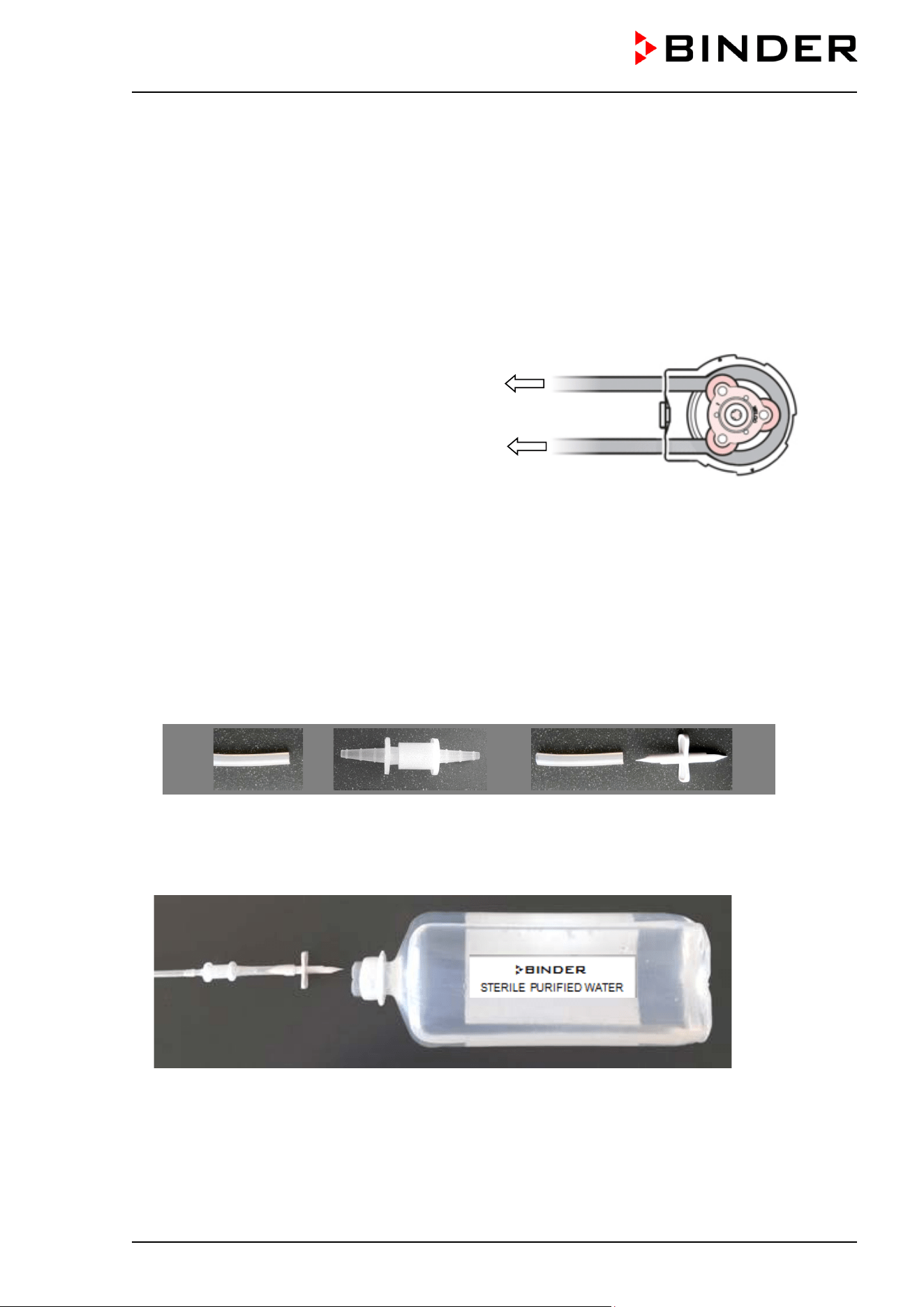
CB / CB-UL, CBF / CBF-UL (E7) 07/2022 Page 47/199
Please proceed in the following order:
• Turn the pump head (12) counterclockwise until it stops and remove it from the pump connector (13).
• Pull up the tongue of the tube retainer (12b) up to “Click” and remove it. Take the rotor (12c) out of the
pump head cover (12a). ①
• Lead the silicone tube along the rotor. Insert the rotor with the tube into the pump head cover. Keep the
hose tight and do not pinch it.②
The end of the tube for connecting to the incubator should be about 6 cm long. With a total length of the
silicone tube of 32 cm, the tube end for connecting the water bottle has a length of approx. 18 cm
• Press the tube retainer (12b) into the pump head cover until it snaps into place.
to water bottle
to incubator connection
Figure 21: Inserting the silicone tube into the pump head②
• Insert the pump head (12) into the pump connector (13) and turn it clockwise until it snaps into place.
• Attach the silicone tube to the incubator connection. ③
• Plug the part of the tube connector with 3-5mm nozzle in the silicon tube. ④
• Connect the free nozzle of the tube connector with a part of the silicon tube DN 6 mm ⑤
• Remove the protective cap of the spike connector (transfer set) and connect the nozzle of the tube
connector with the spike connectors using a part of the DN 6 mm silicone tube. ⑥
Silicone tube of the
water system
Two-piece tube
connector
Silicone tube
DN 6 mm
Spike connector
(transfer set)
• Then remove the second protective cap of the spike connector and insert the piercing pin into the water
bottle through the silicone seal. ⑦
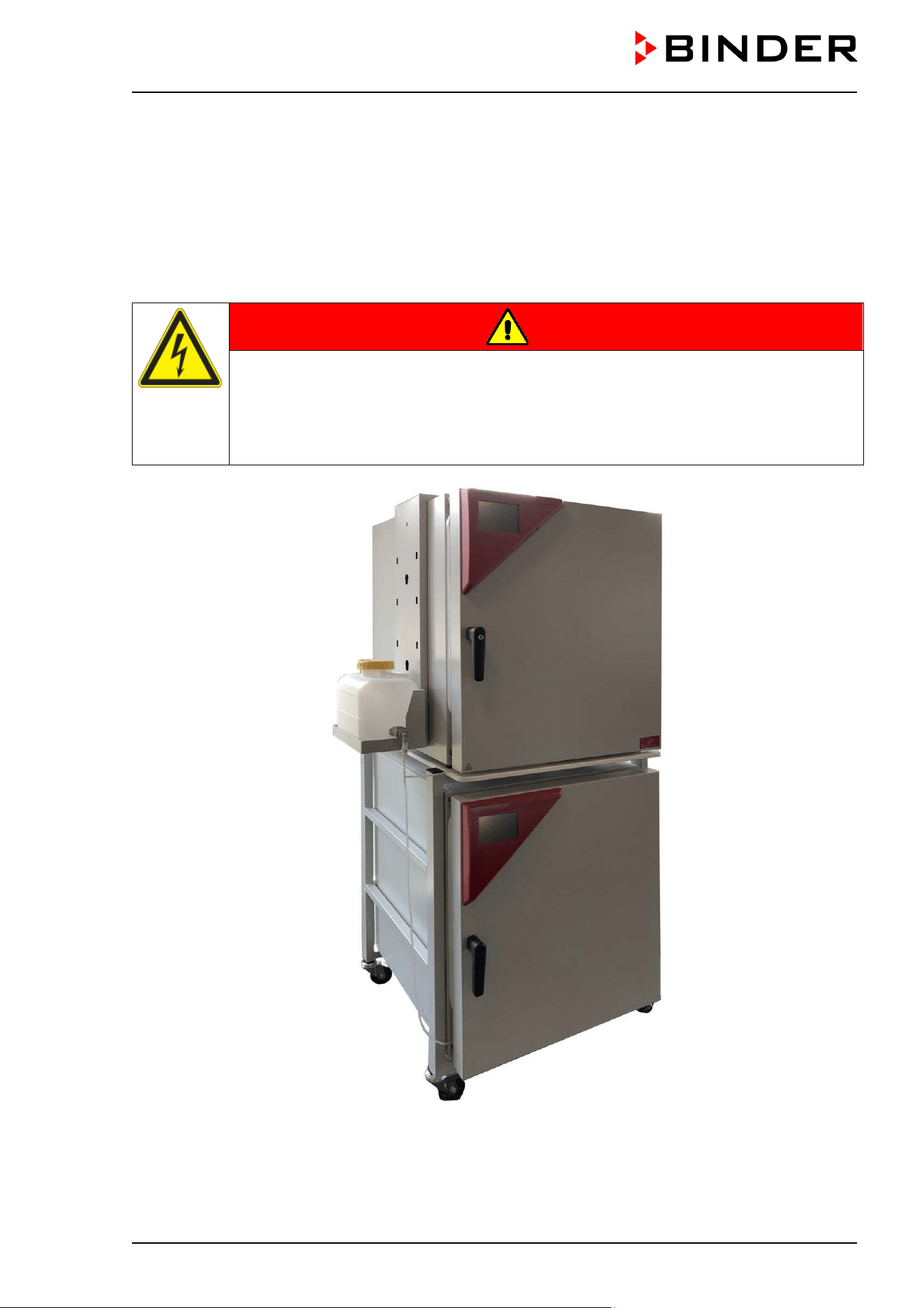
CB / CB-UL, CBF / CBF-UL (E7) 07/2022 Page 48/199
4.5.4 Water supply via freshwater can (optional water container set)
The fresh water can, which is placed in an included magnetic can holder on the left chamber side, serves
to supply one or several chambers with freshwater for humidification.
Since the pump is self-priming, it is not required that the water outlet of the can should be placed higher
than the pump, so you can position the water can freely in height.
The freshwater can outlet must NOT be placed on or above the rear panel of the chamber or on the right
chamber side.
DANGER
Electrical hazard by water entering the chamber via the rear panel.
Deadly electric shock.
The magnetic support adjustable in height (option) may only be attached on the left side
of the chamber.
∅ Do NOT place the freshwater can tap on or above the rear panel of the chamber
Figure 22: Two CBF / CBF-UL incubators with installed water supply via freshwater can (option)
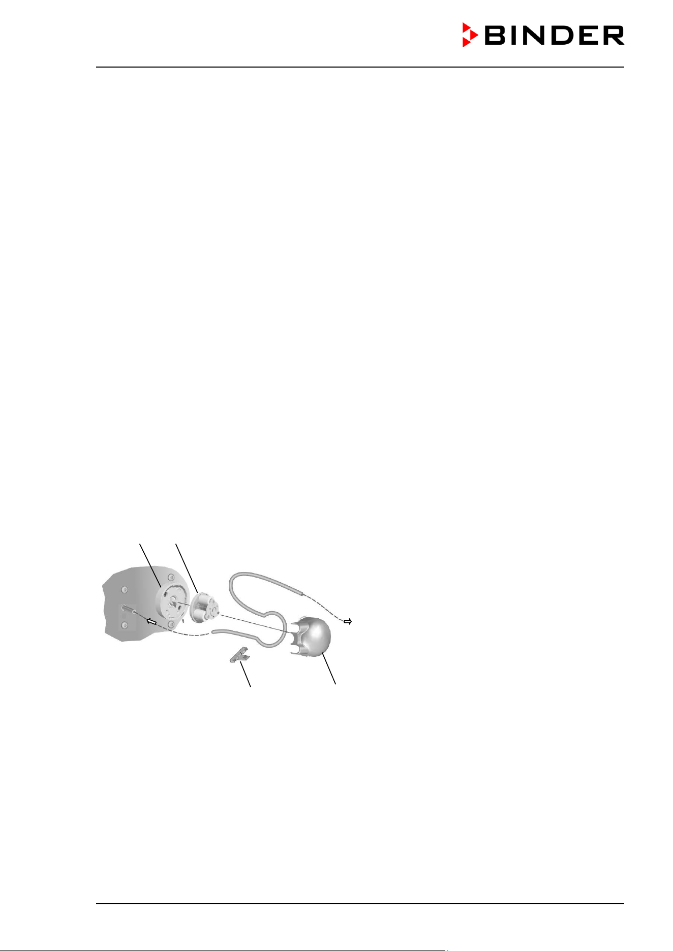
CB / CB-UL, CBF / CBF-UL (E7) 07/2022 Page 49/199
4.5.4.1 Scope of delivery
The optional water container set includes all necessary connecting parts:
• Art. no. 8009-1128 Set with freshwater can, magnetic support and connecting parts
The water container set includes:
• Magnetic can holder adjustable in height, consisting of magnetic holder (art.no. 8022-0009) and water
can support (art.no. 4021-0724)
• Water can, 10 l (art.no. 6011-0192)
• Hose coupling with aqua stop (art.no. 6002-0637)
• Angular coupling plug with aqua stop (art.no. 6002-0638)
• 12 gas fine filters (sterile filter) (art.no. 6014-0012)
• 10 m silicone tube (DN 3mm) (art.no. 6008-0267) to the pump or via T-type tube connectors to further
chambers
• 50 cm silicone tube, d10 x 2 (art.no. 6008-0268)
• Reducing connector (tube connector 4/9 mm) (art.no. 6009-0308)
• 4 wire tension clamps (art.no. 6009-0281) (2 spare parts)
• 3 T-type tube connectors (T-Pieces), 4mm (art.no. 6009-0318)
• Instructions (art.no. 7001-0385)
4.5.4.2 Installation and connection of the freshwater can (optional water container set)
The optional water container set includes all necessary connecting parts.
First, the silicone hose DN 3mm (24) must be connected to the chamber and led through the pump
(12) Pump head
(12a) Pump head cover
(12b) Tube retainer
(12c) Rotor
(13) Pump connector
(24) Silicone tube DN 3mm to water can
Figure 23: Installation of the water supply at the pump
Please proceed in the following order:
• Turn the pump head (12) counterclockwise until it stops and remove it from the pump connector (13).
• Pull up the tongue of the tube retainer (12b) up to “Click” and remove it. Take the rotor (12c) out of the
pump head cover (12a). ①
• Lead the silicone tube along the rotor. Insert the rotor with the tube into the pump head cover. Keep the
hose tight and do not pinch it.②
(13) (12c)
(12b) (12a)
①
②
③
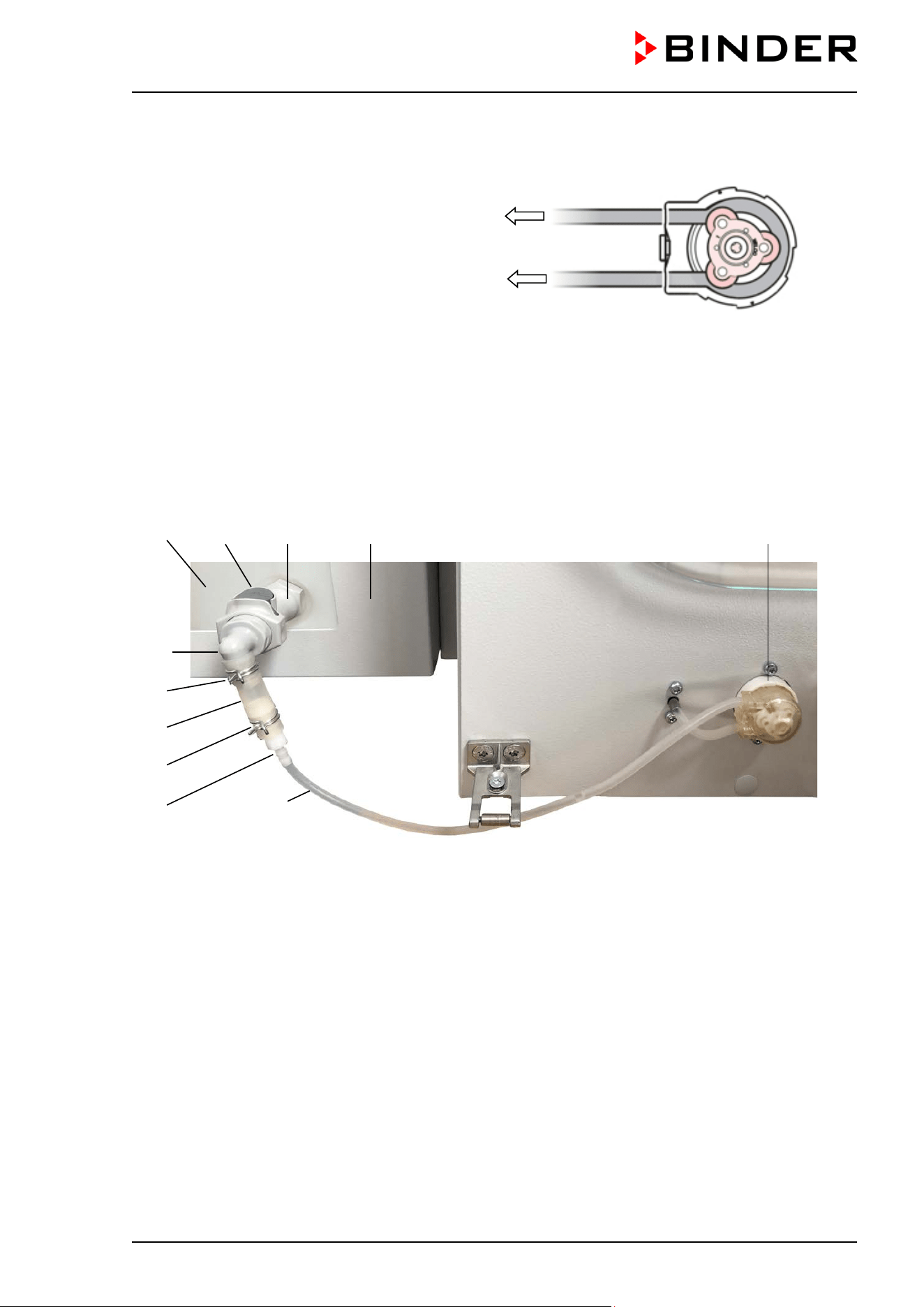
CB / CB-UL, CBF / CBF-UL (E7) 07/2022 Page 50/199
The end of the tube for connecting to the incubator should be about 6 cm long.
• Press the tube retainer (12b) into the pump head cover until it snaps into place.
to water can
to incubator connection
Figure 24: Inserting the silicone tube into the pump head ②
• Insert the pump head (12) into the pump connector (13) and turn it clockwise until it snaps into place.
• Attach the silicone tube to the incubator connection. ③
Now you can attach the freshwater can at the chamber and establish the hose connection to the freshwater
can.
Figure 25: Installation of the water supply via freshwater can, example with single chamber
(17) Freshwater can
(18) Magnetic can holder (water can support)
(19) Hose coupling with aqua stop
(19a) Removal button
(20) Angular coupling plug with aqua stop
(21) Silicone tube d 10
(22) Reducing connector
(23) Wire tension clamp
(24) Silicone tube DN 3mm to the pump (or via T-
type tube connector (T-piece)
to another
chamber)
(12) Pump
(17) (19a) (19) (18) (12)
(20)
(23)
(21)
(23)
(22) (24)

CB / CB-UL, CBF / CBF-UL (E7) 07/2022 Page 51/199
Please proceed in the following order:
• Assemble the magnetic can holder (18): Attach the water can support to the holder
• Attach the magnetic can holder (18) to the left chamber side
• Insert the freshwater can (17) from above into the water can support
• Screw the hose coupling with aqua stop (19) on the water can outlet
• Insert the angular coupling plug (20) into the hose coupling. The gray removal button (19a) on the hose
coupling snaps into place.
• Attach a 5 cm piece of the silicone tube d10 (21) to the angular coupling plug.
• Insert the reducing connector (22) into the silicone tube (21)
• Secure both sides of the silicone tube (21) each with a wire tension clamp (23)
Water supply for a single chamber:
• Plug the silicone tube DN 3mm (24) coming from the pump (12) on the reducing connector (22)
Water supply for several chambers:
You can branch off the water supply via T-pieces for additional chambers.
• Divide the silicone tube DN 3mm (24) into pieces of a suitable length. Take into account the height of
the magnetic can holder
• Put a piece of the silicone tube DN 3mm (24) on the reducing connector (22) and connect a T-piece to
the free end
• If there are more than two chambers, you can connect another T-piece using a piece of the silicone tube
DN 3mm (24)
• For each chamber, plug the silicone tube DN 3mm (24) coming from the pump (12) onto the free outlet
of the T-piece
Now you can fill the freshwater can. Observe water quality and temperature. Do not firmly close the lid of
the freshwater can to allow air to enter the freshwater can. As a result, obstruction of the water supply due
to negative pressure inside the can is avoided.
4.5.4.3 Refilling the freshwater can
For refilling later, you can remove the freshwater can from the water can support. Press the grey removal
button on the hose coupling, then the angle coupling plug can be removed. A small amount of water can
escape (filling amount of the angular coupling plug). The water can outlet remains closed due to the aqua
stop.
Alternatively, you can remove the lid and fill the can on site with a suitable aid (water hose, watering can).
When filling on site, the existing hose connection can remain on the freshwater can.
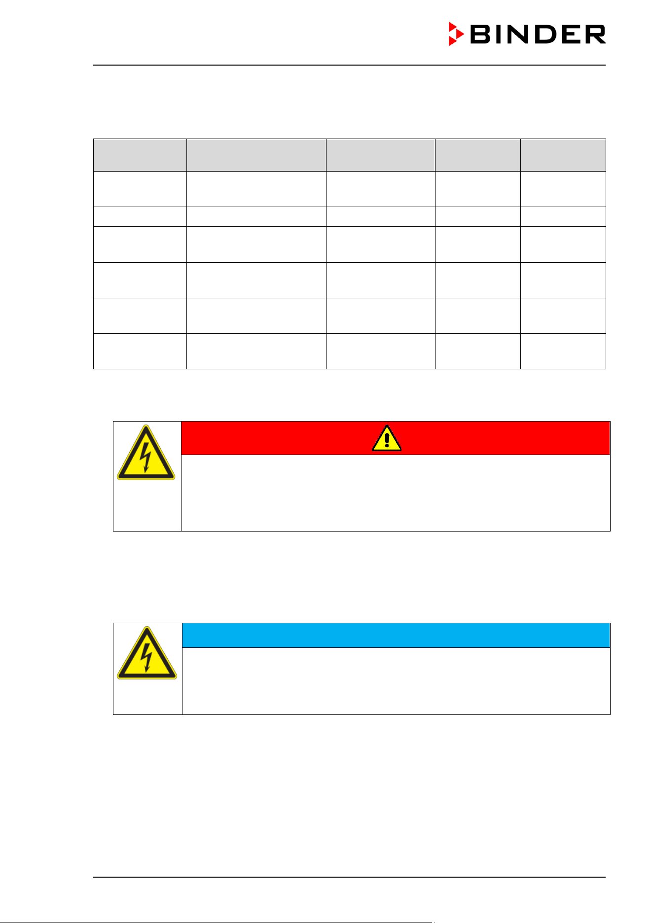
CB / CB-UL, CBF / CBF-UL (E7) 07/2022 Page 52/199
4.6 Electrical connection
The chambers are supplied ready for connection. They come with an IEC connector plug.
Model Power plug Voltage +/-10 %
Power
frequency
Chamber fuse
CB 56
Grounded plug
IEC 7/7
200-230 V (1N~) 50/60 Hz 10 A
CB 56-UL NEMA 5-20P 100-120 V (1N~) 50/60 Hz 12.5 A
CB 170
CBF 170
Grounded plug
IEC 7/7
200-230 V (1N~) 50/60 Hz 10 A
CB 170-UL
CBF 170-UL
NEMA 5-20P 100-120 V (1N~) 50/60 Hz 16 A
CB 260
CBF 260
Grounded plug
IEC 7/7
200-230 V (1N~) 50/60 Hz 10 A
CB 260-UL
CBF 260-UL
NEMA 5-20P 100-120 V (1N~) 50/60 Hz 16 A
• The domestic socket must also provide a protective conductor. Make sure that the connection of the
protective conductor of the domestic installations to the chamber’s protective conductor meets the latest
technology. The protective conductors of the socket and plug must be compatible!
DANGER
Electrical hazard due to missing protective conductor connection.
Deadly electric shock.
Make sure that the chamber’s power plug and the power socket match and securely
connect the electrical protective conductors of the chamber and the house
installation.
• Use only the original connection cables from BINDER according to the above specification.
UL chambers: Use only a UL Listed Power supply cord (UL category ELBZ), SJT 3x14 AWG (2.08 mm²).
For outside USA use a certified power supply cord according to national requirements.
• Prior to connection and start-up, check the power supply voltage. Compare the values to the specified
data located on the chamber’s type plate (left chamber side, bottom right-hand, see chap. 1.6).
NOTICE
Danger of incorrect power supply voltage due to improper connection.
Damage to the chamber.
Check the power supply voltage before connection and start-up.
Compare the power supply voltage with the data indicated on the type plate.
• When connecting the chamber, please observe the regulations specified by the local electricity supply
company as well as the local and national regulations (VDE directives for Germany).
• Make sure that there is sufficient current protection in accordance with the number of devices that are
to be operated. We recommend the use of a residual current circuit breaker.
• Pollution degree (acc. to IEC 61010-1): 2
• Over-voltage category (acc. to IEC 61010-1): II
See also electrical data (chap. 24.4).
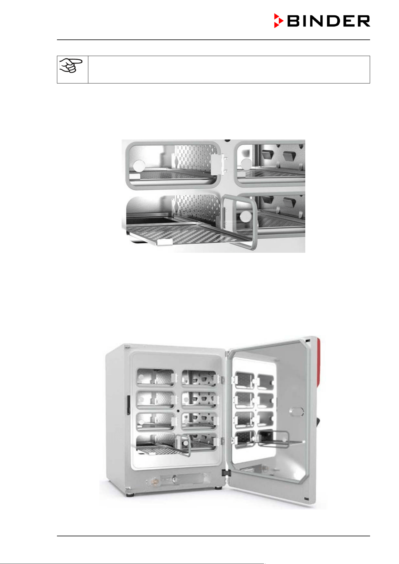
CB / CB-UL, CBF / CBF-UL (E7) 07/2022 Page 53/199
To completely separate the chamber from the power supply, you must disconnect the power
plug. Install the chamber in a way that the power plug is easily accessible and can be easily
pulled in case of danger.
4.7 Divided inner door with cell therapy compartmentation (optional)
With this option, the chambers are equipped with a divided inner door and additional dividers for
compartmentation to prevent mixing up of sample vessels.
Figure 26: A look inside an incubator
with the ”Divided inner door with cell therapy compartmentation” option
4.7.1 Special model CBF 260 “Cell Therapy”
As model variant CBF 260 “Cell Therapy” the chamber is equipped with O₂ control in the range of 0.2–20
Vol.-% and the divided inner door with cell therapy compartmentation.
Variant no.: 9640-0025 (230V) and 9640-0026 (120V)
Figure 27: CBF 260 “Cell Therapy”

CB / CB-UL, CBF / CBF-UL (E7) 07/2022 Page 54/199
4.7.2 Handling and aligning the divided inner door
Rubber profile gasket of
individual glass door of the
divided inner door
Hinge of the set-in divided inner
door, with elongated holes to
align the inner door
Measuring access port
Figure 28: Divided inner door (example: CB 170)
• Pull the handles to open each of the individual glass doors. Do not press too hard while closing them to
avoid pushing the doors through the gasket into the inner chamber.
• The rubber profile gaskets of the individual glass doors are easy to replace.
• If the divided inner door is not in an aligned position, fasten the hinge screws in the elongated holes of
the hinge to align it. Align the door and operate the locking smoothly.
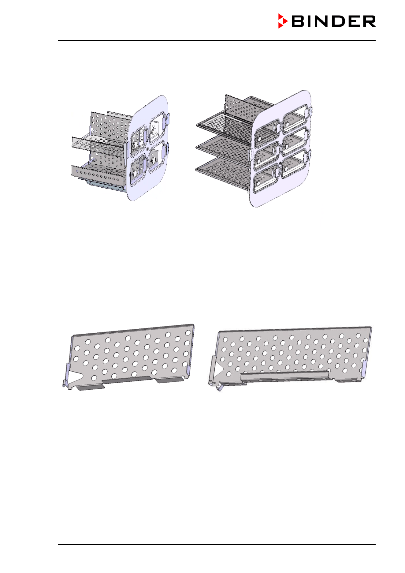
CB / CB-UL, CBF / CBF-UL (E7) 07/2022 Page 55/199
4.7.3 Mounting the partition walls for cell therapy compartmentation
Figure 29: Divided inner door with shelves and partition walls (example, chamber sizes 56 and 170)
The vertical partition wall is used to compartmentalize the interior of the chamber in connection with the
divided inner door. This spatially separates the samples.
The partition wall can be assembled or dismantled without tools and has a secure, vertical position. It can
also be used for chambers with the “Divided inner door” option.
Rear Front
Rear Front
Figure 30: Partition wall size 56 Figure 31: Partition wall size 170 / 260
For assembly, insert the lower rear end of the partition wall from above into the gap between the shelves
so that the rear end hooks onto the rear of the shelf holder.
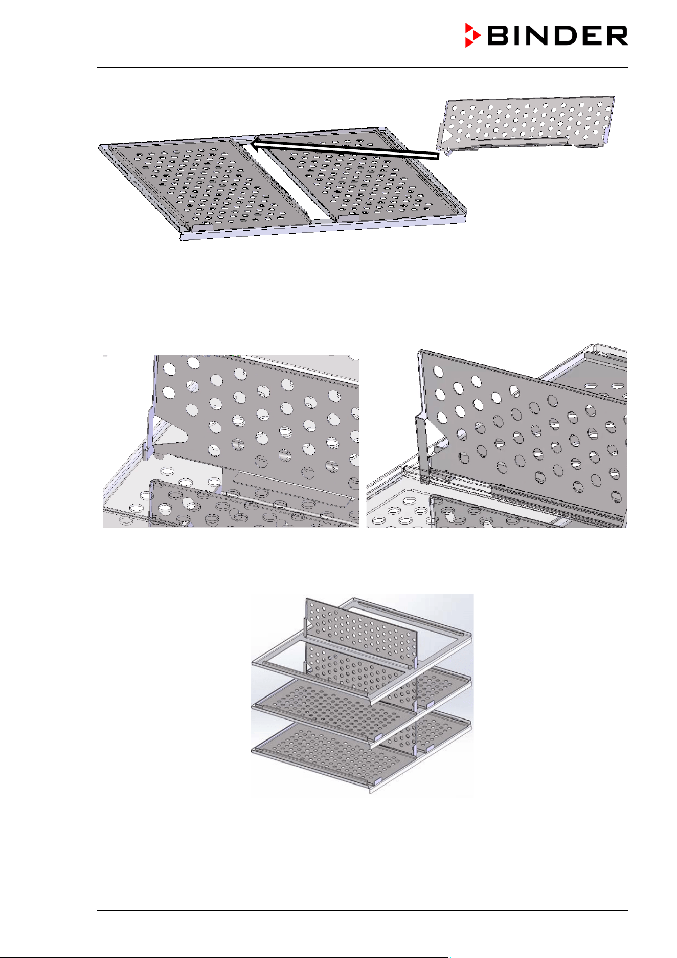
CB / CB-UL, CBF / CBF-UL (E7) 07/2022 Page 56/199
Figure 32: Inserting the partition wall
Then slide the partition towards the back of the chamber until it clicks into place.
Rear
Rear
Figure 33: Partition wall, size 56, assembled Figure 34: Partition wall, size 170 / 260, assembled
Figure 35: Shelf holder with inserted partition walls (example, size 170)
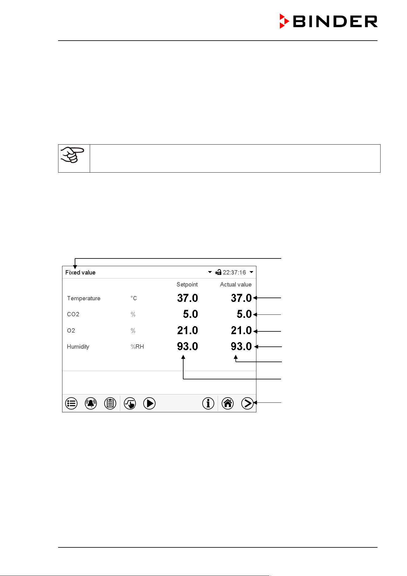
CB / CB-UL, CBF / CBF-UL (E7) 07/2022 Page 57/199
5. Functional overview of the MB2 chamber controller
The MB2 chamber controller controls following parameters inside the chamber:
• Temperature in °C
• Carbon dioxide concentration in vol.-%
• Oxygen concentration in vol.-% (chamber with O
2
control)
• Humidity in % r.h. (CBF / CBF-UL)
Note: In this manual the chambers are described in the maximum equipment variant and
including the available options. Therefore, some of the pictured and described features are
not available on every chambers
You can enter the desired set point values in fixed value operation mode directly on the display surface or
via the setpoint menu. For program operation the controller offers programming week and time programs.
In addition there is a timer program available (stopwatch function).
The controller offers various notifications and alarm messages with visual and audible indication and remote
alarms via e-mail, an event list (trace file) and the graphical display of the measuring values in the in der
chart recorder view. The MB2 program controller permits programming temperature and CO
2
/ O
2
and
humidity cycles (CBF / CBF-UL), and specifying special controller functions for each program section. You
can enter values or programs directly at the controller or use the APT-COM™ 4 Multi Management Software
(option) specially developed by BINDER.
Operating mode
Temperature values
CO
2
values
O
2
values (O
2
control)
Humidity values (CBF / CBF-
UL)
Actual values
Set-point values
Functional icons
Figure 36: Normal display of the MB2 program controller (sample values, CBF / CBF-UL with O
2
control)
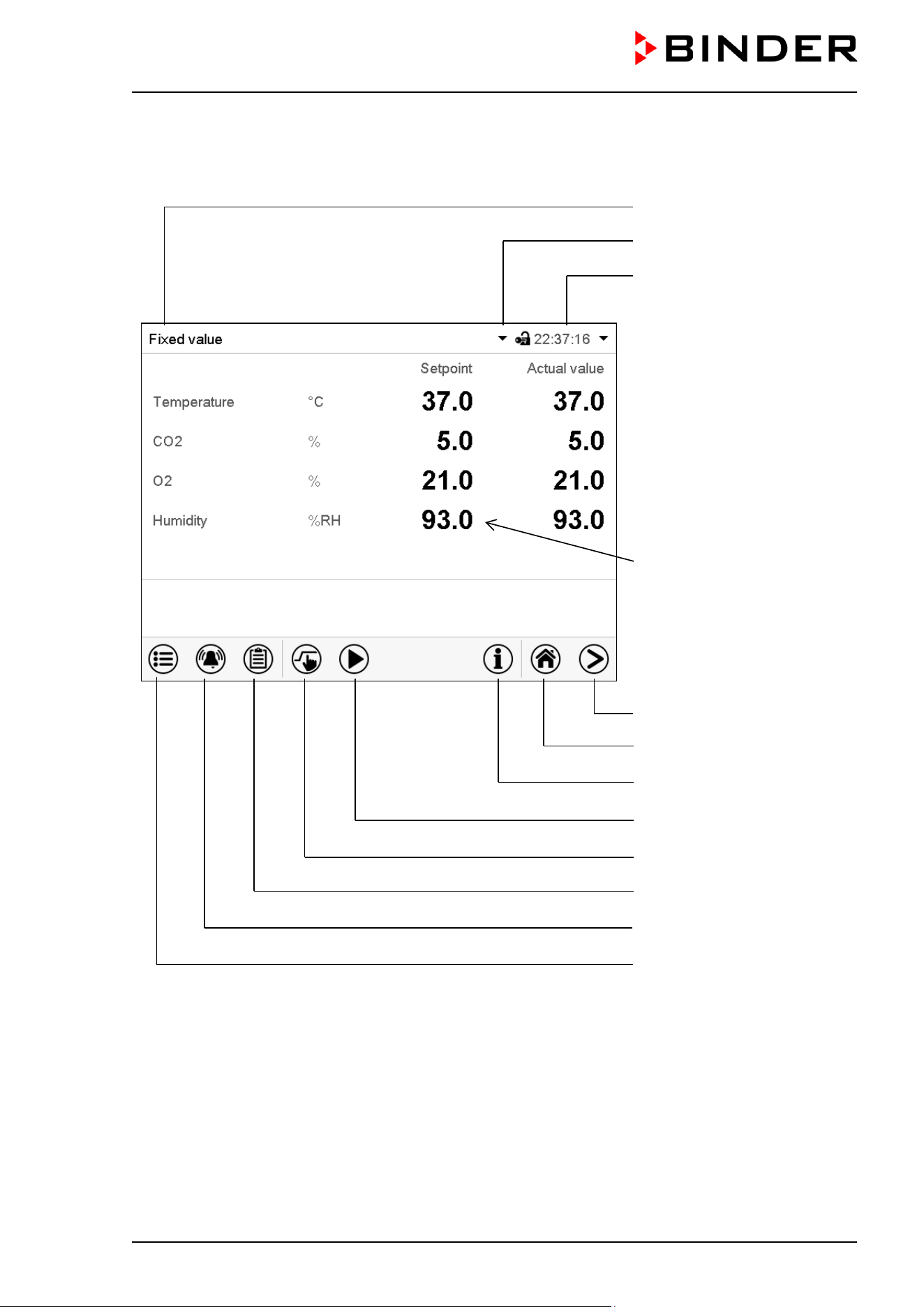
CB / CB-UL, CBF / CBF-UL (E7) 07/2022 Page 58/199
5.1 Operating functions in normal display
Current operating mode
Text list for information icons
Date, time, authorization level
of the logged-in user, memory
Quick setpoint entry
Continue to next screen
Back to Normal display
Information
Program start
Setpoint entry
Event list
Display of active alarms
Access to main menu
Figure 37: Operating functions of the MB2 controller in normal display (sample values, CBF / CBF-UL with
O
2
control)
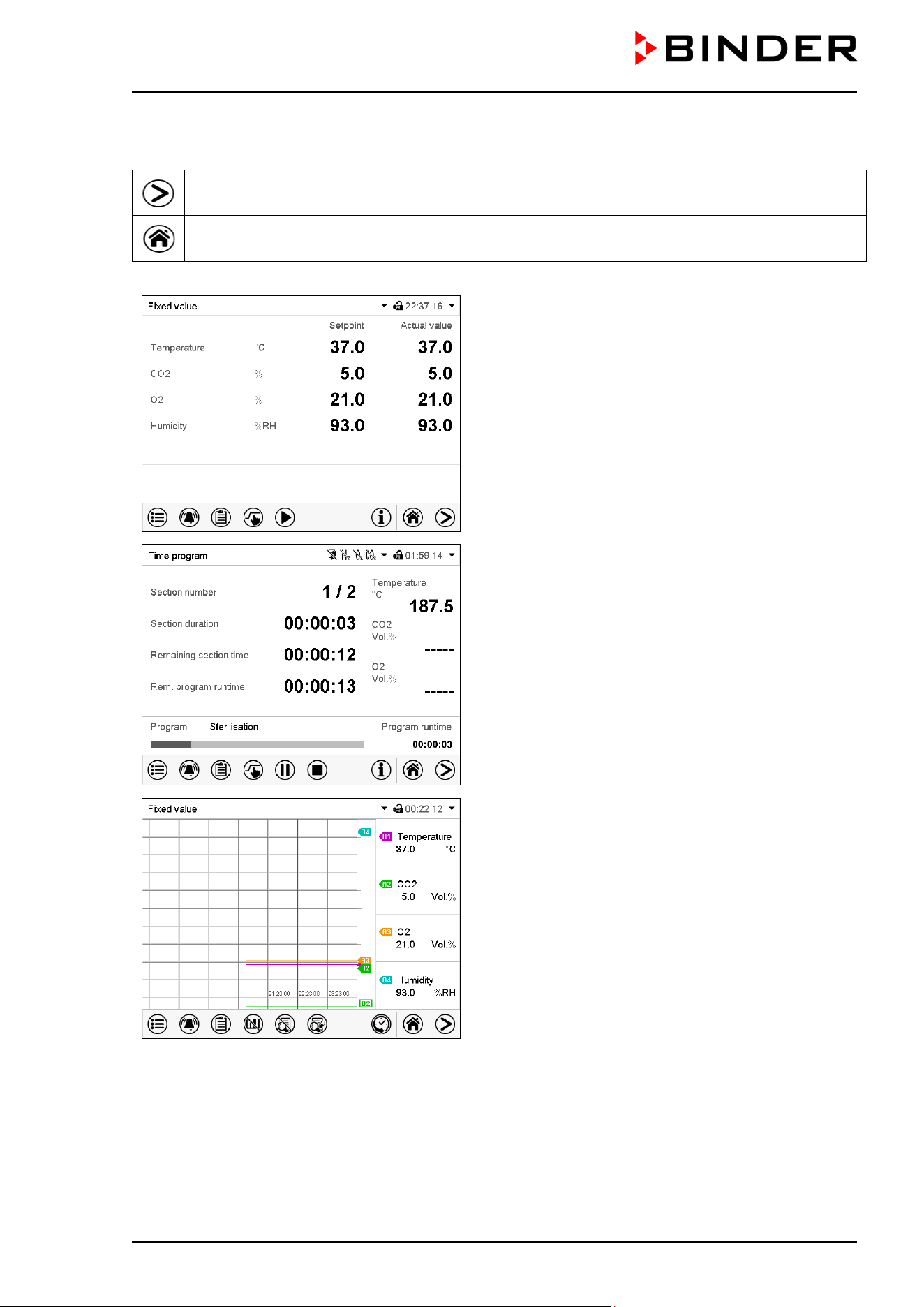
CB / CB-UL, CBF / CBF-UL (E7) 07/2022 Page 59/199
5.2 Display views: Normal display, program display, chart-recorder display
Press the Change view icon to toggle between normal display, program display and chart-
recorder display.
Press the Normal display icon to return from program display and chart recorder display back to
Normal display.
Normal display (actual values / setpoint values)
Program display (example: time program)
Chart recorder display
(Sample values, CBF / CBF-UL with O
2
control)
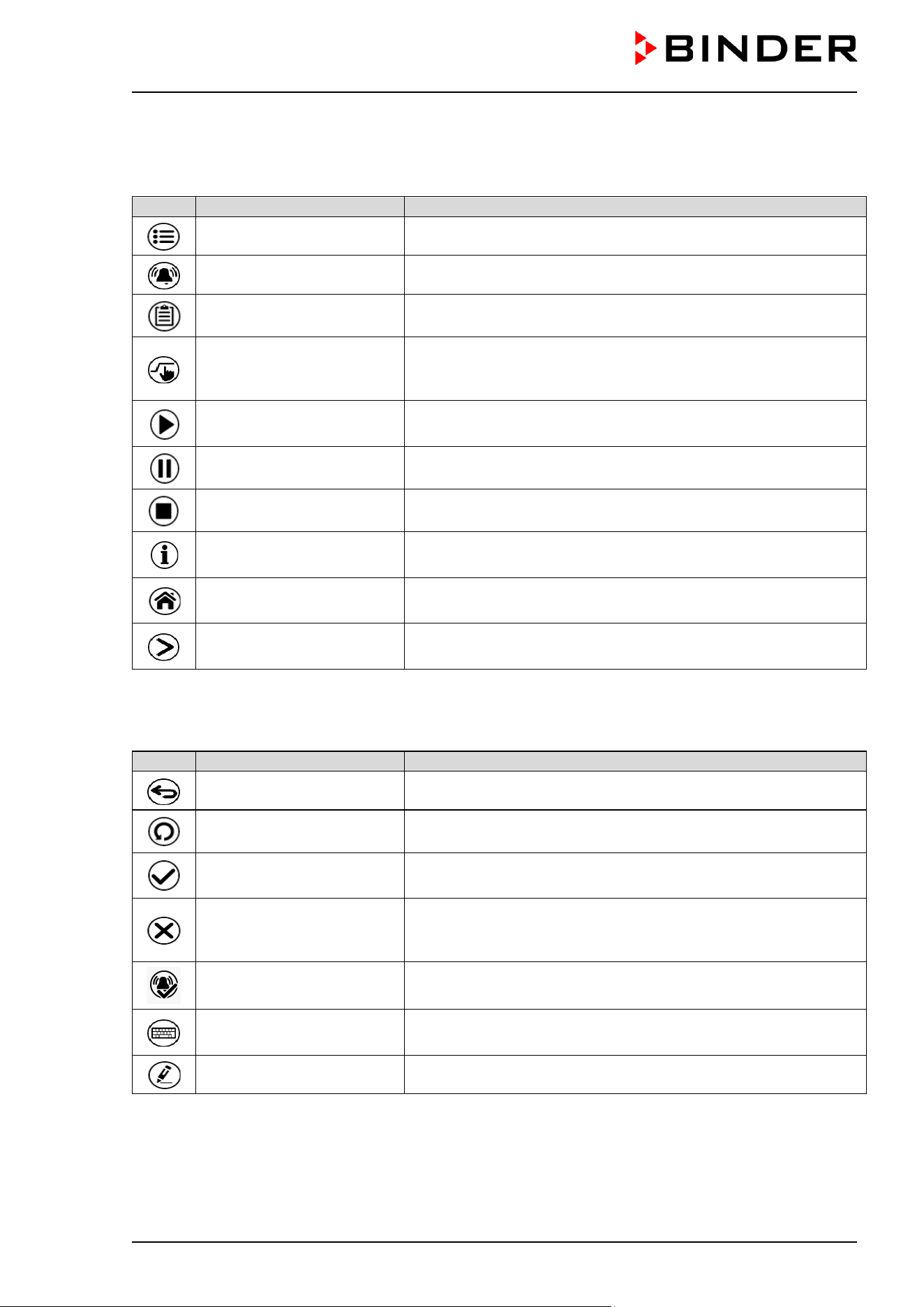
CB / CB-UL, CBF / CBF-UL (E7) 07/2022 Page 60/199
5.3 Controller icons overview
Navigation icons in Normal display
Icon
Signification
Function
Main menu Access from Normal display to the main menu
Alarm Access from Normal display to the list of active alarms
Event list Access from Normal display to the event list
Setpoint setting
Access from Normal display to the setpoint entry menu: setpoint
entry for Fixed value operation, turning on/off CO
2
/ O
2
and
humidity control, safety controller settings
Program start
Start a previously entered time or week program,
continue a paused time program
Program pause Pause a running time program
Program cancelling Cancel a running time or week program
Information
Information on program operation, setpoints, actual values, and
the safety controller
Normal display
Return from program display or chart recorder display to Normal
display
Change view
Toggle between Normal display, program display, and chart
recorder display
Functional icons in individual menus
Icon
Signification
Function
Back Return from each menu to Normal display
Update Update the event list and alarm messages
Confirm
Take over the entries and exit the menu / continue menu
sequence.
Close
Exit the menu / cancel menu sequence. Entries are not taken
over. When terminating a menu sequence, an information
window appears, which must be confirmed.
Reset alarm Acknowledge the alarm and mute the buzzer.
Change keyboard
Change between uppercase and lower case characters, digits
and special characters
Edit Edit settings of time and week programs
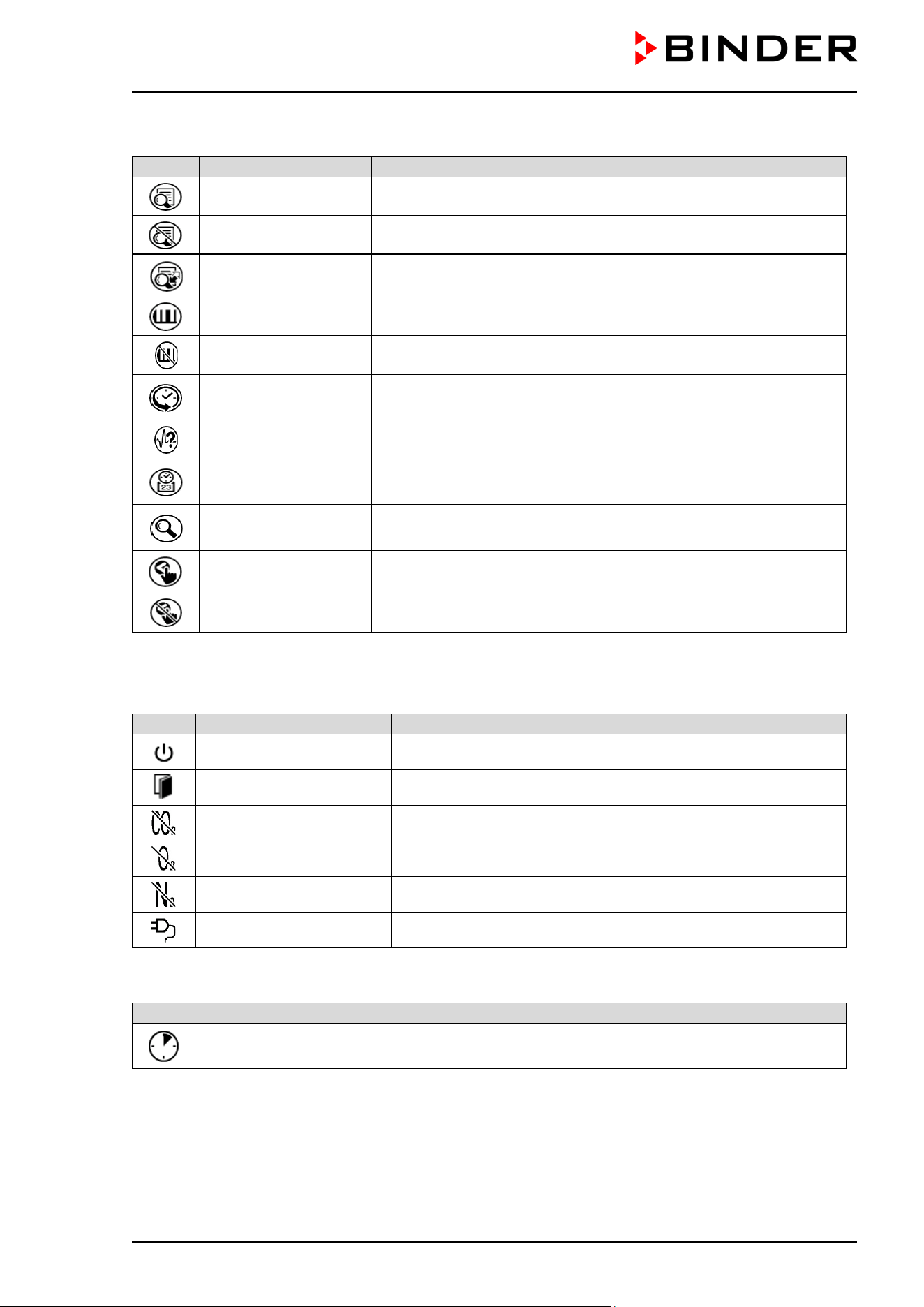
CB / CB-UL, CBF / CBF-UL (E7) 07/2022 Page 61/199
Functional icons in the chart recorder display
Icon
Signification
Function
Show legend Show legend
Hide legend Hide legend
Switch legend Switch between legend pages
Show indications Show indication “Door open” (B2)
Hide indications Hide indication “Door open” (B2)
History display
Pause chart recorder and change to history display. Data
recording continues.
Curve selection Go to “Curve selection” submenu in the history display
Search
Go to “Search” submenu in the history display to select the
required instant
Zoom
Go to “Zoom” submenu in the history display to select the zoom
factor
Show scroll buttons Show scroll buttons in the history display to scroll to an instant
Hide scroll buttons Hide scroll buttons in the history display to scroll to an instant
Information icons referring to chamber conditions
Icon
Text information
Condition
“Idle mode” Controller is in Idle mode
“Door open” Chamber door is open
“CO2 pressure alarm off” CO
2
pressure alarm deactivated
“O2 pressure alarm off” O
2
pressure alarm deactivated (chamber with O
2
control)
“N2 pressure alarm off” N
2
pressure alarm deactivated (chamber with O
2
control)
“Interior socket” Interior socket (option) activated
Information icon for data processing
Icon
Information
Waiting icon: Data processing is running.
Remaining time to touch the display when calibrating the touchscreen.
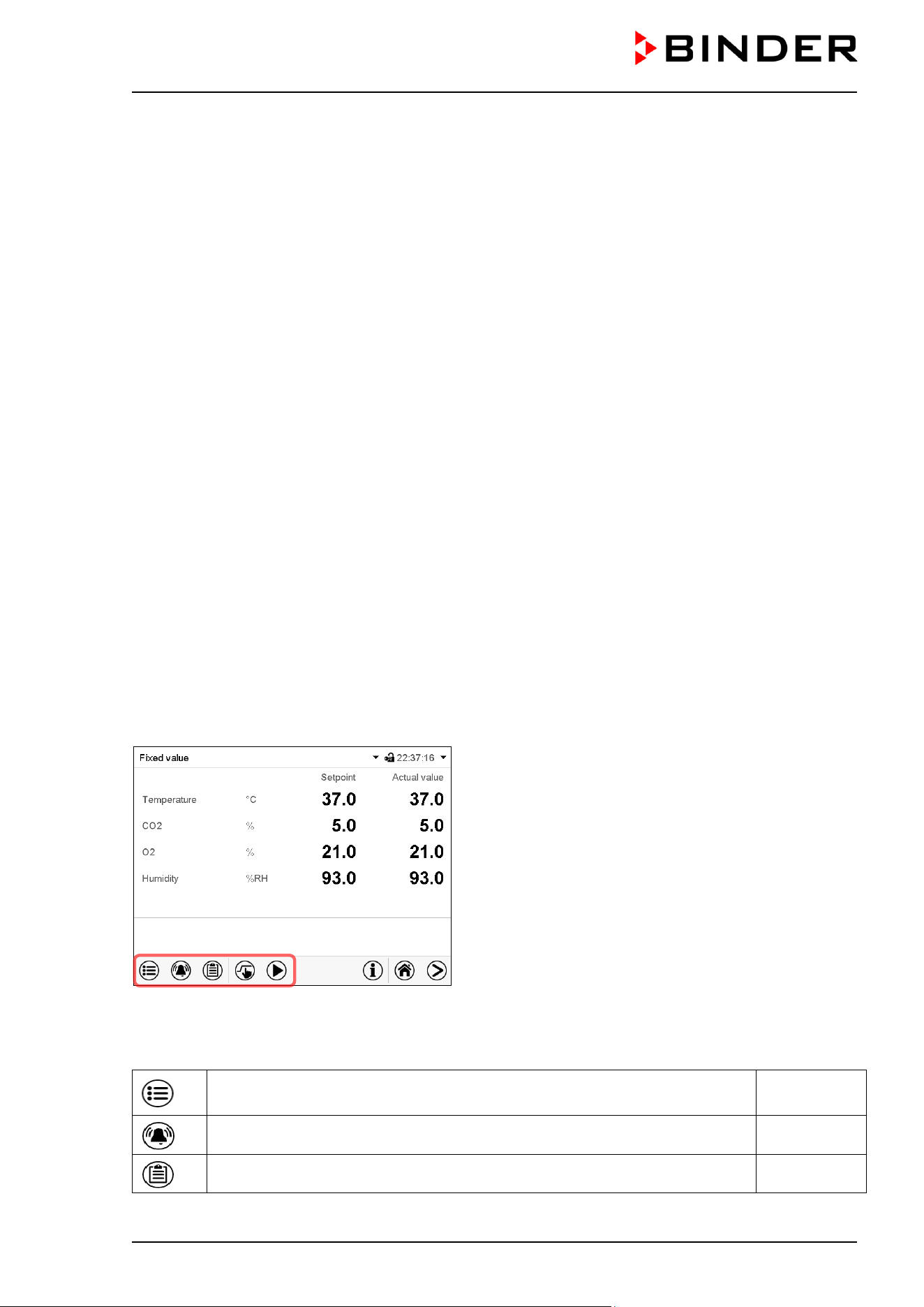
CB / CB-UL, CBF / CBF-UL (E7) 07/2022 Page 62/199
5.4 Operating modes
The MB2 program controller operates in the following operating modes:
• Idle mode
The controller is not functional, i.e., there is no heating, no CO
2
inlet or O
2
inlet (O
2
control) and no
humidification (CBF / CBF-UL). The chamber approximates ambient values.
You can activate and deactivate this operating mode with the “Idle mode” control contact in Fixed value
operating mode (chap. 7.3), time program operation (chap. 9.7.3) and week program operation (chap.
10.6.5).
• Fixed value operating mode
The controller operates as a fixed-point controller, i.e., set-points for temperature, CO
2
, O
2
(O
2
control)
and humidity (CBF / CBF-UL) can be defined, which are then maintained until the next manual change
(chap. 7.1).
• Timer program operation
Stopwatch function: during an entered duration the controller constantly equilibrates to the setpoints
entered in Fixed value operation mode.
• Time program operation
An entered time program for temperature, CO
2
, O
2
(O
2
control) and humidity (CBF / CBF-UL) is running.
The controller offers 25 program memory places with 100 program sections each. The total number of
program sections of all programs is unlimited
• Week program operation
An entered week program for temperature, CO
2
, O
2
(O
2
control) and humidity (CBF / CBF-UL) is running.
The controller offers 5 program memory places with 100 switching points each. The switching points
can be distributed over all days of the week.
5.5 Controller menu structure
Use the navigation icons in the screen footer in Normal display to access the desired controller functions.
The available functions depend on the current authorization level “Service”, “Admin” or “User” (chap.
13.1). This is selected either during login or can be available without password protection.
Main menu: program settings, further information, “Service” submenu.
The “Settings” submenu allows general configuration of the controller.
chap. 5.5.1
List of active alarms chap. 11
Access to the event list chap. 15.3
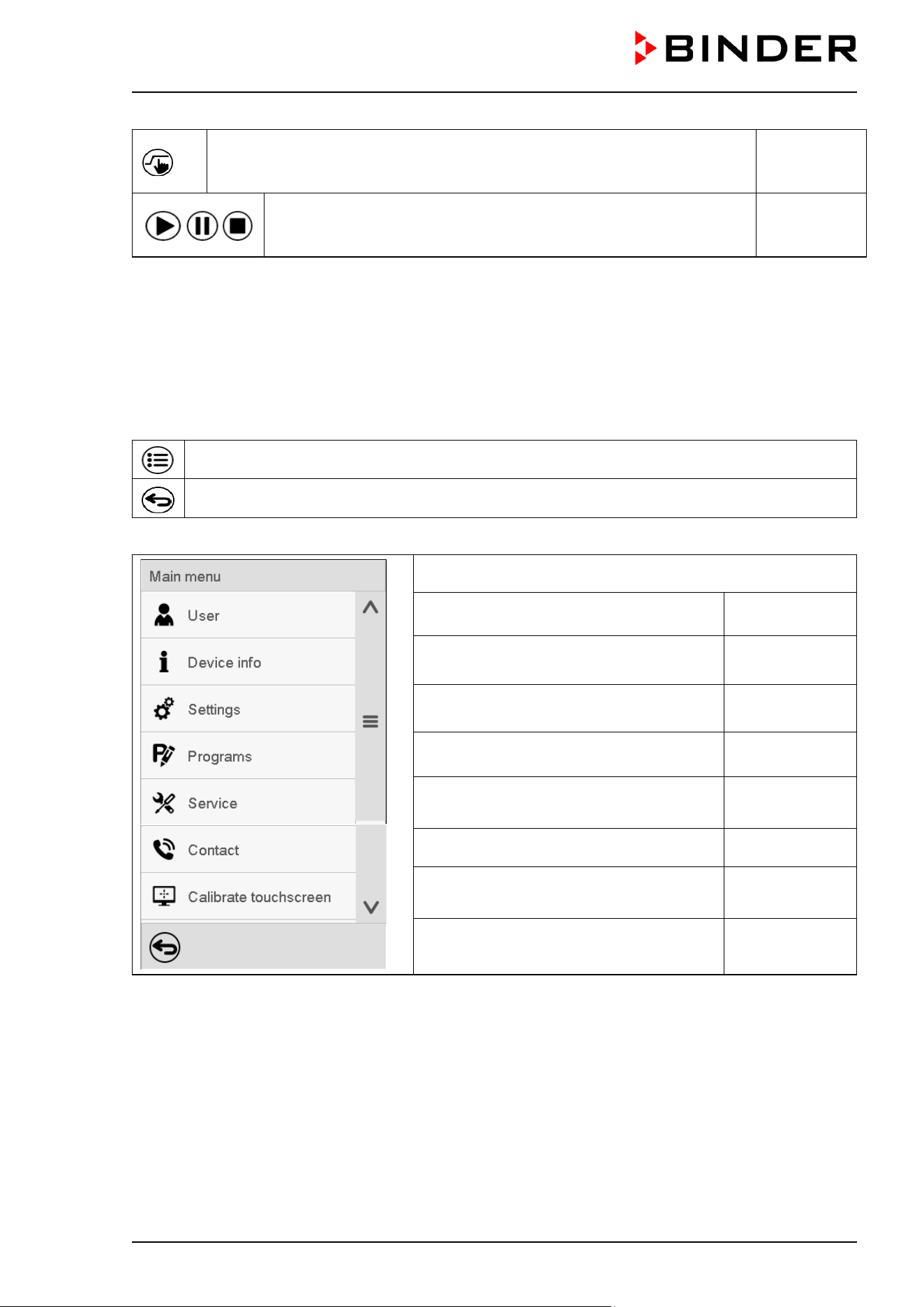
CB / CB-UL, CBF / CBF-UL (E7) 07/2022 Page 63/199
Setpoint entry for Fixed value operation, turning on/off CO
2
control, O
2
control (chamber with O
2
control) and humidity control (CBF / CBF-UL);
safety controller settings
chap. 7, 6.7,
12.2
Start/ pause/ cancel an already entered, respectively a running time
program or start / cancel an already entered, respectively a running
week program
chap. 9.1,
9.2, 10.1
Unless noted otherwise, the figures show the functional range, which is available for the user with “Admin”
authorization level.
5.5.1 Main menu
The main menu provides access to the general configuration of the controller as well as to program entry
and the user administration. Additionally there are support functions like a contact page or the display
calibration depending on the available angle.
Press the Main menu icon to access the main menu from Normal Display.
Press the Back icon to return from each setting menu to Normal Display.
The main menu provides the following functions and submenus.
User management: login and logout,
password management
chap. 13
Chamber information chap. 15.2
“Settings” submenu (not visible for user
with “User” authorization level)
chap. 14
Program entry submenu for time and week
programs
chap. 9 and 10
“Service” submenu chap. 5.5.3
BINDER Service contact page chap. 15.1
Calibrating the touch screen chap. 14.4.2
Back to Normal Display
“Settings” submenu
• Settings of many general controller functions and network settings (chap. 14).
• Available only for users with “Service” and “Admin” authorization level
“Service” submenu
• Access to service data, controller reset to factory settings (chap. 5.5.3)
• Available only for users with “Service” and “Admin” authorization level. Full functional range only for
BINDER Service (users with “Service” authorization level).
“Programs” submenu
• Access to the controller’s program functions (chap. 8, 9, 10)
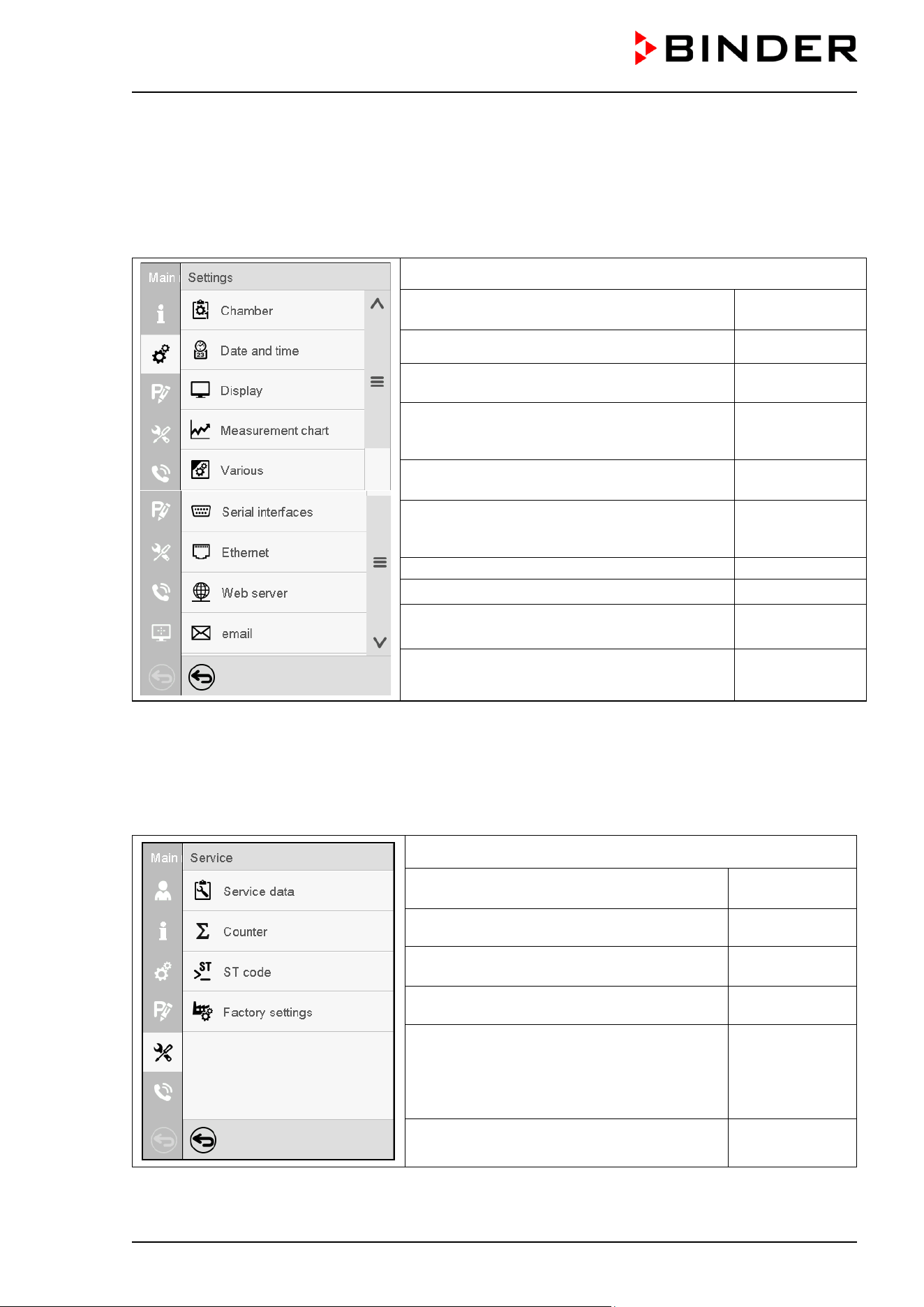
CB / CB-UL, CBF / CBF-UL (E7) 07/2022 Page 64/199
5.5.2 “Settings” submenu
The “Settings” submenu is available for users with “Service” or “Admin” authorization level. It serves to
enter date and time, select the language for the controller menus and the desired temperature unit and to
configure the controller’s communication functions.
Path: Main menu > Settings
Setting the temperature unit, menu
language…
chap. 14.1, 14.2
Setting date and time chap. 14.2
Setting the display brightness, continuous
operation and screen saver
chap. 14.4
Settings for the measurement chart: storage
interval, storage values, minimum and
maximum values
chap. 16.2
Setting the tolerance range and delay time for
tolerance range alarm
chap. 11.4
Configuration of the RS485 interface
(available via BINDER INDIVIDUAL
Customized Solutions)
chap. 14.5.1
Entry of the MAC address and IP address
chap. 14.5.2
Password protection for web server access chap. 14.5.3
Configuration of the e-mail server, assignment
of e-mail addresses
chap. 14.5.4
Back to main menu
5.5.3 “Service” submenu
The “Service” submenu is available for users with “Service” or “Admin” authorization level. When logged-in
with “Admin” authorization level the user will find information to tell the BINDER Service in service case.
Path: Main menu > Service
Serial number of the chamber, setup version
of the controller software
chap. 14.2
No function
Information for BINDER Service
Reset to factory settings
Back to main menu
(view with “Admin” authorization level)
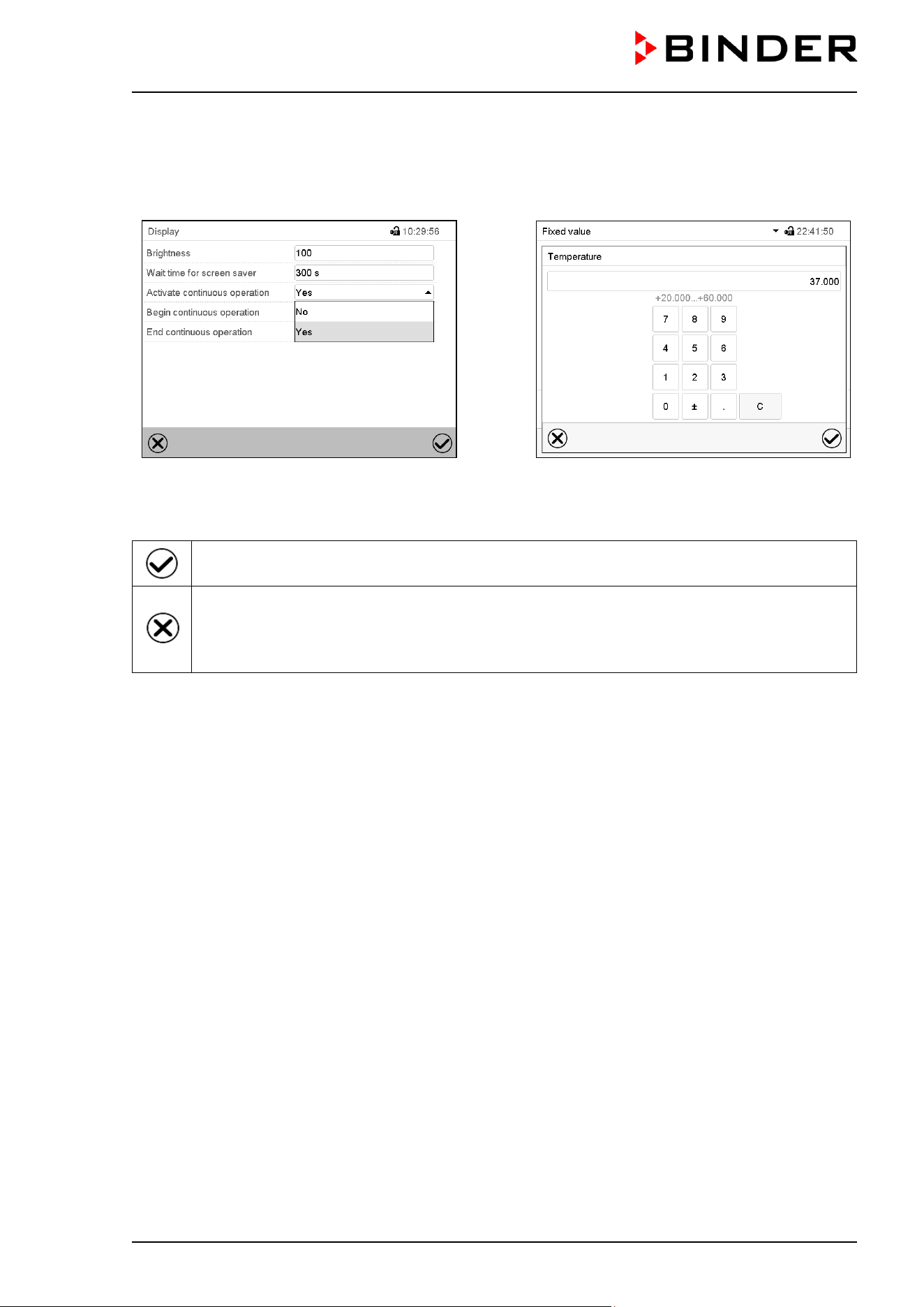
CB / CB-UL, CBF / CBF-UL (E7) 07/2022 Page 65/199
5.6 Principle of controller entries
In the selection and entry menus there are icons displayed in the footers which you can use to take over
the entry or cancel it.
Selection menu (example)
Entry menu (example)
After completing the settings there are the following possibilities:
Press the Confirm icon to take over the entries and exit the menu or continue the menu
sequence.
Press the Close icon to exit the menu or cancel the menu sequence without taking over the
entries.
When terminating a menu sequence, an information window appears, which must be
confirmed.
5.7 Performance during and after power failures
During a power failure, all controller functions are shut down. The gas inlet valves are closed so that no gas
can escape into the ambient air. The zero-voltage relay alarm output (3) (chap. 11.6) is switched to alarm
position for the whole duration of the power failure.
After the power returns, all functions return to the same status the chamber had before power failure. . The
controller continues to function in the original operating mode it was in previously before the power failure
occurred.
• Performance after power failure in Idle mode
Control is deactivated
• Performance after power failure in Fixed value operation mode
All functions return to the same status the chamber had before power failure. The set-points are
immediately resumed.
• Performance after power failure during time program operation
The program is resumed at the point where the interruption occurred with the latest set-points reached
during the program run.
• Performance after power failure during week program operation
The week program continues with the values corresponding to the current time.
• Performance after power failure during sterilization operation
The sterilization process is cancelled and the controller changes to Fixed value operation mode with the
setpoints already entered. All setpoint values remain in memory.
CB / CB-UL, CBF / CBF-UL (E7) 07/2022 Page 66/199
Power failure and power return are noted in the event list (chap. 15.3).
If during power failure the inner chamber temperature or the CO
2
/ O
2
concentration (chamber with O
2
control) or humidity (CBF / CBF-UL) has fallen below the alarm thresholds, confirm the alarms (e.g.,
tolerance range, safety controller). See chap. 11.3.
5.8 Performance when opening the door
When you open the door, CO
2
control and O
2
control (chamber with O
2
control) immediately turns off.
After 60 seconds from opening the door, the heating and humidification (CBF / CBF-UL) turn off.
After closing the door, heating, CO
2
control, O
2
control (chamber with O
2
control), humidification (CBF /
CBF-UL) turn on again.
6. Start up
6.1 Turning on the chamber
After connecting the supply lines (chap. 4), turn on the chamber by its main power switch. The lit pilot lamp
shows the chamber is ready for operation.
When the main power switch is turned on and yet the controller display is dark, the display is in stand-by
mode. Press on the touchscreen to activate it.
Check that the CO
2
control is activated (chap. 6.7).
CBF / CBF-UL: Fill the freshwater bag (chap. 4.5). Check that the humidifying system is activated (chap.
6.7).
After the first turning on of the chamber or after an interruption of the power supply the relative humidity will
increase after a delay of about 20 minutes. During this period, the relative humidity can drop considerably.
Chamber with O
2
control: Check that the O
2
control is activated (chap. 6.7).
Warming chambers may release odors in the first few days after commissioning. This is not a quality defect.
To reduce odors quickly we recommend heating up the chamber to its nominal temperature for one day
and in a well-ventilated location.
WARNING: If customer should use a BINDER chamber running in non-supervised
continuous operation, we strongly recommend in case of inclusion of irrecoverable specimen
or samples to split such specimen or samples and store them in at least two chambers, if
this is feasible.
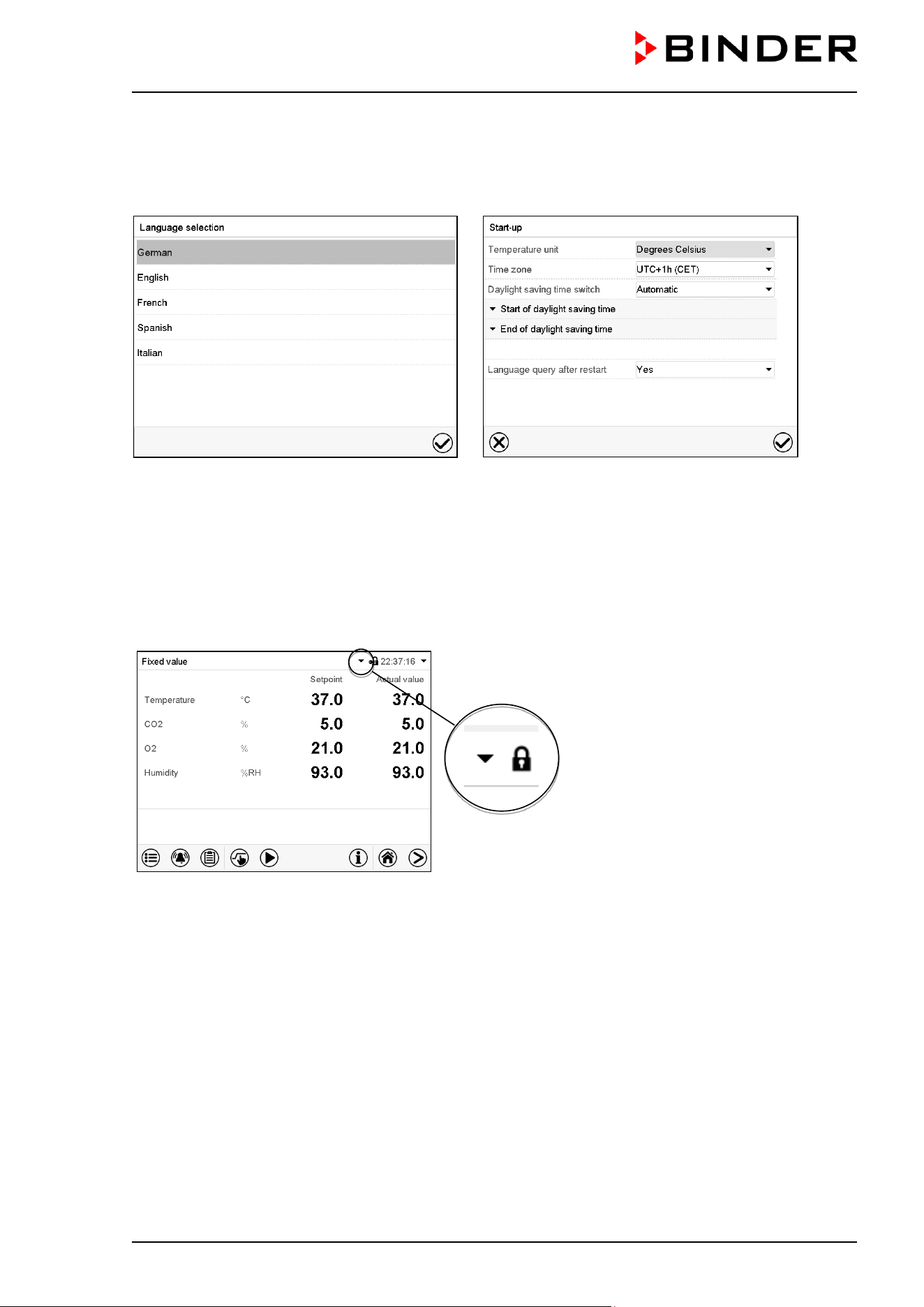
CB / CB-UL, CBF / CBF-UL (E7) 07/2022 Page 67/199
6.2 Controller settings upon start up
The window „Language selection“ enables the language selection, in case that it’s activated in the “Start-
up” menu. Afterwards occurs a request of the time zone and the temperature unit.
The controller will function in the operating mode, which was active before the last shut-down. It controls
temperature, CO
2
, O
2
(chamber with O
2
control) and humidity (CBF / CBF-UL) in fixed value operating
mode to the last entered values and in the program mode to the set points achieved beforehand.
Locked operation
Provided that the user administration has been activated by the assignment of passwords for the different
authorization types, the controller operation is first locked after turning on the unit, recognizable by the
closed lock icon in the header.
In the locked view the controller provides all display functions. No setting functions are available.
The setpoints are shaded (light grey) in normal display. Changing them by direct entry in the fixed value
operating mode is not possible. The functional icons for setpoint entry and program start in the footer are
without function.
After turning on the unit, user log-in is required to operate the controller (chap. 13.2)
Operation without user log-in / without password-protection
If the password function has been deactivated, after turning on the unit without user log-in there are those
controller functions available, which correspond to the highest authorization level without a password
protection. There is no lock icon in the header.
CB / CB-UL, CBF / CBF-UL (E7) 07/2022 Page 68/199
6.3 Factory settings
The chamber is supplied with the following basic preset parameters:
• Temperature setpoint 37 °C / 98.6 °F
• CO
2
setpoint 5 vol.-%
• O
2
setpoint (chamber with O
2
control) 21 vol.-%
• Humidity setpoint (CBF / CBF-UL) 93 % r.h.
• Safety controller class 3.1 Offset 2 °C
• Sterilization temperature (Set-point) 180 °C / 356 °F
• Audible alarm signal (buzzer) activated
The set temperature determines the target working temperature in the inner chamber, i.e. set value 37 °C
/ 98.6°F = target working temperature 37 °C / 98.6°F. The same is valid for the CO
2
and O
2
concentration
(chamber with O
2
control) and humidity (CBF / CBF-UL). For the hot-air sterilization, the set value is 180 °C
/ 356 °F and cannot be changed.
As long as there is a difference between the actual and set value shown in the display,
adequate operation of the chamber is not guaranteed.
6.4 Equilibration time
Temperature
• Equilibration time is max. 4 hours.
CO
2
• After turning in the chamber, after approx. 5 minutes the CO
2
concentration equilibrates automatically
to the pre-set value of 5 vol.-% CO
2
.
• Equilibration time is max. 0.5 hours.
O
2
(chamber with O
2
control)
• After turning in the chamber, the ambient oxygen concentration of approx. 20.9 vol.-% is displayed after
a delay of 10 minutes. During the first 10 minutes, O
2
control is not defined. Then O
2
is regulated to the
displayed setpoint value of 21 vol.-%.
• For high O
2
setpoint values (with alternative control range option), equilibration time is max. 1.5 hours.
Humidity (CB / CB-UL)
• With humidity control effected via the Permadry
®
system equilibration time is max. 15 hours
Humidity (CBF / CBF-UL)
• Equilibration time is max. 1 hour.
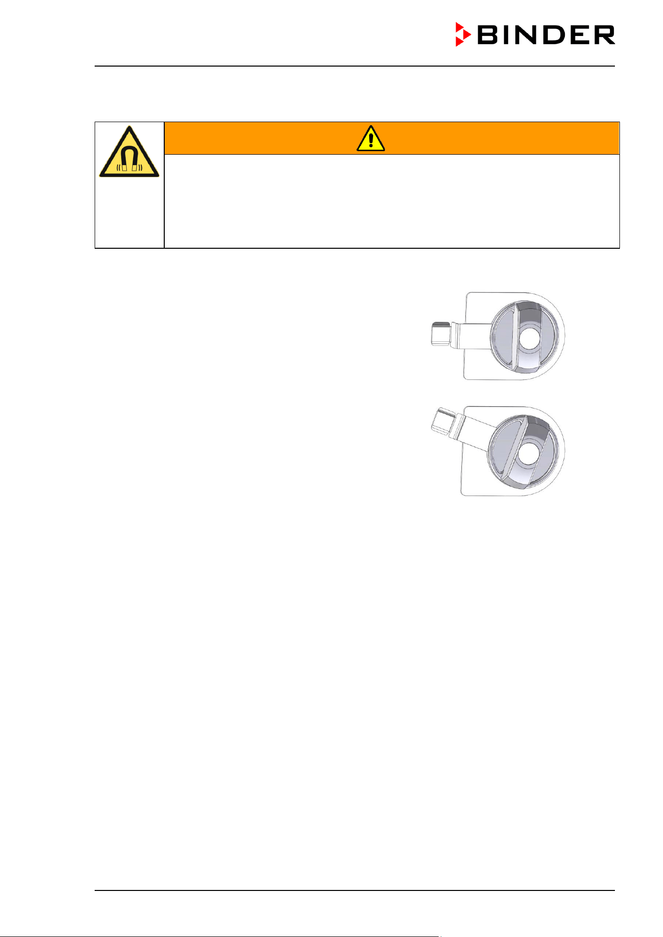
CB / CB-UL, CBF / CBF-UL (E7) 07/2022 Page 69/199
6.5 Operating the DuoDoor™ door lock
WARNING
Magnets can affect the function of pacemakers and implanted defibrillators.
A pacemaker can be put into test mode and cause discomfort. A defibrillator may
not work anymore.
If you wear such devices, maintain a sufficient safety distance to the chamber door in the
area of the door handle.
Warn wearers of such devices of approaching the chamber door.
The DuoDoor™ door lock offers two different ways to open the doors, dependent on the glass door lock
position.
Opening outer door and glass door independently
When closing the glass door, close the glass door lock.
Then you can close and open the outer door using its handle.
The glass door will remain closed until you manually open the
glass door lock.
Figure 38: Closed position
Opening outer door and glass together
When closing the glass door leave the glass door lock in open
position. Then close the outer door. The glass door is pressed
against the gasket so that both doors are securely closed.
When opening the outer door, a magnetic device also opens the
glass door.
Figure 39: Open position
6.6 Required gas supply for the chamber with O
2
control
In the chamber with O
2
control, cell growth can be additionally influenced by a variable oxygen content.
Depending on the required range of O
2
concentration, the type of gas which is required may vary. To this
end, two equipment variants are available:
6.6.1 Hypoxic control range 0.2 vol.-% up to 20 vol.- % O
2
(regular)
In addition to the CO
2
connection, the chamber provides a gas connection for N
2
.
As compared to the ambient air (O
2
concentration of 20.9 vol.-%) only the N
2
concentration needs to be
increased, no oxygen is required for the O
2
control. Therefore, it is not necessary and possible to connect
an O
2
cylinder. Even with activated O
2
control no O
2
pressure alarm will be emitted.
6.6.2 Alternative control range 10 vol.-% up to 95 vol.-% (option)
In addition to the CO
2
connection, the chamber provides gas connections for O
2
and N
2
.
• Operation in the hyperoxic range (> 22 vol.-% O
2
)
As compared to the ambient air (O
2
concentration of 20.9 vol.-%) only the O
2
concentration needs to be
increased, no nitrogen is required for the O
2
control. Therefore, it is not necessary to connect a N
2
cylinder.
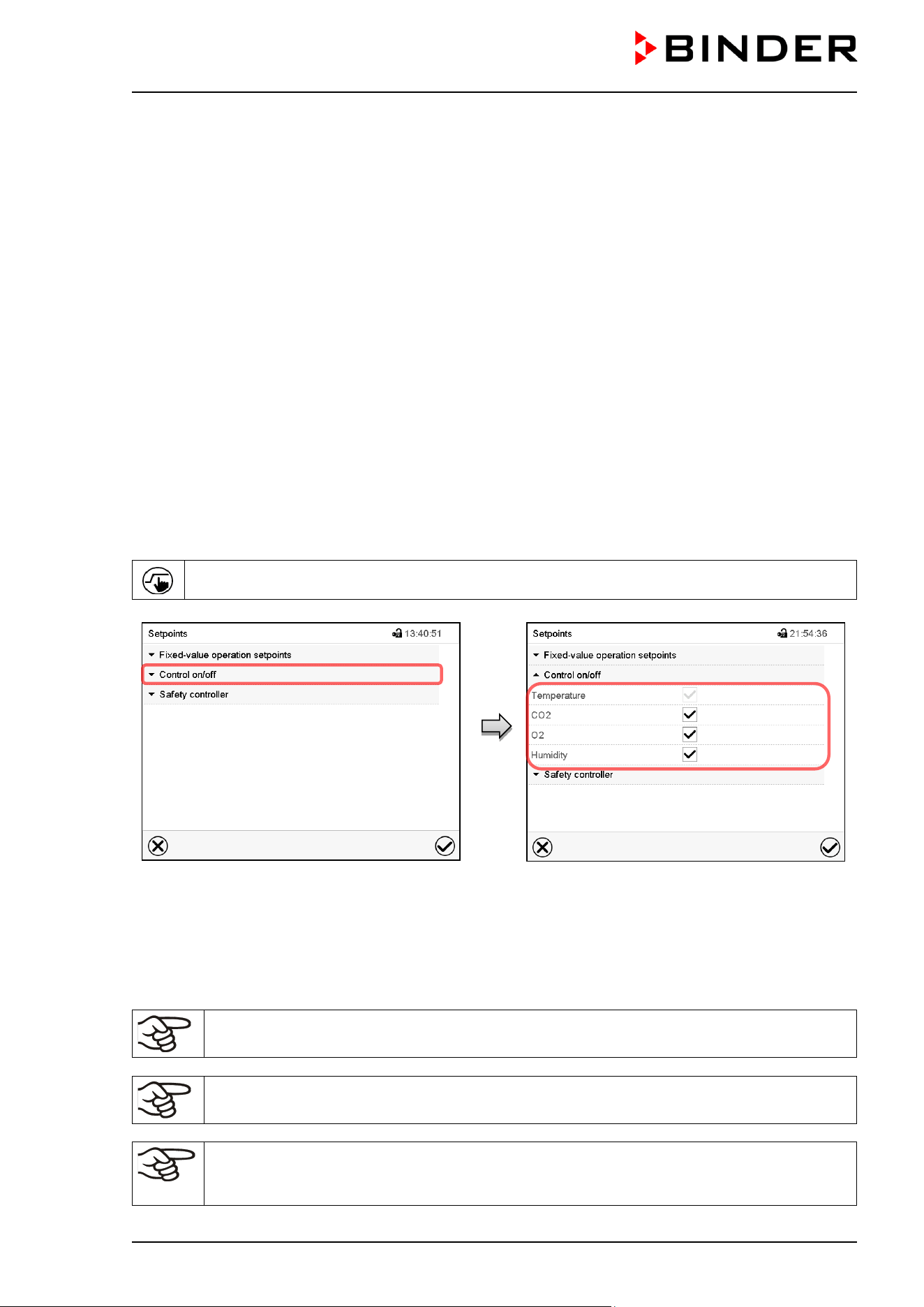
CB / CB-UL, CBF / CBF-UL (E7) 07/2022 Page 70/199
You can deactivate the N
2
pressure alarm in the controller (chap. 7.3). Then also with activated O
2
control no N
2
pressure alarm will be emitted.
• Alternating operation in the hyperoxic and hypoxic range or in the range from 20 vol.-% O
2
up to
22 vol.-% O
2
N
2
and O
2
are required for O
2
control. It is necessary to connect all gas supplies.
You can deactivate the O
2
and / or N
2
pressure alarm in the controller (chap. 7.3). Then also with
activated O
2
control no O
2
and / or N
2
pressure alarm will be emitted.
6.6.3 Operation without O
2
control
You can deactivate the O
2
control in the controller (chap. 6.7). With this setting, no O
2
and N
2
pressure
alarms and no O
2
tolerance range alarm will be issued. The zero-voltage relay alarm contact (chap. 11.6)
will also not be triggered.
Since neither nitrogen nor oxygen are required, it is not necessary to connect an O
2
or N
2
cylinder.
6.7 Activating / deactivating CO
2
, O
2
and humidity control
If CO
2
control and/or O
2
control (chamber with O
2
control) and/or humidity control (CBF / CBF-UL) shall not
be used, it is possible to deactivate them in the controller.
Press the Setpoint setting icon to access the “Setpoint” setting menu from Normal display.
“Setpoints” menu.
Select “Control on/off”.
You can turn on or off CO
2
control and O
2
control (chamber with O
2
control) and humidity
control (CBF / CBF-UL)
Mark / unmark the checkbox to activate /
deactivate the desired function and press the
Confirm icon.
When operating the chamber with deactivated CO
2
control, no CO
2
pressure alarm and no
CO
2
tolerance range alarm will be emitted.
Chamber with O
2
control: When operating the chamber with deactivated O
2
control, no O
2
and N
2
pressure alarms and no O
2
tolerance range alarm will be emitted.
CBF / CBF-UL: When operating the chamber with deactivated humidity control no humidity
tolerance range alarm will be emitted. The controller continues to show the actual humidity
value but no longer the humidity set-point.
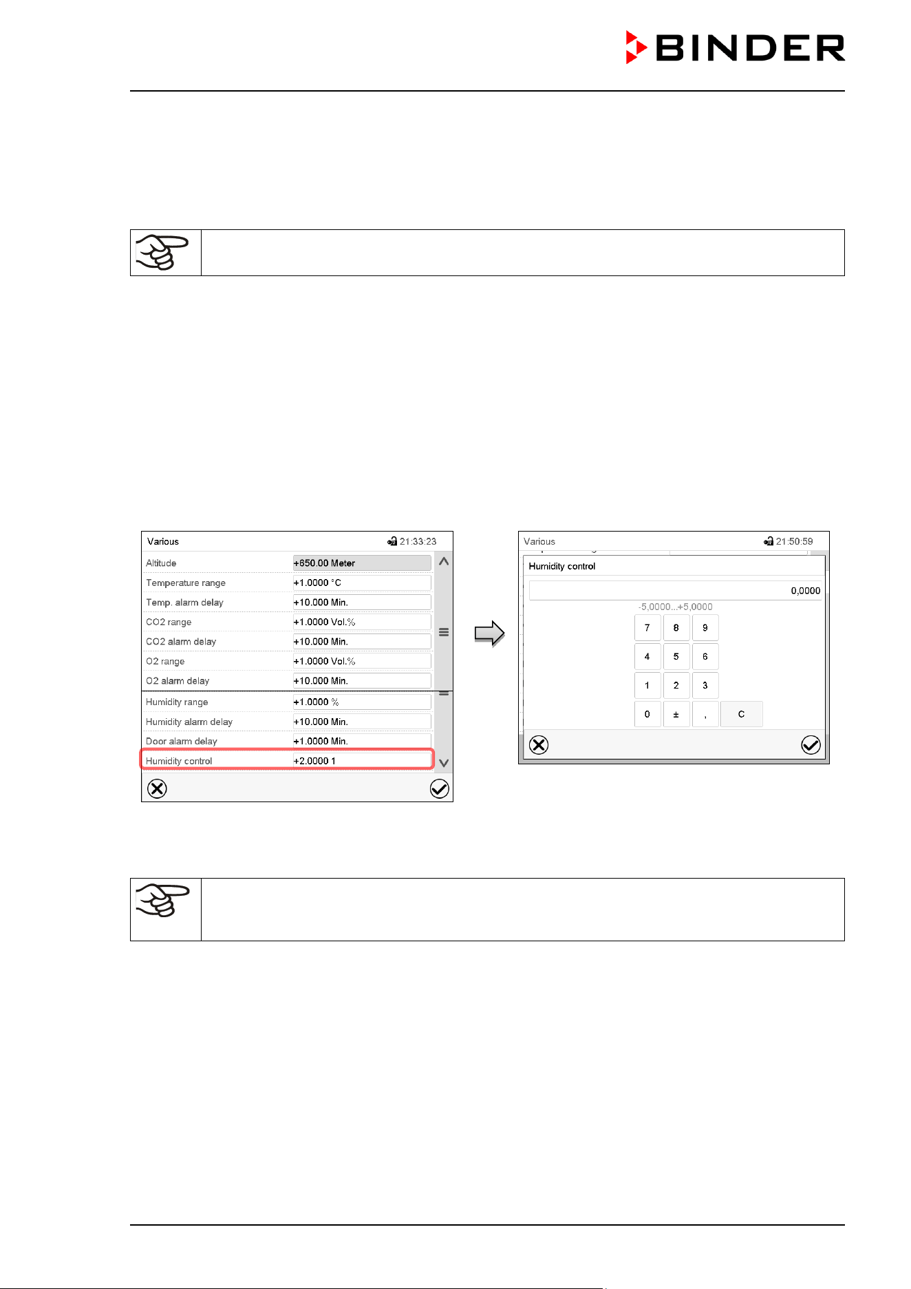
CB / CB-UL, CBF / CBF-UL (E7) 07/2022 Page 71/199
When operating the CBF / CBF-UL with deactivated humidity control, humidification can be realized using
the Permadry™ water pan (chap. 6.8).
6.8 CB / CB-UL: Humidity control of the Permadry™ system
With the CBF / CBF-UL, humidity setting via the Permadry™ System is not required.
The Permadry™ system with its 2-pan water system guarantees a maximum humidity of up to 95 % r.H. in
the inner chamber, which remains condensation-free. This performance assumes an average ambient
temperature of 22 +/- 3 °C / 71.6 +/- 5.4 °F and a working temperature in the inner chamber of 37 °C /
98.6 °F.
You can increase or decrease humidity slightly via the heating of the water pan if required.
Humidity is infinitely adjustable in whole numbers from -5 (low) to +5 (high).
Factory setting: “0” (medium).
Setting:
Path: Main menu > Settings > Various
Submenu “Various”.
Select the field “Humidity control”
“Humidity control” entry menu. Enter the desired
humidity and confirm entry with Confirm icon.
If the ambient temperature deviates by more than +/- 5 °C from the values recommended by
the manufacturer, the conditions for maximum air humidity with condensation-free inner
chamber are no longer guaranteed. Contact BINDER Service for assistance.
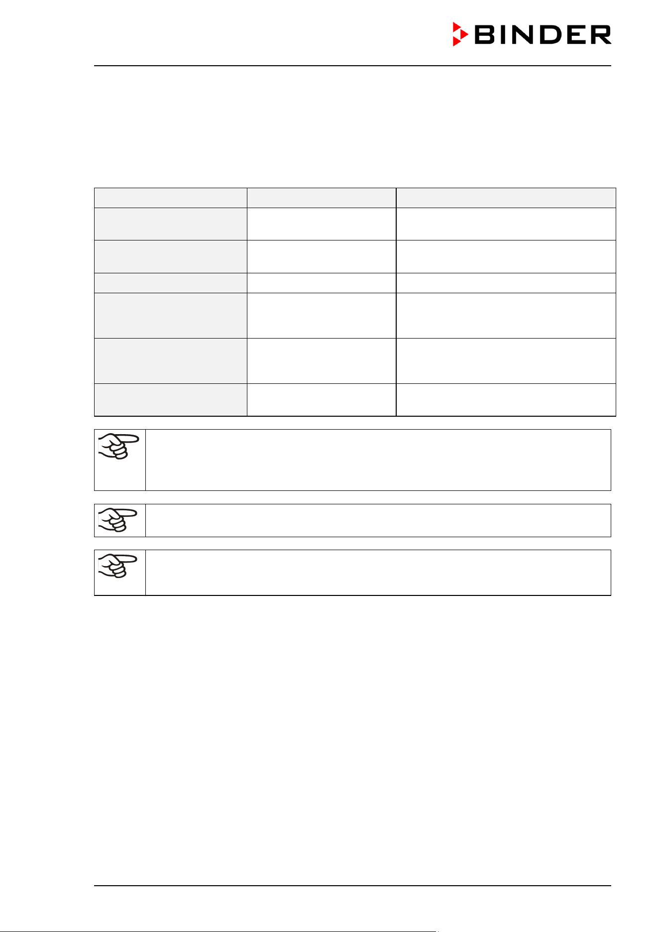
CB / CB-UL, CBF / CBF-UL (E7) 07/2022 Page 72/199
7. Set-point entry in “Fixed value” operating mode
In Fixed value operating mode you can enter set-points for temperature, CO
2
and O
2
(chamber with O
2
control) and humidity (CBF / CBF-UL), and the switching-state of up to 16 operation lines.
All settings made in Fixed value operating mode remain valid until the next manual change. They are saved
also when turning off the chamber or in case of toggling to Idle Mode or Program Mode.
Setting ranges Control ranges
Temperature
20 °C / 68 °F up to 60 °C /
140 °F
4 °C / 7.2 °F above ambient temperature
up to 60 °C / 140 °F
Temperature (chamber with
O
2
control)
20 °C / 68 °F up to 60 °C /
140 °F
6 °C / 10.8 °F above ambient temperature
up to 60 °C / 140 °F
CO
2
0 vol.-% up to 20 vol.- % 0 vol.-% up to 20 vol.- %
O
2
(chamber with O
2
control,
with regular hypoxic control
range)
0.2 vol.-% up to 21 vol.- % 0.2 vol.-% up to 20 vol.- %
O
2
(chamber with O
2
control,
with optional alternative
control range)
5 vol.-% up to 95 vol.-% 10 vol.-% up to 95 vol.-%
Humidity (CBF / CBF-UL) 50 % r.h. up to 95 % r.h.
50 % r.h. up to 95 % r.h.
(condensation-free up to 90 % r.h.)
With set-point type “Limit”, adapt the safety controller (chap. 12.2) always when you changed
the temperature set-point. Set the safety controller set-point by approx. 2 °C above the
controller temperature set-point.
Recommended setting: Set-point type “Offset” with safety controller set-point 2 °C.
When setting a lower temperature setpoint, in order to save time, we recommend cooling
down the chamber by turning it off and opening both chamber doors.
When setting a lower CO
2
, O
2
or humidity setpoint, the gas or humidity must be able to
escape first. Open both chamber doors for this purpose. Observe the precautions when
working with gases (chap. 1.9).
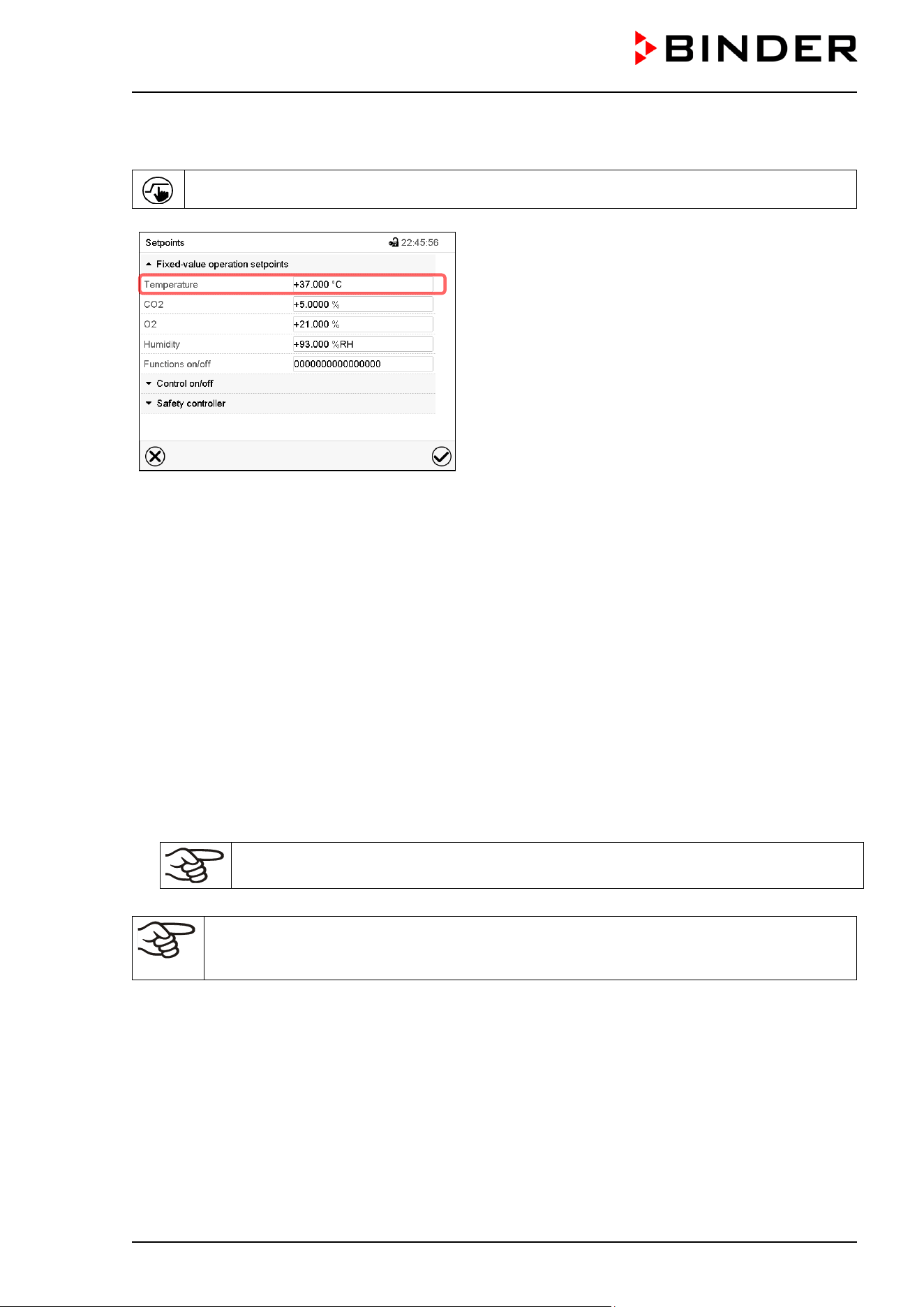
CB / CB-UL, CBF / CBF-UL (E7) 07/2022 Page 73/199
7.1 Set-point entry through the “Setpoints” menu
Press the Setpoint setting icon to access the “Setpoint” setting menu from Normal display.
“Setpoints” menu.
Select “Fixed value operation setpoints” to access the
individual parameters.
• Select the field “Temperature” and enter the desired temperature setpoint.
Setting range: 20 °C up to 60 °C. Confirm entry with Confirm icon.
• Select the field “CO2” and enter the desired CO
2
setpoint.
Setting range: 0 vol.-% up to 20 vol.-%.
Confirm entry with Confirm icon.
Chamber with O
2
control:
• Select the field “O2” and enter the desired O
2
setpoint.
Setting range with regular hypoxic control range: 0.2 vol.-% up to 20 vol.-%.
Setting range with alternative control range: 5 vol.-% up to 95 vol.-%.
Confirm entry with Confirm icon.
CBF / CBF-UL:
• Select the field “Humidity” and enter the desired humidity setpoint.
Setting range: 50 % r.h. up to 95 % r.h. Confirm entry with Confirm icon.
When entering a humidity setpoint value > 90 % r.h. a message window appears,
indicating that condensation is possible. Press the Confirm icon.
When entering a setpoint value outside the setting range, the message: “Value outside of
limits! (Min: xxx, Max: xxx)” appears (xxx is a wildcard for the limits of the respective
parameter). Press the Confirm icon and repeat the entry with a correct value.
After completing the settings, press the Confirm icon to take over the entries and exit the menu, or press
the Close icon to exit the menu without taking over the entries.
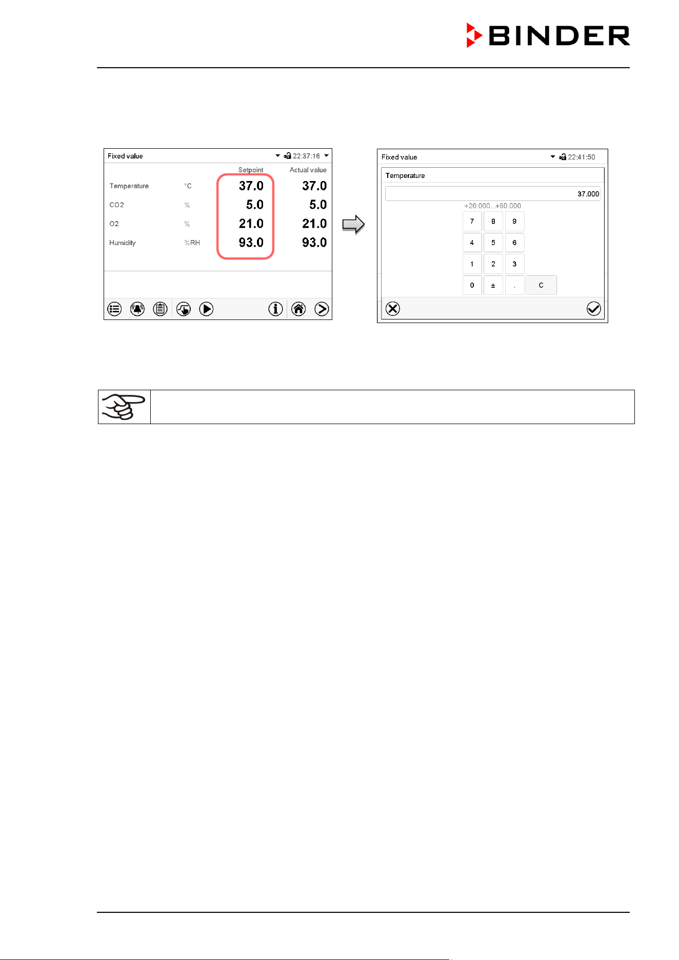
CB / CB-UL, CBF / CBF-UL (E7) 07/2022 Page 74/199
7.2 Direct setpoint entry via Normal display
Alternatively you can also enter the setpoints directly via Normal display.
Normal display. Select the setpoint you want
to change.
Example: “Temperature” entry menu. Enter the
desired setpoint and confirm entry with Confirm
icon.
When entering a humidity setpoint value > 90 % r.h. a message window appears, indicating
that condensation is possible. Press the Confirm icon.
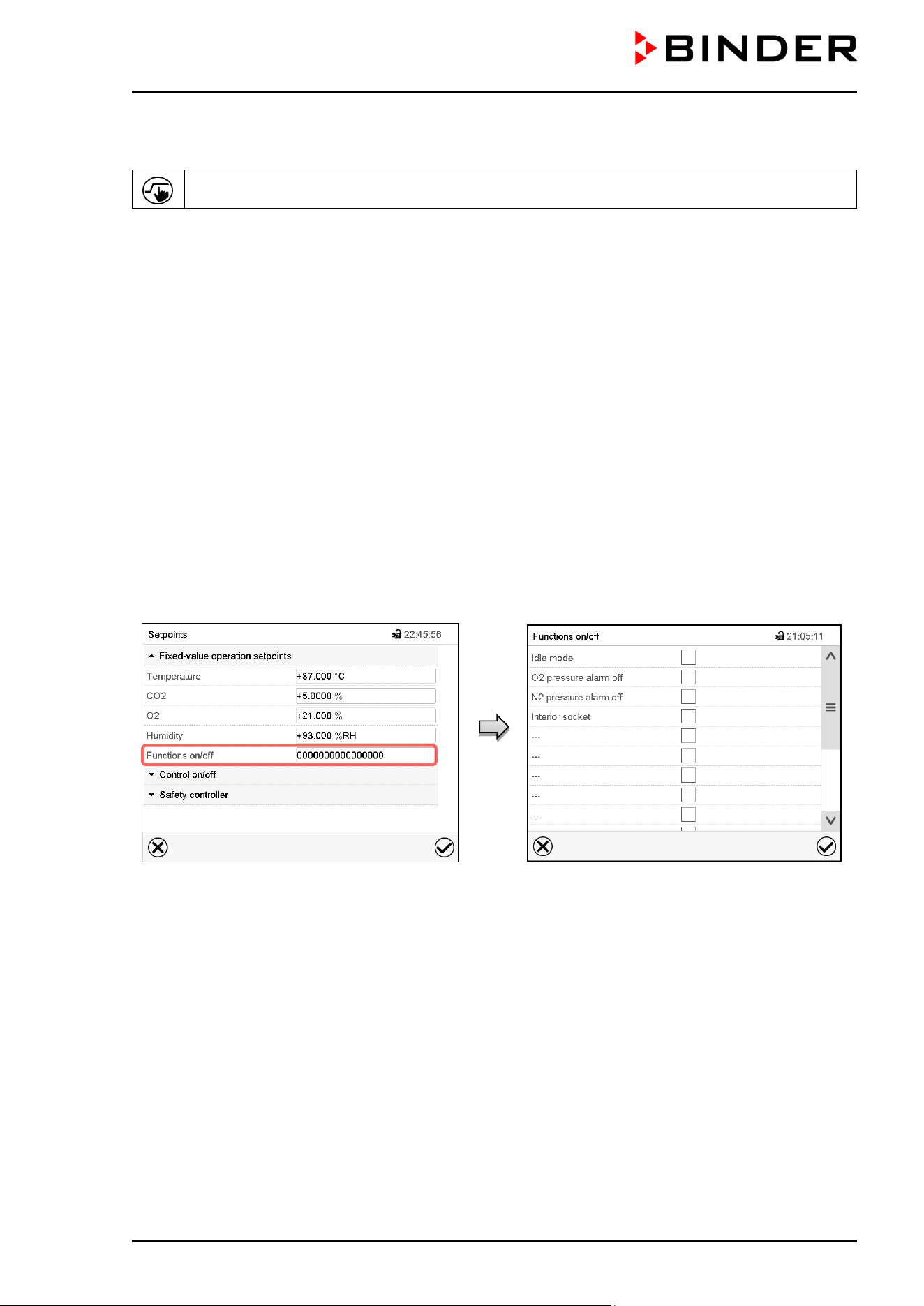
CB / CB-UL, CBF / CBF-UL (E7) 07/2022 Page 75/199
7.3 Special controller functions via operation lines
Press the Setpoint setting icon to access the “Setpoint” setting menu from Normal display.
You can define the switching state of up to 16 operation lines (control contacts). They are used to activate
/ deactivate special controller functions.
Chamber with O
2
control: Depending on the required range of O
2
concentration, the type of gas which is
required may vary (chap. 6.6). Therefore, the pressure alarms for O
2
and N
2
can be deactivated individually
with active O
2
control.
For chambers equipped with the optional interior socket (chap. 18.4) you can turn on and off the voltage of
the interior socket via the controller.
• Operation line “Idle mode” activates / deactivates the operating mode “Idle mode”.
• Operation line “O2 pressure alarm off” activates / deactivates the O
2
pressure alarm (chamber with O
2
control and optional alternative control range)
• Operation line “N2 pressure alarm off” activates / deactivates the N
2
pressure alarm (chamber with O
2
control)
• Operation line “Interior socket” activates / deactivates interior socket (option, available via BINDER
INDIVIDUAL Customized Solutions)
The other operation lines are without function.
Use the “Setpoints” menu to configure the operation lines.
“Setpoints” menu.
Select the field “Functions on/off”.
“Functions on/off” entry menu (view with
chamber with O
2
control with optional interior
socket).
Mark / unmark the checkbox to activate /
deactivate the desired function and press the
Confirm icon
Activated operation line: switching status “1” (On)
Deactivated operation line: switching status “0” (Off)
The operation lines count from right to left.
Example:
Activated operation line “Idle mode” = 000000000000000
1
Deactivated operation line “Idle mode” = 000000000000000
0
CB / CB-UL, CBF / CBF-UL (E7) 07/2022 Page 76/199
7.4 Safety instructions for setting high gas concentrations
Notes on handling carbon dioxide (CO
2
)
Carbon dioxide (CO
2
) in high concentrations is hazardous to health. It is colorless and almost odorless and
therefore practically imperceptible. Vent out any CO
2
gas that may escape via good room ventilation or a
suitable connection to an exhaust system. We recommend installing a CO
2
warning system.
DANGER
Danger of suffocation and poisoning by high concentration of CO
2
(> 4 Vol.-%).
Death by suffocation.
∅ Do NOT set up chambers in non-ventilated recesses.
Ensure technical ventilation measures.
Observe the relevant regulations for handling CO
2
.
Close the CO
2
supply when decommissioning the chamber.
If CO
2
is released, leave the area und inform the security service or fire department.
Chamber with O
2
control: Notes on handling oxygen (O
2
)
Oxygen (O
2
) is colorless and almost odorless and therefore practically imperceptible. It promotes burns,
which can proceed explosively. There is a fire hazard for flammable oxygenated materials, e.g. clothes and
hair. O
2
is heavier than air and may accumulate in low-lying areas.
DANGER
Danger of fire and explosion through contact of combustible materials with O
2
with high concentration of O
2
(> 21 % O
2
).
Serious injury or death from burns and / or explosion pressure.
∅ Do NOT set up chambers in non-ventilated recesses.
Ensure technical ventilation measures.
Observe the relevant regulations for handling O
2
.
Close the O
2
supply when decommissioning the chamber.
Take appropriate measures to prevent oxygen enrichment and fire and explosion hazards in areas where
oxygen enrichment is possible.
Observe the general information for safe handling of oxygen (chap. 1.9).
Chamber with O
2
control: Notes on handling nitrogen (N
2
)
Nitrogen (N
2
) in high concentrations is hazardous to health. It is colorless and almost odorless and therefore
practically imperceptible. Any N
2
gas that may escape must be safely led out via good room ventilation or
a suitable connection to an exhaust system.
DANGER
Risk of suffocation through high concentration of N
2
.
Death by suffocation.
∅ Do NOT set up chambers in non-ventilated recesses.
Ensure technical ventilation measures.
Observe the relevant regulations for handling N
2
.
Close the N
2
supply when decommissioning the chamber.
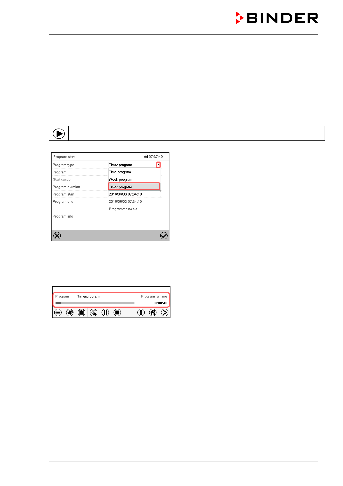
CB / CB-UL, CBF / CBF-UL (E7) 07/2022 Page 77/199
8. Timer program: stopwatch function
During an entered duration the controller constantly equilibrates to the setpoints entered in Fixed value
operation mode (temperature, CO
2
, O
2
(chamber with O
2
control), humidity (CBF / CBF-UL), configuration
of the operation lines). This duration can be entered as a “Timer program”. During the program runtime,
any setpoint changes do not become effective; the controller equilibrates to the values which were active
during program start.
8.1 Starting a timer program
In Normal display press the Program start icon to access the “Program start” menu.
“Program start” menu
• In the field “Program type” select “Timer program”.
• Select the field “Program duration” and enter the desired program duration. Press the Confirm icon.
• Select the field “Program start” and enter the desired start time of the program in the “Program start”
entry menu. Press the Confirm icon. The program delay time until program start begins.
Normal display.
Information on the bottom of the screen indicates the
currently running program and the time already
passed. The grey bar shows how much time of the
whole time is elapsed.
8.1.1 Performance during program delay time
During the configured program delay time until program start, the controller equilibrates to the current
setpoints of Fixed value operation mode. Modifications of these setpoints are possible but become effective
only after the timer program is finished. When the configured moment for program start is reached, the
program delay time ends and the program starts running. The controller equilibrates to the values which
had been active during program start
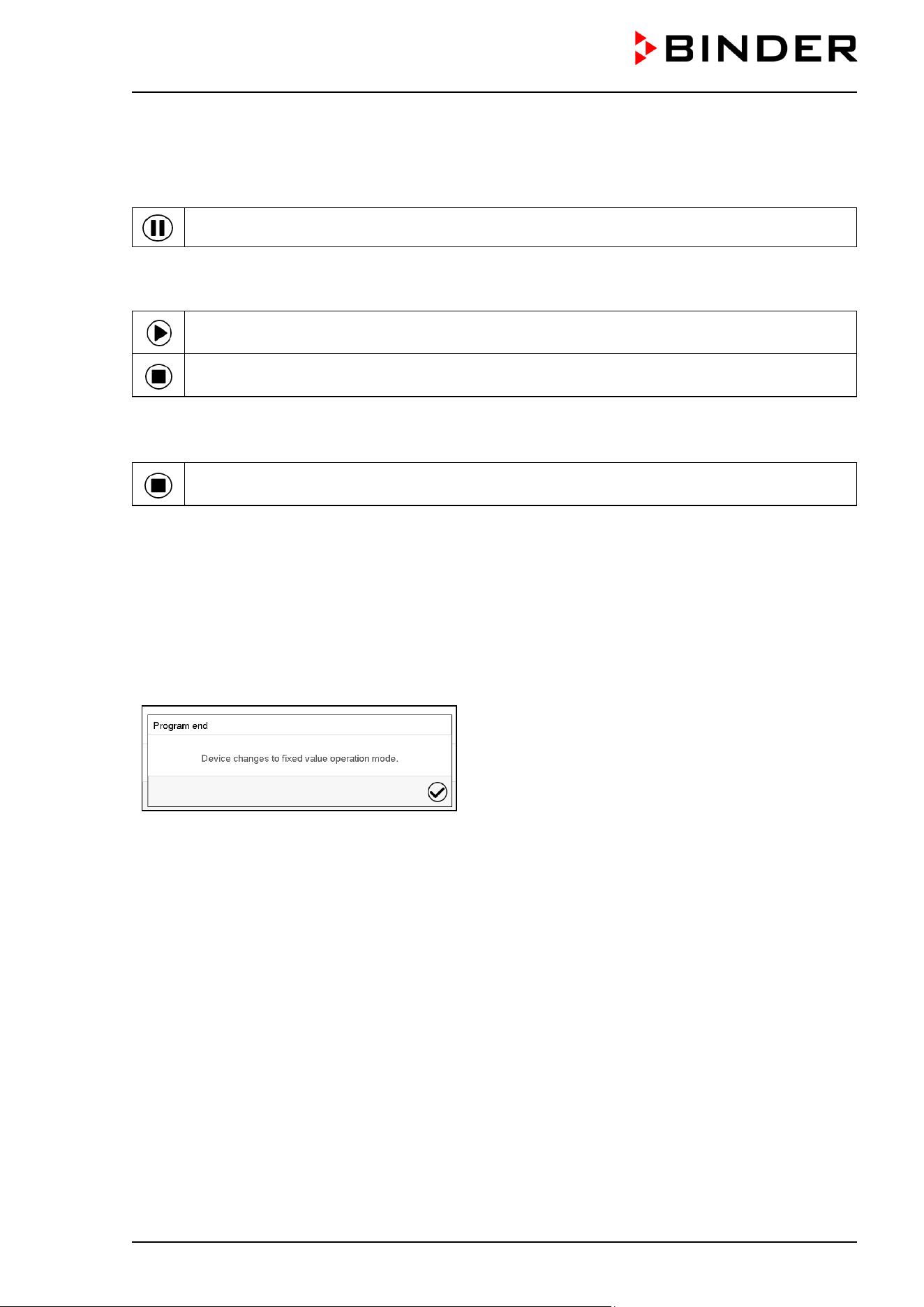
CB / CB-UL, CBF / CBF-UL (E7) 07/2022 Page 78/199
8.2 Stopping a running timer program
8.2.1 Pausing a running timer program
Press the Program pause icon to interrupt the program.
The program is paused. The program runtime stops running down, the time display flashes.
There are the following options:
Press the Program start icon to continue the program
Press the Cancelling icon to cancel the program
8.2.2 Cancelling a running timer program
Press the Program cancelling icon to cancel the program.
A confirmation prompt is displayed. Press the Confirm icon to confirm that the program shall really be
cancelled.
After confirming the message the controller changes to Fixed value operation mode. The chamber will then
equilibrate to the setpoints of Fixed value operation mode.
8.3 Performance after the end of the program
After the end of the program the message “Device
changes to fixed value operation mode” appears on
the screen.
Press the Confirm icon.
After confirming the message the controller changes to Fixed value operation mode. Temperature and
humidity will then equilibrate to the setpoints of Fixed value operation mode.
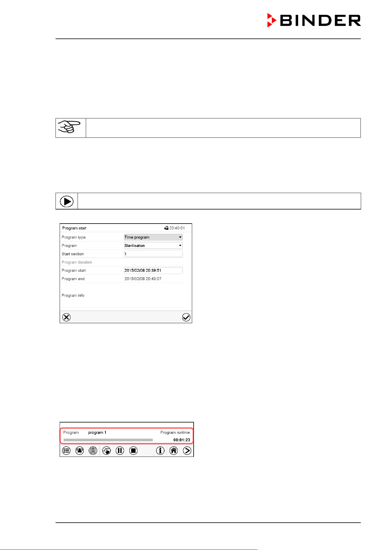
CB / CB-UL, CBF / CBF-UL (E7) 07/2022 Page 79/199
9. Time programs
The MB2 program controller permits programming time programs with real-time reference. It offers 25
program memory positions with up to 100 program sections each.
For each program section you can enter set-points for temperature, CO
2
, O
2
(chamber with O
2
control), and
humidity (CBF / CBF-UL), section duration, type of set-point transition (ramp or step) and the tolerance
ranges.
If the safety controller has been set to “limit” mode, check the setting of the safety controller
when changing the temperature set-point, (chap. 12.2).
Programming remains saved in case of a power failure or after turning off the unit.
Path: Main menu > Programs> Time program
9.1 Starting an existing time program
In Normal display press the Program start icon to access the “Program start” menu.
“Program start” menu
• In the field “Program type” select the setting “Time program”.
• In the field “Program” select the desired program.
• Select the field “Program start” and enter the desired program start time in the “Program start” entry
menu. Press the Confirm icon. The program delay time until program start begins.
The program end is adapted automatically depending on the entered program duration.
After completing the settings, press the Confirm icon to take over the entries and exit the menu. The
program starts running.
If instead you press the Close icon to exit the menu without taking over the entries, the program will not
start.
Normal display. Information on the bottom of the
screen indicates the currently running program and the
time already passed. The grey bar shows how much
time of the whole time is elapsed. If program duration
has been set to infinite, the grey bar is not displayed.
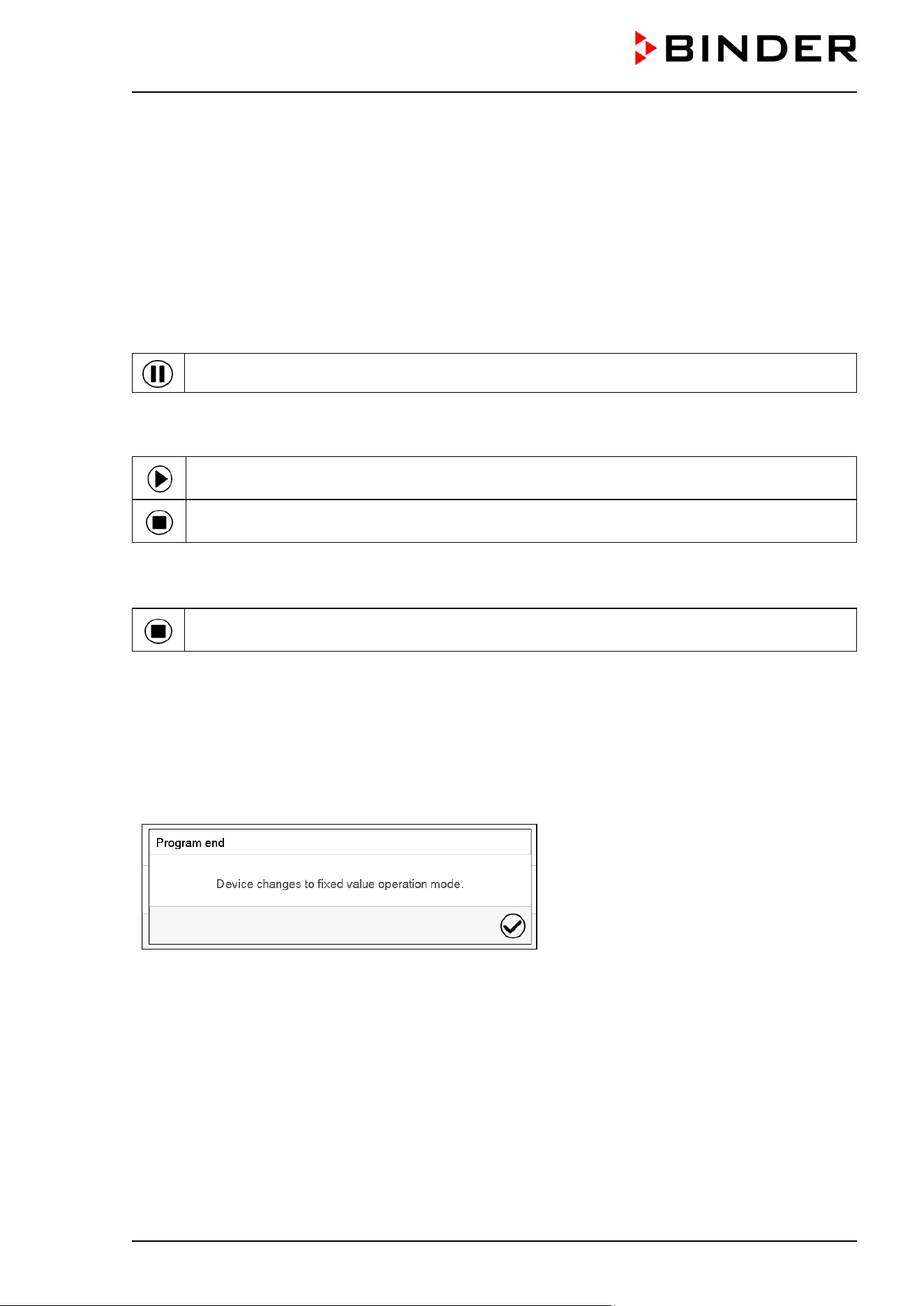
CB / CB-UL, CBF / CBF-UL (E7) 07/2022 Page 80/199
9.1.1 Performance during program delay time
During the configured program delay time until program start, the controller equilibrates to the current
setpoints of Fixed value operation mode. Modifications of these setpoints are effective. When the
configured moment for program start is reached, the program delay time ends and the program starts
running.
9.2 Stopping a running time program
9.2.1 Pausing a running time program
Press the Program pause icon to interrupt the program..
The program is paused. The program runtime stops running down, the time display flashes.
There are the following options:
Press the Program start icon to continue the program
Press the Cancelling icon to cancel the program
9.2.2 Cancelling a running time program
Press the Program cancelling icon to cancel the program.
A confirmation prompt is displayed. Press the Confirm icon to confirm that the program shall really be
cancelled.
After confirming the message, the controller changes to Fixed value operation mode. Temperature and
humidity will then equilibrate to the setpoints of Fixed value operation mode.
9.3 Performance after the end of the program
After the end of the program the message
“Device changes to fixed value operation
mode” appears on the screen.
Press the Confirm icon.
As long as the message has not been confirmed, the setpoint of the last program section remains effective.
Program the last section as desired. If the heating, CO
2
control, O
2
control (chamber with O
2
control) and
humidification (CBF / CBF-UL) shall turn off, activate operation line “Idle mode” in the last program section.
After confirming the message the controller changes to Fixed value operation mode. The setpoints of Fixed
value operation mode are then equilibrated.
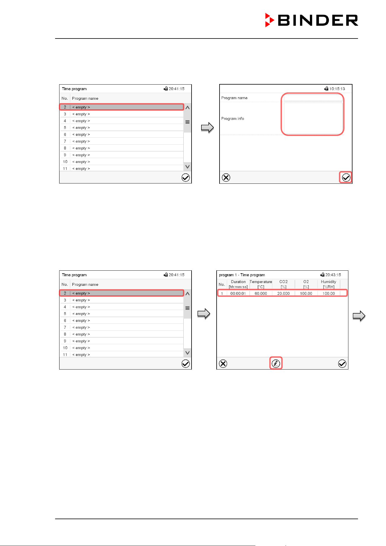
CB / CB-UL, CBF / CBF-UL (E7) 07/2022 Page 81/199
9.4 Creating a new time program
Path: Main menu > Programs > Time program
“Time program” menu:
overview of the existing programs.
Select an empty program place.
Enter the program name and, if desired,
additional program information in the
corresponding fields.
Press the Confirm icon.
The program view opens (chap. 9.5).
9.5 Program editor: program management
Path: Main menu > Programs > Time program
“Time program” menu:
overview of the existing programs.
Select an existing program (example: program
3) or create a new program (chap. 9.4).
The program view opens.
Program view (example: program 1).
If a new program has been created, there is
just one program section.
There are the following options:
Select a program section to open the
section editor (chap. 9.6)
Press the Edit icon to open the program
editor
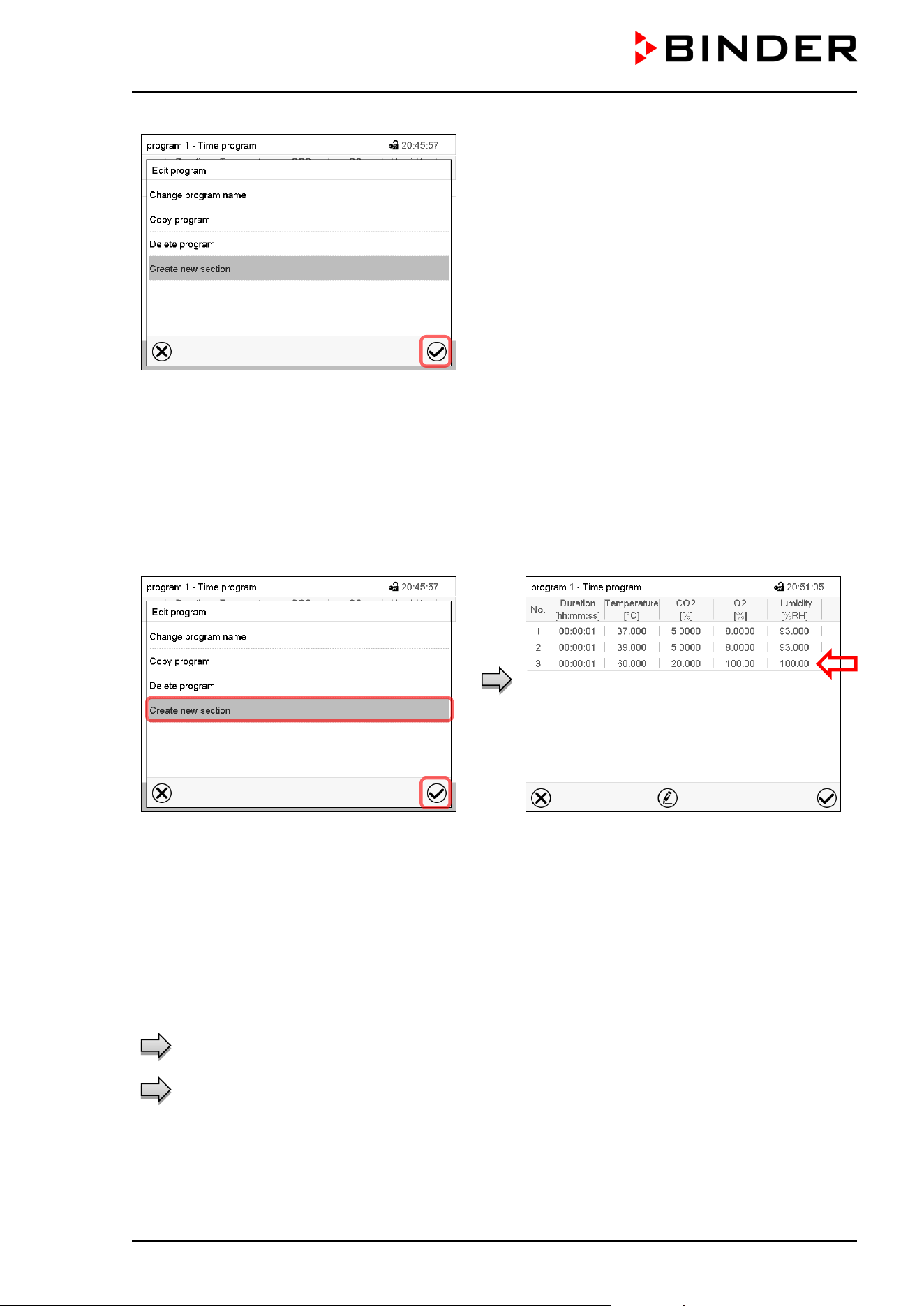
CB / CB-UL, CBF / CBF-UL (E7) 07/2022 Page 82/199
Program editor: “Edit program” menu
Select the desired function and press the Confirm
icon.
The program editor offers following options:
• Change the program name
• Copy program
• Replace program: Replacing an new or an existing program with the copied program. This menu point
is visible only after a program has been copied.
• Delete program
• Create new section
To add a new section, select “Create new
section” and press the Confirm icon.
The program view opens.
Program view.
A new section is always added at the very
bottom (example: section 3).
9.5.1 Deleting a time program
Path: Main menu > Programs > Time program
In the “Time program” menu select the program to be deleted. The program view opens.
In the program view press the Edit icon to open the program editor
In the program editor select “Delete program” and press the Confirm icon.
The program is deleted. The controller returns to the program view.
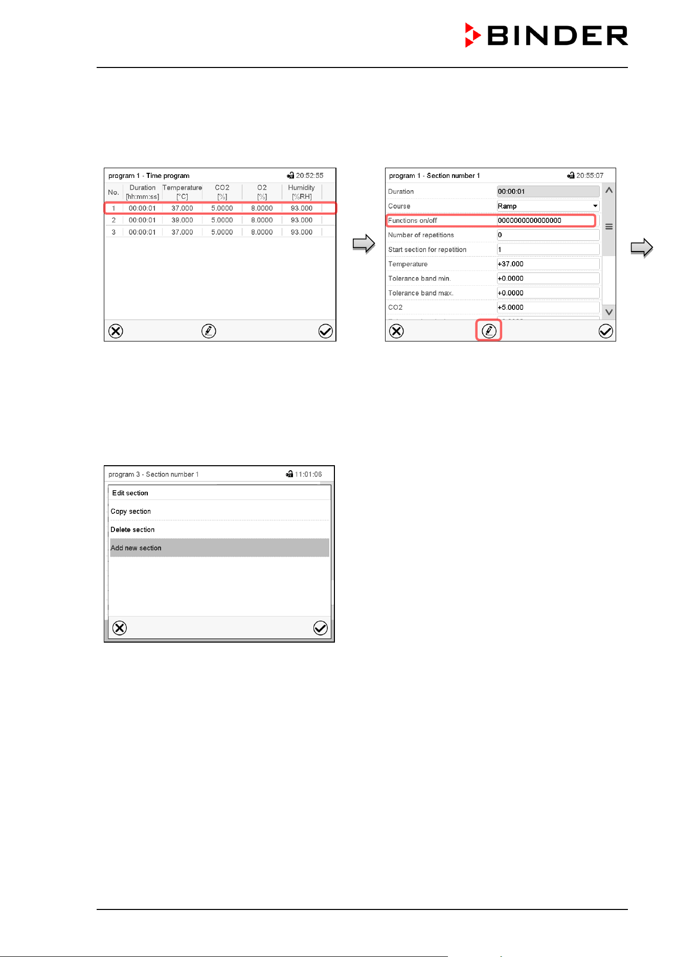
CB / CB-UL, CBF / CBF-UL (E7) 07/2022 Page 83/199
9.6 Section editor: section management
Path: Main menu > Programs > Time program
Select the desired program.
Program view.
Select the desired program section
(example: section 1)
Section view (example: section 1).
There are the following options:
Select a parameter to enter or modify the
according value (chap.
9.7)
Press the Edit icon to open the program
editor
Section editor: “Edit section” menu
Select the desired function and press the Confirm icon.
The section editor offers following options:
• Copy section
• Replace section: Replacing an existing section with the copied section. This menu point is visible only
after a section has been copied.
• Insert section: Adding the copied section. This menu point is visible only after a section has been copied.
• Delete section
• Add new section
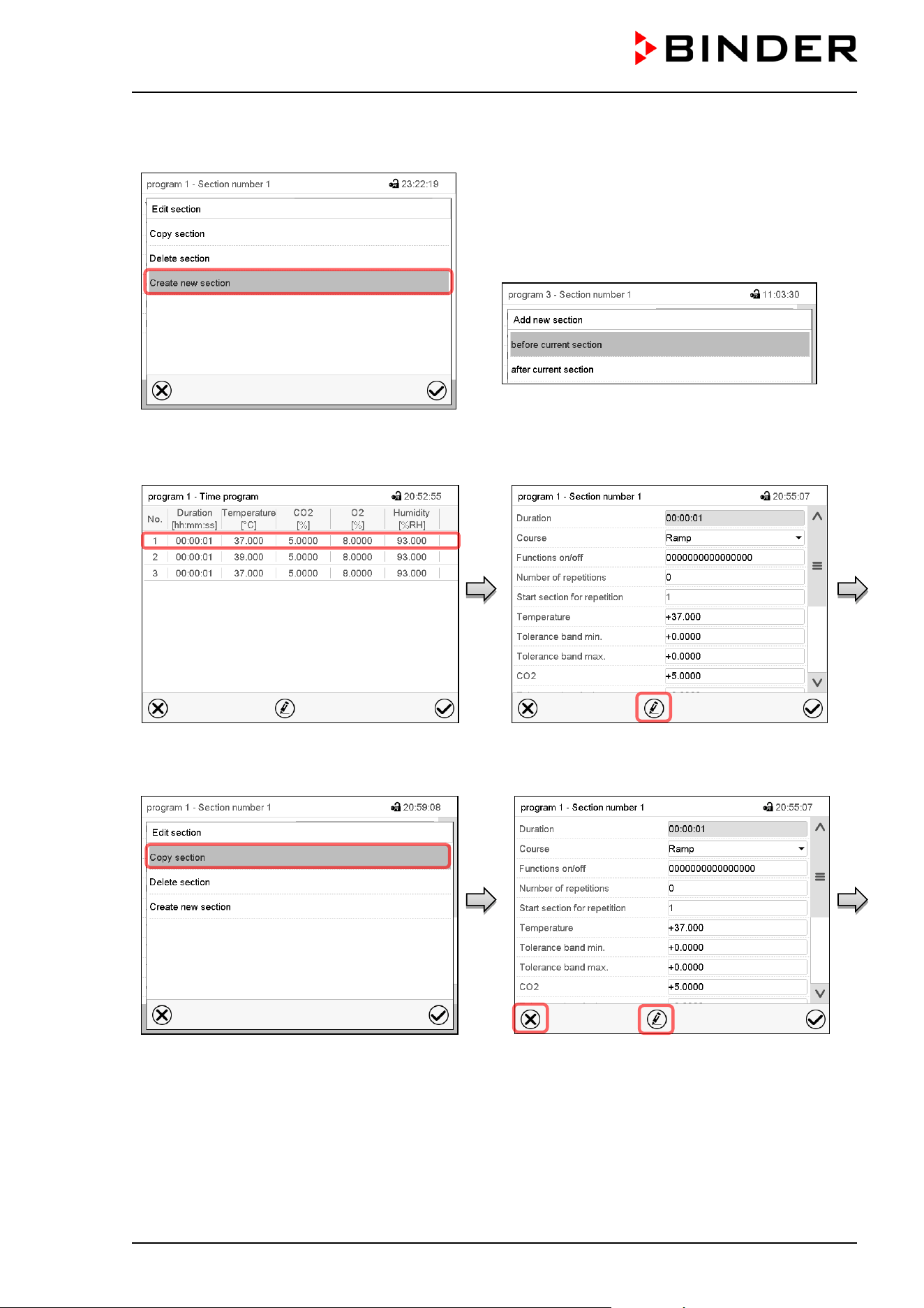
CB / CB-UL, CBF / CBF-UL (E7) 07/2022 Page 84/199
9.6.1 Add a new program section
Section editor: “Edit section” menu.
Select “Create new section” and press the
Confirm icon.
Then select whether to insert the new section
before or after the current section.
Press the Confirm icon. The new section opens.
9.6.2 Copy and insert or replace a program section
Program view.
Select the program section to be copied
(example: section 1)
Section view (example: section 1).
Press the Edit icon to open the section editor.
Section editor: “Edit section” menu
Select “Copy section” and press the Confirm
icon.
The current section (example: section 1) is
copied.
The controller returns to the section view.
Section view (example: section 1).
Press the Close icon to change to the
program view, if you want to select another
section to be replaced or before or after
which the copied section shall be inserted…
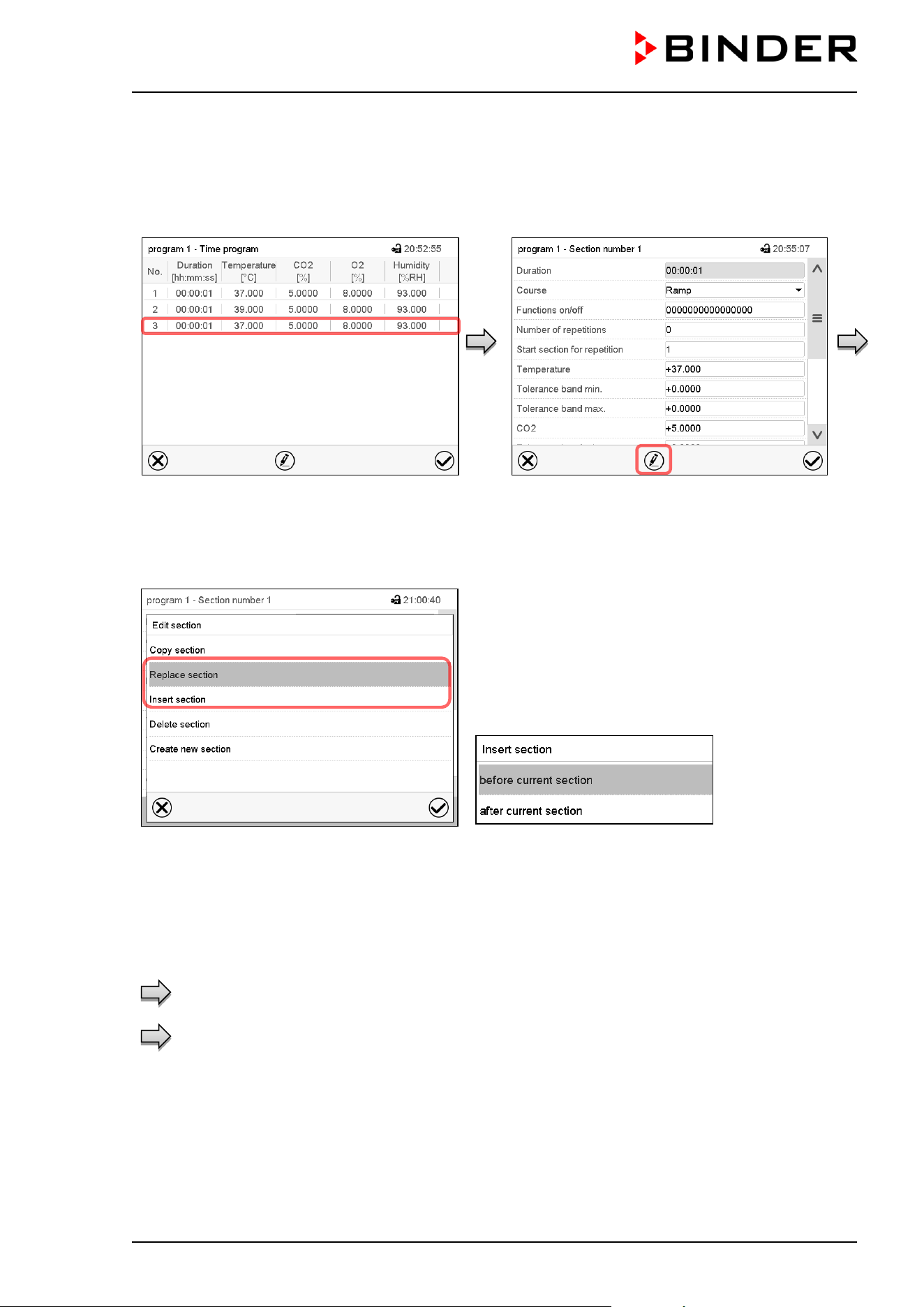
CB / CB-UL, CBF / CBF-UL (E7) 07/2022 Page 85/199
or
Press the Edit icon to open the section editor
if you want the current section to be replaced
or the copied section to be inserted before or
after it
Program view.
Select the section to be replaced or before or
after which the copied section shall be
inserted (example: section 3) and press the
Confirm icon.
Section view (example: section 1).
Press the Edit icon to open the section editor
Section editor: “Edit section” menu
Select “Replace section” to replace the selected section
with the copied section
or
Select “Insert section” to additionally add the copied
section.
In this case select whether to insert it before or after the
selected section.
Press the Confirm icon
9.6.3 Deleting a program section
In the program view select the program section to be deleted. The section view opens.
In the section view press the Edit icon to open the section editor
In the section editor select “Delete section” and press the Confirm icon.
The section is deleted. The controller returns to the section view.
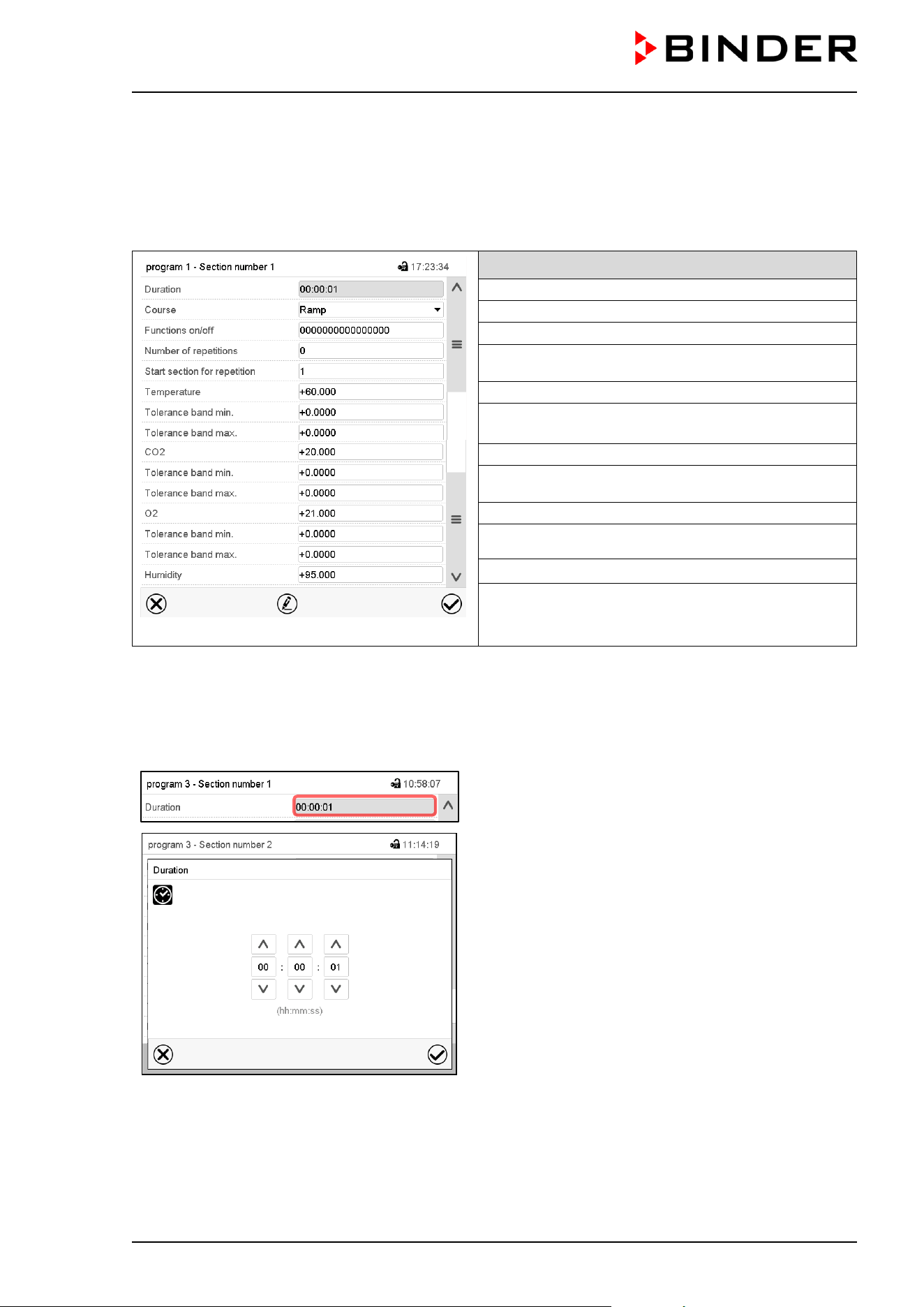
CB / CB-UL, CBF / CBF-UL (E7) 07/2022 Page 86/199
9.7 Value entry for a program section
Path: Main menu > Programs > Time program
Select the desired program and section.
The section view gives access to all parameters of a program section. You can enter or modify the values.
Program name and section number
Section duration
Type of setpoint transition: ramp or step
Operation lines
Repeating one or several sections within a program
Temperature setpoint
Temperature tolerance range: minimum and
maximum
CO
2
setpoint
CO
2
tolerance range: minimum and maximum
O
2
setpoint (chamber with O
2
control)
O
2
tolerance range: minimum and maximum
Humidity setpoint (CBF / CBF-UL)
The setting and control ranges for the individual parameters are the same as for “Fixed value” operating
mode (chap. 7).
9.7.1 Section duration
Section view (partial view).
Select the field “Duration” indicating the time.
“Duration” entry menu.
Enter the desired section duration with the arrow keys
and press the Confirm icon.
Setting range: 0 up to 99 hours 59 min 59 sec.

CB / CB-UL, CBF / CBF-UL (E7) 07/2022 Page 87/199
9.7.2 Set-point ramp and set-point step
You can define the type of transitions for temperature, CO
2
concentration, O
2
concentration (chamber with
O
2
control) and humidity (CBF / CBF-UL) for each individual program section.
“Ramp” mode: Gradual set-points changes
The set-point of a given program section functions as the section’s start value. During the section’s duration,
each set-point gradually passes to the set-point of the subsequent program section. The actual value
follows the continually changing set-point.
If the last program section is in “ramp” mode and the setpoint shall change within this section, then you
must program an additional section (with the shortest possible section duration) to provide the target value
of the last program section. Otherwise, the setpoint would remain constant during the section’s duration.
Programming in the “ramp” mode allows all kinds of temperature and CO
2
/ O
2
and humidity transitions:
• Gradual changes of temperature and CO
2
/ O
2
concentration and humidity
The setpoint changes its value gradually during the entered section duration. The actual value follows
the continually moving set-point at any time.
• Program sections with constant temperature and CO
2
/ O
2
concentration and humidity
The setpoints (initial values) of two subsequent program sections are identical; so the temperature and
humidity remain constant during the entire duration of the first program section.
• Sudden changes of temperature and CO
2
/ O
2
concentration and humidity
Steps can be programmed in ramp mode as temperature / CO
2
/ O
2
/ humidity changes (ramps) that
occur during a very short interval. If the duration of this transitional program section is very short
(minimum entry 1 sec), the temperature, CO
2
/ O
2
or humidity change will proceed rapidly within the
minimum amount of time.
“Step” mode: Sudden set-points changes
The set-point of any program section functions as the section’s target value. At the start of the program
section, heating up, attaining the set gas concentration and humidification occur with the maximum speed
to reach the set-point values and then remain constant for the remaining section time. Therefore the set-
points remain constant for the section’s duration. These changes occur rapidly within the minimum amount
of time (minimum entry: 1 second).
Programming in the “step” mode allows only two kinds of temperature / CO
2
/ O
2
/ humidity transitions:
• Programming gradual changes of temperature / CO
2
/ O
2
/ humidity (ramps) is impossible in the “step”
mode
• Program sections with constant temperature and CO
2
/ O
2
concentration and humidity
The setpoints (target values) of two subsequent program sections are identical; so the temperature /
CO
2
/ O
2
/ humidity remain constant during the entire duration of the first program section.
• Sudden changes of temperature and CO
2
/ O
2
concentration and humidity
The entered setpoint of the section is reached as fast as possible and then held constant for the
remaining section duration.
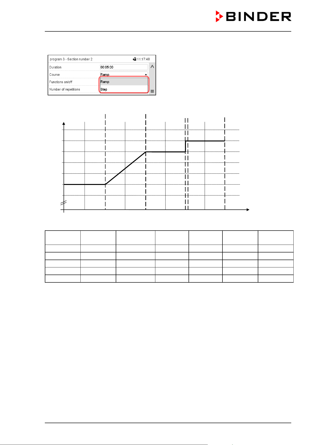
CB / CB-UL, CBF / CBF-UL (E7) 07/2022 Page 88/199
Selecting the setting “Ramp” or “Step”
Section view (partial view).
In the field “Course” select the desired setting
“Ramp” or “Step”.
“Ramp” and “Step” mode example (representation of a temperature course)
W/°C
t/min.
0
38.0
38.5
39.0
39.5
40.0
30 60 90 120 150 180 210 240
37.0
37.5
------------
1-------------------------
2------------------------3------------4----------5------------
Corresponding program table
Section No.
Duration
[hh:mm:ss]
Temperature
[°C]
CO2
[Vol.-%]
O2
[Vol.-%]
Humidity
[% rH]
Ramp or
Step
1
01:00:00
37.5
xxxx
xxxx
xxxx
Step
2
01:00:00
37.5
xxxx
xxxx
xxxx
Ramp
3
01:00:00
39.0
xxxx
xxxx
xxxx
Step
4
00:00:10
39.5
xxxx
xxxx
xxxx
Step
5
01:00:00
39.5
xxxx
xxxx
xxxx
Step
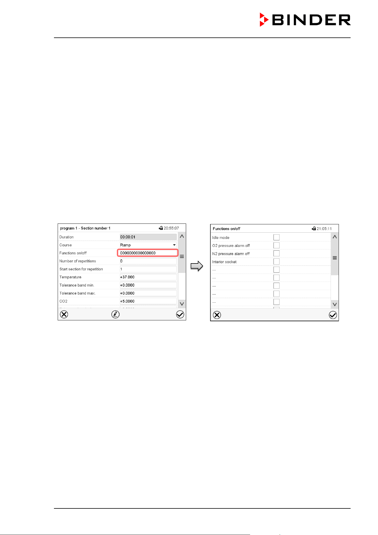
CB / CB-UL, CBF / CBF-UL (E7) 07/2022 Page 89/199
9.7.3 Special controller functions via operation lines
You can define the switching state of up to 16 operation lines (control contacts). They are used to activate
/ deactivate special controller functions.
Chamber with O
2
control: Depending on the required range of O
2
concentration, the type of gas which is
required may vary (chap. 6.6). Therefore, the pressure alarms for O
2
and N
2
can be deactivated individually
with active O
2
control.
For chambers equipped with the optional interior socket (chap. 18.4) you can turn on and off the voltage of
the interior socket via the controller.
• Operation line “Idle mode” activates / deactivates the operating mode “Idle mode”.
• Operation line “O2 pressure alarm off” activates / deactivates the O
2
pressure alarm (chamber with O
2
control and optional alternative control range)
• Operation line “N2 pressure alarm off” activates / deactivates the N
2
pressure alarm (chamber with O
2
control)
• Operation line “Interior socket” activates / deactivates interior socket (option, available via BINDER
INDIVIDUAL Customized Solutions)
The other operation lines are without function.
Use the Section editor to configure the operation lines.
Section view.
Select the field “Functions on/off”.
“Functions on/off” entry menu (view with chamber
with O
2
control with optional interior socket).
Mark / unmark the checkbox of the desired
function to activate / deactivate it and press the
Confirm icon.
The controller returns to the section view.
Activated operation line: switching status “1” (On)
Deactivated operation line: switching status “0” (Off)
The operation lines count from right to left.
Example:
Activated operation line “Idle mode” = 000000000000000
1
Deactivated operation line “Idle mode” = 000000000000000
0
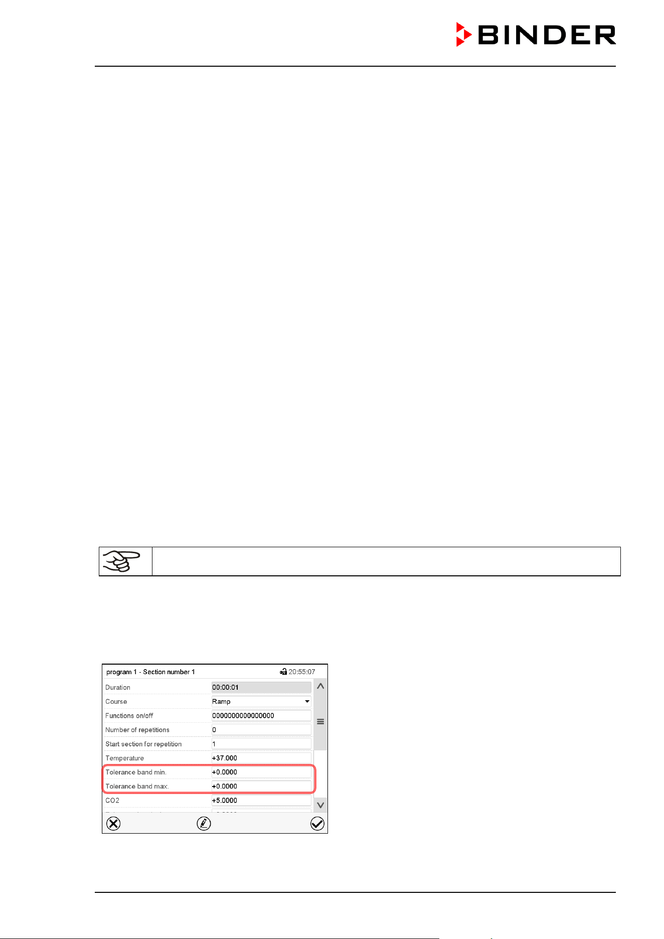
CB / CB-UL, CBF / CBF-UL (E7) 07/2022 Page 90/199
9.7.4 Setpoint entry
• Select the field “Temperature” and enter the desired temperature setpoint.
Setting range: 20 °C up to 60 °C.
Confirm entry with Confirm icon. The controller returns to the section view.
• Select the field “CO2” and enter the desired CO
2
setpoint.
Setting range: 0 vol.-% up to 20 vol.-%.
Confirm entry with Confirm icon. The controller returns to the section view.
Chamber with O
2
control:
• Select the field “O2” and enter the desired O
2
setpoint.
Setting range with regular hypoxic control range: 0.2 vol.-% up to 20 vol.-%.
Setting range with alternative control range: 5 vol.-% up to 95 vol.-%.
Confirm entry with Confirm icon. The controller returns to the section view.
CBF / CBF-UL:
• Select the field “Humidity” and enter the desired humidity setpoint.
Setting range: 50 % r.h. up to 95 % r.h.
Confirm entry with Confirm icon. The controller returns to the section view.
9.7.5 Tolerance range
You can specify tolerance ranges for temperature, CO
2
and O
2
(chamber with O
2
control) and humidity
(CBF / CBF-UL) for each program section with different values for the tolerance minimum and maximum.
When the actual value exceeds the given threshold, the program is interrupted. This is indicated on the
display (see below). When the actual temperature is situated again within the entered tolerance limits, the
program automatically continues. Therefore, the duration of the program may be extended due to the
programming of tolerances.
Programming of tolerances may extend program duration.
An entry of “-99999” for the tolerance minimum means “minus infinite” and an entry of “999999” for the
tolerance maximum means “plus infinite”. Entry of these values will never lead to program interruption. The
entry of “0” for the tolerance minimum and/or maximum deactivates the respective tolerance function.
When requesting rapid value transitions, we recommend not programming tolerance values in order to
enable the maximum speed for heating-up and CO
2
/ O
2
control, and humidification.
Section view, showing the temperature tolerance
band
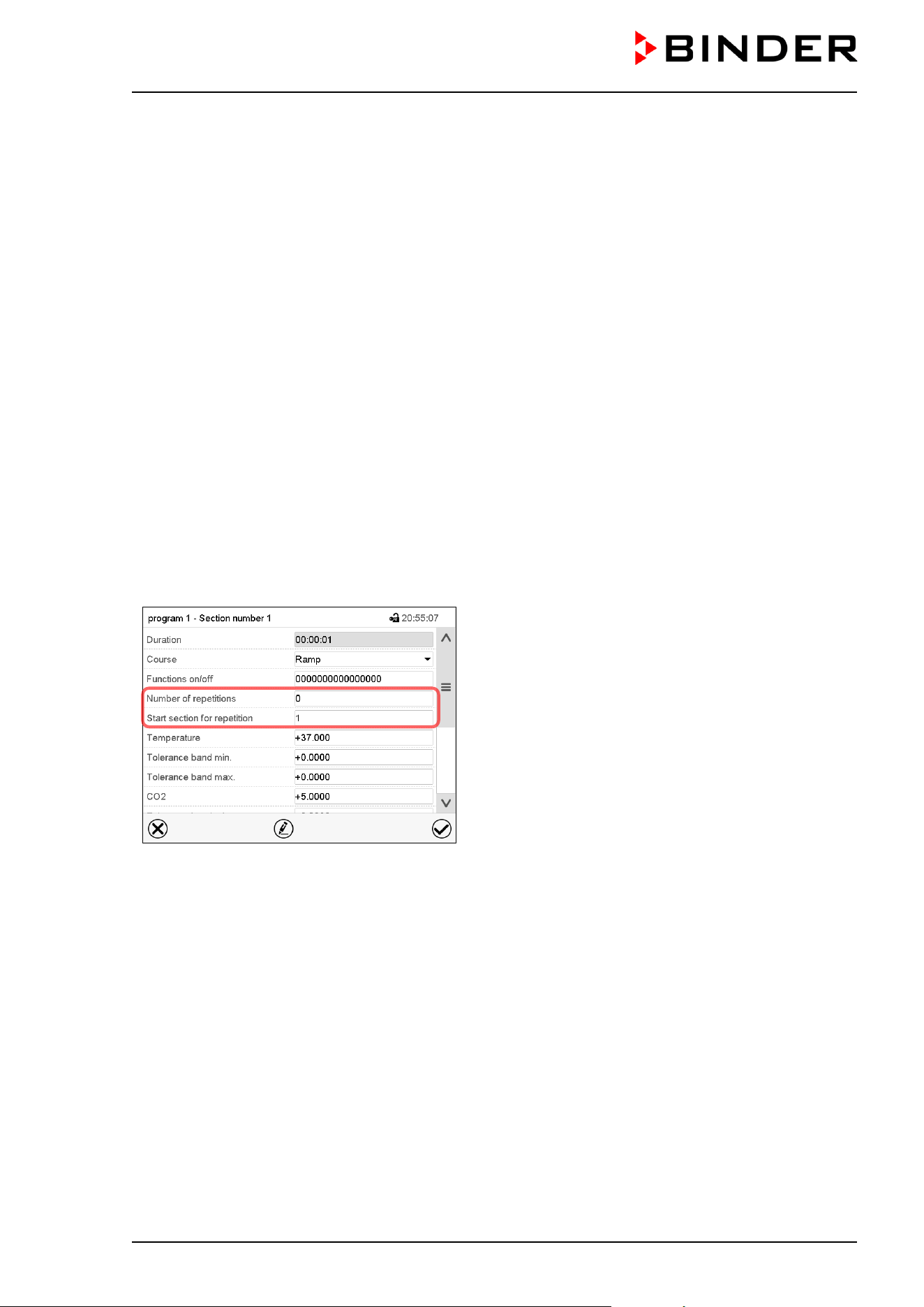
CB / CB-UL, CBF / CBF-UL (E7) 07/2022 Page 91/199
• Select the field “Tolerance band min” and enter the desired lower tolerance band value. Setting range:
-99999 to 99999. Confirm entry with Confirm icon. The controller returns to the section view.
• Select the field “Tolerance band max” and enter the desired upper tolerance band value. Setting range:
-99999 to 99999. Confirm entry with Confirm icon. The controller returns to the section view.
Set the tolerance ranges for other parameters accordingly, if desired.
If one of the actual values (temperature, CO
2
, O
2
, humidity) is outside the program tolerance range the
whole program course is interrupted. During this program interruption time the controller equilibrates to the
set-points of the current section.
The screen header indicates “Program pause (tolerance band)”. The program runtime indication flashes
and does not proceed any further.
When the temperature or CO
2
/ O
2
or humidity values are back within the entered program tolerance range,
the program continues automatically.
9.7.6 Repeating one or several sections within a time program
You can repeat several subsequent sections together. It is not possible to define the start section the same
time also as the target section, therefore you cannot repeat a single individual section.
Enter the desired number of repetitions in the field „Number of repetitions“ and the number of the section
to start the repetition cycle with in the field “Start section for repetition” To have sections repeated infinitely,
enter the number of repetitions as “-1”.
The selected sections are repeated as many times as selected. Then the program continues.
Section view, showing the repetition function
• Select the field “Number of repetitions” and enter the desired number of repetitions. Setting range: 1 to
99, and -1 for infinite. Confirm entry with Confirm icon. The controller returns to the section view.
• Select the field “Start section for repetition” and enter the section number, at which the repetition should
start. Setting range: 1 up to the section before the currently selected section. Confirm entry with Confirm
icon. The controller returns to the section view.
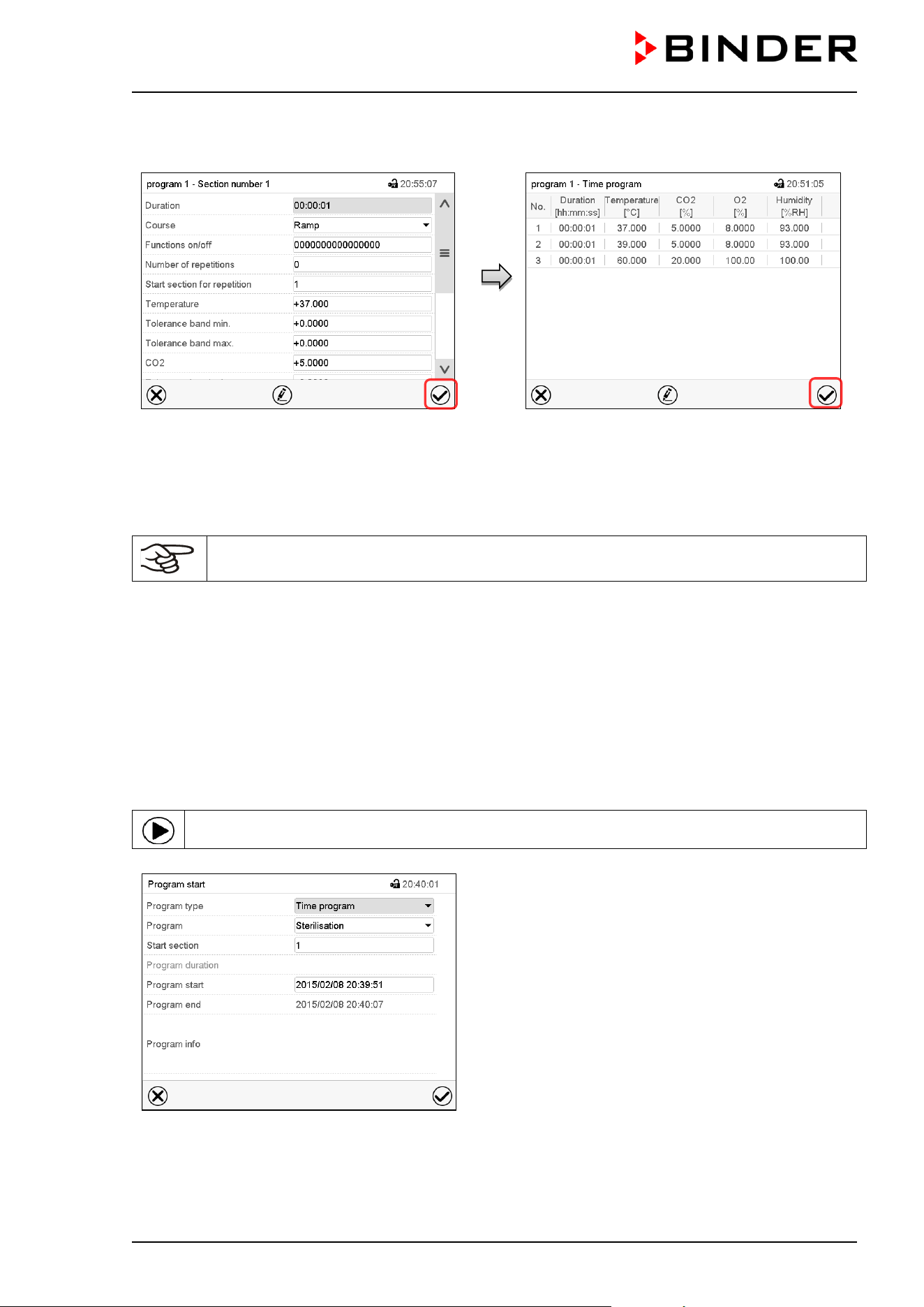
CB / CB-UL, CBF / CBF-UL (E7) 07/2022 Page 92/199
9.7.7 Saving the time program
Section view.
After the all desired values of the program
section have been configured, press the
Confirm icon to take over the programming.
The controller changes to the program view.
Program view.
Press the Confirm icon to take over the
programming.
The controller changes to the Normal display.
To save the programming it is absolutely required to press the Confirm icon. Otherwise all
settings will be lost! There is no confirmation prompt!
10. Week programs
The MB2 program controller permits programming week programs with real-time reference. It offers 5 week
program places in total with up to 100 shift points for each week program.
Path: Main menu > Programs> Week program
10.1 Starting an existing week program
In Normal display press the Program start icon to access the “Program start” menu.
“Program start” menu.
• In the field “Program type” select the setting “Week program”.
• In the field “Program” select the desired program.
• There are no further settings available in the “Program start” menu for week programs, as they are
needed only for time programs.
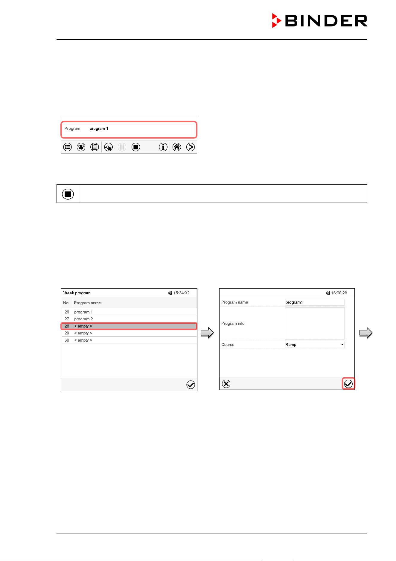
CB / CB-UL, CBF / CBF-UL (E7) 07/2022 Page 93/199
After completing the settings, press the Confirm icon to take over the entries and exit the menu. The
program starts running.
If instead you press the Close icon to exit the menu without taking over the entries, the program will not
start.
After starting the week program, the previously entered week program setpoints are active and will be
equilibrated according to the current time.
Information on the bottom of the screen indicates the
currently running program.
10.2 Cancelling a running week program
Press the Program cancelling icon to cancel the program.
A confirmation prompt is displayed. Press the Confirm icon to confirm that the program shall really be
cancelled.
After confirming the message the controller changes to Fixed value operation mode. The chamber will then
equilibrate to the setpoints of Fixed value operation mode.
10.3 Creating a new week program
Path: Main menu > Programs > Week program
“Week program” menu:
overview of the existing programs.
Select an empty program place.
Enter the program name and, if desired,
additional program information in the
corresponding fields.
Select the set-point course “Ramp” or “Step”
(chap. 10.6.1).
Press the Confirm icon. The program view
opens.
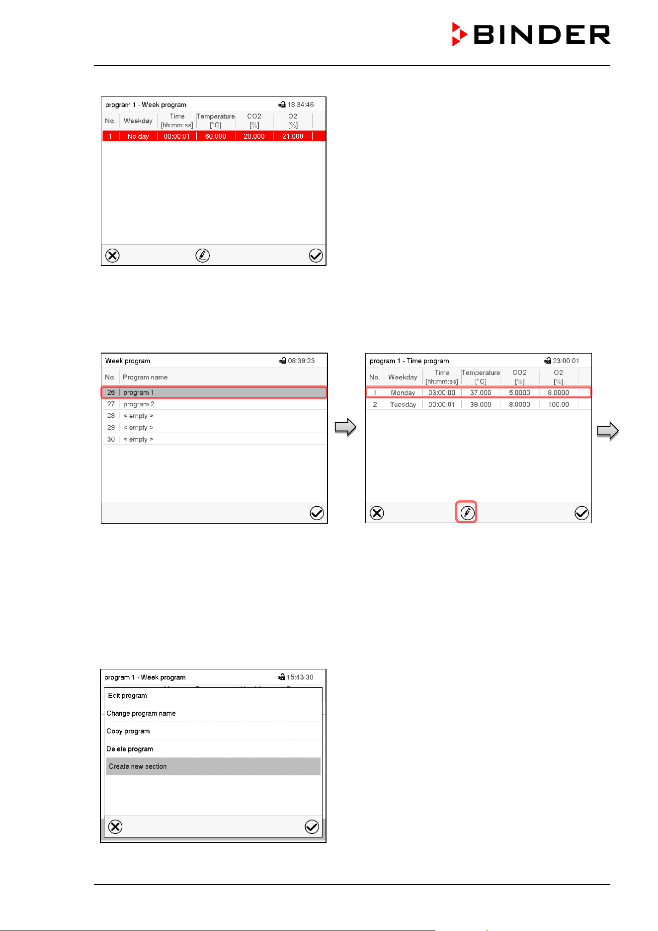
CB / CB-UL, CBF / CBF-UL (E7) 07/2022 Page 94/199
Program view.
For the first section no weekday is specified.
Therefore the section is first marked in red and
cannot be saved.
10.4 Program editor: program management
Path: Main menu > Programs > Week program
“Week program” menu:
overview of the existing programs.
Select an existing program
(example: program 1).
Program view (example: program 1).
If a new program has been created, there is
just one program section.
There are the following options:
Select a program section to open the
section editor (chap. 10.4.1)
Press the Edit icon to open the program
editor
Program editor: “Edit program” menu.
Select the desired function and press the Confirm icon.
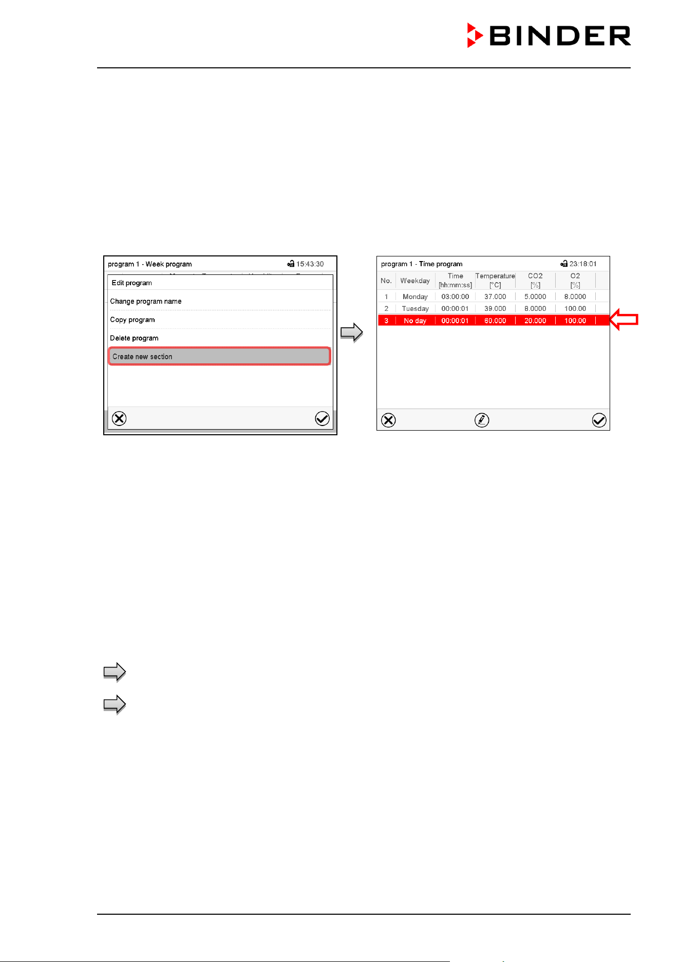
CB / CB-UL, CBF / CBF-UL (E7) 07/2022 Page 95/199
The program editor offers following options:
• Change program name. This menu also offers to configure the ramp / step mode setting (chap. 10.6.1).
• Copy program
• Replace program: Replacing an new or an existing program with the copied program. This menu point
is visible only after a section has been copied.
• Delete program
• Create new section
To add a new section, select “Create new
section” and press the Confirm icon.
The program view opens.
Program view.
With a new section no weekday is specified.
Therefore the section is first marked in red and
cannot be saved.
A new section is always added at the very bottom
(example: section 3). When the section start is
specified the sections are automatically arranged in
the correct chronological order.
10.4.1 Deleting a week program
Path: Main menu > Programs > Week program
In the “Week program” menu select the program to be deleted. The program view opens.
In the program view press the Edit icon to open the program editor
In the program editor select “Delete program” and press the Confirm icon.
The program is deleted. The controller returns to the program view.
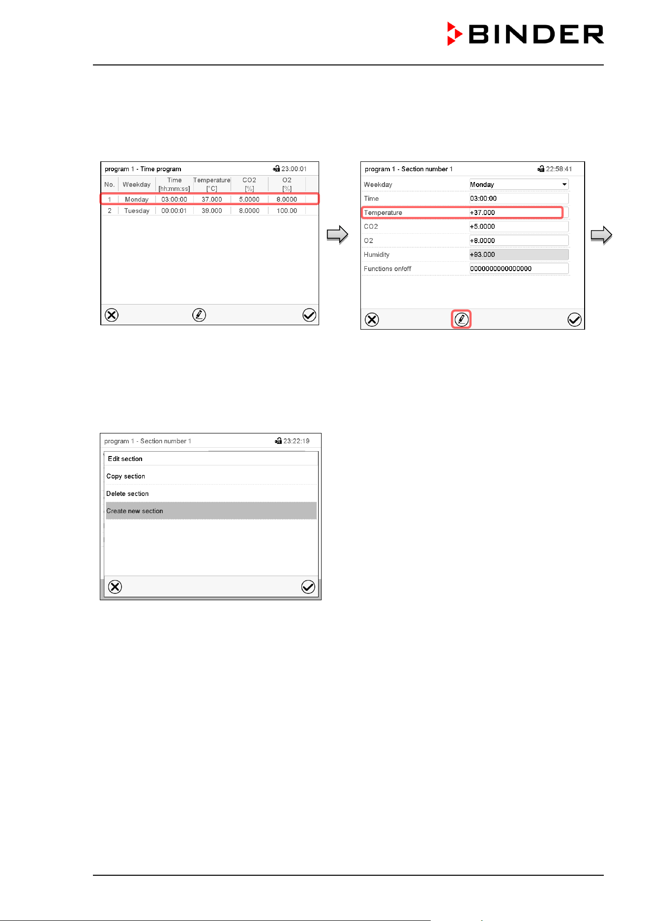
CB / CB-UL, CBF / CBF-UL (E7) 07/2022 Page 96/199
10.5 Section editor: section management
Path: Main menu > Programs > Week program
Select the desired program.
Program view.
Select the desired program section
(example: section 1)
Section view (example: section 1).
There are the following options:
Select a parameter to enter or modify
the according value (chap.
10.6)
Press the Edit icon to open the program
editor
Section editor: “Edit section” menu
Select the desired function and press the Confirm icon.
The section editor offers following options:
• Copy section
• Replace section: Replacing an existing section with the copied section. This menu point is visible only
after a section has been copied.
• Insert section: Adding the copied section. This menu point is visible only after a section has been copied.
• Delete section
• Create new section
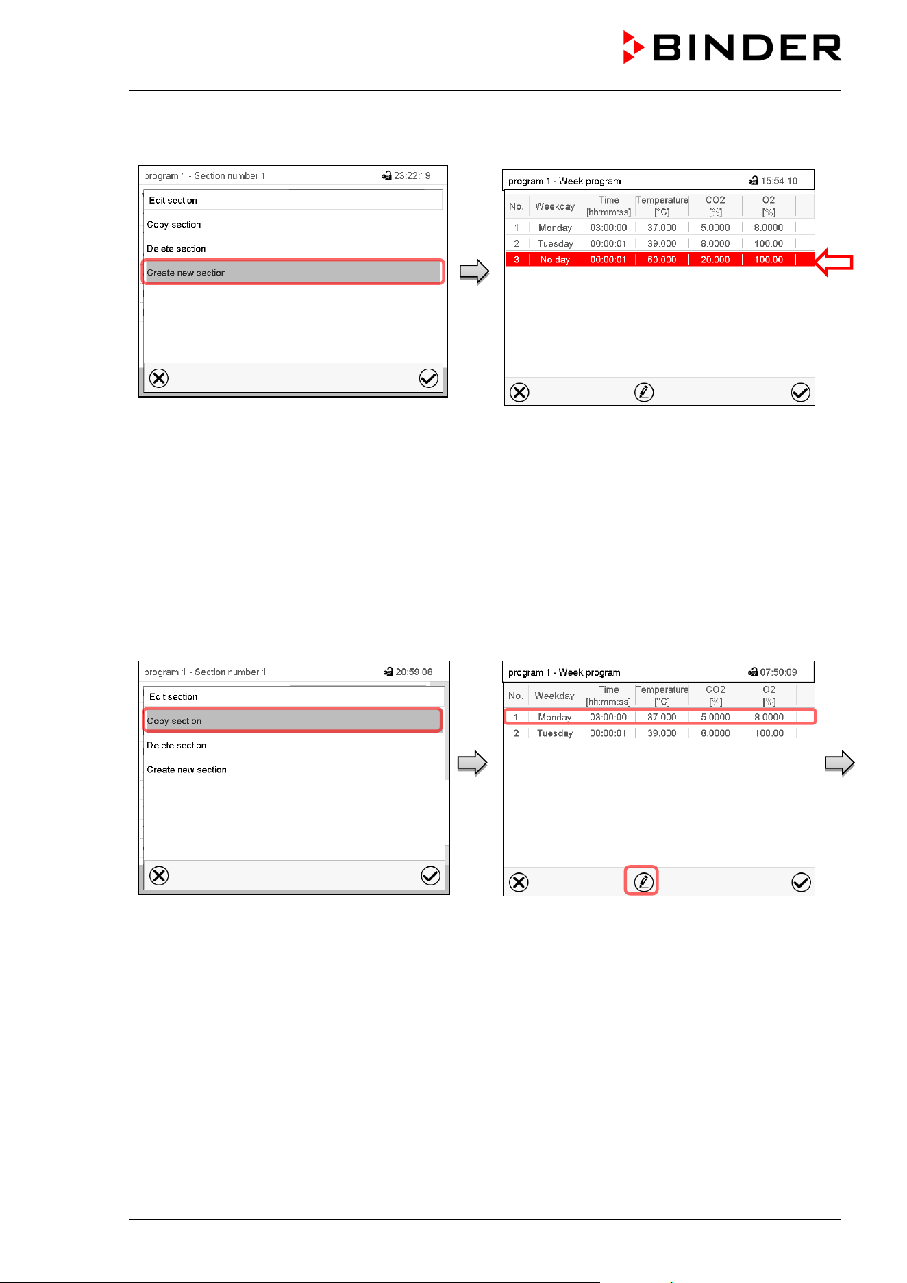
CB / CB-UL, CBF / CBF-UL (E7) 07/2022 Page 97/199
10.5.1 Add a new program section
Section editor: “Edit section” menu.
Select “Create new section” and press the
Confirm icon.
Program view.
With a new section no weekday is specified.
Therefore the section is first marked in red and
cannot be saved.
A new section is always added at the very bottom
(example: section 3). When the section start is
specified the sections are automatically arranged in
the correct chronological order.
10.5.2 Copy and insert or replace a program section
Section editor: “Edit section” menu
Select “Copy section” and press the Confirm
icon.
The current section (example: section 1) is
copied.
The controller returns to the program view.
Program view
Select the section to be replaced or before or
after which the copied section shall be
inserted (example: section 1).
Press the Confirm icon
The controller returns to the section editor

CB / CB-UL, CBF / CBF-UL (E7) 07/2022 Page 98/199
Section editor: “Edit section” menu
Select “Replace section” to replace the selected
section with the copied section
or
Select “Insert section” to additionally add the copied
section.
Press the Confirm icon.
If you selected “Insert section” the sections are
automatically arranged in the correct chronological
order.
10.5.3 Deleting a program section
In the program view select the program section to be deleted. The section view opens.
In the section view press the Edit icon to open the section editor
In the section editor select “Delete section” and press the Confirm icon.
The section is deleted. The controller returns to the section view.
10.6 Value entry for a program section
Path: Main menu > Programs > Week program
Select the desired program and section.
The setting and control ranges for the individual parameters are the same as for “Fixed value” operating
mode (chap. 7).
10.6.1 Set-point ramp and set-point step modes
The explanation of the settings “Ramp” or “Step” is given in chap. 9.7.2.
You can define the type of transitions for temperature, CO
2
concentration, O
2
concentration (chamber with
O
2
control) and humidity (CBF / CBF-UL) for the entire week program.
Select the desired program and press the Edit icon to open the program editor. In the program editor select
the “Change program name” function and press the Confirm icon.
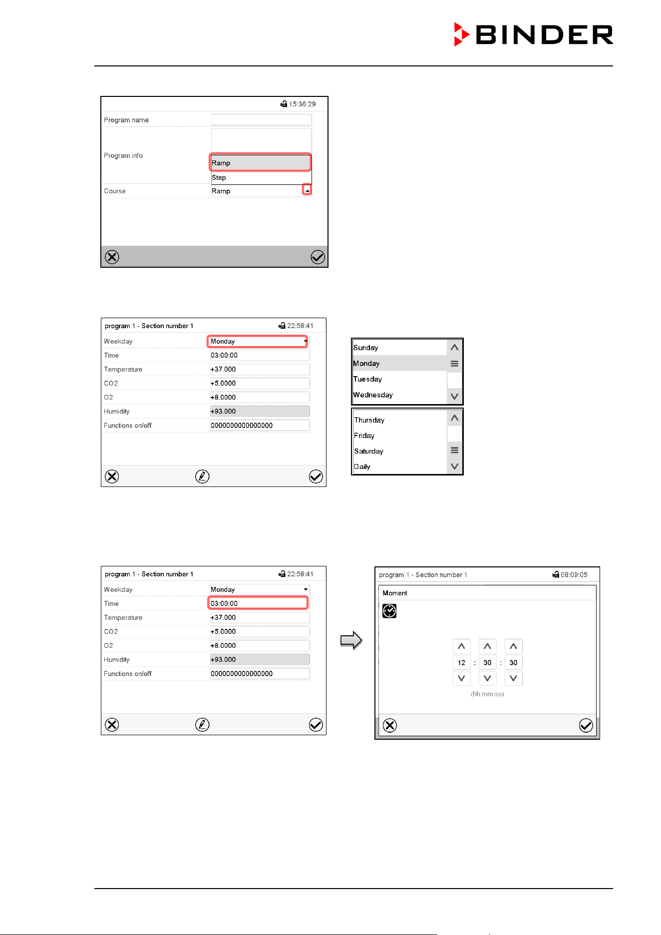
CB / CB-UL, CBF / CBF-UL (E7) 07/2022 Page 99/199
“Change program name” menu.
In the field “Course” select the desired setting
“Ramp” or “Step” and press the Confirm icon.
10.6.2 Weekday
Section view.
In the field “Weekday” select the desired weekday.
With “Daily” selected, this section will run every day
at the same time.
10.6.3 Start time
Section view.
Select the field “Moment”.
Entry menu “Moment”.
Select with the arrow keys the desired start
moment of the section and press the Confirm
icon.

CB / CB-UL, CBF / CBF-UL (E7) 07/2022 Page 100/199
10.6.4 Setpoint entry
• Select the field “Temperature” and enter the desired temperature setpoint.
Setting range: 20 °C up to 60 °C.
Confirm entry with Confirm icon. The controller returns to the section view.
• Select the field “CO2” and enter the desired CO
2
setpoint.
Setting range: 0 vol.-% up to 20 vol.-%.
Confirm entry with Confirm icon. The controller returns to the section view.
Chamber with O
2
control:
• Select the field “O2” and enter the desired O
2
setpoint.
Setting range with regular hypoxic control range: 0.2 vol.-% up to 20 vol.-%.
Setting range with alternative control range: 5 vol.-% up to 95 vol.-%.
Confirm entry with Confirm icon. The controller returns to the section view.
CBF / CBF-UL:
• Select the field “Humidity” and enter the desired humidity setpoint.
Setting range: 50 % r.h. up to 95 % r.h.
Confirm entry with Confirm icon. The controller returns to the section view.
10.6.5 Special controller functions via operation lines
You can define the switching state of up to 16 operation lines (control contacts). They are used to activate
/ deactivate special controller functions.
Chamber with O
2
control: Depending on the required range of O
2
concentration, the type of gas which is
required may vary (chap. 6.6). Therefore, the pressure alarms for O
2
and N
2
can be deactivated individually
with active O
2
control.
For chambers equipped with the optional interior socket (chap. 18.4) you can turn on and off the voltage of
the interior socket via the controller.
• Operation line “Idle mode” activates / deactivates the operating mode “Idle mode”.
• Operation line “O2 pressure alarm off” activates / deactivates the O
2
pressure alarm (chamber with O
2
control and optional alternative control range)
• Operation line “N2 pressure alarm off” activates / deactivates the N
2
pressure alarm (chamber with O
2
control)
• Operation line “Interior socket” activates / deactivates interior socket (option, available via BINDER
INDIVIDUAL Customized Solutions)
The other operation lines are without function.
Select the desired program and section. You can set the operation lines in the “Functions on/off” field.
For details please refer to chap. 9.7.3.
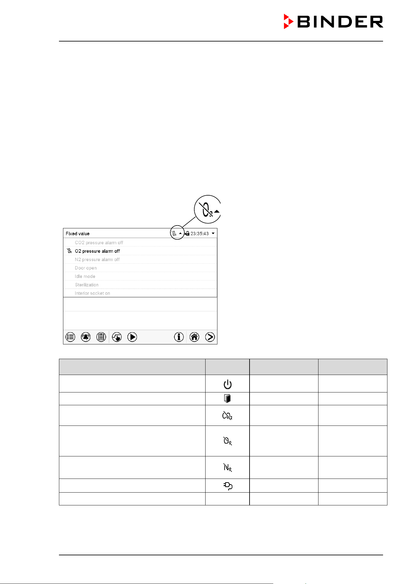
CB / CB-UL, CBF / CBF-UL (E7) 07/2022 Page 101/199
11. Notification and alarm functions
11.1 Notification and alarm messages overview
11.1.1 Notifications
Notifications are indicated by information icons displayed in the screen header in Normal display
An information icon serves as an indication of a certain condition.
If this condition persists, in some cases an alarm will be triggered after a fix or configurable interval. As long
as the condition persists, the information icon therefore continues to be displayed also in state of alarm. If
during alarm the conditions ends, e.g., if during a tolerance range alarm the actual value returns to within
the tolerance range, the information icon disappears, whereas the alarm will continue until manual
acknowledgement.
Press the flash icon next to the information icon to access the corresponding text information.
Normal display showing the text information.
The currently valid information texts are
highlighted in black (example: “O2 pressure
alarm off“)
Condition
Information
icon
Text information
Start after
condition occurred
The controller is in Idle mode (chap. 5.4).
“Idle mode” immediately
Chamber door open
“Door open” immediately
CO
2
pressure alarm deactivated
“CO2 pressure
alarm off”
immediately
Chamber with O
2
control and optional
alternative control range:
O
2
pressure alarm deactivated
“O2 pressure alarm
off”
immediately
Chamber with O
2
control:
N
2
pressure alarm deactivated
“N2 pressure alarm
off”
immediately
Interior socket (option) activated
“Interior socket” immediately
Hot air sterilization running “Sterilization” immediately
Notifications are not shown in the event list.

CB / CB-UL, CBF / CBF-UL (E7) 07/2022 Page 102/199
11.1.2 Alarm messages
Condition Alarm message
Start after
condition occurred
Zero-voltage relay
alarm output
Having reached the setpoint, the
actual temperature value deviates by
more than the set tolerance range
value and longer than the set delay
time from the setpoint
or
the temperature doesn’t reach the
tolerance range within 3 hours from
turning on the chamber or closing the
door.
“Temperature
range”
After configurable
delay time (chap.
11.5). Factory
setting: 10 minutes
With alarm start
Having reached the setpoint, the
actual CO
2
concentration deviates by
more than the set tolerance range
value and longer than the set delay
time from the setpoint
or
the CO
2
concentration doesn’t reach
the tolerance range within 3 hours
from turning on the chamber or closing
the door
“CO2 range”
After configurable
delay time (chap.
11.5). Factory
setting: 10 minutes
With alarm start
Chamber with O
2
control:
Having reached the setpoint, the
actual O
2
concentration deviates by
more than the set tolerance range
value and longer than the set delay
time from the setpoint
or
the O
2
concentration doesn’t reach the
tolerance range within 3 hours from
turning on the chamber or closing the
door
“O2 range”
After configurable
delay time (chap.
11.5). Factory
setting: 10 minutes
With alarm start
CBF / CBF-UL:
Having reached the setpoint, the
actual humidity value deviates by
more than the set tolerance range
value and longer than the set delay
time from the setpoint
or
the humidity doesn’t reach the
tolerance range within 3 hours from
turning on the chamber or closing the
door.
“Humidity range”
After configurable
delay time (chap.
11.5). Factory
setting: 10 minutes
With alarm start
Chamber door is open for longer than
the set delay time.
“Door open”
After configurable
delay time (chap.
11.5). Factory
setting: 1 minute
----
Power failure --- ---- immediately
CB / CB-UL, CBF / CBF-UL (E7) 07/2022 Page 103/199
Condition Alarm message
Start after
condition occurred
Zero-voltage relay
alarm output
Exceeded setpoint of the safety
controller class 3.1
“Safety controller immediately ----
Low CO
2
outlet pressure
(< 0.3 bar / 4.4 psi)
“CO2 pressure” immediately ----
Chamber with O
2
control:
Low O
2
outlet pressure
(< 0.3 bar / 4.4 psi)
“O2 pressure” immediately ----
Chamber with O
2
control:
Low N
2
outlet pressure
(< 0.3 bar / 4.4 psi)
“N2 pressure” immediately ----
Temperature sensor defective
e.g. “- - - - “ or
“<-<-< “ or “>->->”
immediately immediately
Safety controller temperature sensor
defective
“Safety controller
sensor”
immediately immediately
Condensation on the CO
2
sensor
head. Dry the filter cap (see chap.
22.6.4)
If after drying the message reappears:
CO
2
sensor may be defective. Contact
BINDER Service.
“CO2 sensor not
ready”
immediately ----
Condensation on the CO
2
sensor head
for longer than 6 hours. Dry the filter
cap (see chap. 22.6.4)
OR
CO
2
sensor defective. Contact
BINDER Service.
“CO2 sensor fault” immediately immediately
Chamber with O
2
control:
O
2
sensor defective. Contact BINDER
Service
“O2 sensor fault” immediately immediately
CBF / CBF-UL:
Humidity sensor defective. Contact
BINDER Service
“Humid sensor fault” immediately immediately
Hot air sterilization running “Sterilization” immediately ----
CBF / CBF-UL:
Humidity module defective. Contact
BINDER Service.
“Humidity system” immediately immediately
CBF / CBF-UL:
Humidity module cannot fill up.
Possible causes:
• Freshwater bag is empty or
contains air
• The silicon tube is not correctly
inserted into the pump
• Silicon tube kinked
Humidification turns off. When the
water supply is functional again, the
humidity system restarts, or the
chamber is defective.
“Freshwater supply” immediately immediately
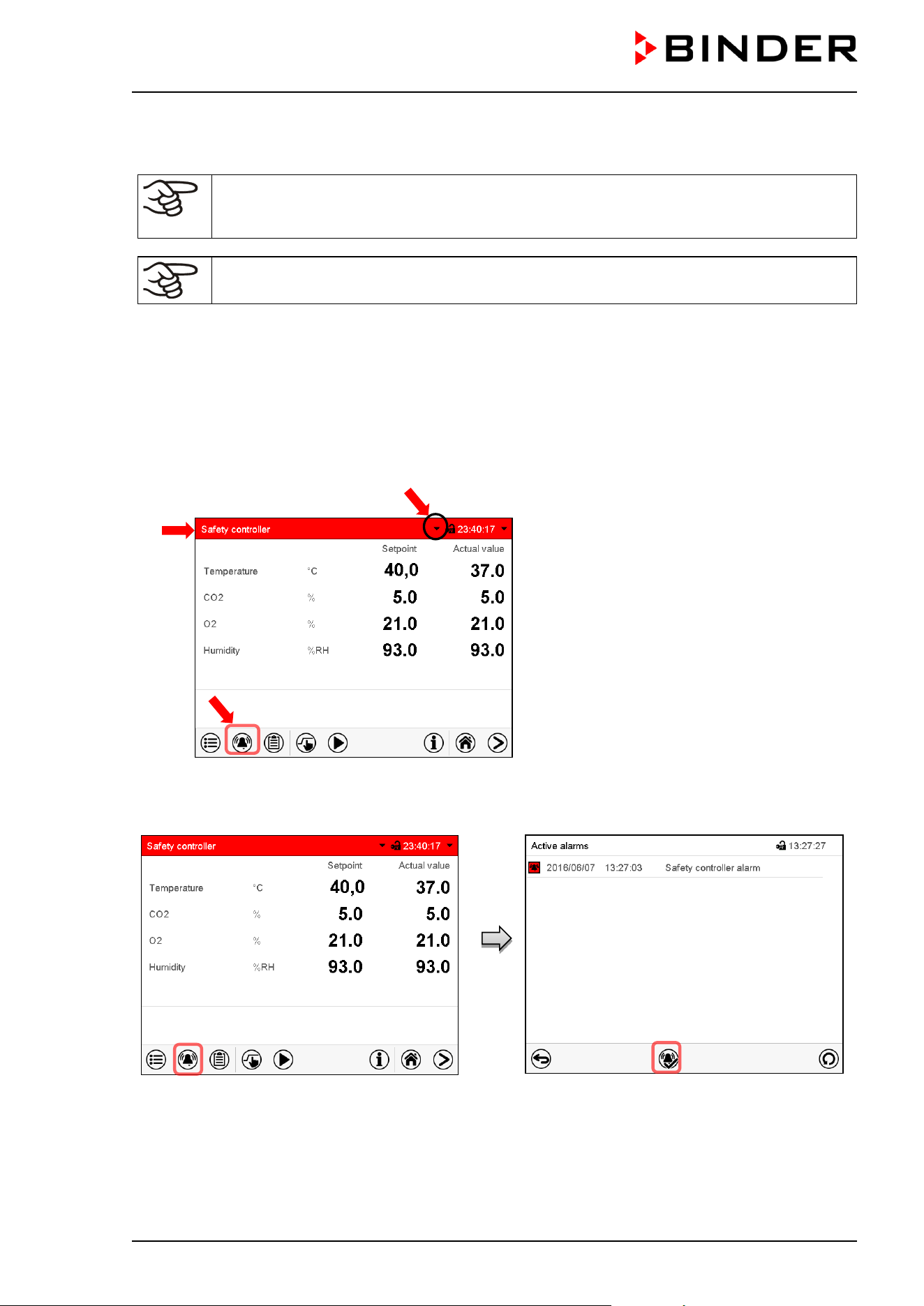
CB / CB-UL, CBF / CBF-UL (E7) 07/2022 Page 104/199
Alarm messages are displayed in the list of active alarms until acknowledging them. They are also shown
in the event list.
When operating the chamber without CO
2
/ O
2
/ N
2
connection, turn off the corresponding
gas control in the “setpoints” menu (chap. 6.7) in order to avoid tolerance range and
pressure alarms.
CBF / CBF-UL: When operating the chamber without water supply, turn off humidity control
in the “setpoints” menu (chap. 6.7) in order to avoid humidity alarms..
11.2 State of alarm
1. Visual indications in Normal display: alarm message, screen header flashing in red color
2. Audible alert, if the buzzer is enabled (chap. 11.4).
3. In some cases: Switching the zero-voltage relay alarm output (chap. 11.6) to transmit the alarm e.g., to
a central monitoring system.
Normal display in state of alarm (example).
(a) Screen header flashing in red
color and
showing the alarm message
(b) Alarm icon on the bottom of the screen:
change to the list of active alarms and
alarm acknowledgement
(c) If applicable, information icon in the screen
header. Indication of a certain condition
11.3 Resetting an alarm, list of active alarms
Normal display in state of alarm (example).
Press the Alarm icon
List of active alarms.
Press the Reset alarm icon.
Pressing the Reset alarm icon mutes the buzzer for all active alarms. The icon then disappears.
• Acknowledging while the alarm condition persists: Only the buzzer turns off. The visual alarm
indication remains on the controller display. The alarm remains in the list of active alarms.
(a)
(c)
(b)
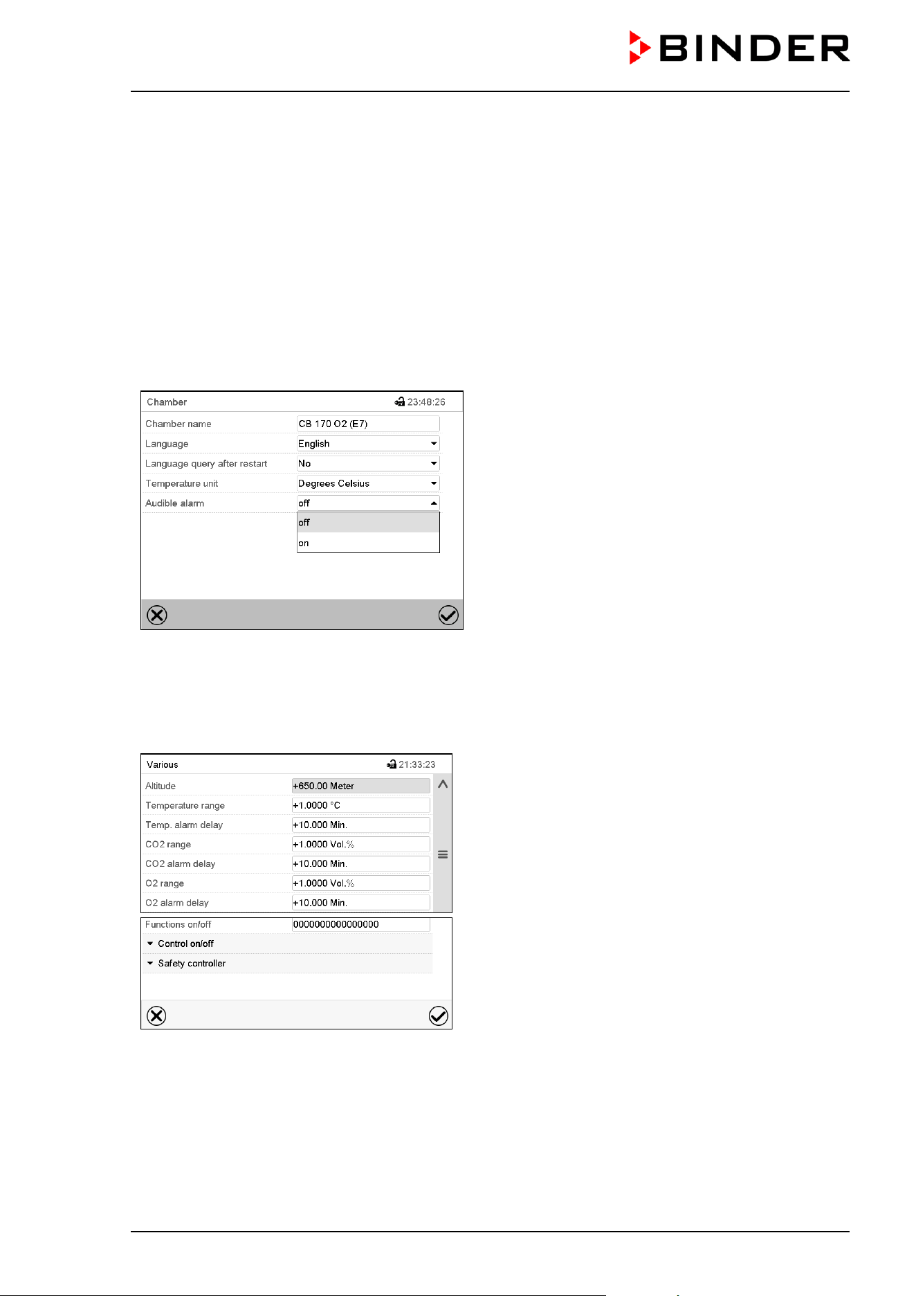
CB / CB-UL, CBF / CBF-UL (E7) 07/2022 Page 105/199
When the alarm condition has ended, the visual alarm indication is automatically cleared. The alarm is
then no longer in the list of active alarms.
• Acknowledging after the alarm condition has ended: The buzzer and the visual alarm indication are reset
together. The alarm is then no longer in the list of active alarms.
• The zero-voltage relay alarm output resets together with the alarm.
For appropriate actions in the event of an alarm, please refer to chap. 22.6 “Troubleshooting”.
11.4 Activating / deactivating the audible alarm (alarm buzzer)
Path: Main menu > Settings > Chamber
“Chamber” submenu (example).
In the field “Audible alarm” select the desired setting
“off“ or “on” and press the Confirm icon.
11.5 Tolerance range settings and alarm delay times
Path: Main menu > Settings > Various
Submenu “Various”.
Select the desired function.
In this menu you can set the deviation between the actual value and setpoint for temperature, CO
2
, O
2
(chamber with O
2
control) and humidity (CBF / CBF-UL) which that shall cause a tolerance range alarm,
and you can define the delay time after which the tolerance alarm will be triggered.
Also you can set the delay time after opening the door will trigger an alarm.
The entered value defines the tolerance range around the setpoint value. Example: Temperature setpoint:
37 °C, tolerance range value: +/- 2 °C, i.e. this defines a tolerance range from 35 °C up to 39 °C.
This function only activates after the set-point has been reached once.
CB / CB-UL, CBF / CBF-UL (E7) 07/2022 Page 106/199
Alarms following deviations from the tolerance range or door opening
If the actual value, after having reached the setpoint, deviates by more than the set tolerance range value
and longer than 10 min. from the setpoint or the temperature doesn’t reach the tolerance range within 3
hours from turning on the chamber or closing the door, after the configured interval (e.g., “Temp range
alarm delay”) an alarm is triggered. It is visually indicated in Normal display. If the alarm buzzer is activated
(chap. 11.4) there is an audible alert. The zero-voltage relay alarm output (chap. 11.6) switches to transmit
the alarm. The alarm is shown in the list of active alarms (chap. 11.3).
Alarm message
Start after condition occurred
“Temperature range” after configurable time
“CO2 range” after configurable time
“O2 range” after configurable time
“Humidity range” after configurable time
“Door open” after configurable time
If the condition (deviation from the tolerance range or door opening) ends within the configured alarm delay
time, no alarm will be triggered after the delay time.
When operating the chamber with deactivated CO
2
, O
2
(chamber with O
2
control) or
humidity (CBF / CBF-UL) control (chap. 6.7), the corresponding tolerance range alarms will
not occur.
Setting:
• Select the field ”Temperature range” and enter the desired value for the temperature range. Setting
range: 1 °C to 10 °C. Confirm entry with Confirm icon.
• Select the field “Temp alarm delay” and enter the time in minutes, after which the range alarm shall be
triggered. Setting range: 1 min to 120 min. Confirm entry with Confirm icon.
• Select the field ”CO2 range” and enter the desired value for the CO
2
range. Setting range: 1 vol.-% to
10 vol.-%. Confirm entry with Confirm icon.
• Select the field “CO2 alarm delay” and enter the time in minutes, after which the range alarm shall be
triggered. Setting range: 1 min to 120 min. Confirm entry with Confirm icon.
• Select the field ”O2 range” and enter the desired value for the O
2
range. Setting range: 1 vol.-% to 10
vol.-%. Confirm entry with Confirm icon.
• Select the field “O2 alarm delay” and enter the time in minutes, after which the range alarm shall be
triggered. Setting range: 1 min to 120 min. Confirm entry with Confirm icon.
• Select the field “Humidity range” and enter the desired value for the humidity range. Setting range: 5%
r.h. to 20% r.h. Confirm entry with Confirm icon.
• Select the field “Humid alarm delay” and enter the time in minutes, after which the range alarm shall be
triggered. Setting range: 1 min to 120 min. Confirm entry with Confirm icon.
• Select the field “Door alarm delay” and enter the time in minutes, after which the range alarm shall be
triggered. Setting range: 1 min to 120 min. Confirm entry with Confirm icon.
After completing the settings, press the Confirm icon to take over the entries and exit the menu, or press
the Close icon to exit the menu without taking over the entries.
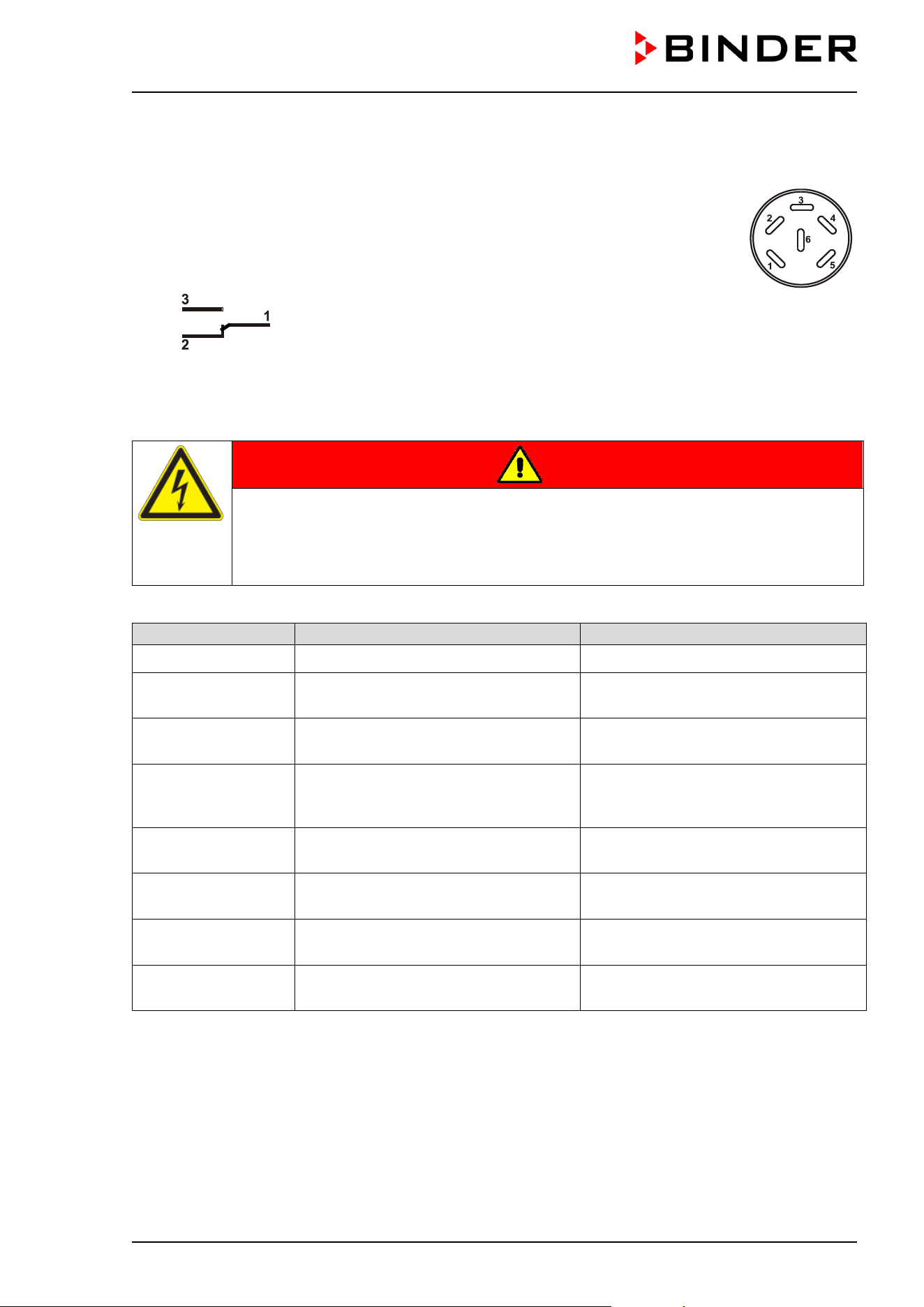
CB / CB-UL, CBF / CBF-UL (E7) 07/2022 Page 107/199
11.6 Zero-voltage relay alarm output
The chamber is equipped with a zero-voltage relay output which permits the transmission
of some alarm messages to a central monitoring system.
The connection is realized as a DIN socket (3) on the chamber rear. A suitable DIN plug
is enclosed.
Figure 40: Pin configuration of the DIN socket (3) on the chamber rear
ALARM
Pin 1: Pole, Pin 2: Break relay, Pin 3: Make contact
In case there is no alarm, contact 1 closes with contact 3.
Closing contact 1 with contact 2 switches the zero-voltage relay alarm output.
Maximum loading capacity of the switching contacts: 24V AC/DC – 2.5A
DANGER
Electrical hazard through overload of switching contacts.
Deadly electric shock. Damage to switching contacts and connection socket.
∅ Do NOT exceed the maximum switching load of 24V AC/DC – 2.5A.
∅ Do NOT connect any devices with a higher loading capacity.
The zero-voltage relay alarm output switches at the following events:
Alarm message
Condition
Switching the alarm contact
---
Power failure immediately
“Temperature range”
Temperature tolerance range alarm
(see chap. 11.1.2)
After configurable delay time (chap.
11.5). Factory setting: 10 minutes
“CO2 range”
CO
2
tolerance range alarm
(see chap. 11.1.2)
After configurable delay time (chap.
11.5). Factory setting: 10 minutes
“O2 range”
O
2
tolerance range alarm
(chamber with O
2
control)
(see chap. 11.1.2)
After configurable delay time (chap.
11.5). Factory setting: 10 minutes
CBF / CBF-UL:
“Humidity range”
Humidity tolerance range alarm
(see chap. 11.1.2)
After configurable delay time (chap.
11.5). Factory setting: 10 minutes
“Door open”
Chamber door open alarm
(see chap. 11.1.2)
After configurable delay time (chap.
11.5). Factory setting: 1 minutes
CBF / CBF-UL:
“Humidity system”
The humidity module is defective
(see chap. 11.1.2)
immediately
CBF / CBF-UL:
“Freshwater supply”
The humidity module cannot fill up
(see chap. 11.1.2)
immediately
In case of a tolerance range alarm or a door open alarm, the alarm message on the controller display
remains on during the alarm transmission via the zero-voltage relay outputs.
As soon as the cause of the alarm is identified and resolved, you can reset the alarm transmission via the
zero-voltage relay outputs together with the alarm message in the “Active alarms” menu by pressing the
Reset alarm icon.
CB / CB-UL, CBF / CBF-UL (E7) 07/2022 Page 108/199
In case of a power failure, transmission of the alarm via zero-voltage relay outputs remains active for the
duration of the power failure. After power returns, contact 1 closes automatically with contact 3.
When using the APT-COM™ 4 Multi Management Software (option, chap. 18.1) for data
acquisition, the alarm messages are only recorded in the protocol.
Set the tolerance limits for limit alarms by APT-COM™ 4 separately in the AlarmCenter.
12. Temperature safety devices
12.1 Over temperature protective device (class 1)
The chamber is equipped with an internal temperature safety device, class 1 acc. to DIN 12880:2007. It
serves to protect the chamber and prevents dangerous conditions caused by major defects.
If the actual temperature exceeds the nominal temperature by approx. 10 °C, the over temperature
protective device permanently turns off the chamber. The user cannot restart the device again. The
protective cut-off device is located internally. Only a service specialist can replace it. Therefore, please
contact an authorized service provider or BINDER Service.
12.2 Overtemperature safety controller class 3.1
The chambers are regularly equipped with an electronic overtemperature safety controller (temperature
safety device class 3.1 according to DIN 12880:2007). The safety controller is functionally and electrically
independent of the temperature control system. If an error occurs, it performs a regulatory function.
Please observe the regulations applicable to your country (for Germany: DGUV guidelines 213-850 on safe
working in laboratories, issued by the employers’ liability insurance association).
The overtemperature safety controller serves to protect the chamber, its environment and the contents from
exceeding the maximum permissible temperature. In the case of an error, it limits the temperature inside
the chamber to the entered safety controller set-point. This condition (state of alarm) is indicated visually
and additionally with an audible alert if the buzzer is enabled (chap. 11.4). The alarm persists until the
chamber cools down below the configured safety controller setpoint.
Check the setting regularly and adjust it following changes of the set-point or charge.
During a running sterilization (chap. 21.3) the safety controller is non-functional
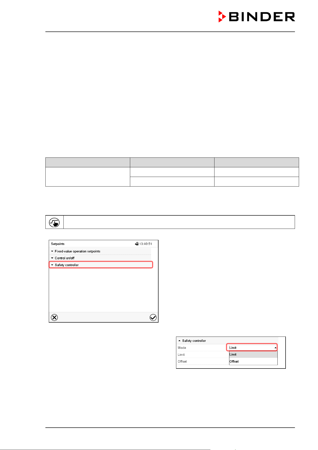
CB / CB-UL, CBF / CBF-UL (E7) 07/2022 Page 109/199
12.2.1 Safety controller modes
You can select between “Limit (absolute)” and “Offset (relative)” safety controller mode
• Limit: Absolute maximum permitted temperature value
This setting offers high safety as a defined temperature limit will not be exceeded. It is important to adapt
the safety controller set-point after each modification of the temperature set-point. Otherwise, the limit
could be too high to ensure efficient protection, or, in the opposite case, it could prevent the controller
from reaching an entered set-point outside the limit range.
• Offset: Maximum overtemperature above any active temperature set point. The maximum temperature
changes internally and automatically with every set-point change.
This setting is recommended for program operation. It is important to check the safety controller set-
point and safety controller mode occasionally, as it does not offer a fix, independent limit temperature
value, which would never be exceeded.
Example: Desired temperature value: 37 °C, desired safety controller value: 39 °C.
Possible settings for this example:
Temperature set point Safety controller mode Safety controller set-point
37 °C
Limit (absolute) 39 °C
Offset (relative) 2 °C
12.2.2 Setting the safety controller
Press the Setpoint setting icon to access the “Setpoint” setting menu from Normal display.
“Setpoints” menu.
Select the field “Safety controller” to access the
settings.
•
In the field “Mode” select the desired setting
“Limit” or “Offset”.
• Select the corresponding field “Limit” or “Offset” according to the selected mode and enter the desired
safety controller setpoint. Confirm entry with Confirm icon.
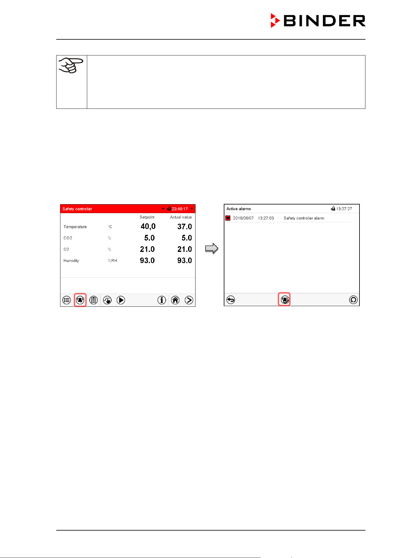
CB / CB-UL, CBF / CBF-UL (E7) 07/2022 Page 110/199
Regularly check the safety controller setting for set-point type “Limit” or “Offset”
• in Fixed value operating mode according to the entered set-point temperature value
•
in program mode according to the highest temperature value of the selected temperature
program
Set the safety controller set-point by approx. 2 °C above the desired temperature set-point.
After completing the settings, press the Confirm icon to take over the entries and exit the menu, or press
the Close icon to exit the menu without taking over the entries.
12.2.3 Message and measures in the state of alarm
The state of alarm is indicated visually in Normal display by the alarm message “Safety controller alarm”
and the screen header flashing in red color. If the buzzer is enabled (chap. 11.4) there is an additional
audible alert (chap. 11.2). The alarm remains active until it is acknowledged on the controller and the inner
temperature falls below the set safety controller setpoint. Then the heating is released again.
Normal display with safety controller alarm.
Press the Alarm icon
List of active alarms.
Press the Reset alarm icon.
12.2.4 Function check
Check the safety controller at appropriate intervals for its functionality. It is recommended that the
authorized operating personnel should perform such a check, e.g., before starting a longer work procedure.

CB / CB-UL, CBF / CBF-UL (E7) 07/2022 Page 111/199
13. User management
13.1 Authorization levels and password protection
The available functions depend on the current authorization level “Master”, “Service”, “Admin” or “User”.
The authorization levels are hierarchical: Every authorization includes all functions of the next lower level.
“Master” authorization level
• Highest authorization level, only for developers
• Extensive authorization for controller operation and configuration, outputs/inputs, alarm settings,
parameter sets and operating ring display
• All passwords can be changed in the “log out” submenu (chap. 13.3).
“Service” authorization level
• Authorization level only for BINDER service
• Extensive authorization for controller operation and configuration, access to service data
• The passwords for “Service”, “Admin” and “User” authorization levels can be changed in the “log out”
submenu (chap. 13.3).
“Admin” authorization level
• Expert authorization level, for the administrator
• Authorization for controller configuration and network settings and for operating those controller
functions required for operating the chamber. Restricted access to service data.
• Password (factory setting): “2”.
• The passwords for “Admin” and “User” authorization levels can be changed in the “log out” submenu
(chap. 13.3).
“User” authorization level
• Standard authorization level for the chamber operator
• Authorization for operating the controller functions required for operating the chamber.
• No authorization for controller configuration and network settings. The “Settings” and “Service”
submenus of the main menu are not available.
• Password (factory setting): “1”
• The password for the “User” authorization level can be changed in the “log out” submenu (chap. 13.3).
As soon as a password has been assigned for an authorization level, the access to this level and the related
controller functions are only available after log-in with the appropriate password.
If for an authorization level no password is assigned, the related controller functions of this level are
available for every user without login.
If passwords have been assigned for all authorization levels, access to the controller functions is locked
without login.
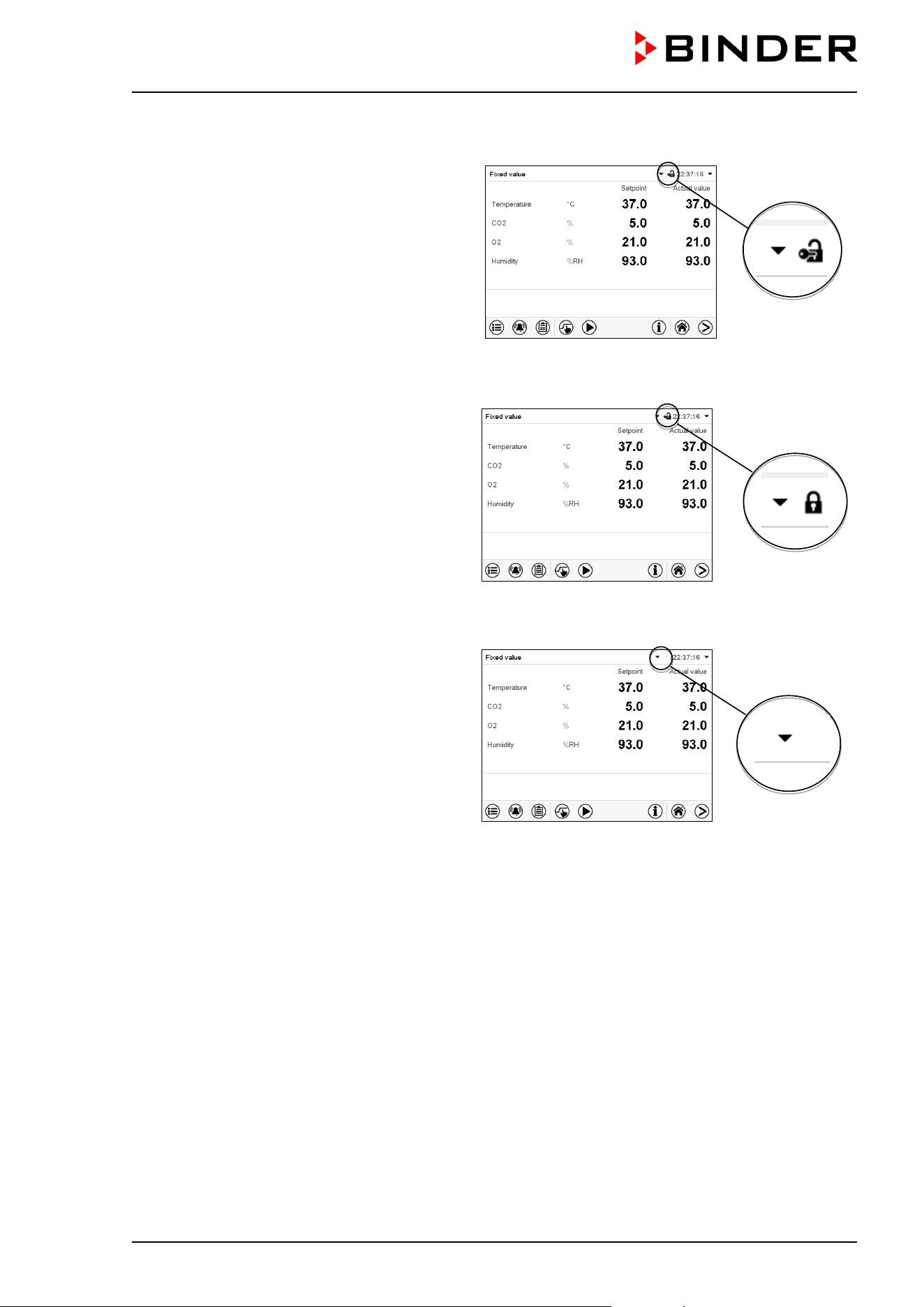
CB / CB-UL, CBF / CBF-UL (E7) 07/2022 Page 112/199
Operation after user login
At user login, the authorization level is selected
and confirmed by entering the respective
password.
Following user login, controller operation is
available, recognizable by the open-lock icon in
the header. The available controller functions
correspond to the user’s authorization level.
Password protection activated for all levels: operation without user login is locked
If passwords have been assigned for all
authorization levels, the controller is locked
without registration of a user.
As long as no user is registered, controller
operation is locked, recognizable at the closed-
lock icon in the header. This requires that the
user management has been activated by the
assignment of passwords for the individual
authorization levels.
Password protection for at least one level deactivated: operation without user login is possible
If passwords have not been assigned for all
authorization levels, after turning on the
chamber there are those controller functions
available, which correspond to the highest
authorization level without password
protection.
No lock icon is shown in the display header.
User login is neither required nor possible.
To activate the password protection and user
login, perform new password assignment
(chap. 13.5.3).
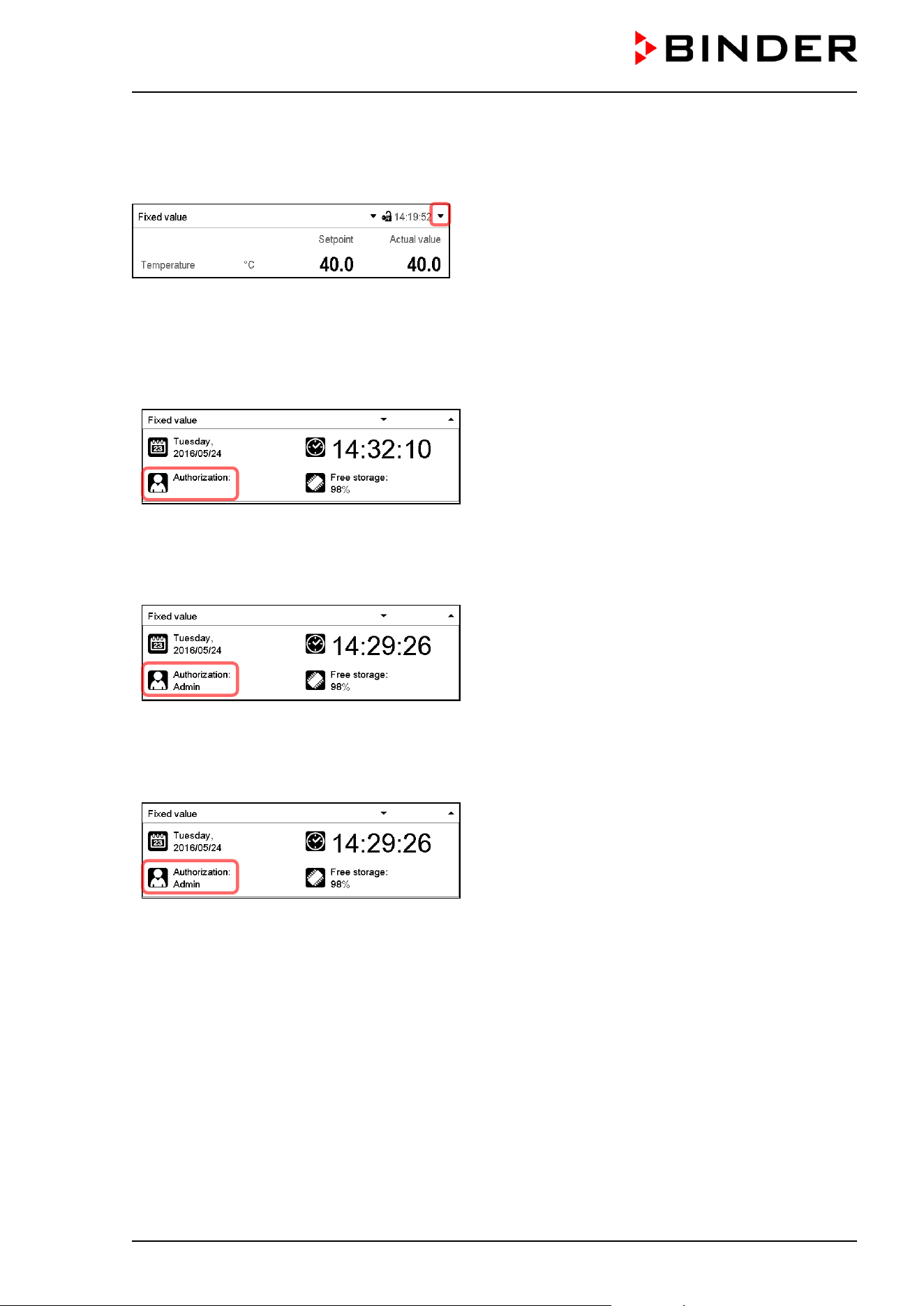
CB / CB-UL, CBF / CBF-UL (E7) 07/2022 Page 113/199
Information window
To check the authorization level of the user currently logged-in, select in Normal display the arrow far right
in the display header.
The information window shows date and time, the controller’s free memory space and under “Authorization”
the authorization level of the current user.
If passwords have been assigned for all authorization levels, a user without login (password entry) has no
authorization. There are only viewing functions available.
Display when all authorization levels are password
protected and no user has logged in:
No authorization level is displayed.
If passwords have been assigned only for some of the authorization levels, a user without login (password
entry) has access to the functions of the highest authorization level without password protection.
Display when only some of the authorization levels
are password protected (example: no protection for
the “User” and “Admin” levels) and no user has
logged in:
The user’s effective authorization (due to lack of
password protection) is shown.
Example: user with “Admin” authorization.
If passwords have been assigned for some or all of the authorization levels, user login (password entry)
provides the authorization for the corresponding password-protected level.
Display when at least some of the authorization levels
are password protected and a user has logged in.
The user’s authorization (by password entry) is
shown.
Example: user with “Admin” authorization.
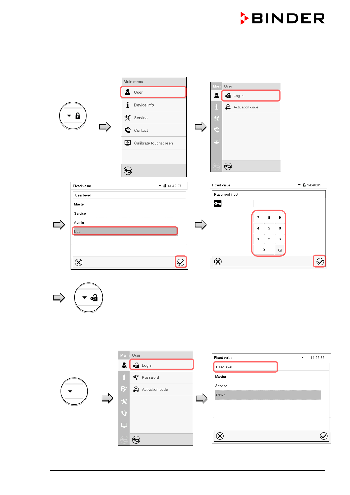
CB / CB-UL, CBF / CBF-UL (E7) 07/2022 Page 114/199
13.2 Log in
Path: Main menu > User > Log in
Controller
without a user
logged-in
Selection of user type (example) All selection possibilities are password protected
Controller with logged-in user
After completing the settings, press the Confirm icon to take over the entries and exit the menu, or press
the Close icon to exit the menu without taking over the entries.
Controller with
deactivated
password
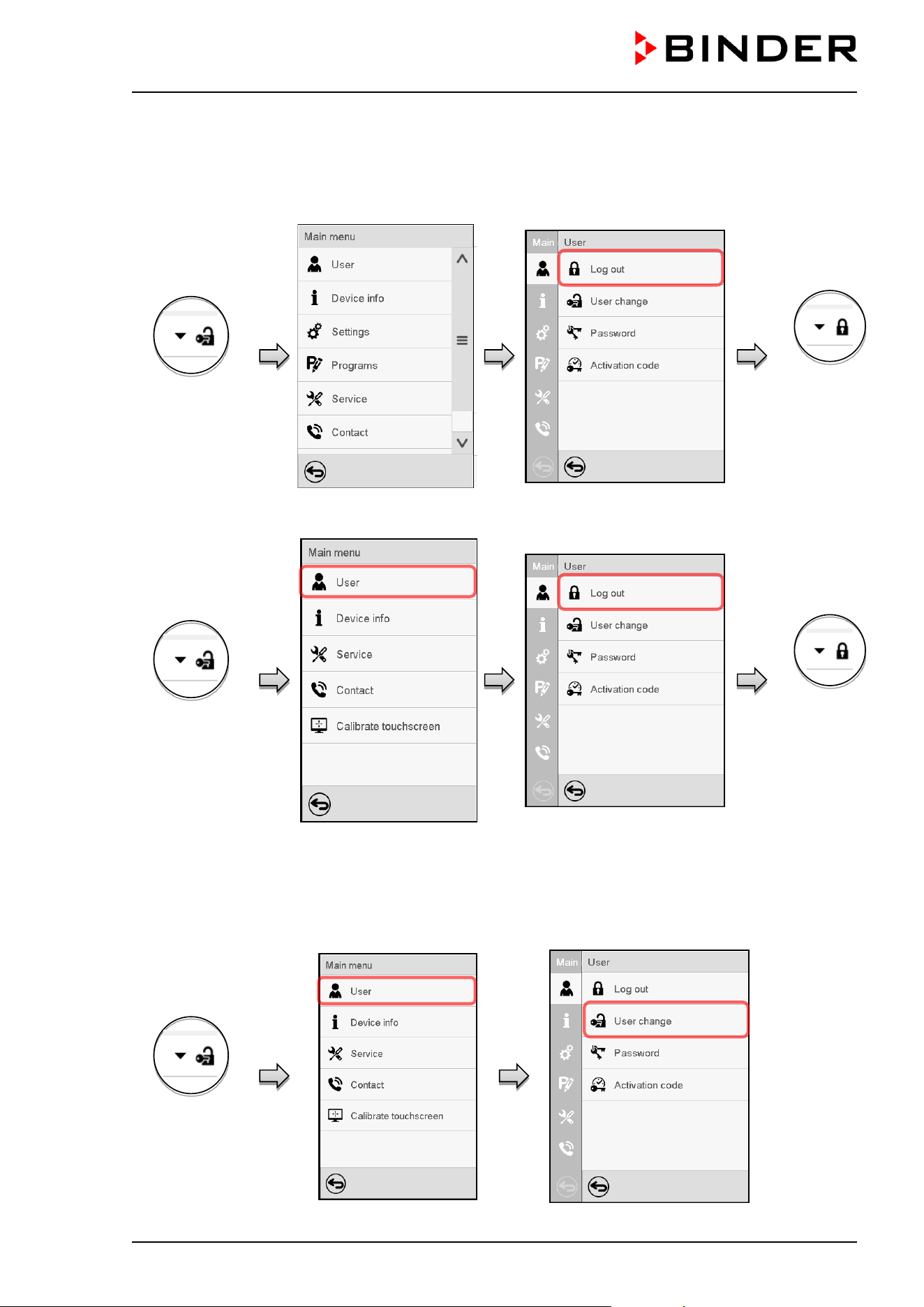
CB / CB-UL, CBF / CBF-UL (E7) 07/2022 Page 115/199
13.3 Log out
Path: Main menu > User > Log out
User logoff with “Admin” authorization
Controller with
logged-in user
Controller
without a user
logged-in
User logoff with “Admin” authorization
Controller with
logged-in user
Controller
without a user
logged-in
13.4 User change
If the password function has been deactivated (chap.13.5.2) this function is not available.
Path: Main menu > User > User change
Controller with
logged-in user
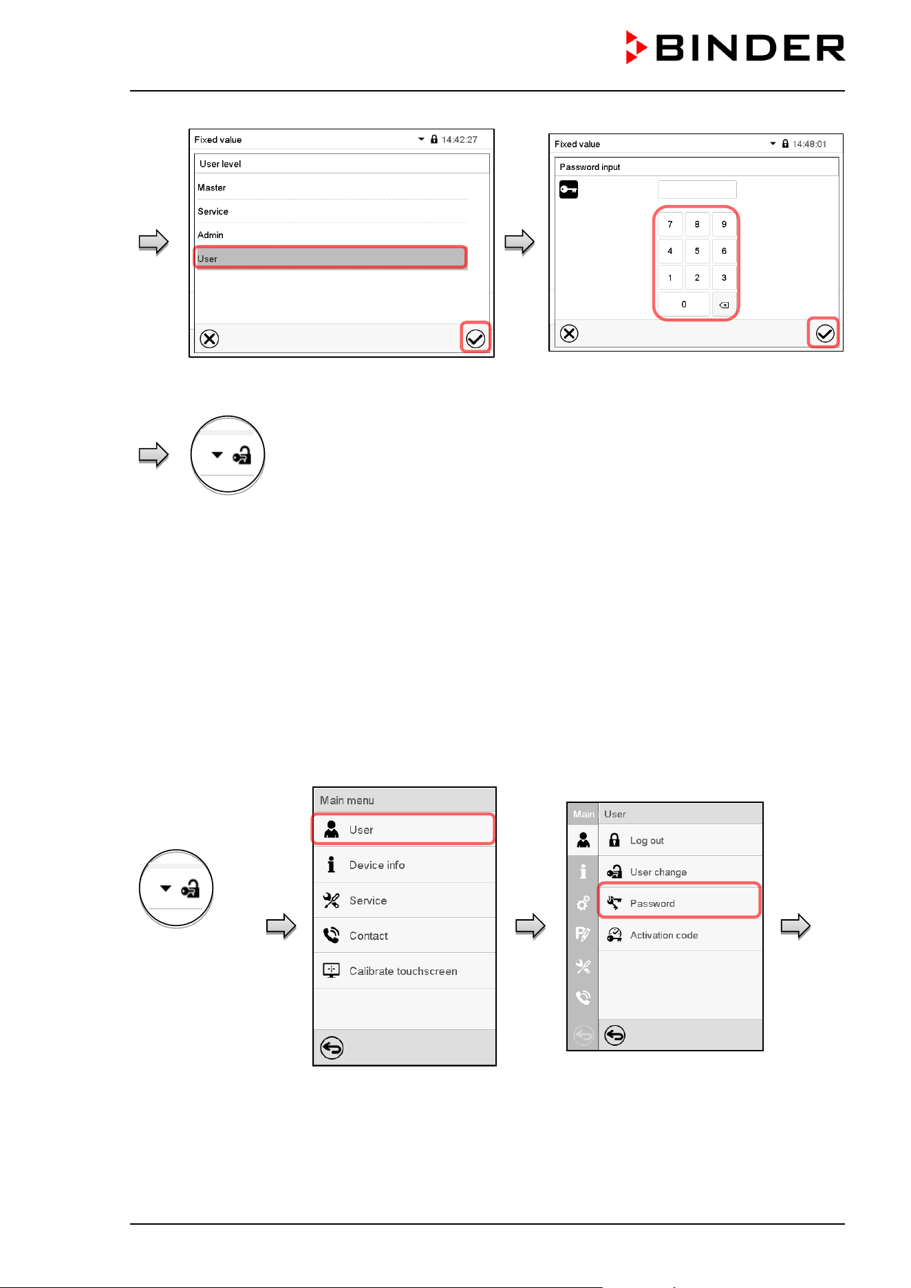
CB / CB-UL, CBF / CBF-UL (E7) 07/2022 Page 116/199
User selection (example) All selection possibilities are password protected
Controller with logged-in
user
13.5 Password assignment and password change
This function is not available for a user logged-in with “User” authorization.
13.5.1 Password change
A logged-in user can change the passwords of his current level and of the next lower level(s).
Example: A user with “Admin” authorization can change the passwords for the “Admin” and “User”
authorization levels.
Path: Main menu > User > Password
User logged-in
with “Service” or
“Admin”
authorization
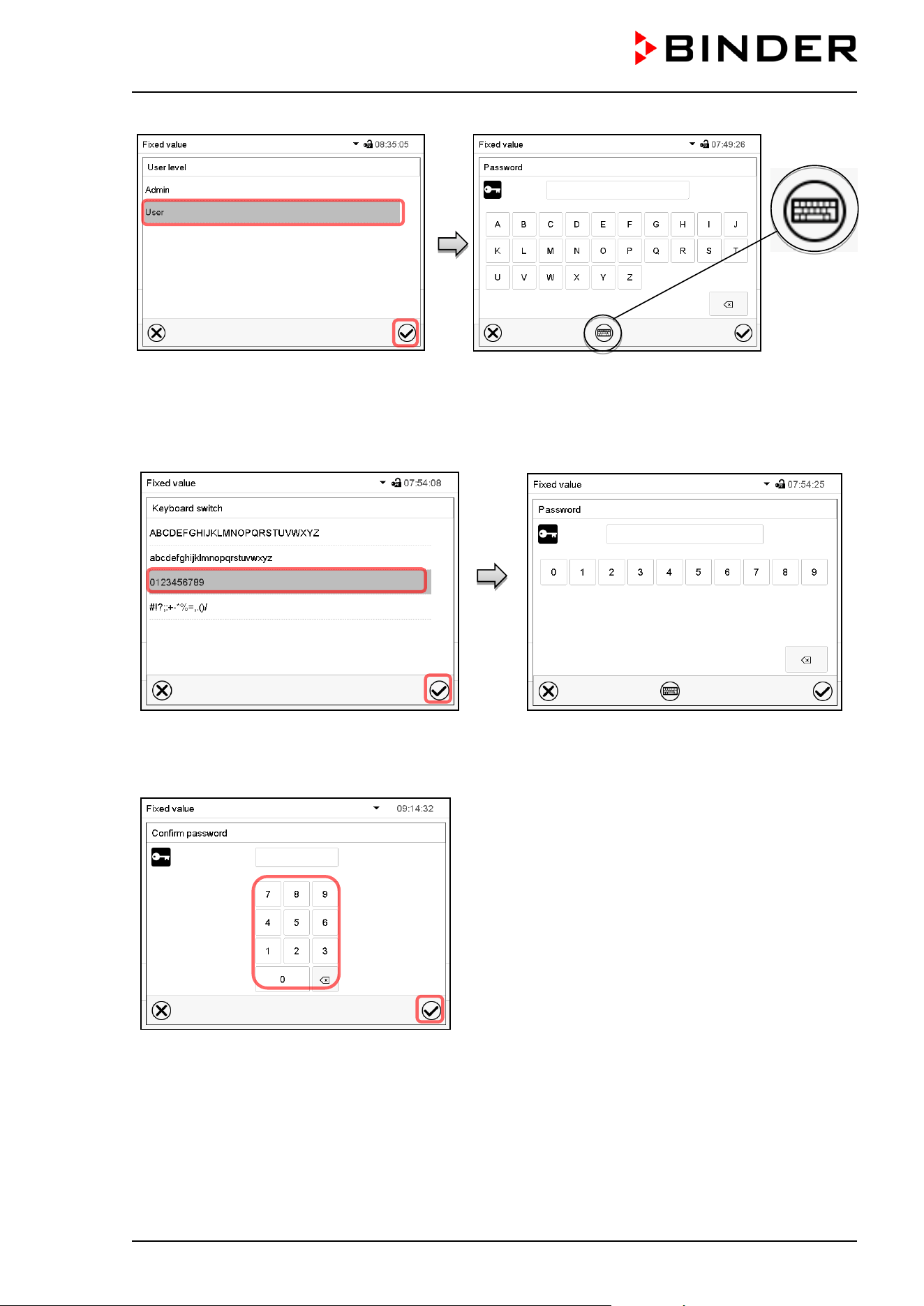
CB / CB-UL, CBF / CBF-UL (E7) 07/2022 Page 117/199
Selection of the authorization level
(example: view with “Admin” authorization)
Enter desired password. If desired, press the Change
keyboard icon to access other entry windows.
In the “Keyboard switch” window you can select different keyboards to enter uppercase and lowercase
letters, digits, and special characters. All types of characters can be combined within one single password.
Example: access the digit entry window
Entry of digits
To confirm the entry, press the Confirm icon.
Repeat the password entry for confirmation (sample
picture). For each character of the password, the
required keyboard appears automatically.
Then press the Confirm icon.
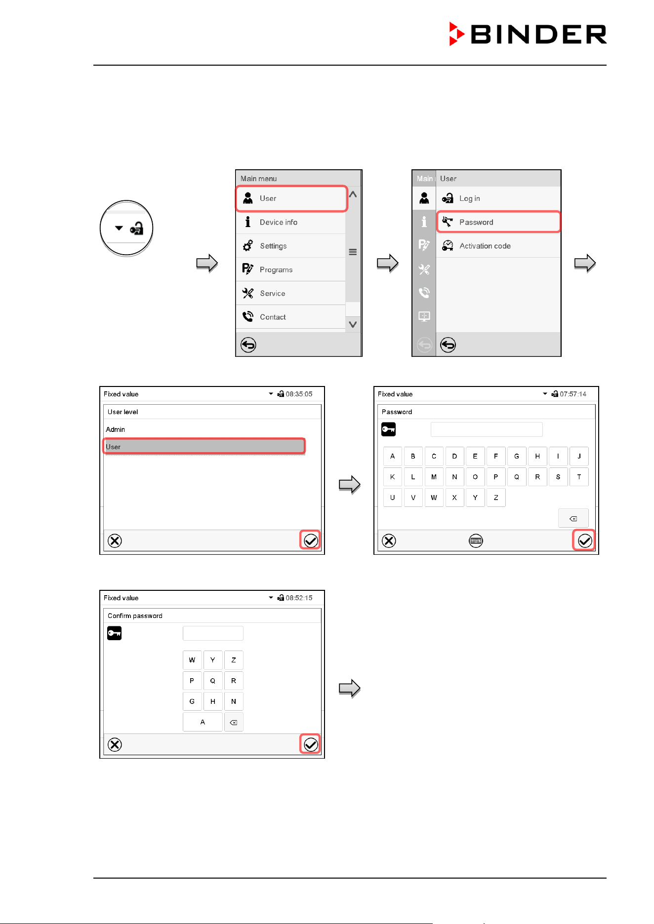
CB / CB-UL, CBF / CBF-UL (E7) 07/2022 Page 118/199
13.5.2 Deleting the password for an individual authorization level
A user logged-in with “Service” or “Admin” authorization can delete the passwords of his current level and
of the next lower level(s). To do this no password is entered during a password change.
Path: Main menu > User > Password
Controller with
logged-in user
(e.g. with
“Admin”
authorization)
Select the authorization level for which the
password shall be deleted.
Do NOT enter anything in the “Password”
screen. Press the Confirm icon.
Do NOT enter anything in the “Confirm
password” screen. Press the Confirm icon.
The password is deleted.
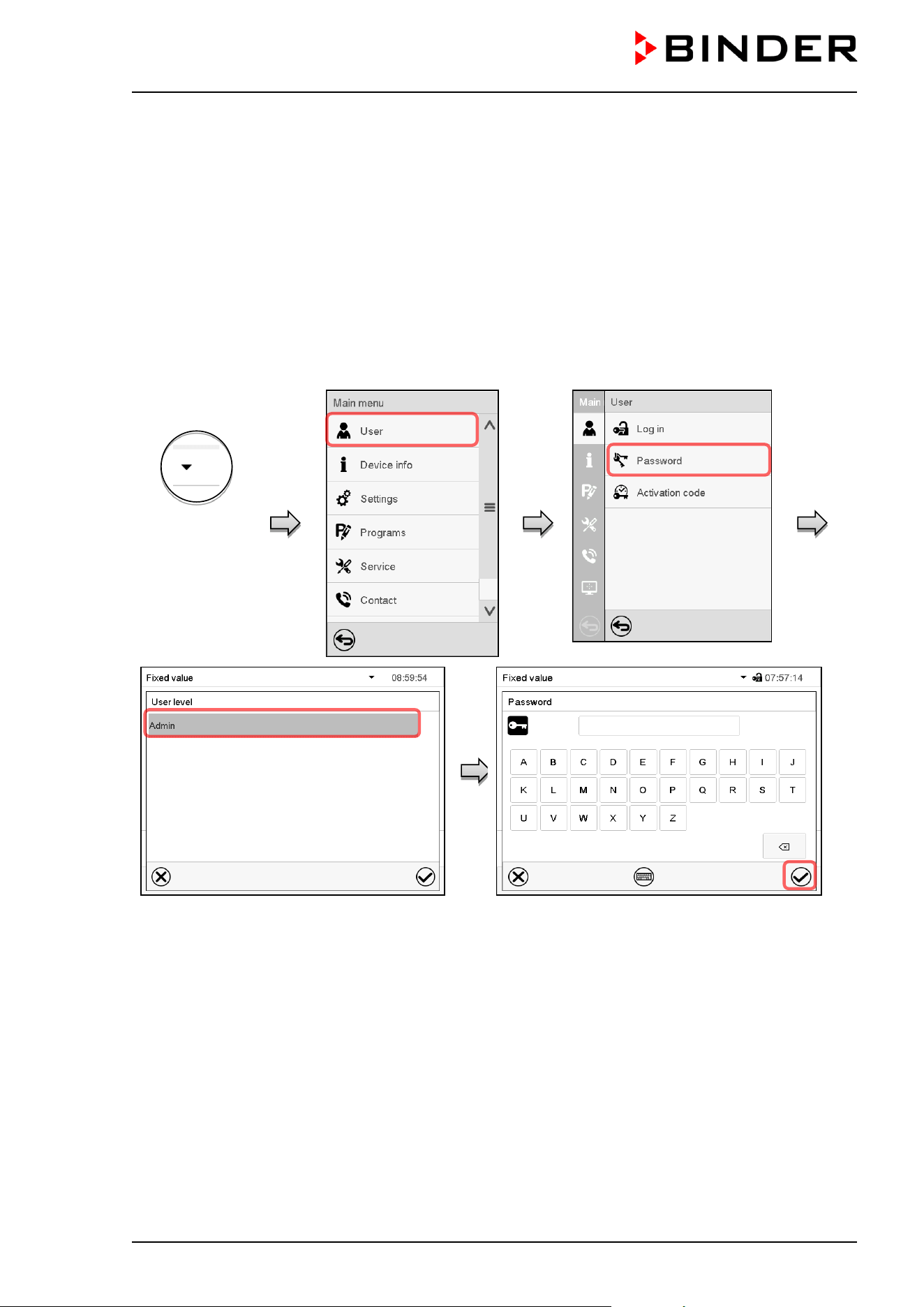
CB / CB-UL, CBF / CBF-UL (E7) 07/2022 Page 119/199
13.5.3 New password assignment for “service” or “admin” authorization level when the
password function was deactivated
If the password protection for an authorization level has been deactivated, i.e., no password is assigned,
no login for this level is possible. Therefore access to this authorization level is available without login.
If the password for the “Service” or “Admin” authorization has been deleted (chap. 13.5.2), a new password
can be assigned for the current level and the next lower level(s) without user login.
Example: The password for the “Admin” authorization level was deleted, therefore every user without login
has full access to the functions of the “Admin” authorization level. If access to this level shall become
password protected again, the user can assign a new password for the “Admin” authorization level with the
“Password” function.
Path: Main menu > User > Password
Controller with
deactivated
password for
“Service” or
“Admin”
authorization
Select the authorization level, for which you
want to assign a password.
(Example: “Admin” authorization)
Enter the desired password. If desired, press the
Change keyboard icon to access other entry
windows.
To confirm the entry, press the Confirm icon.
Repeat the password entry for confirmation. For each character of the password, the required keyboard
appears automatically. Then press the Confirm icon.
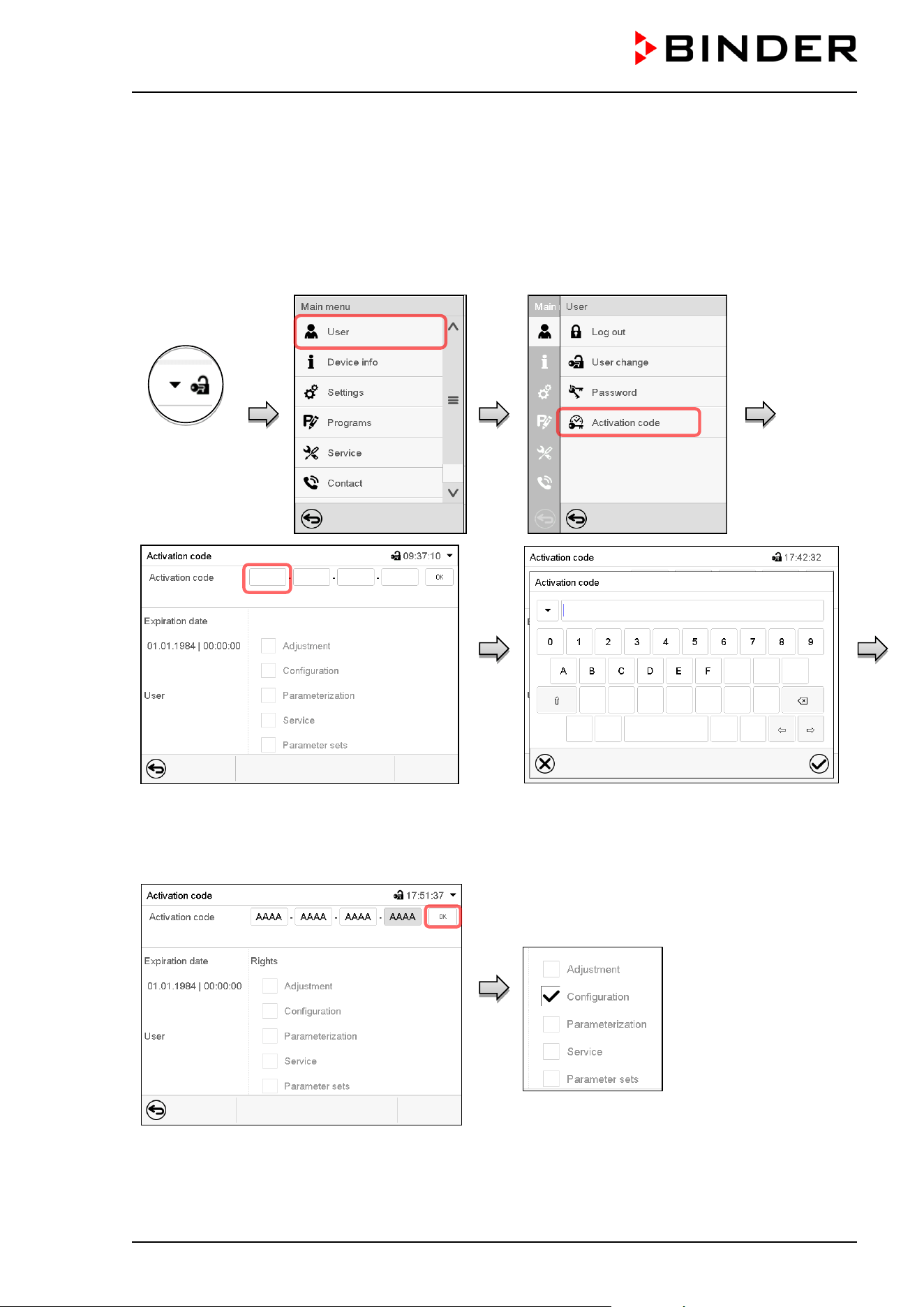
CB / CB-UL, CBF / CBF-UL (E7) 07/2022 Page 120/199
13.6 Activation code
Certain functions of the controller can be unlocked with a previously generated activation code.
The activation code enables access to functions available only in the “Service” authorization level by users
without a “Service” authorization. Such functions include e.g., adjustment or extended configurations.
The activation code is available in authorization levels.
Path: Main menu > User> Activation code
Controller
with logged-
in user
Activation code menu.
Select the first of the four entry fields.
Activation code entry window.
Enter the first four characters of the activation
code and press the Confirm icon.
Select the next of the four entry fields and proceed accordingly until the entire code has been entered.
“Activation code” menu with entered code
(sample view).
Press OK to take over the entry.
The available functions are indicated by marked
checkboxes.
Example: Extended configurations available.
Under “Expiration date” the date of expiry of the
code is displayed.
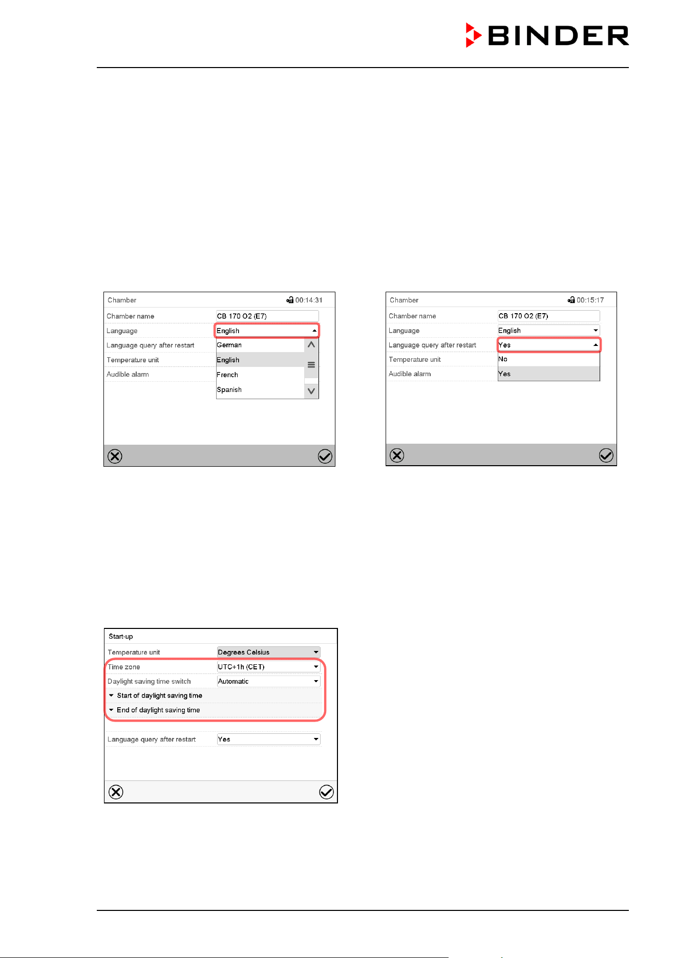
CB / CB-UL, CBF / CBF-UL (E7) 07/2022 Page 121/199
14. General controller settings
Most of the general settings can be accessed in the “Settings” submenu, which is available for users with
“Service” or “Admin” authorization level. It serves to enter date and time, select the language for the
controller menus and the desired temperature unit and to configure the controller’s communication
functions.
14.1 Selecting the controller’s menu language
The MB2 program controller communicates by a menu guide using real words in German, English, French,
Spanish, and Italian.
Path: Main menu > Settings > Chamber
“Chamber” submenu.
Select the desired language.
“Chamber” submenu.
Select if there shall be a language query after
restarting the chamber and press the Confirm
icon.
Return to Normal display with the Back icon to take over the entries.
14.2 Setting date and time
Following start-up of the chamber after language selection:
Select the time zone and configure the daylight
saving time switch.
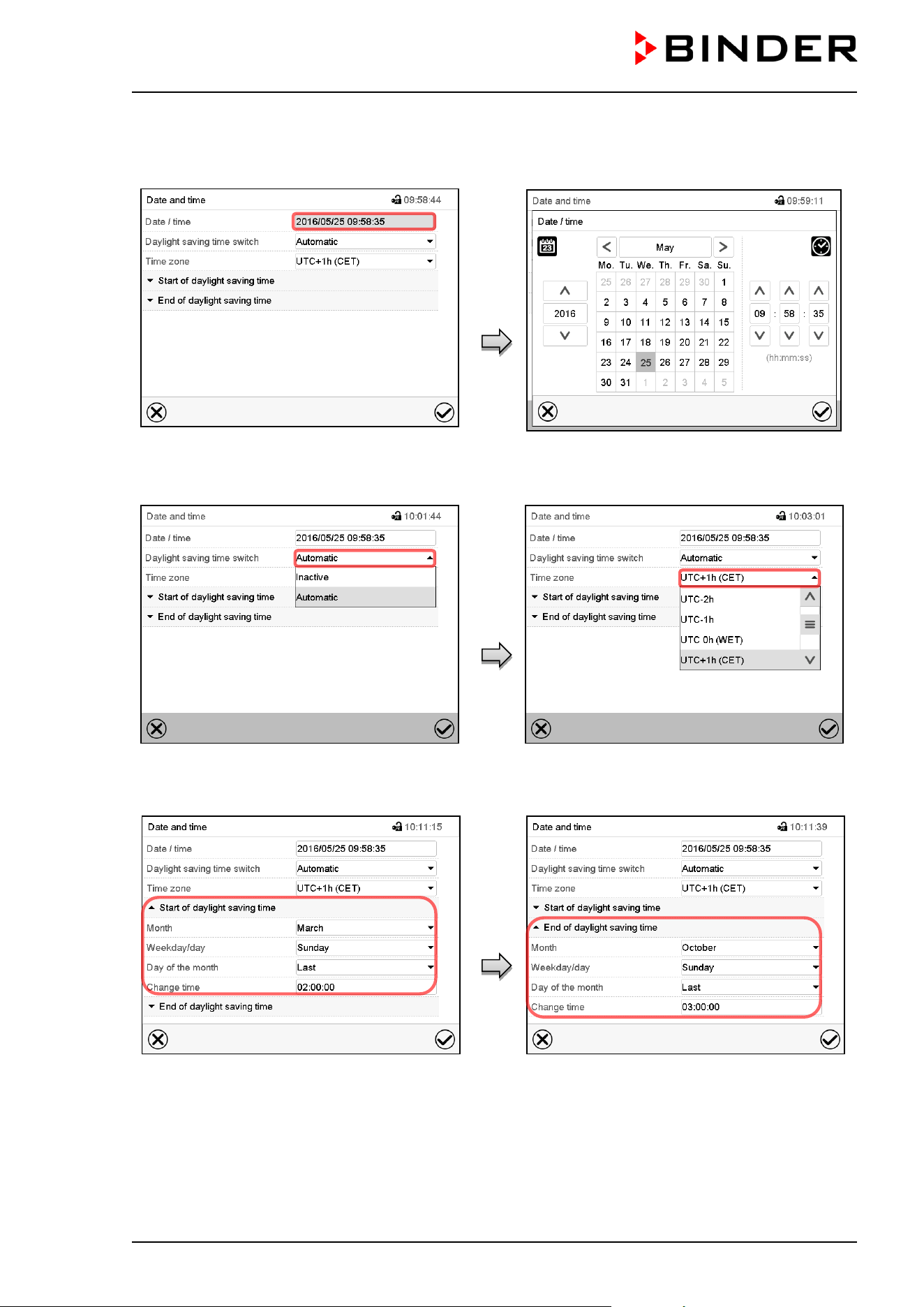
CB / CB-UL, CBF / CBF-UL (E7) 07/2022 Page 122/199
Or later:
Path: Main menu > Settings > Date and time
“Date and time” submenu.
Select the field “Date / time”.
“Date / time” entry menu.
Enter date and time and press the Confirm
icon.
“Date and time” submenu.
In the field “Daylight saving time switch” select
the desired setting “Automatic” or “Inactive”.
“Date and time” submenu.
Select the desired time zone and press the
Confirm icon.
“Date and time” submenu.
Select the desired start of the daylight saving
time.
“Date and time” submenu.
Select the desired end of the daylight saving
time and press the Confirm icon.
After completing the settings, press the Confirm icon to take over the entries and exit the menu, or press
the Close icon to exit the menu without taking over the entries.
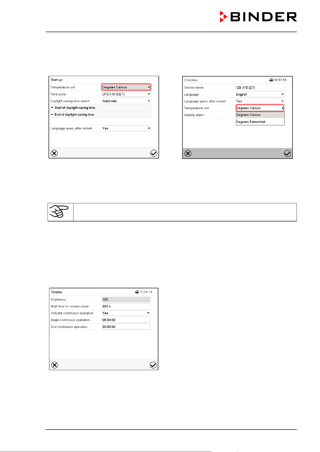
CB / CB-UL, CBF / CBF-UL (E7) 07/2022 Page 123/199
14.3 Selecting the temperature unit
Following start-up of the chamber:
Or later:
Path: Main menu > Settings > Chamber
Select the desired temperature unit and press
the Confirm icon.
Change of the temperature unit between °C and °F.
If the unit is changed, all values are converted accordingly
C = degree Celsius
F= degree Fahrenheit
0 °C = 31°F
100 °C = 212°F
Conversion:
[value in °F] = [value in °C] ∗ 1,8 + 32
14.4 Display configuration
14.4.1 Adapting the display parameters
This function serves to configure parameters like display brightness and operating times.
Path: Main menu > Settings > Display > Display
“Display” submenu.
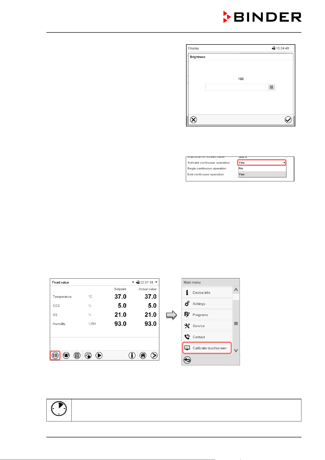
CB / CB-UL, CBF / CBF-UL (E7) 07/2022 Page 124/199
• Select the field “Brightness”.
Move the grey slide to the left or right to define the
brightness of the display
• left = darker (minimum value: 0)
• right = brighter (maximum value: 100)
Press the Confirm icon.
• Select the field “Wait time for screen saver” and enter the desired waiting time for the screen saver in
seconds. Setting range: 10 sec up to 32767 sec. During the waiting time the display is off. Confirm entry
with Confirm icon.
• In the field “Activate continuous operation” select
the desired setting “Yes” or “No”.
• Select the field “Begin continuous operation” (possible only if continuous operation is activated) and
enter the time with the arrow keys. Confirm entry with Confirm icon.
• Select the field “End continuous operation. (only possible if continuous operation is activated) and enter
the time with the arrow keys. Confirm entry with Confirm icon.
After completing the settings, press the Confirm icon to take over the entries and exit the menu, or press
the Close icon to exit the menu without taking over the entries.
14.4.2 Touchscreen calibration
This function serves to optimize the display for the user’s individual angular perspective.
Path: Main menu > Calibrate touchscreen
Normal display.
Select “Calibrate touchscreen” and follow the instructions on the display.
You need to touch all four corners of the touchscreen to calibrate it. Appropriate boxes appear successively
in each corner.
The waiting icon shows how much time there is left to touch the currently activated box. If
the box is not touched withing this period, calibration is aborted and the display changes to
Normal display.
After completing the calibration, i.e., touching all four boxes, the display changes to Normal display.
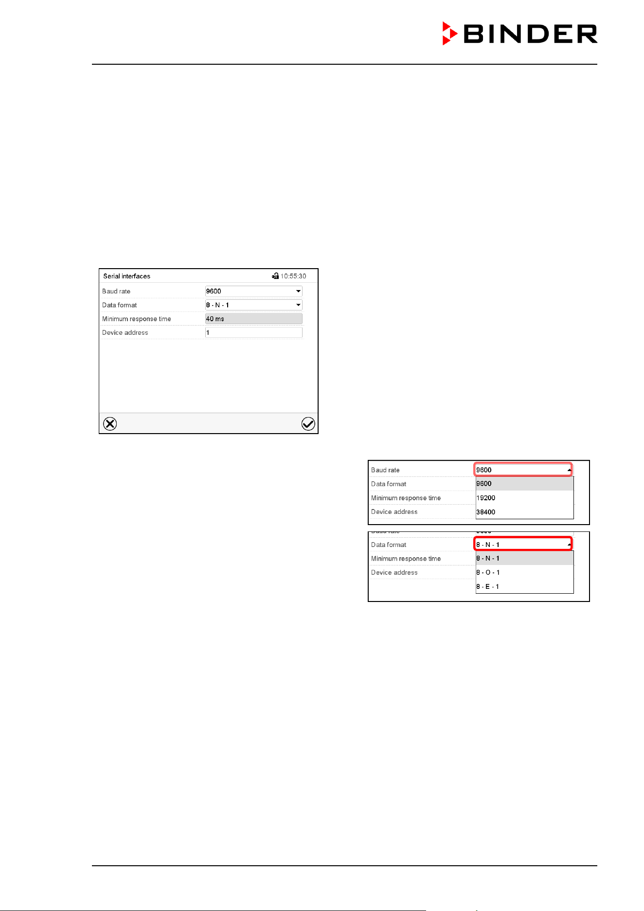
CB / CB-UL, CBF / CBF-UL (E7) 07/2022 Page 125/199
14.5 Network and communication
For these settings at least the “Admin” authorization level is required.
14.5.1 Serial RS485 interface (available via BINDER INDIVIDUAL Customized Solutions)
This menu allows to configure the communication parameters of the RS485 interface.
The device address is required to recognize chambers with this interface type in a network, e.g. when
connecting it to the optional BINDER APT-COM™ 4 Multi Management Software (chap. 18.1). In this case
do not change the other parameters.
Path: Main menu > Settings > Serial interfaces
“Serial interfaces” submenu.
• Select the desired setting in the field “Baud rate”.
• Select the desired setting in the field “Data format”.
• Select the field “Minimum response time” and enter the desired minimum response time. Confirm entry
with Confirm icon.
• Select the field “Device address” and enter the device adress. Factory setting is “1”. Confirm entry with
Confirm icon.
After completing the settings, press the Confirm icon to take over the entries and exit the menu, or press
the Close icon to exit the menu without taking over the entries.
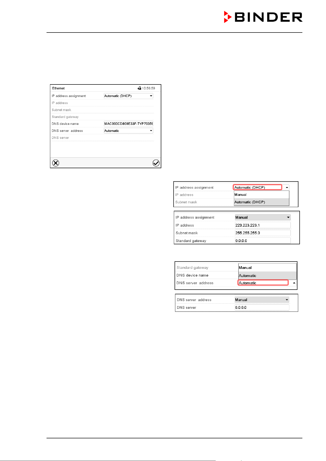
CB / CB-UL, CBF / CBF-UL (E7) 07/2022 Page 126/199
14.5.2 Ethernet
14.5.2.1 Configuration
Path: Main menu > Settings > Ethernet
“Ethernet” submenu.
• In the field “IP address assignment” select the
desired setting “Automatic (DHCP)“ or
“Manual“.
With selection “Manual” you can enter the IP-
address, the subnet mask and the standard
gateway manually.
• Select “DNS device name” and enter the DNS device name. Confirm entry with Confirm icon.
• In the field “DNS server address” select the
desired setting “Automatic” or “Manual”.
With selection „Manual“ you can enter the DNS
server address manually.
After completing the settings, press the Confirm icon to take over the entries and exit the menu, or press
the Close icon to exit the menu without taking over the entries.
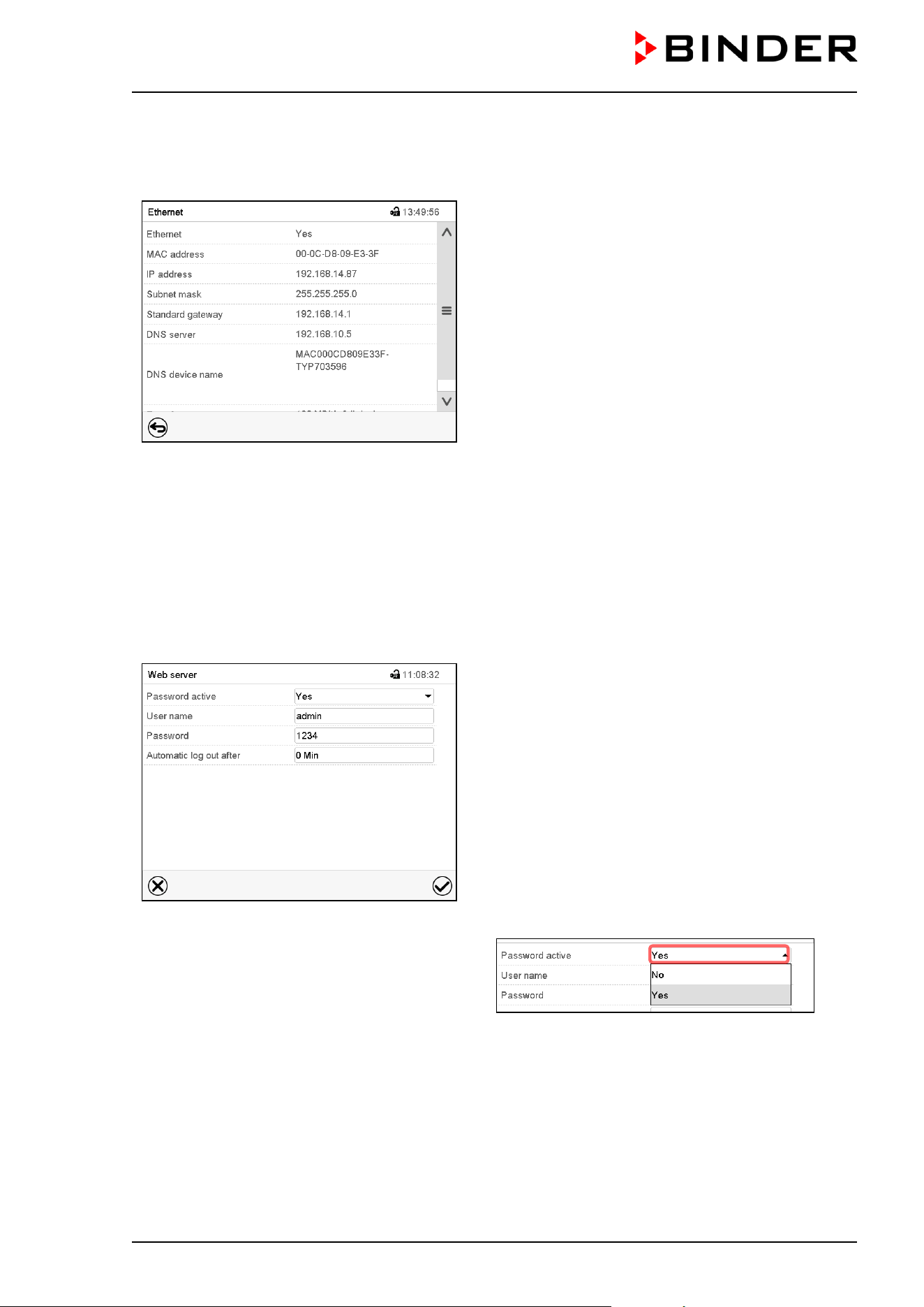
CB / CB-UL, CBF / CBF-UL (E7) 07/2022 Page 127/199
14.5.2.2 Display of MAC address
Path: Main menu > Device info > Ethernet
“Ethernet” submenu (example).
14.5.3 Web server
This controller menu serves to configure the web server. Then you can enter the chamber’s IP-address in
the Internet. The IP address is available via Chamber information > Ethernet. The BINDER web server
opens. Enter the user name and password which have been assigned for the web server in the controller
menu. This enables online access to the controller display, to see e.g., the event list or error messages. In
this view no settings can be changed.
Path: Main menu > Settings > Web server
“Webserver” submenu.
• In the field “Password active” select the desired
setting “Yes” or “No”.
• Select the field “User name” and enter the desired user name. Confirm entry with Confirm icon.
• Select the field “Password” and enter the desired password. Confirm entry with the Confirm icon.
• Select the field “Automatic log out after” and enter the time in minutes after which the webserver shall
log out automatically. Setting range: 0 min to 65535 min. Confirm entry with Confirm icon.
After completing the settings, press the Confirm icon to take over the entries and exit the menu, or press
the Close icon to exit the menu without taking over the entries.
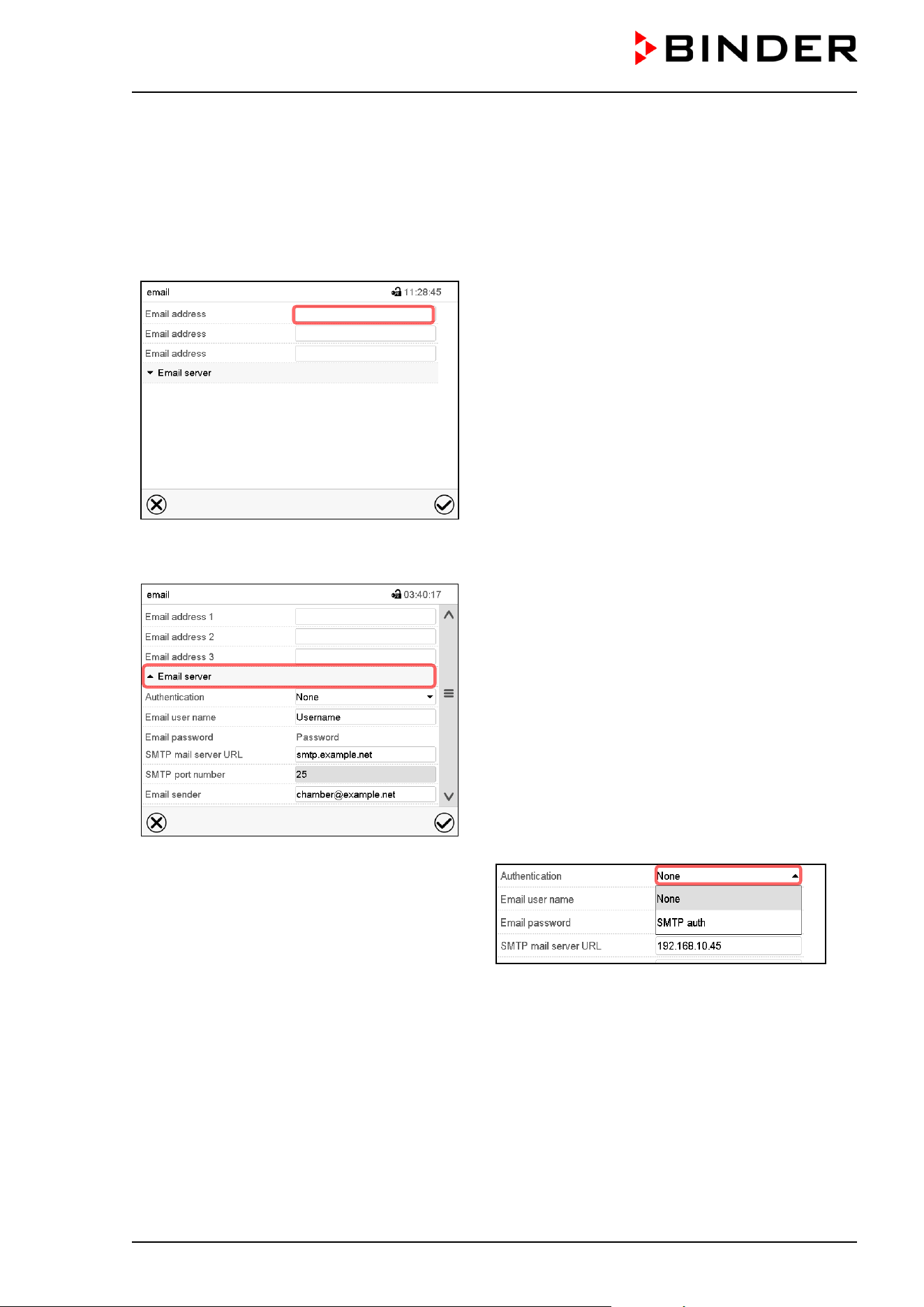
CB / CB-UL, CBF / CBF-UL (E7) 07/2022 Page 128/199
14.5.4 E-Mail
As soon as an alarm was triggered, an e-mail is sent to the configured e-mail address.
Path: Main menu > Settings > Email
E-mail address entry:
“Email” submenu.
Select the desired e-mail address field and enter the
e-mail address. You can use the Keybord change
icon for entry. Confirm entry with Confirm icon.
E-mail server settings:
“Email” submenu.
Select the field “Email server” to access the settings
• In the field “Authentication” select the desired
setting “None” or “SMTP” auth“.
With the setting “SMTP auth”, you can enter a
password under “Email password”.
• Select the field “Email user name” and enter the desired user name. Confirm entry with Confirm icon.
• Select the field “SMTP mail server URL” and enter the SMPT mail server URL. Confirm entry with
Confirm icon.
• Select the field “SMTP port number” and enter the desired port number. Standard setting: “25”. Confirm
entry with Confirm icon.
• Select the field “Email sender” and enter the desired Email sender. Confirm entry with Confirm icon.
After completing the settings, press the Confirm icon to take over the entries and exit the menu, or press
the Close icon to exit the menu without taking over the entries.
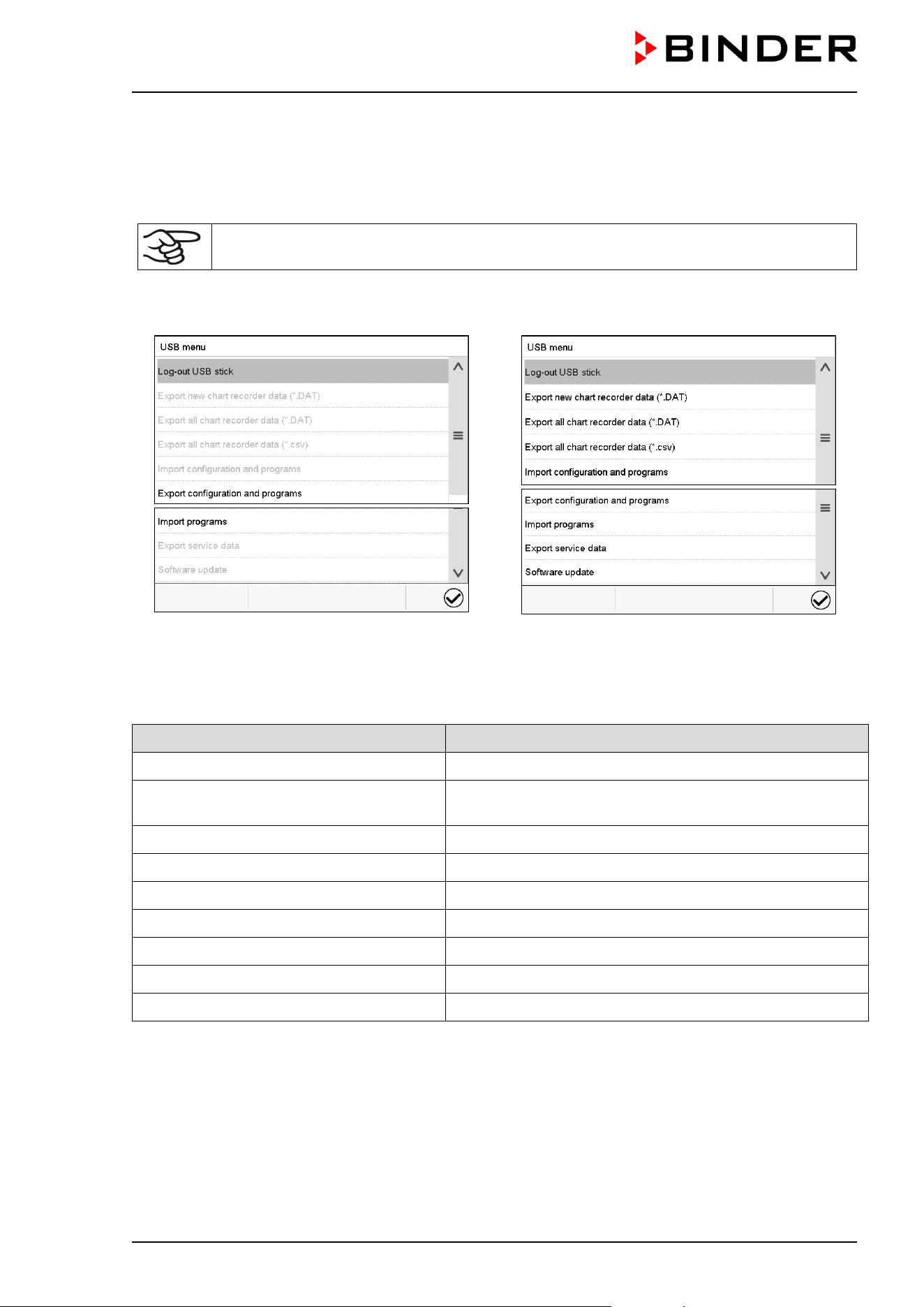
CB / CB-UL, CBF / CBF-UL (E7) 07/2022 Page 129/199
14.6 USB menu: Data transfer via USB interface
The USB port is located in the instrument box.
When you insert a USB-stick, the “USB” menu opens.
The USB stick must be formatted with FAT32 and have at least 8GB of memory.
Depending on the user’s authorization level, different functions (highlighted in black) are available for the
logged-in user.
Available functions
with “User” authorization level
Available functions
with “Admin” authorization level
Function Explanation
Log-out USB stick Log-out USB stick bevor pulling it
Export new chart recorder data (*.DAT)
Export chart recorder data, which have been added since
last export, in .dat format
Export all chart recorder data (*.DAT) Export all chart recorder data in .dat format
Export all chart recorder data (*.csv) Export all chart recorder data in .csv format
Import configuration and programs Import configuration and timer / time / week programs
Export configuration and programs Export configuration and timer / time / week programs
Import programs Import timer / time / week programs
Export service data Export service data
Software update Controller firmware update
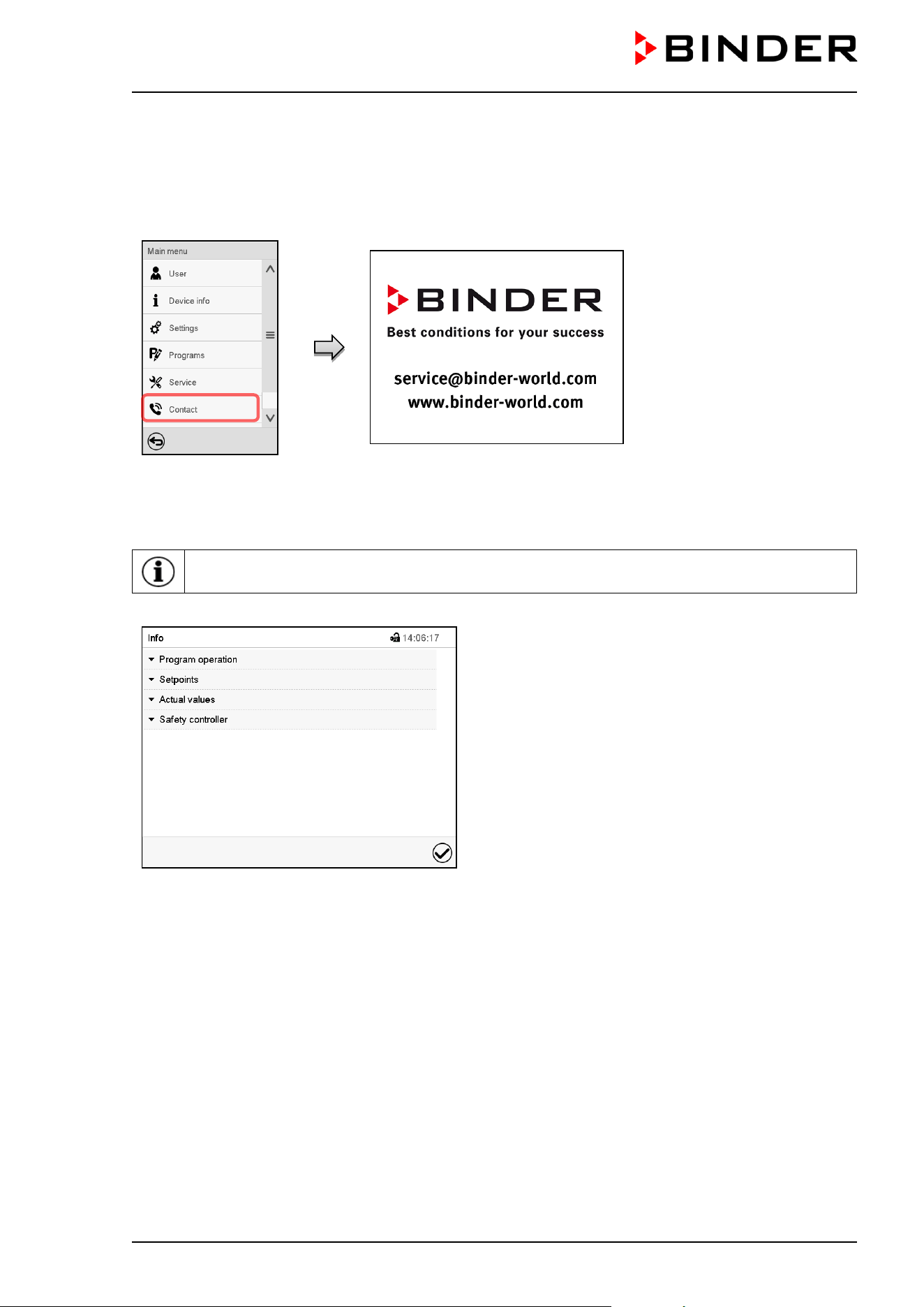
CB / CB-UL, CBF / CBF-UL (E7) 07/2022 Page 130/199
15. General information
15.1 Service contact page
Path: Main menu > Contact
15.2 Current operating parameters
Press the Information icon to access the “Info” menu from Normal display.
“Info” menu.
Select the desired information.
• Select “Program operation” to see information on a currently running program.
• Select “Setpoints“ to see information on the entered setpoints and operation lines.
• Select “Actual values” to see information on the current actual values.
• Select “Safety controller” to see information on the safety controller status.
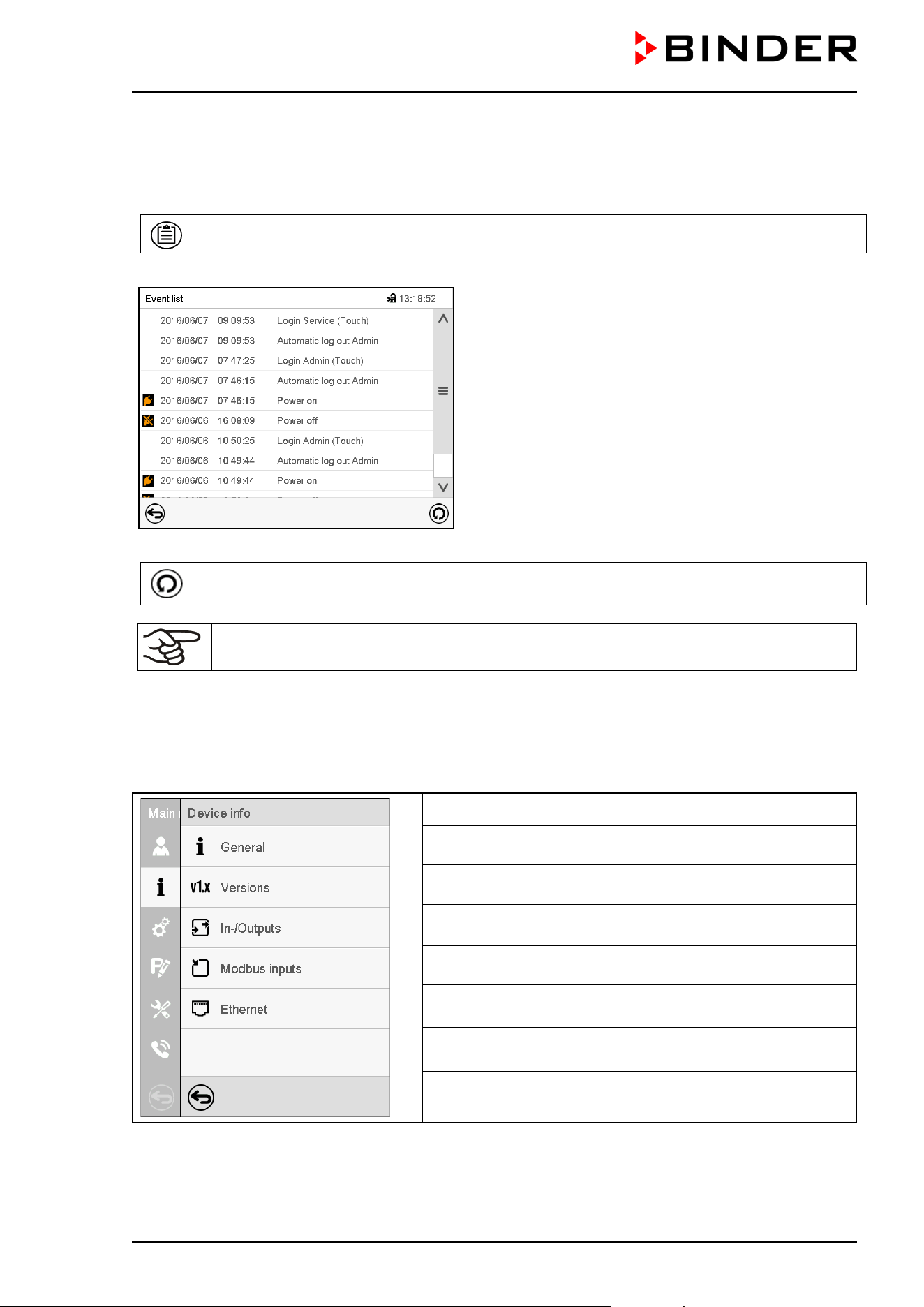
CB / CB-UL, CBF / CBF-UL (E7) 07/2022 Page 131/199
15.3 Event list
The “Event list” displays status information and errors of the current day. It enables to view the last 100
events or defective conditions of the chamber.
Press the Event list icon to access the event list from Normal display.
Event list
Press the Update icon to update the event list.
Attention: Following a modification of the language setting (chap. 14.1) or the storage
interval of the chart recorder (chap. 16.2) the Event list is cleared.
15.4 Technical chamber information
Path: Main menu > Device info
Chamber name and setup
Versions of CPU, I/O module and safety
controller
for BINDER
Service
Information on digital and analog inputs
and outputs and phase angle outputs
for BINDER
Service
Information on modbus analog and digital
inputs
for BINDER
Service
Information on Ethernet connection, MAC
address display
chap. 14.5.2
Back to main menu
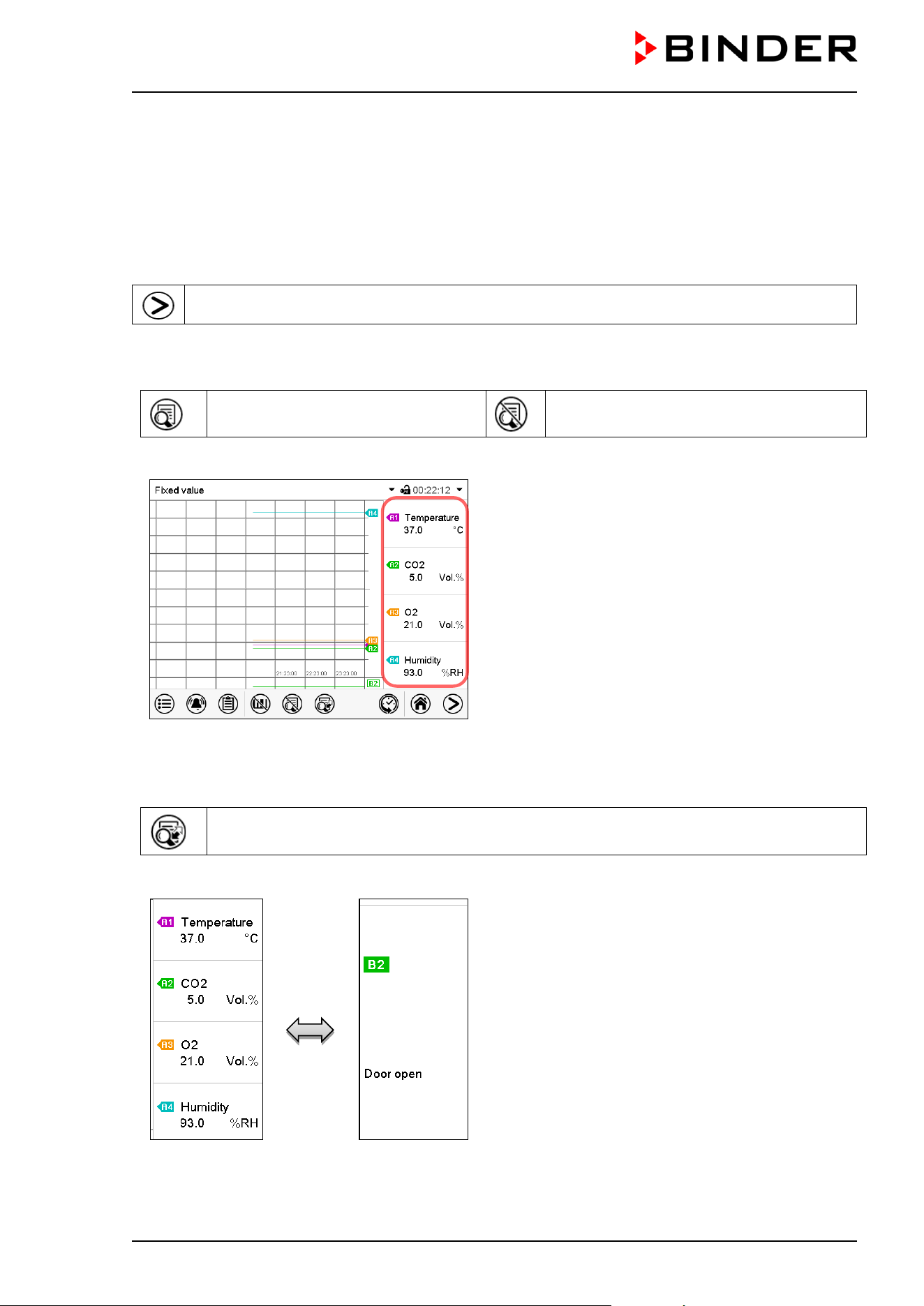
CB / CB-UL, CBF / CBF-UL (E7) 07/2022 Page 132/199
16. Chart recorder display
This view offers graphic representation of the measurement course. Data representation imitates a chart
recorder and allows recalling any set of measured data at any point of time taken from the recorded period.
16.1 Views
Press the Change view icon to access the pen recorder display.
16.1.1 Show and hide legend
Show legend
Hide legend
Press the Show legend icon to display the legend on the right side of the display
Legend shown on the right side of the display
16.1.2 Switch between legend pages
Switch legend
Press the Switch legend icon to switch between the legend pages
1
st
page
2
nd
page
Switching between the legend pages
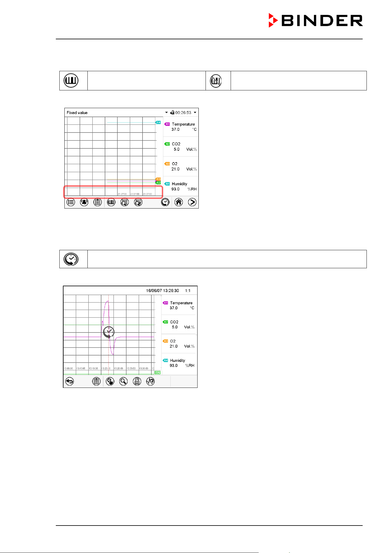
CB / CB-UL, CBF / CBF-UL (E7) 07/2022 Page 133/199
16.1.3 Show and hide specific indications
Show indications
Hide indications
Press the Show indications icon to display the indication “Door open” (B2).
Indication “Door open” displayed (example: 1
st
page).
16.1.4 History display
History display
Press the History display icon to change to the history display.
History display.
The chart recorder is paused. Data recording
continues in the background.
Move the central red line by tapping and holding to
the desired position.
The legend at the right side shows the values of the
current line position.
Then further icons appear:
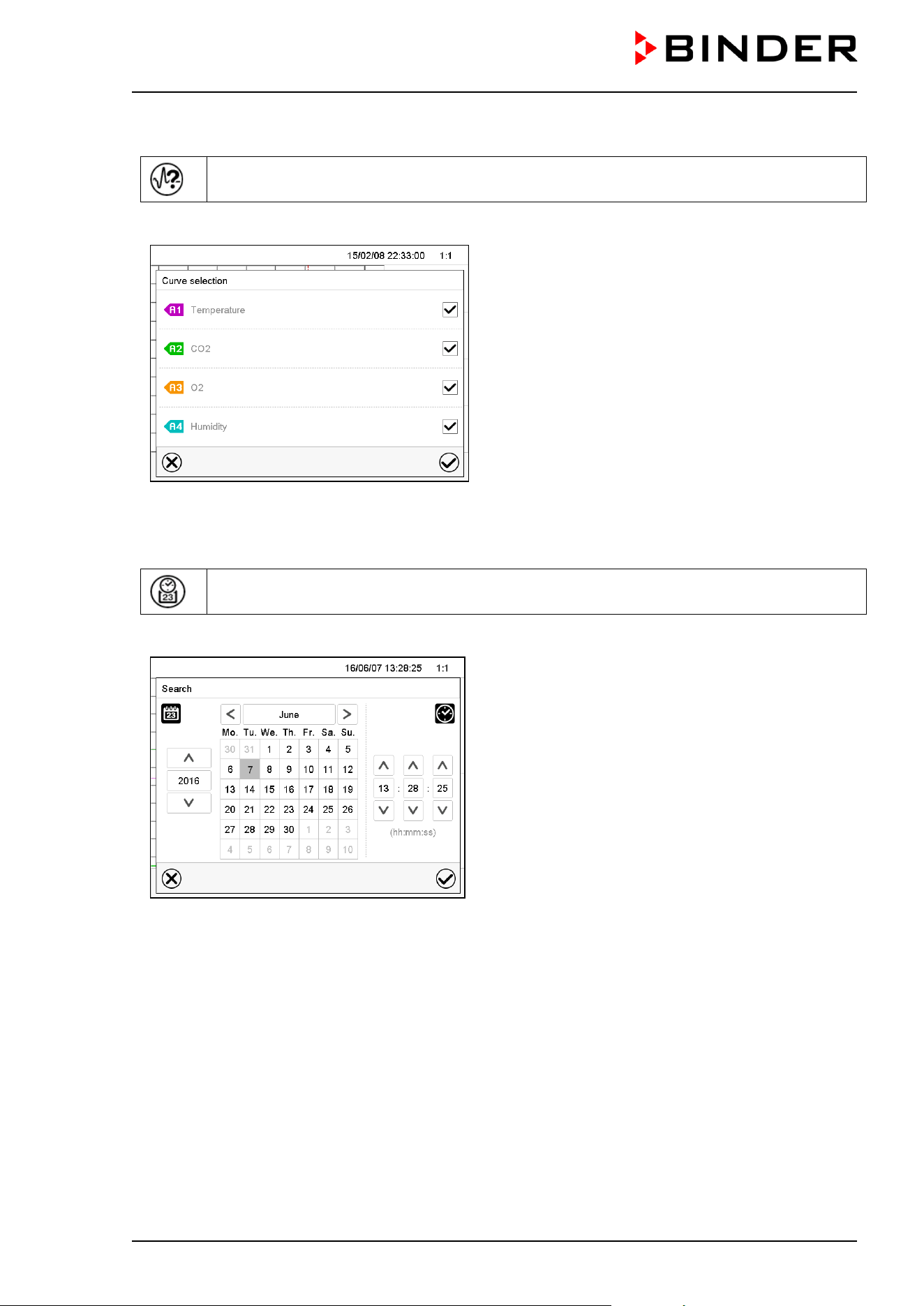
CB / CB-UL, CBF / CBF-UL (E7) 07/2022 Page 134/199
History display: Curve selection
Curve selection
Press the Curve selection icon to access the “Curve selection” submenu.
“Curve selection” submenu.
Select the curves to be displayed by checking the
checkbox of the corresponding parameter. Press the
Confirm icon
History display: Search the required instant
Search
Press the Search icon to access the “Search” submenu.
“Search” submenu.
Select the required instant by entering its date and
time and press the Confirm icon
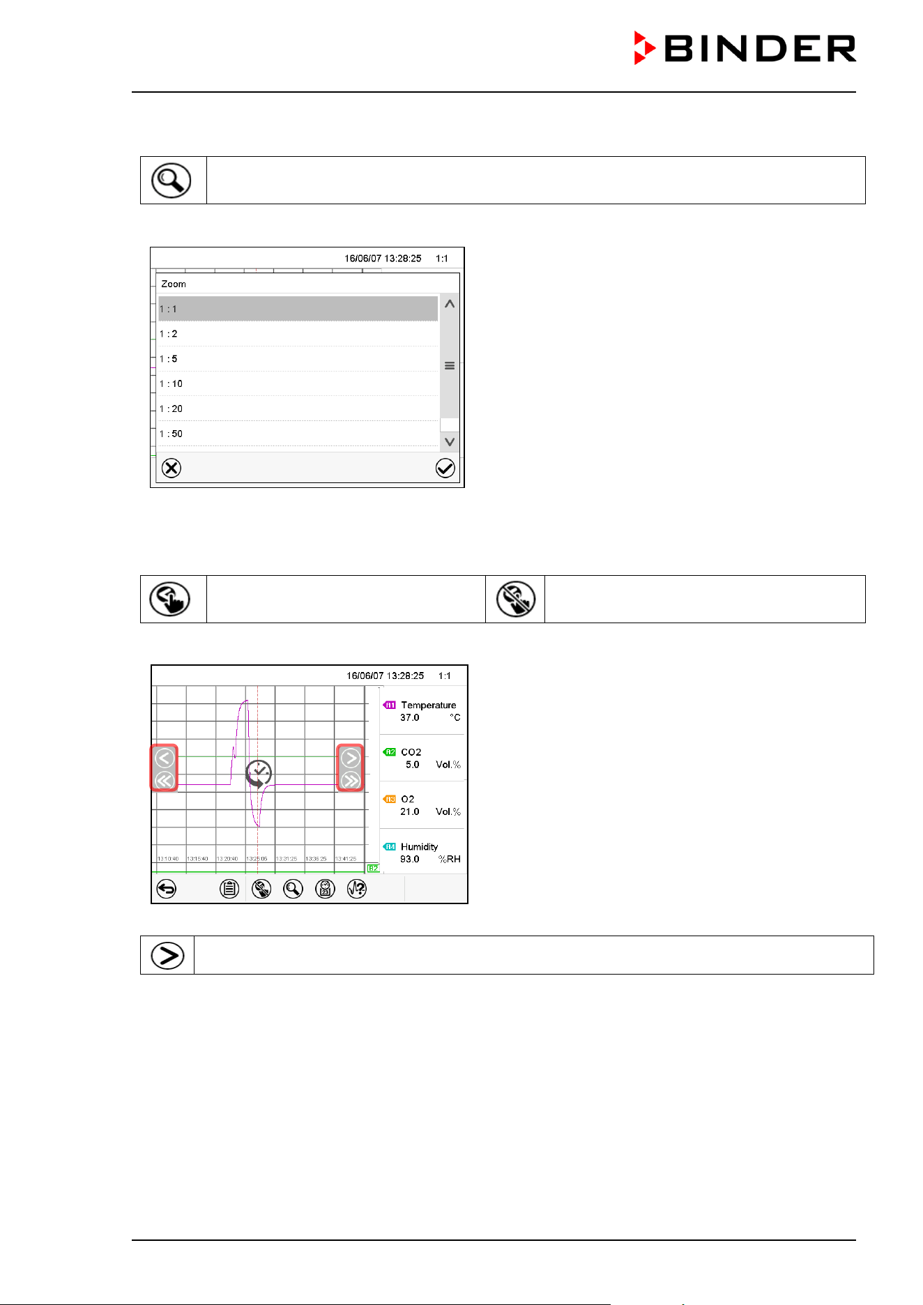
CB / CB-UL, CBF / CBF-UL (E7) 07/2022 Page 135/199
History display: Zoom function
Zoom
Press the Zoom icon to access the “Zoom” submenu.
“Zoom” submenu.
Select the zoom factor and press the Confirm icon
History display: Show and hide scroll buttons to scroll to an instant
Show scroll buttons
Hide scroll buttons
Press the Show scroll buttons icon to access the “Page selection” submenu.
“Page selection” submenu.
Scroll buttons are shown on the left and on the right.
Use them to move along the timeline.
Press the Change view icon to return from the pen recorder display to Normal Display.
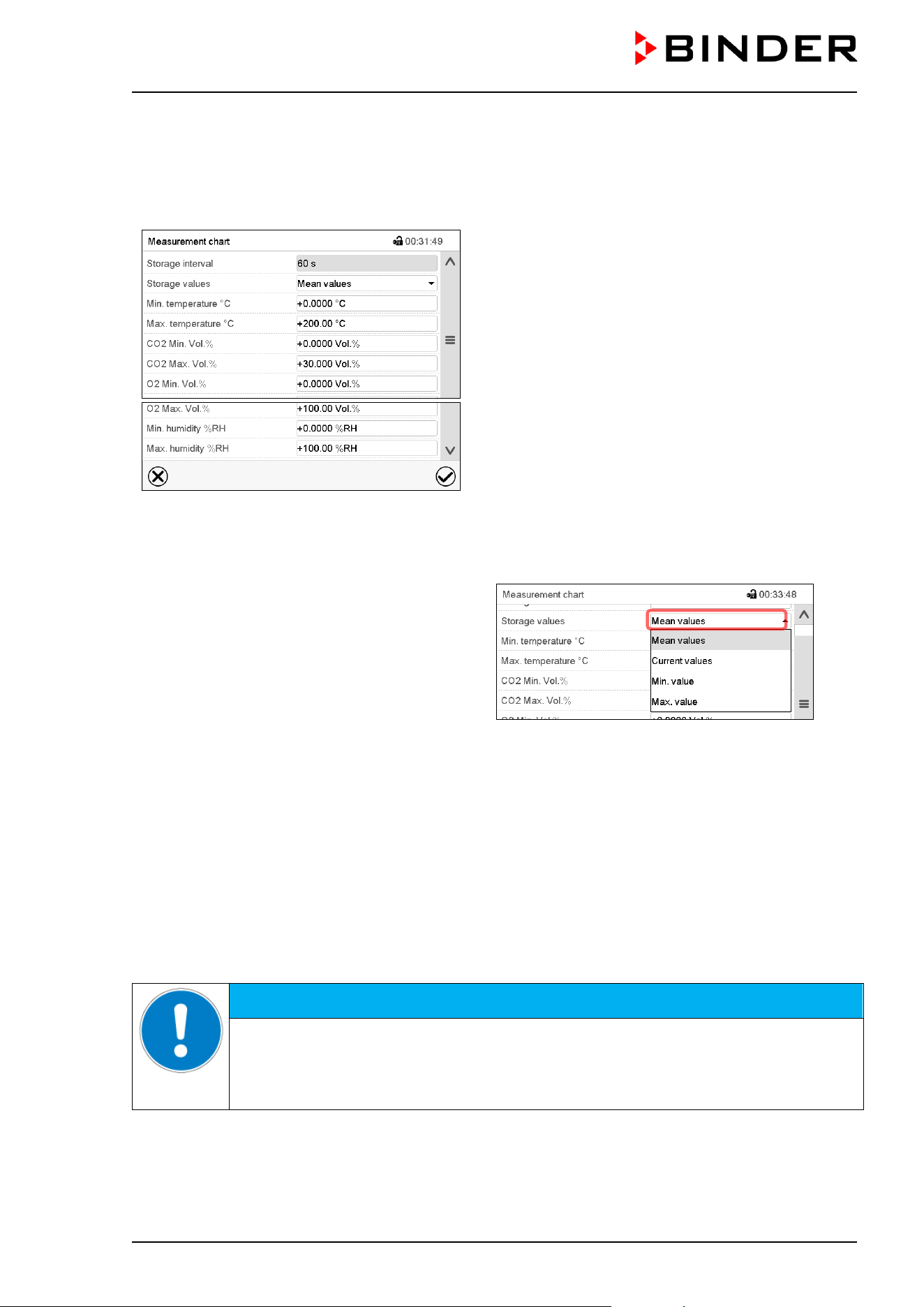
CB / CB-UL, CBF / CBF-UL (E7) 07/2022 Page 136/199
16.2 Setting the parameters
This menu allows setting the storage interval, the type of values to be shown and the scaling of the charts.
Path: Main menu > Settings > Measurement chart
“Measurement chart” submenu.
• Select the field “Storage interval” and enter the desired storage interval. Confirm entry with Confirm icon.
The available presentation depends on the pre-selected storage rate. Factory setting: 60 seconds. This
means the higher the storage rate, the more precisely but shorter the data representation will be.
• In the field “Storage values” select the desired
value type to be displayed.
• For scaling the representation select the desired minimum and maximum temperature, CO
2
/ O
2
or
humidity value and enter the desired values. Confirm each entry with Confirm icon.
Display ranges:
• Temperature: 0 °C up to 200 °C
• CO
2
: 0 Vol.-% up to 100% Vol.-%.
• O
2
: 0 Vol.-% up to 100% Vol.-%.
• Humidity: 0% r.h. up to 100% r.h.
Setting the storage rate or rescaling (minimum and/or maximum) will clear the measured-value memory
and the event list.
NOTICE
Danger of information loss when setting the storage rate or rescaling.
Data loss of measured-value memory and event list.
Change the storage rate or scaling ONLY if the previously registered data is no longer
needed.
After completing the settings, press the Confirm icon to take over the entries and exit the menu, or press
the Close icon to exit the menu without taking over the entries.
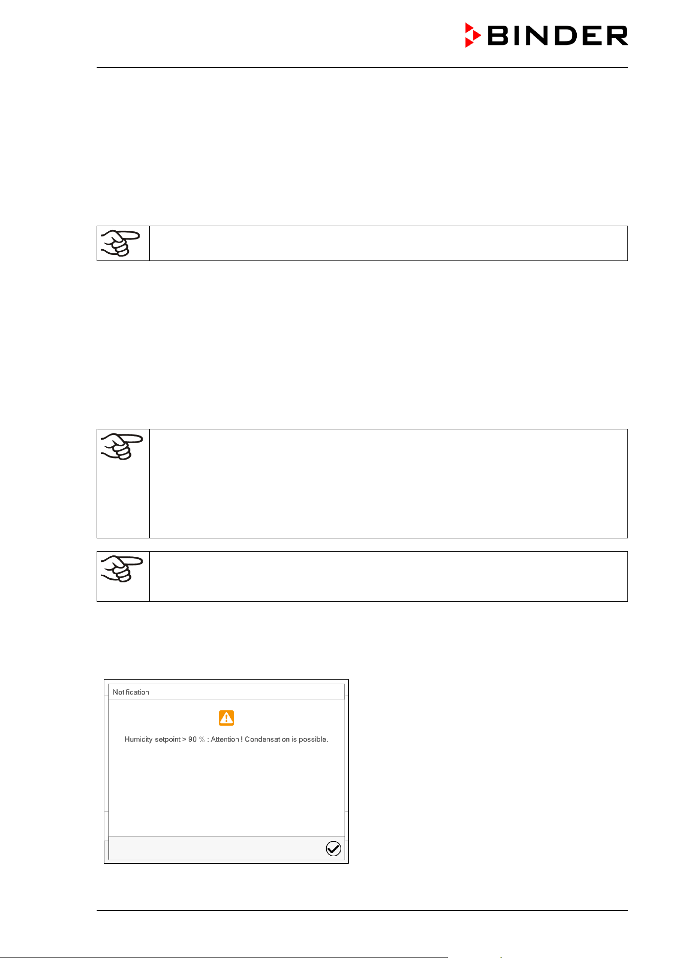
CB / CB-UL, CBF / CBF-UL (E7) 07/2022 Page 137/199
17. CBF / CBF-UL: Humidification system
The chamber is equipped with a capacitive humidity sensor. This results in a control accuracy of up to +/-
3 % r.h. of the set point.
You can turn humidity control on or off in the controller (chap. 6.7).
With humidity control turned off, the humidification module cools down. After activation it will take up to 10
minutes until the humidification function is fully available again. This setting is required when operating the
chamber with the Permadry water pan in order to avoid humidity alarms.
Heat emission of electrical devices connected inside the chamber may modify the
temperature and humidity range.
The chambers are equipped with a door heating system to avoid condensation in the door area.
17.1 Function of the humidifying system
The humidifying system is located in the humidity generation module. In a cylindrical container with a
volume of approx. 0,07 liters an electrical resistance heating evaporates water. The water content is kept
close to the boiling point, and thus steam can be immediately generated in sufficient quantity for rapid
humidity increases or for compensation of humidity losses, e.g. by door openings.
Freshwater is supplied by manually filling a freshwater bag. A peristaltic pump transports the water to the
humidification module via a silicone tube.
In order to ensure accurate humidifying, observe the following points with regard to
the freshwater supply:
• Water type: deionized (demineralized) water
• To ensure humidification during 24 hours even at high humidity set-points, we recommend
filling the freshwater bag at the end of each day.
• Water intake temperature NOT below +5 °C / 41 °F and not exceeding 40 °C / 104 °F.
BINDER GmbH is NOT responsible for the water quality provided by the customer.
Any problems and malfunctions that might arise following use of water of deviating quality is
excluded from liability by BINDER GmbH.
The humidity system is functional only if the freshwater bag is sufficiently filled. Check the filling level daily.
The water reserve is sufficient for one up to two weeks, depending on the humidity demand (set humidity
set-point, number of door openings).
For error indications concerning water supply and humidity system, see chap. 11 and 22.6.
When entering a humidity setpoint value > 90 %
r.h. a message window appears, indicating that
condensation is possible.
Press the Confirm icon.
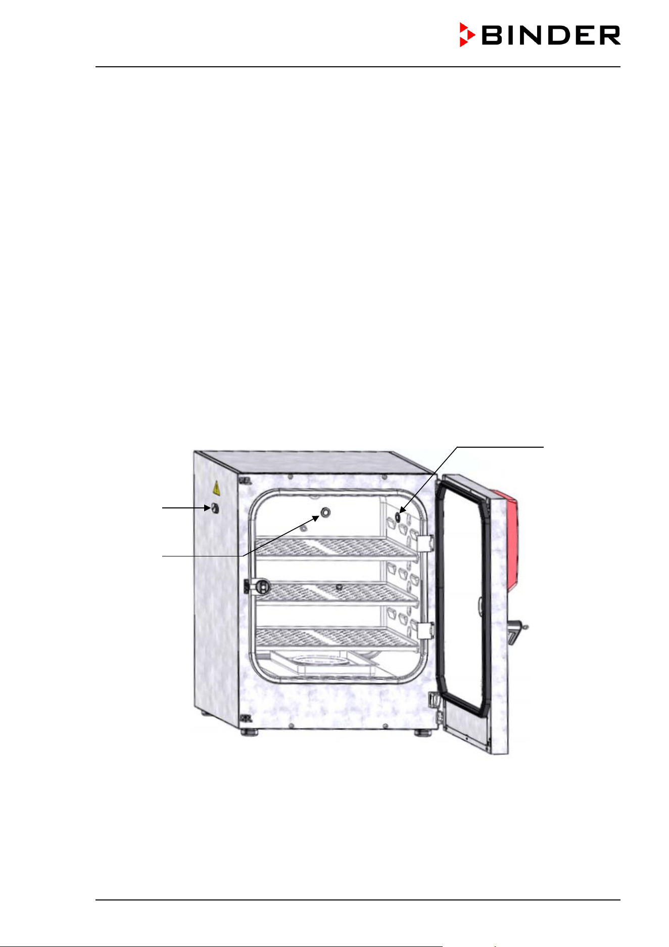
CB / CB-UL, CBF / CBF-UL (E7) 07/2022 Page 138/199
17.2 Function of the dehumidifying system
To reduce the humidity, ambient air is sucked in through a gas fine filter (sterile filter). As a result, the air in
the interior is diluted with the air from outside. The air tube for inlet of the ambient air is located in the upper
right corner in the recess for the freshwater bag. We recommend replacing the sterile filter on this tube
about once a month. To replace the sterile filter, see chap. 22.2.3.
18. Options
18.1 APT-COM™ 4 Multi Management Software (option)
The chamber is regularly equipped with an Ethernet interface (5) that can connect the BINDER APT-COM™
4 Multi Management Software. The MAC Address is indicated in the “Device info” controller menu (chap.
14.5.2.2). The actual values of temperature, CO
2
, O
2
(chamber with O
2
control) and humidity (CBF / CBF-
UL) are given at adjustable intervals. Programming can be performed graphically via PC. Up to 100
chambers can be cross-linked. For further information on networking please refer to the operating manual
of the BINDER communication software APT-COM™ 4.
18.2 Silicone access ports 30 mm / 1.18 in, closable from both sides with silicon
plugs (option)
(a)
(b)
(c)
Figure 41: Positions of the optional silicon access ports left (a), rear (b), and right (c)
A warning sticker is located above each access port on the outside of the incubator.
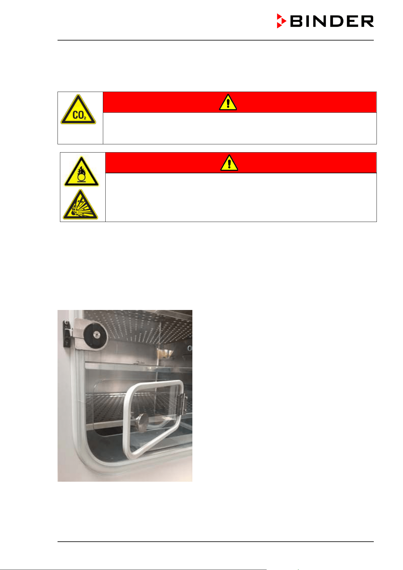
CB / CB-UL, CBF / CBF-UL (E7) 07/2022 Page 139/199
When operating a chamber with silicon access ports, both silicon plugs must tightly close the access ports.
If the plugs are inserted in a not-gastight manner, or if plugs are missing, CO
2
/ O
2
/ N
2
gas (chamber with
O
2
control) may escape into the environment. The CO
2
control and the O
2
control (chamber with O
2
control)
only turn off when the chamber door is opened.
DANGER
Danger of suffocation and poisoning by high concentration of CO
2
(> 4 Vol.-%).
Death by suffocation.
Tightly close each access port with two plugs during operation.
DANGER
Danger of fire and explosion through contact of combustible materials with O
2
with high concentration of O
2
(> 21 % O
2
).
Serious injury or death from burns and / or explosion pressure.
Tightly close each access port with two plugs during operation.
18.3 Quick sample access (option)
The quick sample access option provides easy access to the sample chamber through a small window in
the glass inner door. This is a useful feature in applications with short incubation times. The window
measures 13 x 25 cm and is located in the bottom corner of the glass inner door.
This quick method of accessing samples is available for both the standard door hinge on the right and the
door hinge on the left.
Figure 42: Glass door (detail, example door hinge on the right) with Quick sample access option
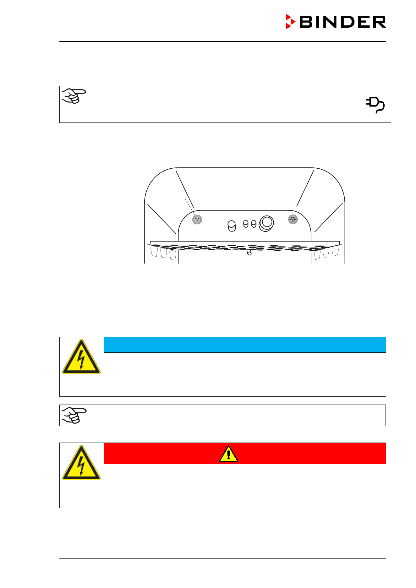
CB / CB-UL, CBF / CBF-UL (E7) 07/2022 Page 140/199
18.4 Interior socket 230V (option, available via BINDER INDIVIDUAL Customized
Solutions)
The interior socket is activated and deactivated in the controller via the switching
state of an operation line (chap. 7.3, 9.7.3, 10.6.5). When the interior socket is
activated, the notification “Interior socket“ is shown highlighted in black next to the
information icon in the screen header in Normal display (chap. 11.1.1)
The interior socket (G) is located at the upper left corner on the rear wall of the inner chamber. It is closed
with a waterproof lid. The interior socket is suitable to supply electrical devices inside the chamber with
230V AC voltage.
Figure 43: Position of the interior socket 230 V
(G) Interior socket
The maximum head load must not exceed a capacity of 20 W.
NOTICE
Danger of damage when exceeding the setpoint temperature.
Damage to the cultures.
∅ Do NOT exceed the maximum head load of 20 W.
∅ Do NOT connect equipment with a nominal capacity > 20 W.
Heat emission of electrical devices connected inside the CO
2
incubator may modify the
temperature and humidity range.
The maximum load must not exceed 3 Amp.
DANGER
Electrical hazard through overload of contacts.
Deadly electric shock. Damage to contacts and connection socket.
∅ Do NOT exceed the maximum load of 3 A.
∅ Do NOT connect any devices with a nominal current > 3 A.
(G)
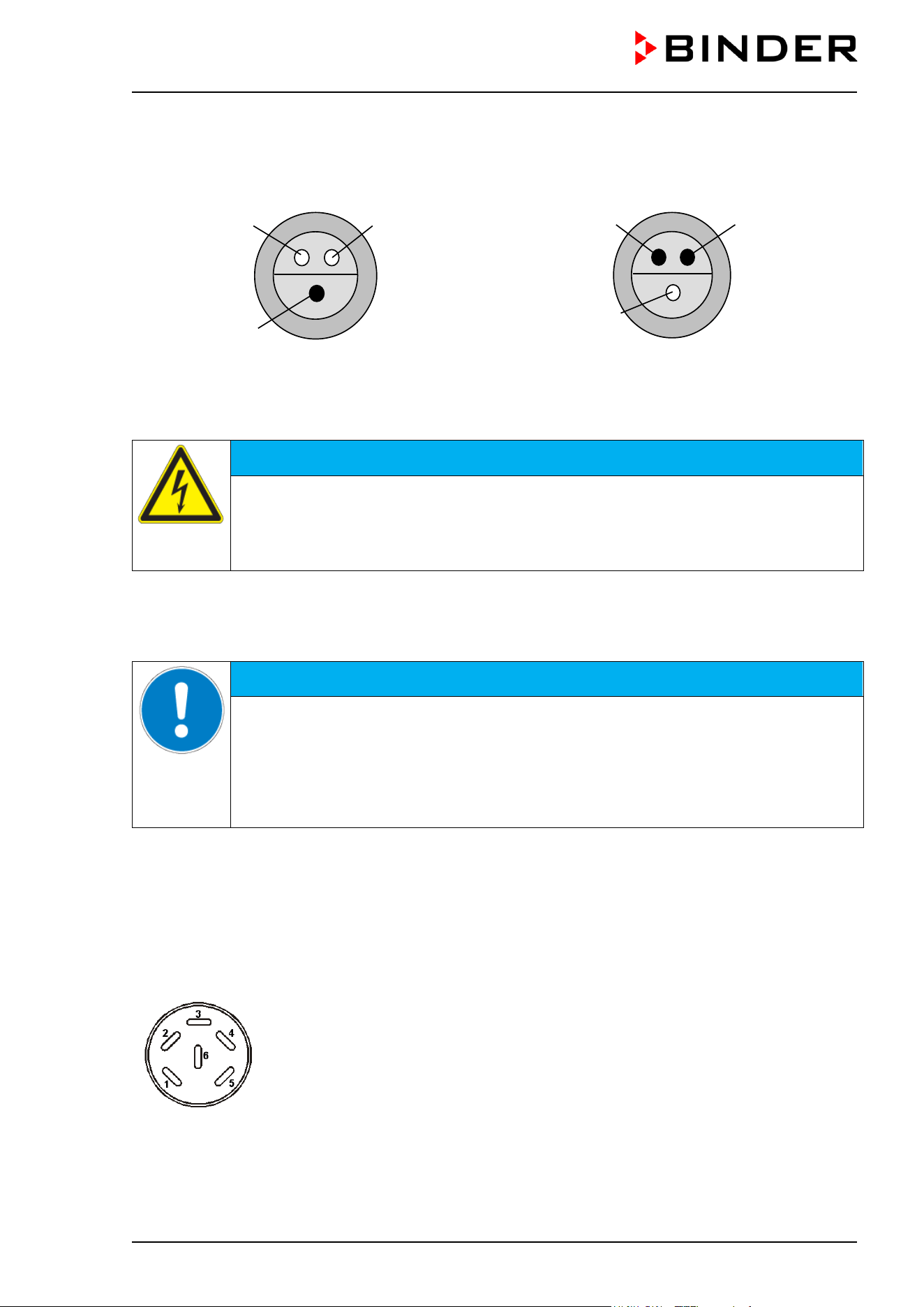
CB / CB-UL, CBF / CBF-UL (E7) 07/2022 Page 141/199
The interior socket’s voltage is turned off at the chamber controller via operation line (chap. 7.3, 9.7.3,
10.6.5).
Turning off the chamber at the main power switch also switches the interior socket voltage-free.
Figure 44: Interior socket (G) (front view) Figure 45: Supplied plug (front view)
Electrical data socket and plug: IP system of protection 65, 230 V 1N ~ 50-60 Hz
NOTICE
Risk of short circuit caused by penetration of moisture into the socket.
Damage to the chamber.
Use the supplied plug only (IP protection type 65).
If the socket is not used, close it with the waterproof lid.
When inserting a heat load into the inner chamber by introducing electrical devices such as shakers or
rollers, the ambient temperature of the incubator must not exceed 25 °C / 77 °F. Otherwise, temperature
control to 37 °C / 98.6°F cannot be assured. When operating electrical devices inside the incubator, always
check the desired incubation temperature before introducing any cells.
NOTICE
Danger of excessive inner temperature > 37 °C / 98.6 °F when operating electrical
devices inside the incubator.
Damage to the cell cultures.
Make sure that the ambient temperature is ≤ 25 °C / 77 °F w
hen operating electrical
devices inside the incubator:.
Check the temperature observation before introducing any cells.
18.5 Analog outputs for temperature and CO
2
(option)
With this option, the chamber is equipped with analog outputs 4-20 mA for temperature and CO
2
. These
outputs allow transmitting data to external data registration systems or devices.
The connection is realized as a DIN socket (4) on the chamber rear. A suitable DIN plug is enclosed.
ANALOG OUTPUT 4-20 mA DC
PIN 1: Temperature +
PIN 2: Temperature -
PIN 3: CO
2
+
PIN 4: CO
2
-
CO
2
range: 0 vol.-% up to 20 vol.-%
Temperature range: 0 °C / 32°F up to +200 °C / 392°F
Figure 46: Pin configuration of the DIN socket (4) on the chamber rear
Pin 2 (L)
Pin 1 (N)
Pin 3 (PE)
Pin 2 (L)
Pin 1 (N)
Pin 3 (PE)
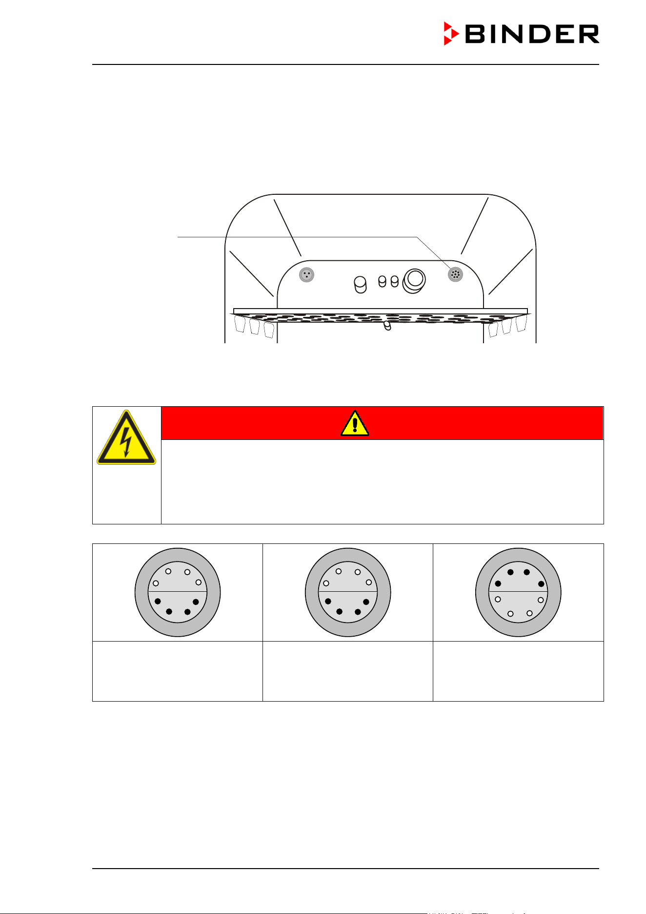
CB / CB-UL, CBF / CBF-UL (E7) 07/2022 Page 142/199
18.6 Access port for extra-low voltage (option)
The access port (B) (8-pin) for extra-low voltage (ELV) consists of a LEMO socket (which can be covered)
and a LEMO connector. It is suitable to connect two electrical devices, one inside and one outside the
incubator. You can use it e.g. for devices with a monitoring and control part remaining outside the incubator,
whereas its mechanical component like roller or shaker systems is located inside the chamber.
Figure 47: Position of the access port for extra-low voltage
Maximum power rating 24V AC/DC 2Amp.
DANGER
Electrical hazard through overload of contacts.
Deadly electric shock. Damage to contacts and connection socket.
∅ Do NOT exceed the maximum load of 24V AC/DC 2Amp.
∅ Do NOT connect any devices with a nominal current > 2 Amp.
∅ Do NOT connect any devices with a nominal voltage > 24 V DC.
On chamber rear:
Exterior Lemo socket (2) on the
rear of the chamber
Interior:
LEMO socket (B) located at the
upper right corner of the rear
wall of the inner chamber
Supplied LEMO connector:
on external and internal side
Figure 48: Pin allocation (front view) of the Lemo sockets and plug
When introducing a heat load into the inner chamber by inserting electrical devices like shakers or rollers,
the ambient temperature of the incubator must not exceed 25 °C / 77°F. Otherwise, temperature control to
37 °C / 98.6°F cannot be assured. When operating electrical devices inside the incubator, always check
the desired incubation temperature before introducing in any cells.
3
4
6
7
5
2
1
8
3
4
6
7
5
2
1
8
2
1
7
6
8
3
4
5
(B)
CB / CB-UL, CBF / CBF-UL (E7) 07/2022 Page 143/199
NOTICE
Danger of excessive inner temperature > 37 °C / 98.6 °F when operating electrical
devices inside the incubator.
Damage to the cell cultures.
Make sure that the ambient temperature is ≤ 25 °C / 77 °F
when operating electrical
devices inside the incubator:.
Check the temperature observation before introducing any cells.
18.7 BINDER Gas Supply Service – External bottle changer for CO
2
, N
2
or O
2
(option)
The external bottle changer permits automatic switching to a second gas cylinder as soon as the first
cylinder is empty. It can be used for a maximum of two CB chambers.
Instructions 7001-0196 delivered with the external bottle changer (Art. no. 8012-0408)
describe its installation and operation.
18.8 Stands
18.8.1 Flat stacking adapter for thermally decoupled stacking (option)
We recommend not stacking the incubators directly on top of one another in order to avoid transmission of
shocks and vibrations from one chamber to the other. This could happen e.g. while opening or closing the
door, cleaning, charging and discharging the chamber. BINDER offers a flat stacking adapter for the safe
stacking of two BINDER CO
2
-incubators.
The stacking adapter ensures that the set incubation parameters are precisely maintained also during
sterilization of the other chamber (chap. 21.3) by thermal decoupling.
Art. No. 9051-0038 for incubator size 56, Art. No. 9051-0035 for incubator size 170, Art. No. 9051-0039 for
incubator size 260.
The mounting instructions 7001-0294 delivered with the stacking adapter describe its
installation.
18.8.2 Stacking stand on castors with castors lockable by breaks (option)
We recommend not stacking the incubators directly on top of one another in order to avoid transmission of
shocks and vibrations from one chamber to the other. This could happen e.g. while opening or closing the
door, cleaning, charging and discharging the chamber. BINDER offers stable, vibration-free stands with
castors (2 lockable by brakes) for the safe stacking of two BINDER CO
2
-incubators.
The stacking stand ensures that the set incubation parameters are precisely maintained also during
sterilization of the other chamber in the same stacking stand (chap. 21.3) by thermal decoupling.
Using the stacking stand offers more advantages: You can pull the lower chamber forward separately (e.g.,
for access to the rear), and not have to place it directly on the floor (important for sanitary purpose).
Art. No. 9051-0020 for incubator size 170, Art. No. 9051-0041 for incubator size 260.
CB / CB-UL, CBF / CBF-UL (E7) 07/2022 Page 144/199
The mounting instructions 7001-0194 delivered with the stacking stand describe its
installation.
18.8.3 Base on castors (option)
In order to obtain easy access to the chamber, for safe placement and leveling of a BINDER CO₂ incubator,
and to avoid contamination of the chamber caused by soil pollution, BINDER recommends using the base
on castors.
Art. No. 9051-0043 for incubator size 56, Art. No. 9051-0028 for incubator size 170, Art. No. 9051-0044 for
incubator size 260.
The mounting instructions 7001-0147 delivered with the base on castors describe its
installation.
18.9 Water supply sets (optional for CBF / CBF-UL)
18.9.1 Tubular bag set (option)
For the water supply via freshwater bag (standard), a set with 12 tubular bags (annual demand) is available.
The bag set includes all necessary connecting parts.
For details please refer to chap. 4.5.2.
18.9.2 Humidification water set (option)
For the optional water supply via prefilled water bottle, a humidification water set with 10 prefilled one-liter
bottles (annual demand) is available. It includes all necessary connecting parts. For details please refer to
chap. 4.5.3.
By using the humidification water set you will achieve unsurpassed contamination safety of your samples
in the BINDER CO
2
incubator CBF / CBF-UL.
18.9.3 Water container set (option)
The fresh water can, which is placed in an included magnetic can holder on the left chamber side, serves
to supply one or several chambers with freshwater for humidification.
The water container set includes all necessary connecting parts. For details please refer to chap. 4.5.4.
19. Reference measurements
Reference measurements of the temperature, CO
2
, O
2
(chamber with O
2
control), and humidity can be
performed via the silicone measuring port (N) located on the inner glass door. Reference temperature
measurements always take place under equilibrated conditions with both doors closed.
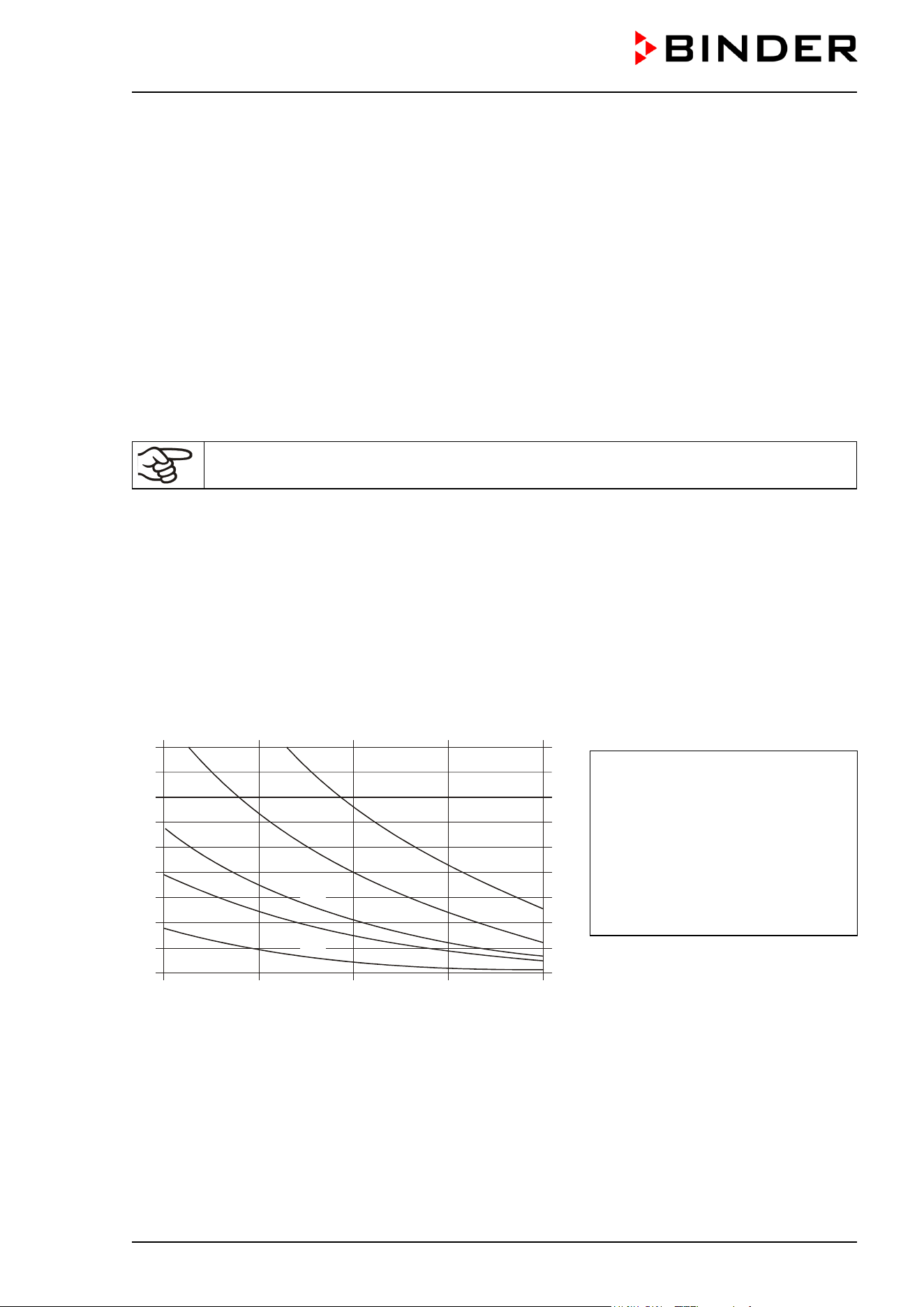
CB / CB-UL, CBF / CBF-UL (E7) 07/2022 Page 145/199
19.1 CO
2
reference measuring
There are three possibilities to perform CO
2
test measurements between the recommended annual
maintenance procedures. To test the CO
2
concentration inside an incubator, see chapters 19.1.1 to 19.1.3.
19.1.1 Measuring CO
2
concentration indirectly via the pH of the cell medium
By using the indirect determination of CO
2
concentration via the pH-value of the nutrient, it is possible to
check the CO
2
concentration inside the chamber. This is a simple method to test the correct CO
2
concentration without any special CO
2
measuring equipment. You need only use an accurate pH indicator
or a pH-measuring electrode, which are standard equipment in cell culture laboratories.
This method is based on the acid base equilibrium of the buffer system in the culture media. NaHCO
3
buffers the common media. From the pH value of the medium, it is possible to conclude its CO
2
concentration. Figure 49 shows the relationship between CO
2
concentration in vol.-% and the pH of different
NaHCO
3
buffered media.
These test systems are not suitable for calibrating the BINDER sensor system.
Recommended procedure:
• Incubate an empty sample with medium for 1/2 day under the same conditions as the cells. You can
perform the incubation in a cell culture cylinder or in a 50 ml Falcon tube with open lid.
• After gassing, remove the empty sample from the incubator and within 5 minutes measure the pH-value
with a glass electrode.
During the measurement, the medium should have the least possible surface contact with the ambient
air, so that the CO
2
can evaporate only slightly. A significant downward movement will happen only after
5 minutes, permitting sufficient time for measurement.
• In addition, you can of course use pH-test strips (pH range 6 to 8, not bleeding).
4
6
8
10
12
14
16
18
2
3,70 g/l NaHCO
3
2,20 g/l NaHCO
3
0,85
g/l NaHCO
3
6.8 7.0
7.2
7.4
7.6
Value pH
Vo l. % C O
2
0,35
g/l NaHCO
3
1,20 g/l NaHCO
3
Trade names of common media:
DMEM
BME
MEM
Medium 199
Mc Coy
F10
F12
NaHCO
3
[g/l]
3.70
2.20
2.20
2.20
2.20
1.20
1.20
Figure 49: Value pH of NaHCO
3
buffered media as a function of the CO
2
concentration:
Example: If a pH of 7.2 is measured in a medium buffered with 2.20 g NaHC0
3
per liter, there must be
8 vol.-% CO
2
surrounding this medium.

CB / CB-UL, CBF / CBF-UL (E7) 07/2022 Page 146/199
19.1.2 Measuring CO
2
directly via chemical indicator tubes
This is a common “do-it-yourself” test for many users. A chemical color reaction in a glass tube shows the
CO
2
concentration. A standardized volume of air from inside the incubator has to be suctioned through this
glass tube to get a quantitative test result. Therefore, use a special hand pump with a standardized suction
volume.
Procedure (example):
All the necessary equipment must be supplied by one manufacturer only and in a defined test system.
Note: These test systems are not very accurate. A typical accuracy is around 10 % of the full-scale value.
These test systems are not suitable for calibrating the BINDER sensor system.
19.1.3 Measuring CO
2
directly with an electronic infrared measuring device
Another possible way of measuring the CO
2
concentration is by electronic sensor systems. Portable
measuring devices are suitable for measuring temperature and CO
2
concentration and can be used both
for reference measurements in certified laboratories, and for service purposes.
19.2 Temperature reference measurement
When performing a temperature reference measurement using an electronic measuring, and temperature
display device, it is important to use a device traceable to an acknowledged standards/calibration institution
(DKD, PTB for Germany) with a valid calibration certificate.
Note: The cable of the sensor must be thin enough to lay it over the door gasket of the incubator without
causing any leakages.
20. Avoiding microbial contamination
The main types of microbial contaminants in cell and tissue culture are bacteria, fungi, yeast, mycoplasma,
and viruses. This chapter gives an overview of potential sources of contamination and precautions and
measures to eliminate them.
20.1 Cells and media
• Primary cultures from the original tissue
• Cells / cell lines from unknown sources or from cell banks: Use only cells of known and tested origin.
Monitoring and routine screening of new cultures.
• Media and sera: Use only sera of known and tested origin (mycoplasma free, e.g., UV or γ radiated).
• Virus suspensions, antibody solutions etc. Use only reagents of known and tested origin.
• Laboratory instruments, media and reagents that were exposed to possible contaminated cultures must
be sterilized / autoclaved / disposed.
• Antibiotics in the cell culture media may prevent bacteria detection: Use antibiotics selectively and
economically.

CB / CB-UL, CBF / CBF-UL (E7) 07/2022 Page 147/199
20.2 Laboratory conditions / equipment around the incubator
Possible sources of contamination in the cell culture lab are airborne germs, lab equipment, building
features, and the lab personnel.
• Keep pipettes and instruments sterile after autoclaving.
• Bio safety cabinets (laminar air flow) should have a minimum of items apart from aspirator tube and
burner. Items shall be positioned within easy reach and separate from each other. Disinfect surfaces
with an alcohol-based disinfectant before and after use, clean the space underneath the bench, and
carry out regular sterility tests of the filters.
• Regular cleaning / disinfection of laboratory equipment such as a centrifuge, microscope, water bath,
refrigerator, and telephone.
• No equipment should be placed on the floor.
• Rough or humid walls are not suitable.
• Identify leaking doors and windows and make them airtight.
• Use air conditioning with special filters.
• Reduce the number of personnel and their movements in the lab by careful positioning all relevant
equipment. For practical reasons, install the chamber close to the laminar air flow bench.
• Regular microbiological monitoring of the cell culture laboratory.
20.3 Working and behavior in the lab
Sources of contamination are often the laboratory personnel themselves (surface germs, oral flora droplet
transfer) and handling the equipment and cultures. We recommend staff training in aseptic techniques,
laboratory safety and good laboratory practice (GLP).
Examples of general rules to reduce the contamination risks
• Reduce hand germ count (wash hands with antimicrobial soap, dry with paper tissues, and rub dry
hands with alcohol-based solution).
• Wear appropriate clothing (work coat, shoes, face mask)
• Keep as few personnel as possible in the cell culture lab.
Examples of sterile working method
• Work "clean-to-dirty", i.e., handle confirmed uncontaminated cells first, unknown or untested cells next,
and lastly, if necessary, cells suspected to be contaminated.
• Perform daily microscopic observations of cultures and specific tests for the bacteria and fungi as part
of a controlled routine. Test cultures for sterility before starting work.
• Keep working surfaces clean. Immediately wipe spilled liquids with alcohol solutions.
• No mouth contact on pipettes.
• Never work on top of open sterile containers.
20.4 Chamber design and equipment of the CO
2
incubator
The design concepts behind the CO
2
incubator considerably reduce the risk of contamination. Among them
are:
Even surfaces for easy manual cleaning
• The inner surfaces are smooth and therefore easy to clean. The inner chamber is deep-drawn from a
single piece, polished (suitable for pharmaceutical work) and has no welds or inaccessible corners.
The hinges and the seal of the inner glass door are glued from the outside, which also aids cleaning of
the inner chamber.

CB / CB-UL, CBF / CBF-UL (E7) 07/2022 Page 148/199
Removable parts for cleaning and autoclaving
• The shelves are easily removed without screws. It is possible to autoclave the shelves. But this is
generally not necessary because they can remain inside the chamber during sterilization.
Door gasket
• The inner door gasket is removable and autoclavable.
Gas fine filter
• The incoming gas used in the operation passes through a fine filter (aseptic filter, filtration efficiency
99.99 %, particle size 0.45 µm) with a high filtration efficiency, which can also filter the smallest particles.
CO
2
measuring system in the inner chamber
• The CO
2
sensor can be hot-air sterilized inside the chamber.
O
2
measuring system in the inner chamber (chamber with O
2
control)
• The O
2
sensor can be hot-air sterilized inside the chamber.
Humidity measuring system in the inner chamber (CBF / CBF-UL)
• The humidity sensor can be hot-air sterilized inside the chamber.
Condensation prevention
• Condensation in the inner chamber represents a particular risk of contamination. The Permadry™
system developed by BINDER is an effective and easy way to ensure high humidity (≥95 % r.h.) inside
the chamber without any condensation forming on the inner surfaces.
Hot air sterilization
• The heating system of the CO
2
incubator permits hot-air auto-sterilization at a setpoint of 180 °C / 356 F.
Thus, the effective sterilization temperature is maintained for at least two hours on all internal surfaces,
resulting in sterilization of the entire inner chamber.
20.5 Handling the CO
2
incubator
Any manipulation of the CO
2
incubator involves some contamination risks, from installation to opening the
doors and regular cleaning.
Installation away from sources of contamination
• Do not place the chamber on the floor or close to windows and doors. Use the optional stand, if
appropriate.
Reduce the periods in which the door is open
• Do not open the door too frequently.
• Placing items in order inside the chamber results in shorter door opening times.
Permadry™ water pan
• Fill the outer pan with distilled, sterilized water (chap. 4.2). Never use ion exchange water; ion
exchangers are propagation sites for bacteria.
• Clean and refill the pans 2 to 3 times a week. For evacuation, remove the Permadry™ water pan. It is
autoclavable.
• If desired, you can add microbiologically inhibiting substances as copper chips, copper sulfate or
ethylene diamine tetra-vinegar acid (EDTA) in a concentration of 1 to 5 mmol/l.
Avoiding condensation caused by ambient conditions
Ambient room conditions have an effect on condensation inside the chamber, which can be caused by
insufficient wall clearances, preventing even dissipation of heat, air movement or direct sunlight. If the
temperature distribution inside the chamber becomes uneven, condensation may form on the cooler
surfaces.
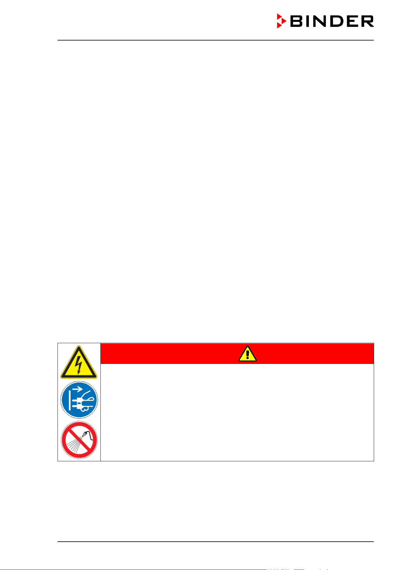
CB / CB-UL, CBF / CBF-UL (E7) 07/2022 Page 149/199
• Maintain distances from the wall: rear 100 mm / 3.94 in, sides 50 mm / 1.97 in
• Do not place the chamber in front of a window. No direct sunlight. No air movement.
• Permissible ambient temperature range for operation: +18 °C / 64.4°F to +30 °C / 86°F.
Ideal ambient temperature: by at least 7 °C / 12.6 °F below the intended working temperature. E.g.,
working temperature 37 °C / 98.6 °F = ambient temperature 30 °C / 86 °F and less.
• The chamber should be calibrated / precisely adjusted.
• Let BINDER Service adjust the setting of the door heating in reaction to critical ambient conditions.
Regular cleaning, decontamination and sterilization
• Clean the shelves, glass door, gaskets, and inner chamber weekly (for cleaning see chap. 21.1, for
decontamination see chap. 21.2. You can clean the shelves in a laboratory dishwasher and, if needed,
individually autoclave them.
• Regularly use the hot air sterilization function (chap. 21.3) following cleaning. The shelves and the
emptied water pan can remain inside the chamber during this operation.
• Have replaced the CO
2
sterile filter (gas fine filter) once or twice a year.
What to do in case of contamination?
• Throw away / autoclave contaminated cultures.
• Carefully inspect cultures that seem to be uncontaminated.
• Clean the chamber as described. Wipe the inner chamber and the doors with a disinfectant and allow
drying. Autoclave the shelves. Empty the water pan and autoclave it.
• Perform a hot air sterilization.
21. Cleaning, decontamination / disinfection, and sterilization
Clean the chamber after each use in order to prevent potential corrosion damage by ingredients of the
charging material.
Prior to renewed startup, allow the chamber to completely dry after all cleaning and decontamination
measures.
DANGER
Electrical hazard by water entering the chamber.
Deadly electric shock.
∅ Do NOT spill water or cleaning agents over the inner and outer chamber surfaces.
∅ Do NOT put ANY cleaning aids (cloth or brush) into slots or openings on the chamber.
Before cleaning, turn off the chamber at the main power switch and disconnect the
power plug. Let the chamber cool down to ambient temperature.
Completely dry the chamber before turning it on again.
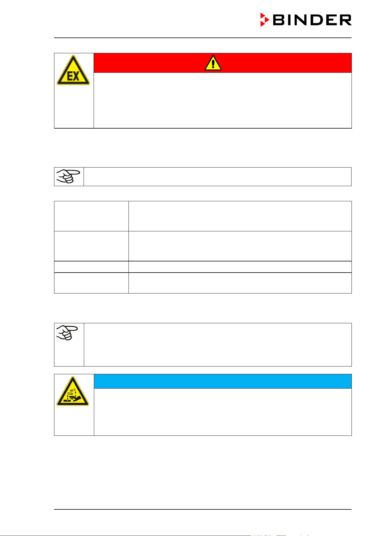
CB / CB-UL, CBF / CBF-UL (E7) 07/2022 Page 150/199
DANGER
Danger of explosion due to cleaning agents on hot surfaces.
Serious injury or death from burns and / or explosion pressure.
Before cleaning, turn off the chamber at the main power switch and disconnect the
power plug.
Before cleaning, let the chamber cool down to ambient temperature.
Completely dry the chamber before turning it on again.
21.1 Cleaning
Disconnect the chamber from the power supply before cleaning. Disconnect the power plug.
The interior of the chamber must be kept clean. Thoroughly remove any residues of the
charging material.
Wipe the surfaces with a moistened towel. In addition, you can use the following cleaning agents:
Exterior surfaces,
instrument panel
Standard commercial cleaning detergents free from acid or halides.
Alcohol-based solutions.
We recommend using the neutral cleaning agent Art. No. 1002-0016.
Inner chamber,
shelves,
fresh water can (option)
Standard commercial cleaning detergents free from acid or halides.
Copper sulfate solutions or alcohol-based solutions.
We recommend using the neutral cleaning agent Art. No. 1002-0016.
Silicone door gasket Alcohol-based solutions or the neutral cleaning agent Art. No. 1002-0016.
Zinc coated hinge parts
rear chamber wall
Standard commercial cleaning detergents free from acid or halides.
Do NOT use a neutral cleaning agent on zinc coated surfaces.
Do not use cleaning agents that may cause a hazard due to reaction with components of the device or the
charging material. If there is doubt regarding the suitability of cleaning products, please contact BINDER
service.
We recommend using the neutral cleaning agent Art. No. 1002-0016 for thorough cleaning.
Any corrosive damage that may arise following use of other cleaning agents is excluded from
liability by BINDER GmbH.
Any corrosive damage caused by a lack of cleaning, is excluded from liability by BINDER
GmbH.
NOTICE
Danger of corrosion by using unsuitable cleaners.
Damage to the chamber.
∅ Do NOT use acidic or chlorine cleaning detergents.
∅ Do NOT use a neutral cleaning agent on other kind of surfaces e.g., the zinc coated
hinge parts or the rear chamber wall.
To maintain the proper function of the CO
2
sensor, never spray the sensor with any cleaning detergents or
disinfectants.
CB / CB-UL, CBF / CBF-UL (E7) 07/2022 Page 151/199
NOTICE
Damage to the CO
2
sensor due to unsuitable cleaning procedures.
∅ NEVER spray any cleaning detergents directly on the CO
2
sensor.
Wipe the sensor with a lint-free cloth soaked with cleaning agent.
Use only the detergents or disinfectants recommended by BINDER. Other products are not approved, since
they could in particular damage the CO
2
sensor.
For surface protection, perform cleaning as quickly as possible.
After cleaning completely remove any cleaning agents from the surfaces by using a
moistened towel. Let the chamber dry.
Soapsuds may contain chlorides and must therefore NOT be used for cleaning.
With every decontamination method, always use adequate personal safety controls.
Following cleaning, leave the chamber door open or remove the access port plugs.
The neutral cleaning agent may cause health problems in contact with skin and if
ingested. Follow the operating instructions and safety hints labeled on the bottle of the
neutral cleaning agent.
Recommended precautions: To protect the eyes use sealed protective goggles. Wear gloves. Suitable
protective gloves in full contact with media: butyl or nitrile rubber, penetration time >480 minutes.
CAUTION
Danger of chemical burns through contact with skin or ingestion of the
neutral cleaning agent.
Skin and eye damage. Environmental damage.
∅ Do not ingest the neutral cleaning agent. Keep it away from food and
beverages.
∅ Do NOT empty the neutral cleaning agent into drains.
Wear protective gloves and goggles.
Avoid skin contact with the neutral cleaning agent.
Following use of the neutral cleaning agent and prior to hot-air sterilization, remove any agent
residues by using a moistened towel in order to avoid formation of permanent residues.
21.2 Decontamination / chemical disinfection of the chamber
The operator must ensure that proper decontamination is performed in case a contamination of the chamber
by hazardous substances has occurred.
Disconnect the chamber from the power supply prior to chemical decontamination. Disconnect the power
plug.
Do not use decontamination agents that may cause a hazard due to reaction with components of the device
or the charging material. If there is doubt regarding the suitability of cleaning products, please contact
BINDER service.
CB / CB-UL, CBF / CBF-UL (E7) 07/2022 Page 152/199
You can use the following disinfectants:
Inner chamber
Standard commercial surface disinfectants free from acid or halides.
Alcohol based solutions.
We recommend using the disinfectant spray Art. No. 1002-0022.
Fresh water can
(option)
Rinse with 70° Ethanol
For chemical disinfection, we recommend using the disinfectant spray Art. No. 1002-0022.
Any corrosive damage that may arise following use of other disinfectants is excluded from
liability by BINDER GmbH.
With every decontamination method, always use adequate personal safety controls.
In case of contamination of the interior by biologically or chemically hazardous material, there are two
possible procedures depending on the type of contamination and charging material.
• Spray the inner chamber with an appropriate disinfectant.
Before start-up, the chamber must be absolutely dry and ventilated, as explosive gases may form during
the decontamination process.
• If necessary, have strongly contaminated inner chamber parts removed by an engineer for cleaning, or
have them exchanged. Sterilize the inner chamber parts in a sterilizer or autoclave.
In case of eye contact, the disinfectant spray may cause eye damage due to chemical
burns. Follow the operating instructions and safety hints labeled on the bottle of the
disinfectant spray.
Recommended precautions: To protect the eyes use sealed protective goggles.
CAUTION
Danger of chemical burns through eye contact with the disinfectant
spray.
Eye damage. Environmental damage.
∅ Do NOT empty the disinfectant spray into drains.
Wear protective goggles.
Following frequent use of the disinfectant spray and prior to hot-air sterilization, remove any
agent remainder by using the neutral cleaning agent and then a moistened towel to avoid
formation of permanent residues.
After using the disinfectant spray, allow the chamber to dry thoroughly, and aerate it
sufficiently.
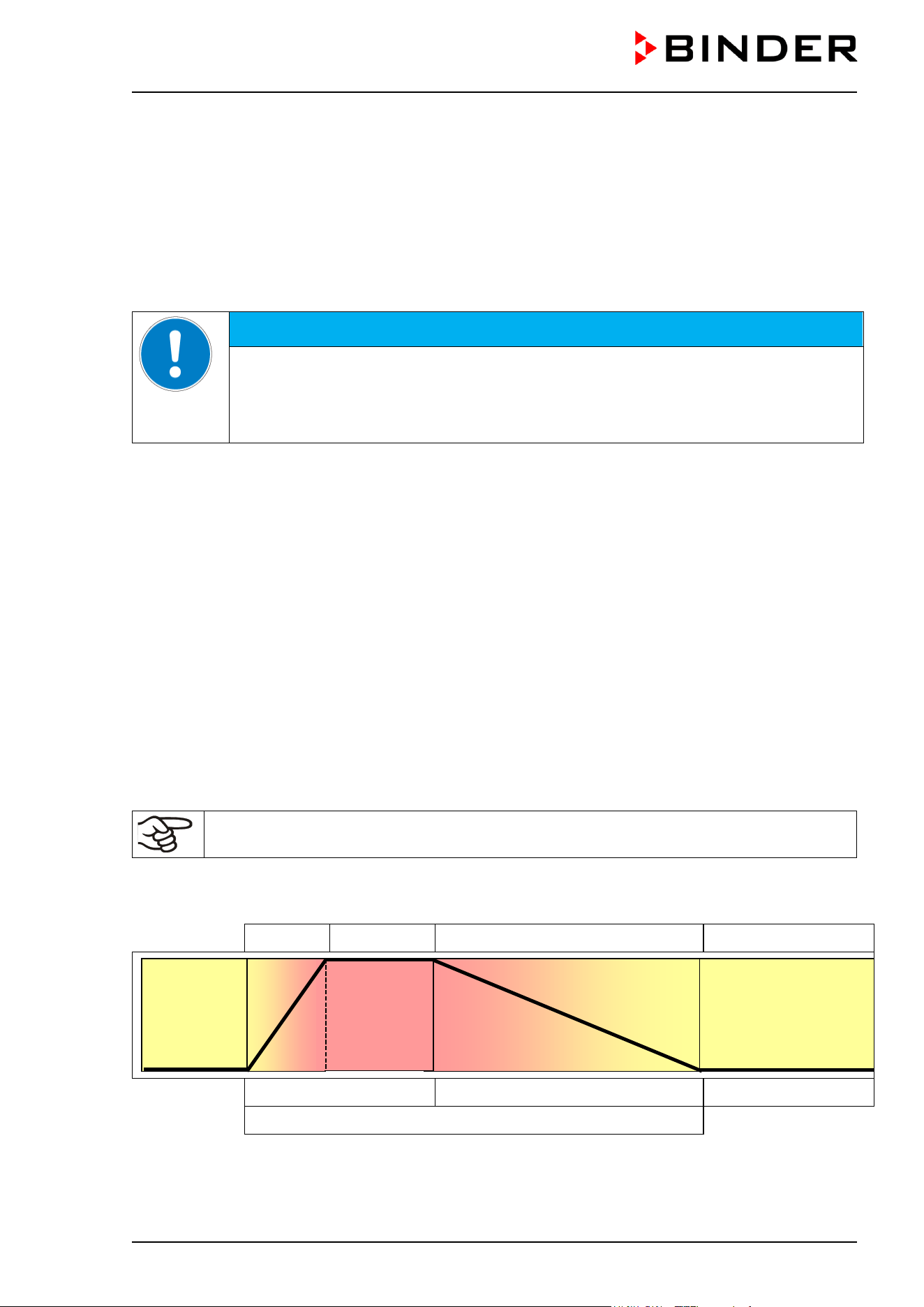
CB / CB-UL, CBF / CBF-UL (E7) 07/2022 Page 153/199
21.2.1 Disinfection of the CO
2
sensor
To ensure proper disinfection and function of the CO
2
sensor, BINDER recommends wiping the sensor
head with pure alcohol or a non-corrosive, acid and chlorine-free alcohol based surface disinfectant. We
recommend using the disinfectant spray Art. No. 1002-0022.
Important: To maintain the proper function of the CO
2
sensor, never spray the sensor with any cleaning
detergents or disinfectants. Generally perform any disinfection only when the chamber is turned off. The
sensor may be only superficially disinfected with a damp cloth. The hot air sterilization routine is intended
for a thorough sterilization of the entire chamber.
NOTICE
Danger of damage to the CO
2
sensor due to unsuitable disinfection procedures.
Damage to the CO
2
sensor.
∅ NEVER spray the disinfectant directly on the CO
2
sensor.
Wipe the sensor with a lint-free cloth soaked with the disinfectant.
Use only the detergents or disinfectants recommended by BINDER. Other products are not approved, since
they could in particular damage the CO
2
sensor.
21.2.2 CBF / CBF-UL: Disinfection of components of the fresh water supply system
Freshwater is supplied by manually filling a freshwater bag (tubular bag set, standard, can be reordered)
or a freshwater can (optional water container set). It is also possible to connect prefilled water bottles
(optional humidification water set).
The freshwater bag can be refilled several times, but should be replaced from time to time for hygienic
reasons.
The silicone tubes and tube connectors can be autoclaved. They can also be replaced for hygienic reasons.
For the fresh water can we recommend thorough cleaning using a recommended cleaning agent (chap.
21.1) followed by rinsing with 70 % ethanol.
21.3 Hot-air sterilization
The very first sterilization after operation may cause an odor. This is not a quality defect. We
recommend ventilating well the room during sterilization.
21.3.1 Overview
Heating up
Holding Cooling down Equilibrating
4 hours 6 hours
unlimited
Sterilization cycle of 10 hours
Figure 50: Setpoint profile during the sterilization cycle
37 °C
180 °C
CB / CB-UL, CBF / CBF-UL (E7) 07/2022 Page 154/199
The chamber can perform an automatically controlled hot-air sterilization cycle. This procedure of 10 hours
consists of the following steps:
• Heating up phase: The chamber heats up the inner chamber as fast as possible to the sterilization
setpoint temperature
• Holding phase: Constant sterilization setpoint temperature
The sterilization setpoint temperature is pre-set in factory to 180 °C / 356 °F. The duration of the heating
up and holding phase is in total 4 hours. This ensures that the effective sterilization temperature is
maintained on all internal surfaces for at least 2 hours. The effectiveness of the sterilization has also
been confirmed by an independent research institute.
• Cooling down phase: Programmed duration of 6 hours until 37 °C / 98.6°F is reached
• Then follows an equilibration phase: After the 10-hour sterilization cycle the controller changes to fixed
value operation mode and equilibrates to the set-point which has been entered there (e.g., 37 °C /
98.6 °F).
Note: in the case when two chambers are directly stacked on top of each other without using the original
BINDER stacking stand or the BINDER stacking adapter, the exact maintenance of the incubation set
parameters in one of the chambers while carrying out sterilization in the other one cannot be assured.
Therefore, without using the stacking stand or the stacking adapter, safe incubation is not possible during
sterilization of the other chamber. We recommend using a stacking stand (chap. 18.8.2).
CO
2
/ O
2
control is deactivated during the sterilization cycle. To activate gas control, the following conditions
are required:
• Completing or prematurely terminating the sterilization cycle and confirming the corresponding
information message
• Inner chamber temperature below 80 °C
If the temperature exceeds < 80 °C, gas control will remain deactivated even after completing
or prematurely terminating the sterilization cycle.
Only after the temperature has decreased below 80 °C, gas control will turn on again.
21.3.2 Preparation for a hot-air sterilization
Before carrying out the first hot-air sterilization, remove any protective lamination sheet from
the inner metal surfaces.
When starting a hot-air sterilization, all gas controls automatically deactivate.
The safety controller settings are inactive during sterilization. They become functional again
following completing or prematurely terminating of the sterilization cycle and/or restart of the
chamber at the main power switch.
The O
2
sensor must be plugged in during a hot-air sterilization.
• Empty the Permadry™ water pan.
WARNING
Danger of implosion caused by a filled water pan during sterilization.
Destruction of the chamber.
Empty the Permadry™ water pan before starting the hot-air sterilization.
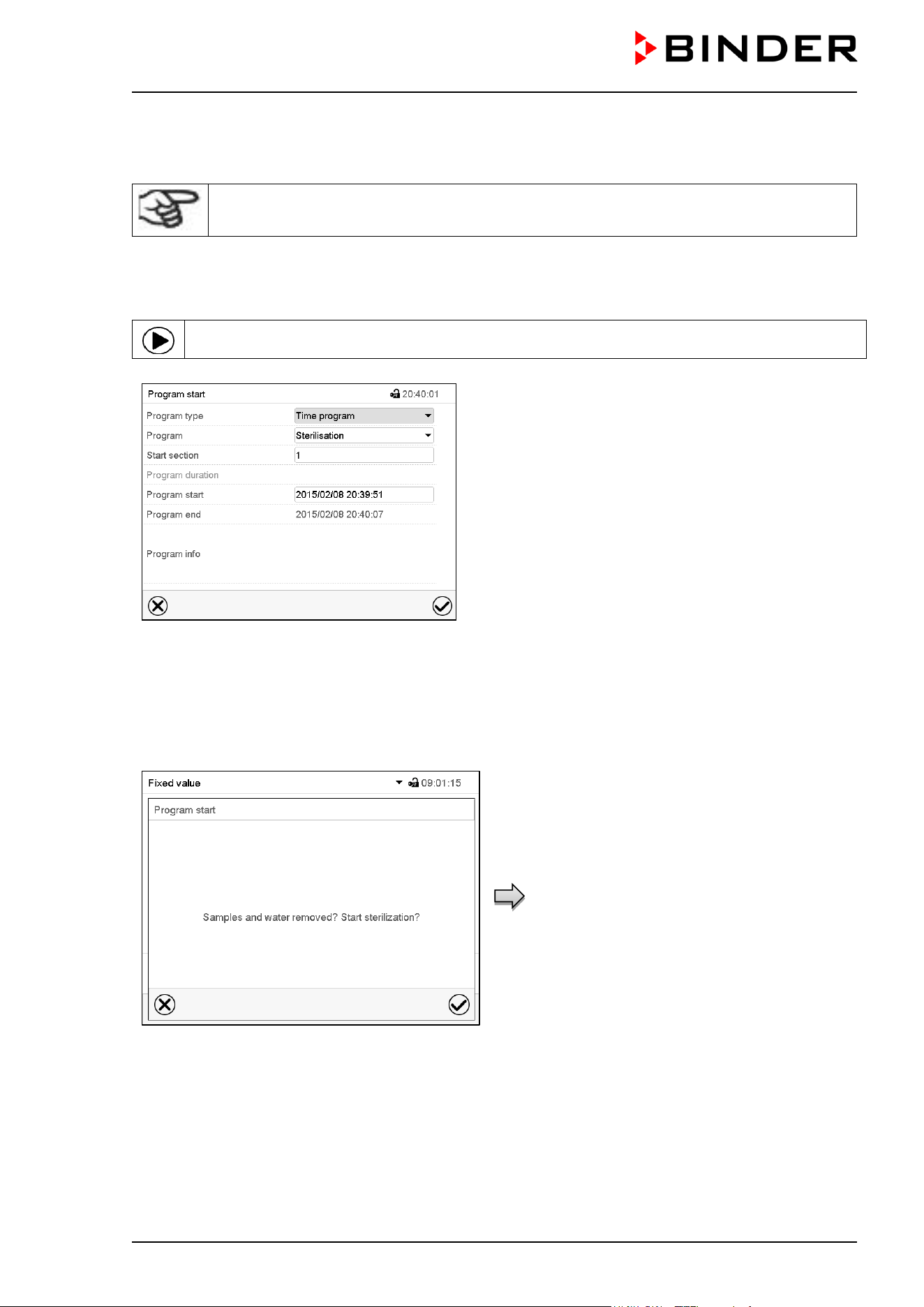
CB / CB-UL, CBF / CBF-UL (E7) 07/2022 Page 155/199
• Water pans and shelves must be inside the chamber.
• Close the inner glass door and the outer chamber door.
Before starting a hot-air sterilization, the entire interior must be clean and dry. No residue of
e.g., water, medium or plastic must remain inside the chamber.
21.3.3 Starting the sterilization cycle and running the hot-air sterilization
In Normal display press the Program start icon to access the “Program start” menu.
“Program start” menu
• In the field “Program type” select the setting “Time program”.
• In the field “Program” select the program “Sterilization”.
• Select the field “Program start” and enter the desired program start time in the “Program start” entry
menu. Press the Confirm icon.
A confirmation prompt is displayed.
Make sure that the water pan was emptied and
all samples were removed from the chamber and
press the Confirm icon to confirm the message.
The controller returns to the initial view and the
program delay time until program start begins.
When the program delay time is over, the hot-air
sterilization cycle begins.
Confirmation prompt.
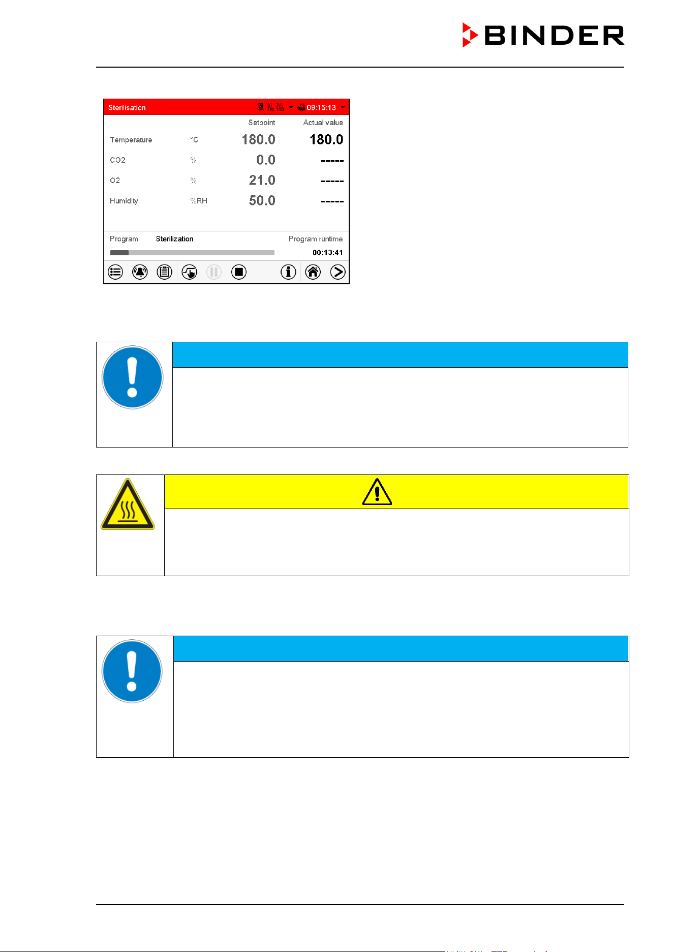
CB / CB-UL, CBF / CBF-UL (E7) 07/2022 Page 156/199
Normal display with alarm message “Sterilization”.
The sterilization is running.
The zero-voltage relay alarm output and the buzzer
are not activated.
Opening the outer door leads to prematurely terminating the running sterilization cycle. If this happens
during the heating up or holding phase (during 4 hours after starting the sterilization cycle), sterilization will
be ineffective (chap. 21.3.4.1).
NOTICE
Danger of interrupting the temperature reaction time by opening the outer door
during the heating up or holding phase.
Ineffective sterilization.
∅ Do NOT open the chamber doors during the heating up or holding phase of the
sterilization cycle
Glass door and inner chamber become hot during sterilization.
CAUTION
Danger of burning by touching hot chamber parts during a sterilization.
Burns.
∅ Do NOT touch the inner surfaces, inner doors, inner door handles, and door gaskets
during a sterilization.
Note: Since the stored sterilization program cannot be changed, it is not accessible via the program path
Main menu > Programs > Time program.
The sterilization program must not be interrupted using the Program pause icon.
NOTICE
Danger of interrupting the temperature reaction time by pausing the sterilization
program during the heating up or holding phase.
Ineffective sterilization.
∅ DO NOT interrupt a running sterilization program during the heating up or holding
phase of the sterilization cycle.
If necessary, repeat the sterilization.
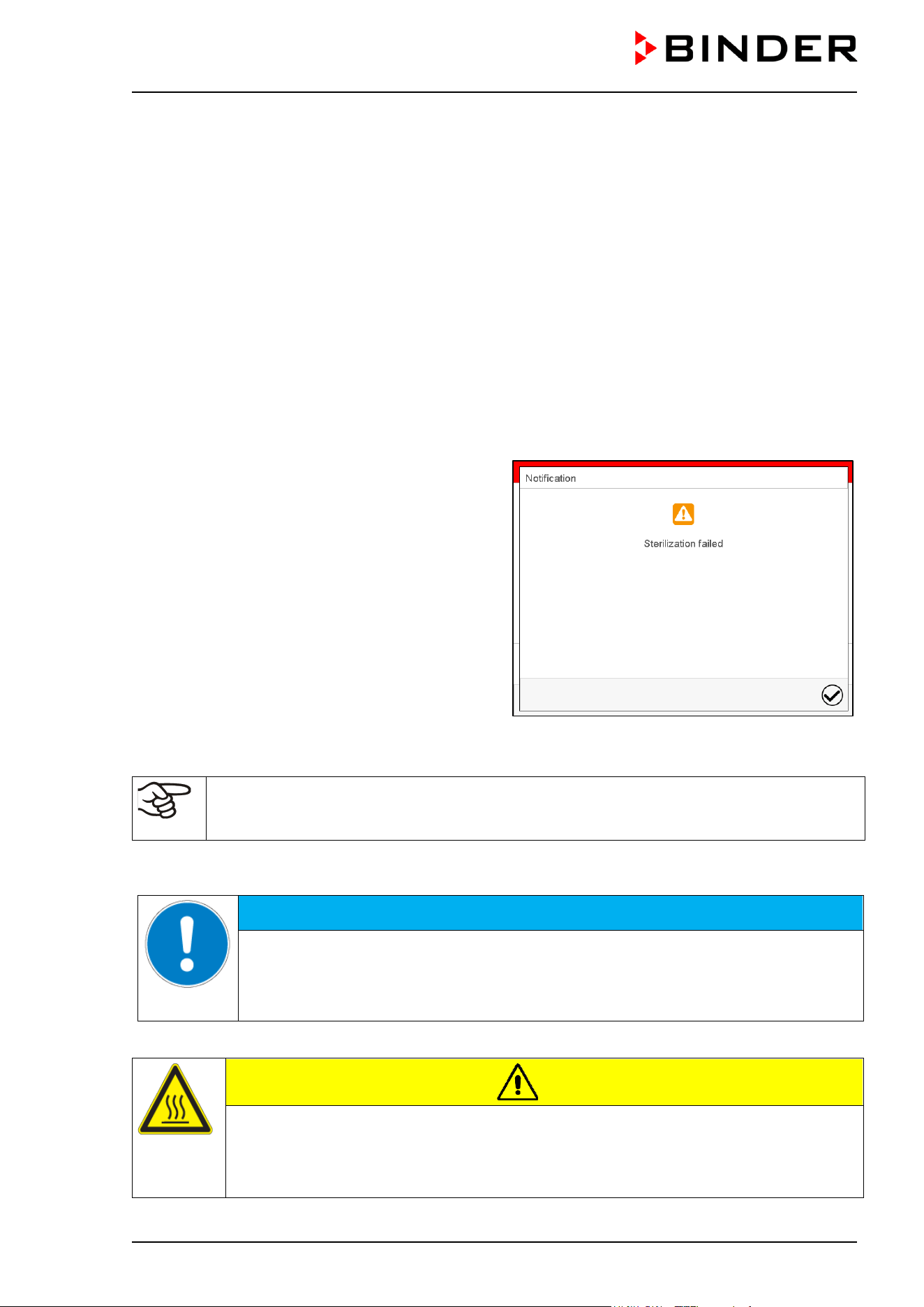
CB / CB-UL, CBF / CBF-UL (E7) 07/2022 Page 157/199
21.3.4 Prematurely terminating the sterilization cycle
Three events lead to terminating the sterilization cycle prematurely:
• Cancelling the program via the controller menu
To prematurely terminate the sterilization cycle via the controller menu, press the Program cancelling
icon and confirm the confirmation prompt with the Confirm icon (chap. 9.2.2).
• Opening the outer door
• Turning off the chamber at the main power switch, or a power failure
Prematurely terminating the sterilization cycle means terminating it before the entire 10-hour duration is
completed. Whether effective sterilization has occurred depends on the time that has elapsed before.
21.3.4.1 Prematurely terminating the sterilization cycle after less than 4 hours: Ineffective
sterilization
After prematurely terminating the sterilization
cycle after less than 4 hours, t
he information
“Sterilization failed” is shown on the controller
display.
The interior may still be hot. Do not touch the
glass door and inner surfaces!
Confirm the message with the Confirm icon.
After confirming the message the controller changes to Fixed value operation mode. The setpoints of Fixed
value operation mode are then equilibrated.
CO
2
/ O
2
control is deactivated and will only be activated after confirming the information
message “Sterilization failed” and when the temperature has cooled down to a value below <
80 °C.
When prematurely terminating the sterilization cycle, it may be that the cells/pathogens inside the chamber
have not all been killed. If necessary, you should repeat the sterilization.
NOTICE
Danger of interrupting the temperature reaction time by prematurely terminating
the sterilization.
Ineffective sterilization.
If necessary, repeat the sterilization.
The glass door and inner chamber become hot during sterilization.
CAUTION
Danger of burning by touching hot chamber parts during or after a sterilization.
Burns.
∅ Do NOT touch the glass door and inner surfaces for approx. 7 hours after prematurely
terminating the sterilization cycle.
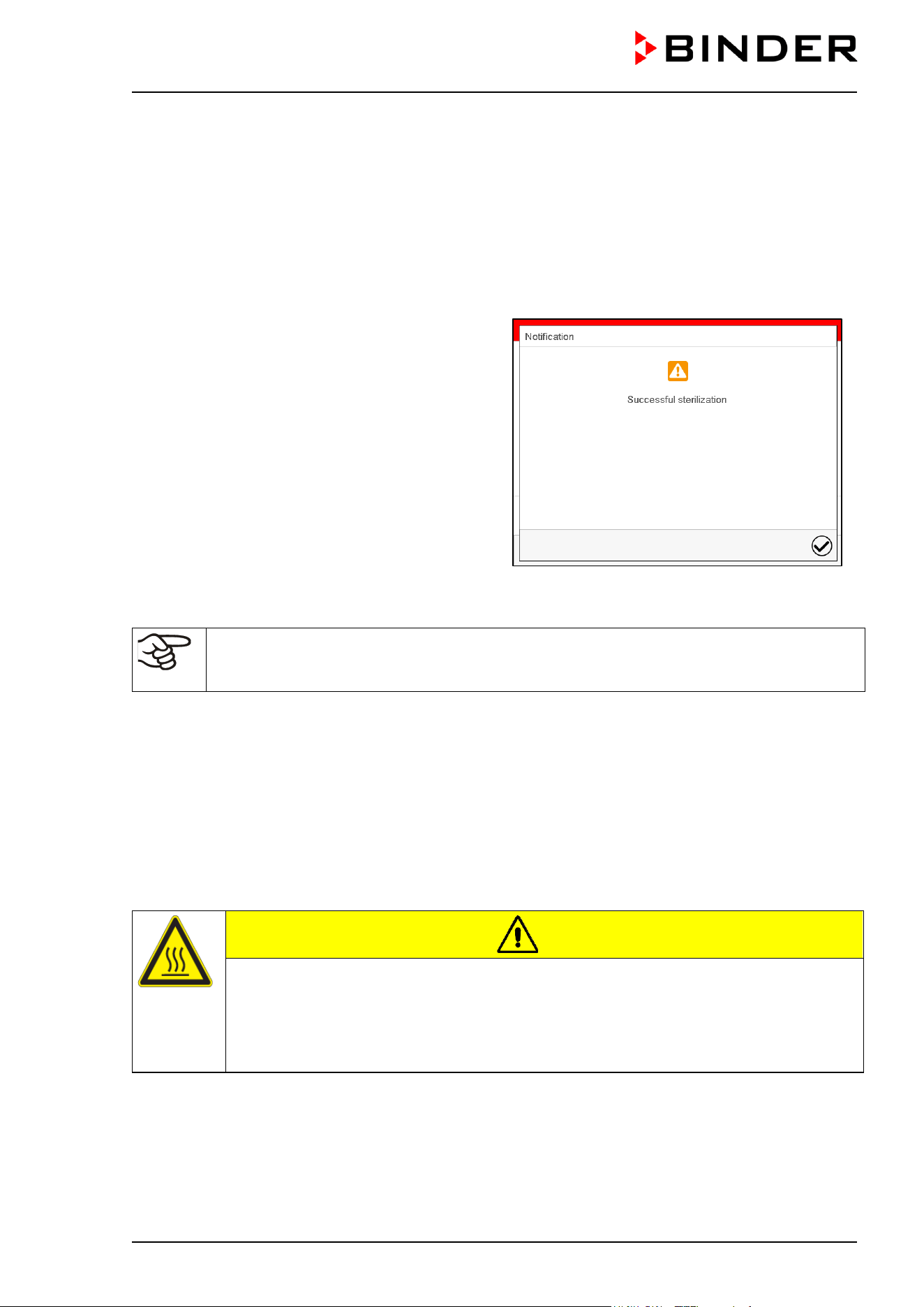
CB / CB-UL, CBF / CBF-UL (E7) 07/2022 Page 158/199
21.3.4.2 Prematurely terminating the sterilization cycle after more than 4 hours, i.e.,
during the cooling-down phase: successful sterilization
The duration of the entire sterilization is 10 hours. If you want to shorten the sterilization procedure in order
to save time, you can prematurely terminate it during the cooling-down phase, i.e. no sooner than after 4
hours. At this point, the inner temperature is still approx. 140 °C / 284 °F.
The effective sterilization phase (heating up and holding phase) is automatically finished after 4 hours The
chamber is in the cooling-down phase, meaning that the necessary duration for the proper sterilization has
occurred.
The information “Successful sterilization” on the
controller display indicates a successful hot-air
sterilization.
The interior may still be hot. Do not touch the
glass door and inner surfaces!
Confirm the message with the Confirm icon.
After confirming the message the controller changes to Fixed value operation mode. The setpoints of Fixed
value operation mode are then equilibrated.
CO
2
/ O
2
control is deactivated and will only be activated after confirming the information
message “Successful sterilization” and when the temperature has cooled down to a value
below < 80 °C.
If you prefer accelerating cooling-down, proceed as follows:
• If required, open the outer door.
• Cooling-down time:
• Front door open: at least 1 hour
• Front door closed: at least 4 hours
• If required, open the glass door.
Glass door and inner chamber become hot during sterilization. The glass door handle reaches a
temperature of approx. 150 °C / 302 °F.
CAUTION
Danger of burning through touching the glass door and inner chamber during or
after a sterilization.
Burns.
∅ Do NOT touch the glass door and inner surfaces.
Use gloves or a tool (e.g. pincers) to open the glass door.
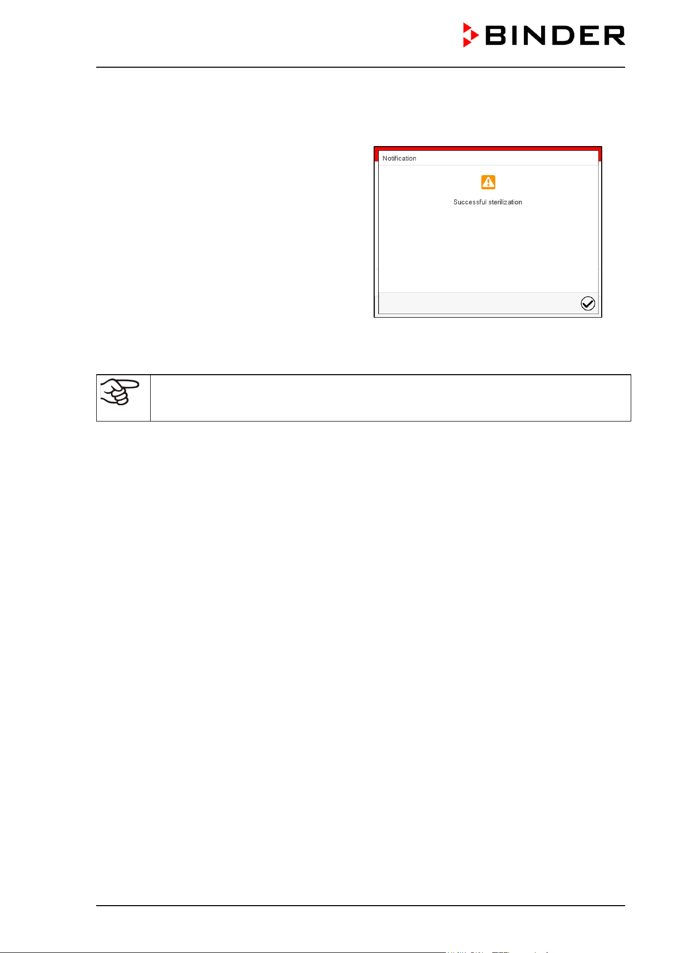
CB / CB-UL, CBF / CBF-UL (E7) 07/2022 Page 159/199
21.3.5 Completing the entire sterilization cycle
The effective sterilization phase (heating up and holding phase) is automatically finished after 4 hours.
Now the information “Successful sterilization” on
the controller display indicates a successful hot-
air sterilization.
Confirm the message with the Confirm icon.
It is followed by a defined 6-hours cooling down phase until 37 °C / 98.6 °F is reached. After this sterilization
cycle of 10 hours in total, the controller changes to fixed value operation mode and equilibrates to the set-
point which has been entered there (e.g., 37 °C / 98.6 °F).
CO
2
/ O
2
control is deactivated and will only be activated after confirming the information
message “Successful sterilization” and when the temperature has cooled down to a value
below < 80 °C.
22. Maintenance and service, troubleshooting, repair, testing
22.1 General information, personnel qualification
• Maintenance
See chap. 22.5.
• Simple troubleshooting
Chap. 22.6 describes troubleshooting by operating personnel. It does not require technical intervention
into the chamber, nor disassembly of chamber parts.
For personnel requirements please refer to chap. 1.1.
• Detailed troubleshooting
If errors cannot be identified with simple troubleshooting, further troubleshooting must be performed by
BINDER Service or by BINDER qualified service partners or technicians, in accordance with the
description in the Service Manual.
For personnel requirements please refer to the Service Manual.
• Repair
Repair of the chamber can be performed by BINDER Service or by BINDER qualified service partners
or technicians, in accordance with the description in the Service Manual.
After maintenance, the chamber must be tested prior to resuming operation.
• Electrical testing
To prevent the risk of electrical shock from the electrical equipment of the chamber, an annual repeat
inspection as well as a test prior to initial startup and prior to resuming operation after maintenance or
repair, are required. This test must meet the requirements of the competent public authorities. We
recommend testing under DIN VDE 0701-0702:2008 in accordance with the details in the Service
Manual.
For personnel requirements please refer to the Service Manual.
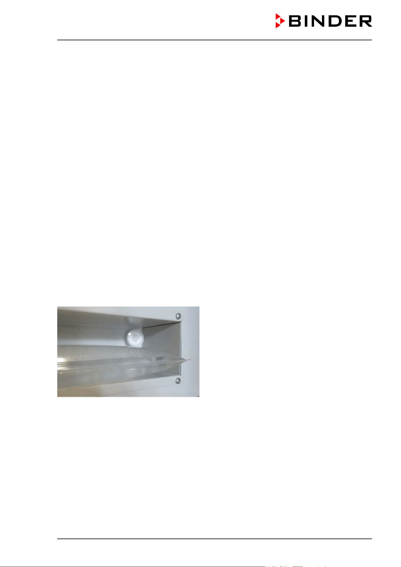
CB / CB-UL, CBF / CBF-UL (E7) 07/2022 Page 160/199
22.2 CBF / CBF-UL: Replacing components of the humidifying / dehumidifying
system
22.2.1 Replacing the silicone tube of the fresh water supply system
The silicone tube (DN 3mm) (art. no. 6008-0267) is included with the following humidifying sets:
• Tubular bag set with 3 tubular bags (Art. No. 8009-1083, included): 6 m (chap. 4.5.2)
• Tubular bag set with 12 tubular bags (Art. No. 8009-1058, option): 6 m (chap. 4.5.2)
• Humidification water set (Art. No. 8009-1104, option): 2 m (chap. 4.5.3)
• Water container set (Art. No. 8009-1128, option): 10 m (chap. 4.5.4)
It is also available by the meter from BINDER.
To operate the freshwater supply via tubular bags (standard), a total length of 32 cm is required.
To replace the DN 3mm silicone tube, proceed as described in chap. 4.5.
22.2.2 Replacing the pump head of the fresh water supply system
A pump head for the tube pump for freshwater supply is available under art.no. 5013-0204. To replace the
pump head, proceed as described in chap. 4.5.
22.2.3 Replacing the gas fine filter (sterile filter) for ambient air
The air tube for inlet of the ambient air is located in the upper right corner in the recess for the freshwater
bag. We recommend replacing the gas fine filter (sterile filter) on this tube about once a month. To do this,
hold the sterile filter and pull out a bit the air tube connected to it. Unscrew the filter and screw on a new
filter. Then push the tube back in.
Figure 51: Location of the gas fine filter (sterile filter) in the recess for the freshwater bag
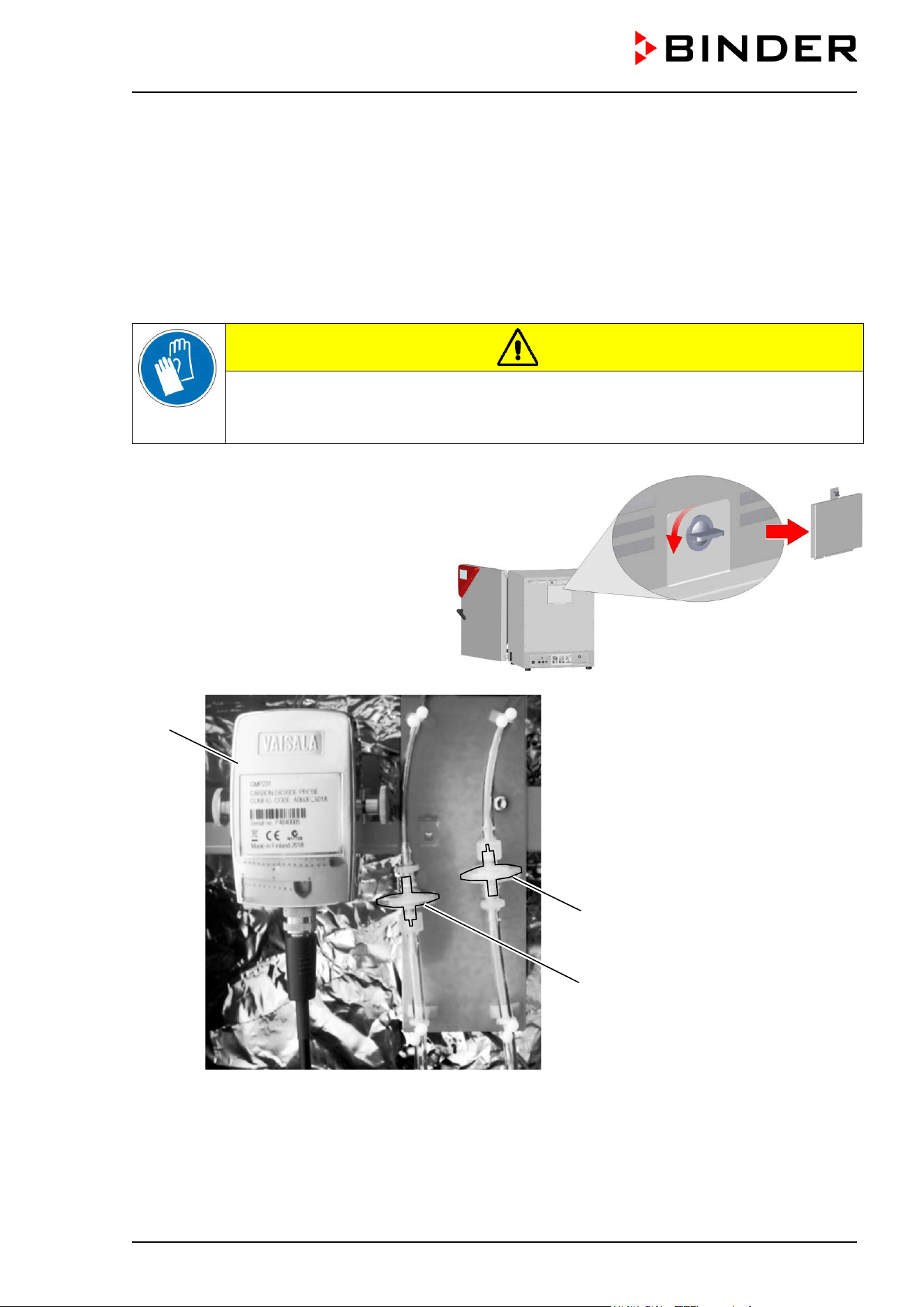
CB / CB-UL, CBF / CBF-UL (E7) 07/2022 Page 161/199
22.3 Replacing the CO
2
und O
2
/N
2
gas inlet fine filters (sterile filters)
When the chamber is in operation, the incoming gas passes through a fine gas filter (aseptic filter, filtration
efficiency 99.99 %, particle size 0.45 µm).This fine filter prevents dirt accumulating in the gas inlet valves
and the tubes leading into the inner chamber, which could be in the gas cylinder or in the supply tubes.
When using gas with a technical grade of 99.5 %, we recommend changing the fine gas filter once a year.
Please consult BINDER Service. When using gases with less pureness, the changing intervals should be
shorter.
• Pull the power plug.
CAUTION
Risk of injuries by sharp edges on the rear panel.
Cuts.
Wear protective gloves when removing or installing the cover on the chamber rear
Remove the cover on the chamber rear
(14) CO
2
sensor
(15) Gas fine filter (sterile
filter) for CO
2
(16) Gas fine filter (sterile
filter) for N
2
(chamber with O
2
control)
Figure 52: Position of the CO
2
sensor and the gas fine filters behind the cover
• Unscrew the desired gas fine filter on both sides from the gas tubes and then screw on a new filter.
• Reinstall the cover on the chamber rear.
(14)
(15)
(16)
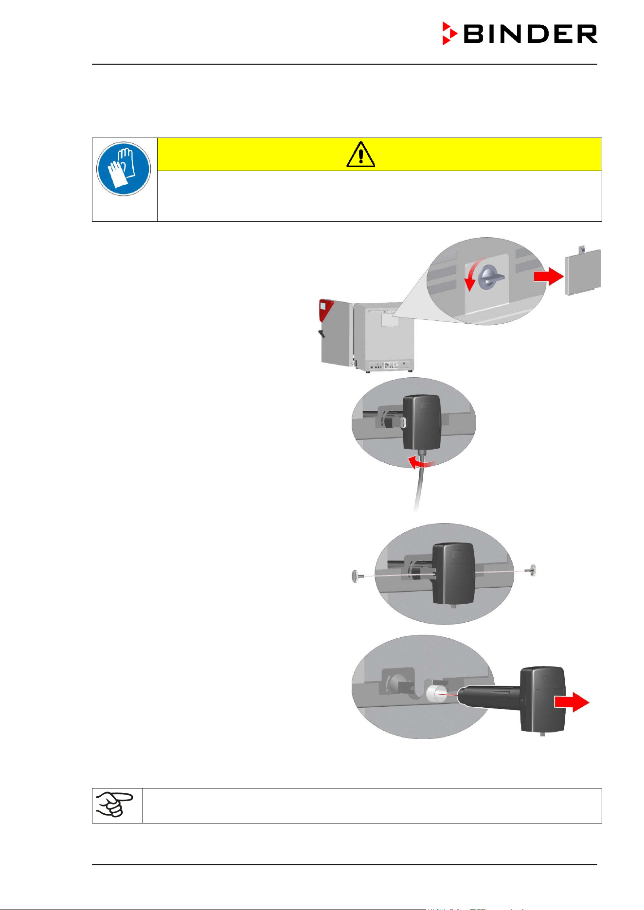
CB / CB-UL, CBF / CBF-UL (E7) 07/2022 Page 162/199
22.4 Replacing the CO
2
sensor
• Pull the power plug.
CAUTION
Risk of injuries by sharp edges on the rear panel.
Cuts.
Wear protective gloves when removing or installing the cover on the chamber rear
• Remove the cover on the chamber rear
The position of the CO
2
sensor behind
the cover is shown in Figure 52.
• Unscrew the cable from the sensor.
Make sure that the sensor cable does not fall
into the inner chamber.
• Remove the fixing screws on both sides of the
sensor.
• Pull the sensor backwards out of the holder. The
filter (white) attached to the sensor is pulled out
together with the sensor.
• Then mount the new sensor proceeding in reverse order
• Reinstall the cover on the chamber rear.
The sensor may only be used with the attached filter.
After replacing the CO
2
sensor repeat the CO
2
calibration.
CB / CB-UL, CBF / CBF-UL (E7) 07/2022 Page 163/199
22.5 Maintenance intervals, service
DANGER
Electrical hazard during live maintenance work.
Deadly electric shock.
∅ The chamber must NOT become wet during operation or maintenance works.
∅ Do NOT remove the rear panel of the chamber.
Before conducting maintenance work, turn off the chamber at the main power switch
and disconnect the power plug.
Make sure that any maintenance work will be conducted by licensed electricians or
experts authorized by BINDER.
Ensure regular maintenance work is performed at least once a year and that the legal requirements are
met regarding the qualifications of service personnel, scope of testing and documentation.
The warranty becomes void if maintenance work is conducted by non-authorized personnel.
CBF / CBF-UL: Have conducted regular maintenance work on the steam humidifier at least once a year.
The operating behavior and the maintenance intervals of the humidifier essentially depend on the available
water quality and the amount of steam produced in the meantime.
Replace the door gasket only when cold. Otherwise, the door gasket may become damaged.
We recommend taking out a maintenance agreement. Please consult BINDER Service.
BINDER telephone hotline: +49 (0) 7462 2005 555
BINDER fax hotline: +49 (0) 7462 2005 93555
BINDER e-mail hotline: customerservice@binder-world.com
BINDER service hotline USA: +1 866 885 9794 or +1 631 224 4340 x3 (toll-free in the USA)
BINDER service hotline Asia Pacific: +852 390 705 04 or +852 390 705 03
BINDER service hotline Russia and CIS +7 495 988 15 16
BINDER Internet website http://www.binder-world.com
BINDER address BINDER GmbH, post office box 102,
78502 Tuttlingen, Germany
International customers, please contact your local BINDER distributor.
The gas sensors are especially adjusted for the individual incubator. When exchanging a
sensor, you must repeat control adjustment for CO
2
and O
2
(chamber with O
2
control).
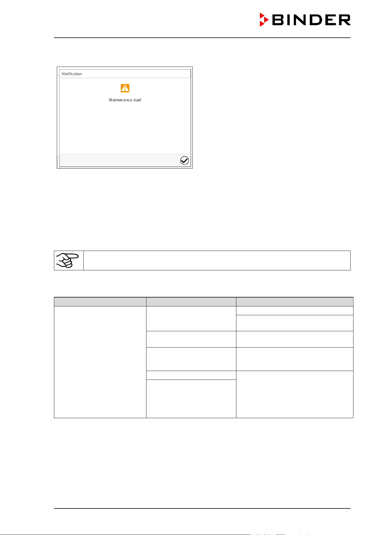
CB / CB-UL, CBF / CBF-UL (E7) 07/2022 Page 164/199
After 8760 operating hours or two years the following message appears:
After confirmation with the Confirm icon, the
message window will pop up again every two
weeks until it is reset by BINDER Service.
22.6 Simple troubleshooting
Defects and shortcomings can compromise the operational safety of the chamber and can lead to risks and
damage to equipment and persons. If there are is a technical fault or shortcoming, take the chamber out of
operation and inform BINDER Service. If you are not sure whether there is a technical fault, proceed
according to the following list. If you cannot clearly identify an error or there is a technical fault, please
contact BINDER Service.
Only qualified service personnel authorized by BINDER must perform repair.
Repaired chambers must comply with the BINDER quality standards.
22.6.1 General
Fault description
Possible cause
Required measures
Chamber without function.
No power supply.
Check connection to power supply.
Check whether the chamber is turned
on at the main power switch.
Wrong voltage.
Check power supply for voltage of 100-
120V or 200-240V.
Chamber fuse has responded.
Check chamber fuse and replace it if
appropriate. If it responds again,
contact BINDER service.
Controller defective.
Contact BINDER service.
Nominal temperature
exceeded by 10 °C due to
chamber failure. Over
temperature protective device
(class 1) responds.
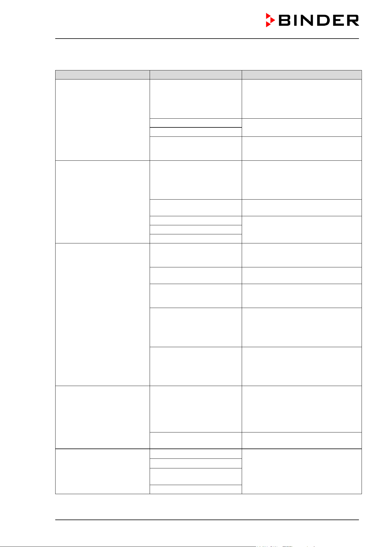
CB / CB-UL, CBF / CBF-UL (E7) 07/2022 Page 165/199
22.6.2 Heating
Fault description
Possible cause
Required measures
Excess temperature. Having
reached the setpoint, the
temperature exceeds the
setpoint by more than the set
tolerance range value (more
than 10 min.)
Alarm message
“Temp. range”
Site of installation too warm.
Difference between the set
temperature and the ambient
temperature too low.
Acknowledge the alarm on the
controller. Observe the difference
between the set temperature and the
ambient temperature, see technical
data chap. 24.4.
Controller defective.
Acknowledge the alarm on the
controller. Contact BINDER service.
Semiconductor relay defective
Temperature controller not
adjusted.
Acknowledge the alarm on the
controller. Calibrate and adjust the
temperature controller.
Excess temperature.
Overtemperature safety
controller class 3.1 responds.
Alarm message
“Safety controller”
Safety controller setpoint
value exceeded.
Acknowledge the alarm on the
controller. Check setting of temperature
setpoint and of the safety controller
class 3.1 setpoint. If appropriate, select
suitable value.
Too much external heat load.
Acknowledge the alarm on the
controller. Reduce heat load.
Controller defective.
Acknowledge the alarm on the
controller. Contact BINDER service.
Semiconductor relay defective
Safety controller defective.
Too low temperature.
Having reached the setpoint,
the temperature falls below the
setpoint by more than the set
tolerance range value (more
than 10 min.) or the
temperature doesn’t reach the
tolerance range within 3 hours
from turning on the chamber or
closing the door.
Alarm message
“Temp. range”
Chamber door not properly
closed.
Acknowledge the alarm on the
controller. Completely close chamber
door.
Door gaskets defective.
Acknowledge the alarm on the
controller. Replace door gasket.
Controller defective.
Acknowledge the alarm on the
controller. Check the function of the
temperature controller.
Door gasket defective. Replace door gasket.
Temperature controller not
adjusted.
Calibrate and adjust the temperature
controller.
Chamber doesn’t heat up.
Alarm message
“Safety controller”“
Inner chamber temperature
has reached the safety
controller setpoint. Safety
controller set too low.
Acknowledge the alarm on the
controller. Check temperature setpoint
setting. If appropriate, select suitable
safety controller setpoint (chap. 12.2).
Safety controller defective.
Acknowledge the alarm on the
controller. Contact BINDER service.
Chamber doesn’t heat up.
Pt 100 sensor defective.
Contact BINDER service.
Heating element defective.
Semiconductor relay
defective.
Controller defective.
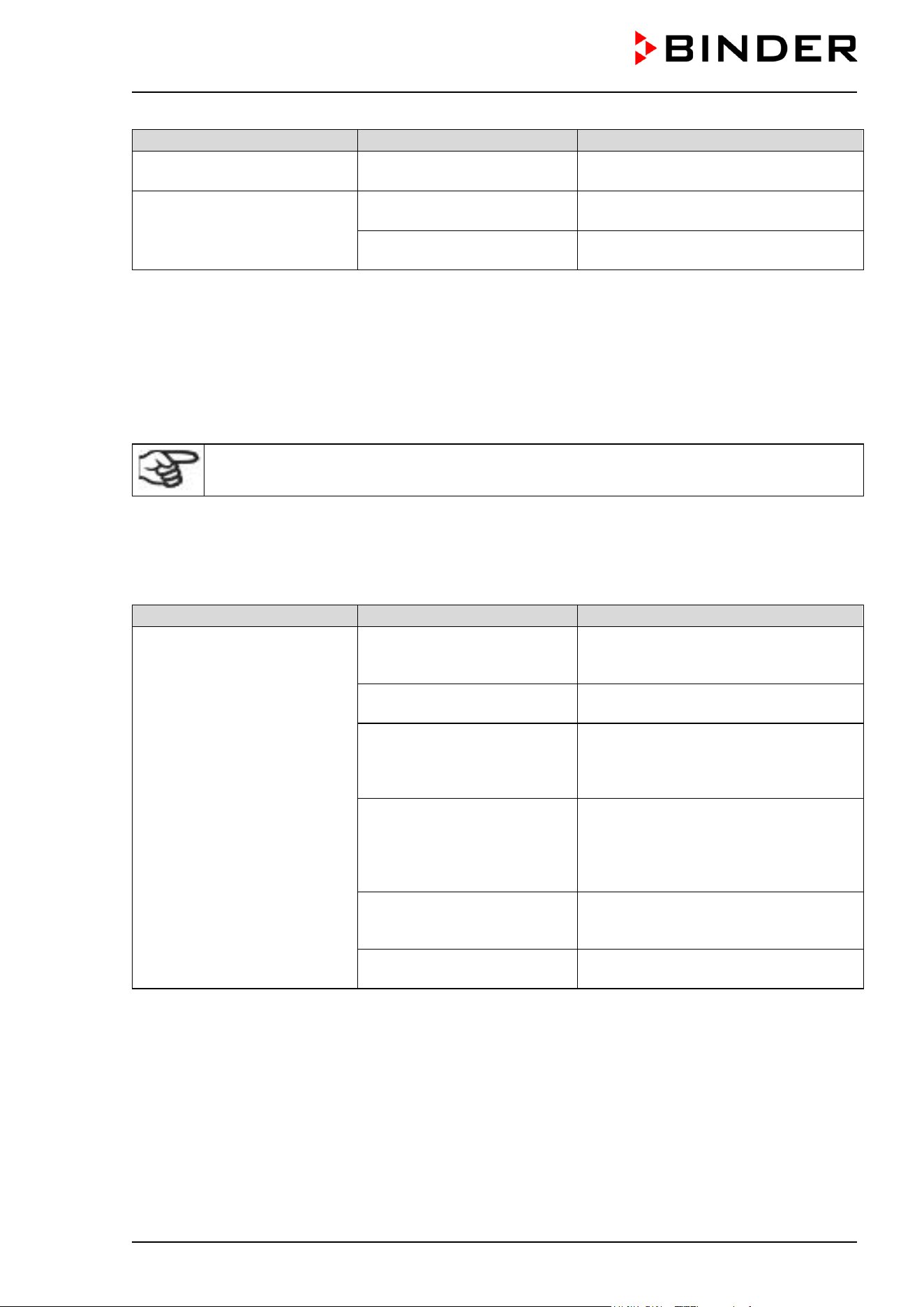
CB / CB-UL, CBF / CBF-UL (E7) 07/2022 Page 166/199
Fault description
Possible cause
Required measures
Very long heating-up times. Chamber fully loaded.
Load the chamber less or consider
longer heating-up times.
The displayed actual
temperature value deviates
largely compared with a
reference method..
Temperature control not
adjusted.
Calibrate and adjust the temperature
control.
Temperature sensor
defective.
Transfer the cultures to another
incubator and contact BINDER Service.
22.6.3 Gas cylinder pressure too low
The alarm messages indicate that the pressure in the supply lines of CO
2
, O
2
(chamber with O
2
control)
and N
2
(chamber with O
2
control) has dropped below 0.3 bar. If no gas cylinder changer is installed, the
gas cylinder must be replaced. Observe the safety instructions and the maximum outlet pressure (chap.
4.4).
Prerequisite for pressure alarm messages for O
2
and N
2
(chamber with O
2
control) is that the
O
2
/ N
2
control with the respective alarms are activated (chap. 6.7, 7.3).
Note: The recovery times of the gas concentrations inside the chamber following door opening, which are
indicated in the technical data (chap. 24.4), refer to a connection pressure of 2.0 bar / 29 psi. Decreasing
supply pressure down to the shift point (alarm point) of 0.3 bar / 4.4 psi results in longer recovery times.
Check the pressure displays of your gas supply. If very short recovery times are required or the door is
opened frequently, replace the gas cylinders promptly when the pressure decreases below 2.0 bar / 29 psi.
Fault description
Possible cause
Required measures
Low CO
2
outlet pressure
(< 0.3 bar)
Alarm message
“CO2 pressure”
CO
2
cylinder is not connected
correctly.
Acknowledge the alarm on the
controller. Correctly connect the gas
cylinder.
Connected gas cylinder is
closed.
Acknowledge the alarm on the
controller. Open the gas cylinder.
Connected gas cylinder is
empty.
Acknowledge the alarm on the
controller. Replace the gas cylinder.
Observe the safety instructions and the
maximum outlet pressure (chap. 4.4).
Gas hose is dirty or
obstructed.
Acknowledge the alarm on the
controller. Turn off the gas supply and
remove the gas connections. Check the
tube system for dirt accumulation or
obstruction, clean or replace it.
Controller malfunction.
Acknowledge the alarm on the
controller. If necessary, contact
BINDER Service.
Pressure sensor system
defective.
Acknowledge the alarm on the
controller. Contact BINDER Service.
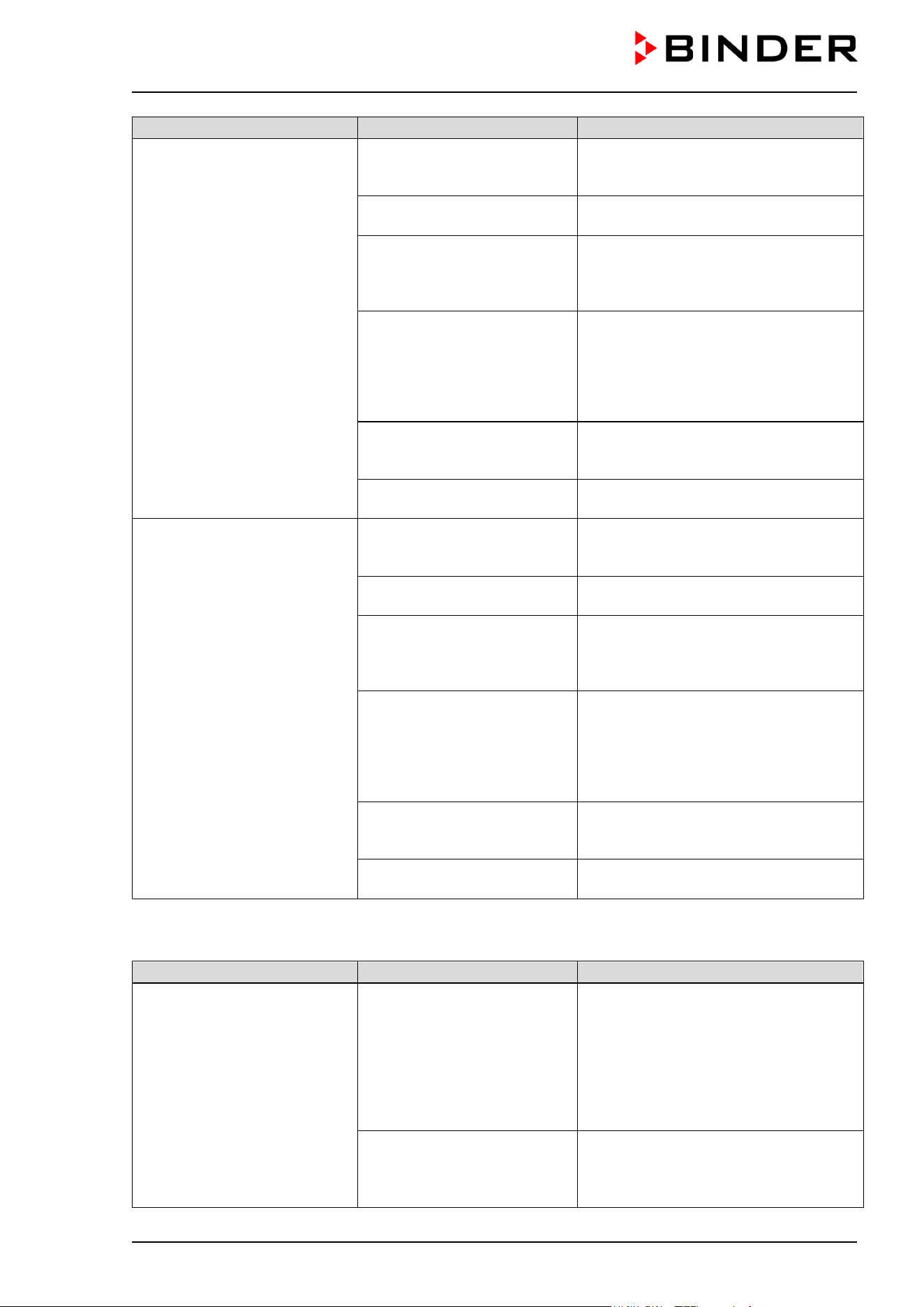
CB / CB-UL, CBF / CBF-UL (E7) 07/2022 Page 167/199
Fault description
Possible cause
Required measures
Chamber with O
2
control:
Low O
2
outlet pressure
(< 0.3 bar).
Alarm message
“O2 pressure”
O
2
cylinder is not connected
correctly.
Acknowledge the alarm on the
controller. Correctly connect the gas
cylinder.
Connected gas cylinder is
closed.
Acknowledge the alarm on the
controller. Open the gas cylinder.
Connected gas cylinder is
empty.
Acknowledge the alarm on the
controller. Replace the gas cylinder.
Observe the safety instructions and the
maximum outlet pressure (chap. 4.4).
Gas hose is dirty or
obstructed.
Acknowledge the alarm on the
controller. Turn off the gas supply and
remove the gas connections. Check the
tube system for dirt accumulation or
obstruction, clean or replace it.
Controller malfunction
Acknowledge the alarm on the
controller. If necessary, contact
BINDER Service.
Pressure sensor system
defective.
Acknowledge the alarm on the
controller. Contact BINDER Service.
Chamber with O
2
control:
Low N
2
outlet pressure
(< 0.3 bar).
Alarm message
“N2 pressure”
N
2
cylinder is not connected
correctly.
Acknowledge the alarm on the
controller. Correctly connect the gas
cylinder.
Connected gas cylinder is
closed.
Acknowledge the alarm on the
controller. Open the gas cylinder.
Connected gas cylinder is
empty.
Acknowledge the alarm on the
controller. Replace the gas cylinder.
Observe the safety instructions and the
maximum outlet pressure (chap. 4.4).
Gas hose is dirty or
obstructed.
Acknowledge the alarm on the
controller. Turn off the gas supply and
remove the gas connections. Check the
tube system for dirt accumulation or
obstruction, clean or replace it.
Controller malfunction
Acknowledge the alarm on the
controller. If necessary, contact
BINDER Service.
Pressure sensor system
defective.
Acknowledge the alarm on the
controller. Contact BINDER Service.
22.6.4 Gas control
Fault description
Possible cause
Required measures
Excess CO
2
concentration.
Having reached the setpoint,
CO
2
exceeds the setpoint by
more than the set tolerance
range value (more than 10
min.)
Alarm message
“CO2 range”
Temporary disturbance of the
CO
2
control.
Acknowledge the alarm on the
controller. Turn off the chamber. Open
the chamber doors for approx. 5
minutes. Observe the general
information for safe handling of CO
2
(chap. 1.9
). Turn on the chamber again.
Upon renewed alarm, contact BINDER
service.
CO
2
sensor defective.
Acknowledge the alarm on the
controller. Contact BINDER Service.
To replace the sensor proceed as
described in chap. 22.4.
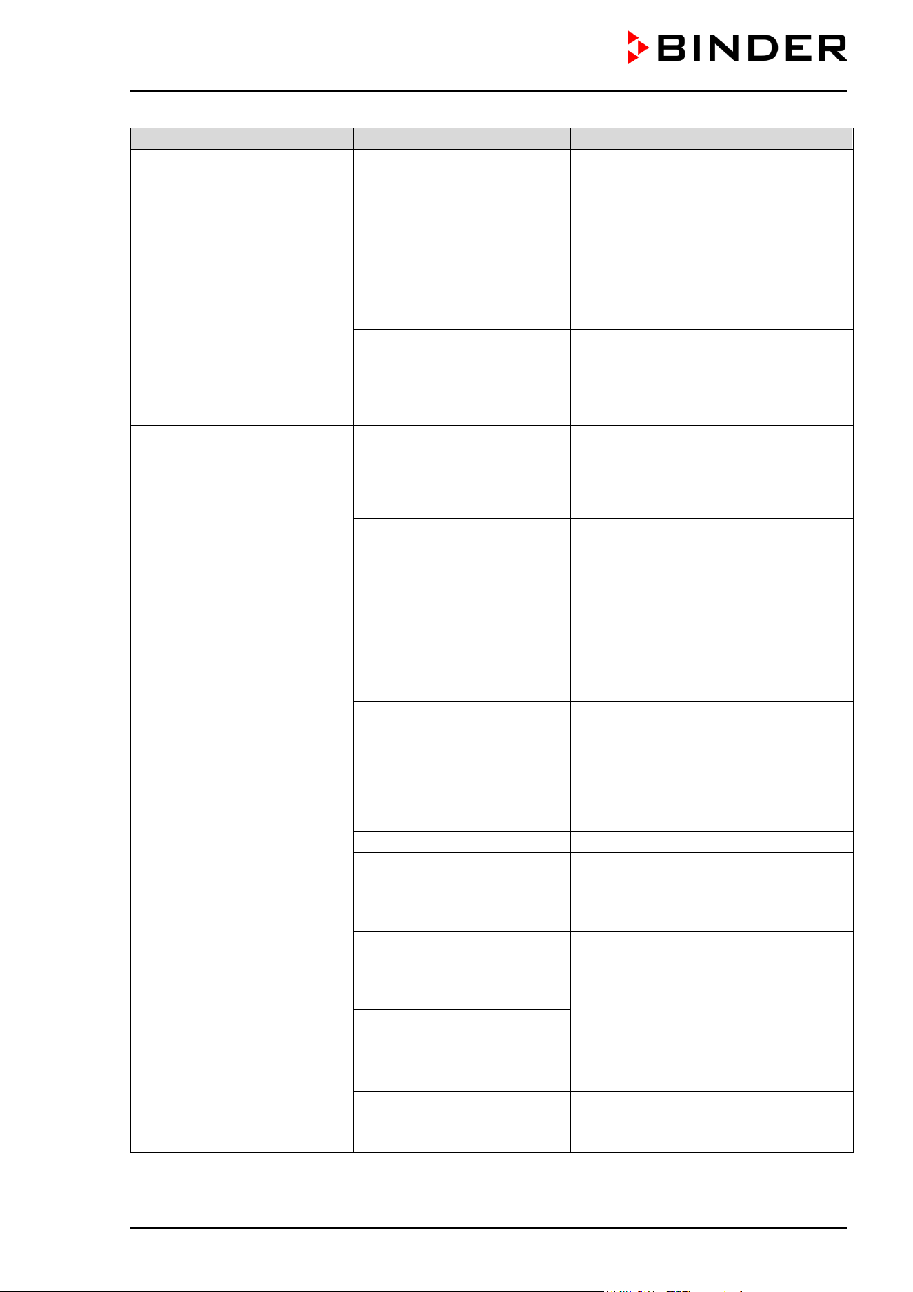
CB / CB-UL, CBF / CBF-UL (E7) 07/2022 Page 168/199
Fault description
Possible cause
Required measures
Chamber with O
2
control:
Excess O
2
concentration.
Having reached the setpoint,
O
2
exceeds the setpoint by
more than the set tolerance
range value (more than 10
min.) (O
2
control option)
Alarm message
“O
2
range”
Temporary disturbance of the
O
2
control.
Acknowledge the alarm on the
controller. Turn off the chamber. Open
the chamber doors for approx. 5
minutes. Observe the general
information for safe handling of oxygen
(chap.
1.9).. Prevent oxygen
enrichment in the ambiance of the
chamber. Turn on the chamber again.
Upon renewed alarm, contact BINDER
service.
O
2
sensor defective.
Acknowledge the alarm on the
controller. Contact BINDER Service.
Recovery time (up to 5 vol.-%
CO
2
) after doors were open for
2 minutes is < 2 minutes
CO
2
sensor system defective. Contact BINDER Service.
Too low CO
2
concentration.
Having reached the setpoint,
CO
2
falls below the setpoint by
more than the set tolerance
range value (more than 10
min.) or CO
2
doesn’t reach the
tolerance range within 3 hours
from turning on the chamber or
closing the door.
Alarm message “CO
2
range”
Temporary disturbance of the
CO
2
control.
Acknowledge the alarm on the
controller. Turn off the chamber. After
approx. 5 minutes turn on the chamber
again. Upon renewed alarm, contact
BINDER service.
CO
2
sensor defective.
Acknowledge the alarm on the
controller. Contact BINDER Service.
To replace the sensor proceed as
described in chap. 22.4.
Chamber with O
2
control:
Too low O
2
concentration.
Having reached the setpoint,
O
2
falls below the setpoint by
more than the set tolerance
range value (more than 10
min.) or O
2
doesn’t reach the
tolerance range within 3 hours
from turning on the chamber or
closing the door.
Alarm message “O
2
range”.
Temporary disturbance of the
O
2
control.
Acknowledge the alarm on the
controller. Turn off the chamber. After
approx. 5 minutes turn on the chamber
again. Upon renewed alarm, contact
BINDER service.
O
2
sensor defective.
Acknowledge the alarm on the
controller. Contact BINDER Service.
Too low gas concentration.
The concentration of CO
2
or
O
2
(chamber with O
2
control)
does not reach the adjusted
set value.
Door gaskets defective.
Replace door gaskets
Doors not closed properly.
Close door properly.
Connected gas cylinder is
empty or not opened.
Open or replace gas cylinder.
Gas cylinder is not connected
correctly.
Correctly connect the gas cylinder.
Gas hose is dirty or
obstructed.
Check the tube system for dirt
accumulation or obstruction, clean or
replace it.
Recovery time (up to 5 vol.-%
CO
2
) after doors were open for
2 minutes is > 10 minutes.
Obstructed gas supply.
Check gas supply (cylinder,
connections, hose system).
Insufficient CO
2
input
pressure
Unusually high gas
consumption.
Door gaskets defective.
Replace door gaskets
Gas sensor not adjusted.
Calibrate the sensor.
Gas sensor defective.
Contact BINDER Service
Gas fine filter not connected
correctly.
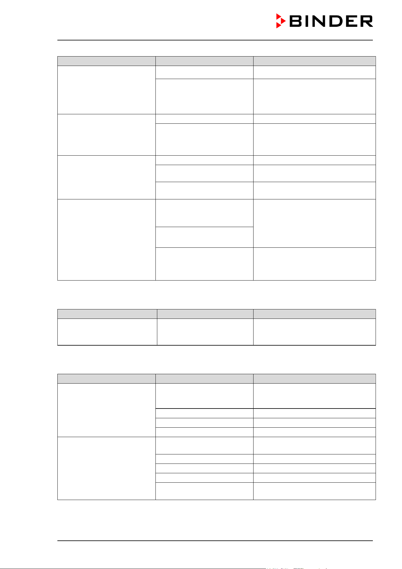
CB / CB-UL, CBF / CBF-UL (E7) 07/2022 Page 169/199
Fault description
Possible cause
Required measures
The displayed actual value of
CO
2
deviates largely compared
with a reference method.. The
pH indicator of the cell culture
medium changes its normal
color.
CO
2
control not adjusted. Calibrate and adjust CO
2
control.
CO
2
sensor defective.
Transfer the cultures to another
incubator and contact BINDER
Service. To replace the sensor
proceed as described in chap. 22.4.
Chamber with O
2
control:
The displayed actual value of
O
2
(option) deviates largely
compared with a reference
method.
O
2
control not adjusted.
Calibrate and adjust O
2
control.
O
2
sensor defective.
Transfer the cultures to another
incubator and contact BINDER
Service.
No gas control after hot-air
sterilization.
Sterilization cycle still running.
Terminate hot-air sterilization.
Information message not
confirmed.
Confirm the information message with
“Ok”.
Inner chamber temperature
above 80 °C
Let the inner chamber temperature
decrease below 80 °C.
Condensation on the glass
door and on the CO
2
sensor
head under the filter cap.
Alarm message: “CO2 sensor
not ready”.
After 6 hours with no user
reaction, this message is
replaced by the alarm
message: “CO2 sensor fault”.
Outer door open and inner
glass door closed for more
than 5 minutes
Acknowledge the alarm on the
controller. Remove the filter cap and
let it dry until there is no visible
condensation. Plug on the filter cap. If
after drying the alarm message
reappears, contact BINDER Service.
Power failure for more than 5
minutes
CO
2
sensor defective
Acknowledge the alarm on the
controller. Contact BINDER Service.
To replace the sensor proceed as
described in chap. 22.4.
22.6.5 Sterilization
Indication
Possible cause
Required measures
The sterilization is running.
Alarm message “Sterilization”.
Sterilization cycle is running
Acknowledge the alarm on the
controller. Do not open the door.
22.6.6 Humidity (CB / CB-UL)
Fault description
Possible cause
Required measures
Condensations inside the
chamber.
Permadry™ pan filled with
water when the chamber is not
operating.
Empty Permadry™ pan when the
chamber is not operating.
Door gaskets defective.
Replace door gaskets
Doors not closed properly.
Close door properly.
Humidity set too high.
Reduce humidity (chap. 6.8)
Condensation on the doors or
on the optional divided inner
door.
Chamber placed on very cold
floor.
Place the chamber on a BINDER stand
to increase the distance to the floor.
Door gaskets defective.
Replace door gaskets
Doors not closed properly.
Close door properly.
Humidity set too high.
Reduce humidity (chap. 6.8)
Door heating set too low.
Contact BINDER Service to adjust the
door heating
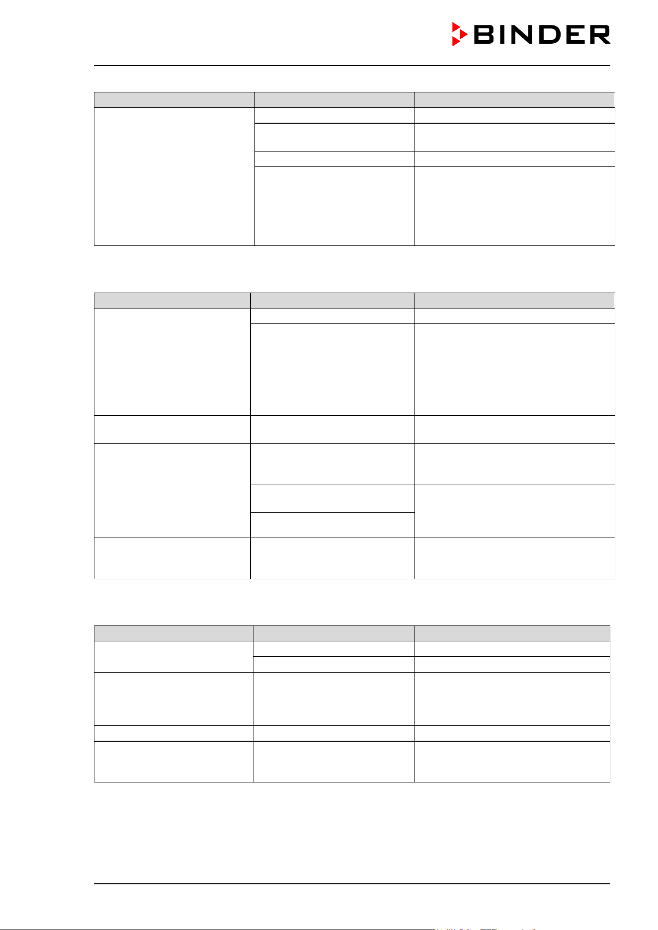
CB / CB-UL, CBF / CBF-UL (E7) 07/2022 Page 170/199
Fault description
Possible cause
Required measures
Too low humidity inside.
Humidity set too low.
Increase humidity (chap. 6.8)
Chamber door not properly
closed.
Completely close chamber door.
Door gasket defective.
Replace door gasket.
Permadry™ pan empty.
Fill the outer Permadry™ pan with
water up to the marking on the inner
pan with distilled, sterile water. The
pan must have thorough contact to the
bottom of the inner chamber, see
chap. 4.2.
22.6.7 Humidity (CBF / CBF-UL)
Fault description
Possible cause
Required measures
Humidity fluctuation:
Control accuracy of +/- 3 %
r.h. is not reached.
Door gasket defective.
Replace door gasket.
Door opened very frequently. Open doors less frequently.
Humidity fluctuation, together
with temperature fluctuation
> 1 °C with a set-point approx.
3 °C above ambient
temperature.
Place of installation too hot.
Select cooler place of installation or
contact BINDER service.
Alarm message “Humidity
system”.
Humidity module defective.
Acknowledge the alarm on the
controller. Contact BINDER service.
Alarm message “Freshwater
supply”.
Freshwater bag is empty or
contains air.
Acknowledge the alarm on the
controller. Fill the freshwater bag
correctly.
The silicon tube is not correctly
inserted into the pump.
Acknowledge the alarm on the
controller.
Place the silicon tube correctly (chap.
4.5.2).
Silicon tube kinked.
Too high humidity inside the
chamber (exceeding the set-
point)
Ambient humidity too high at
site of installation
Possible dehumidification depends on
ambient humidity. Select installation
site with lower humidity.
22.6.8 Controller
Fault description
Possible cause
Required measures
No chamber function
(dark display).
Display in standby mode.
Press on touchscreen.
Main power switch turned off.
Turn on the main power switch.
Menu functions not available.
Menu functions not available
with current authorization level.
Log in with the required higher
authorization. or contact BINDER
service to obtain an activation code
(chap. 13.6).
No access to controller
Password incorrect.
Contact BINDER service.
Chart recorder function:
measured-value memory
cleared; information lost.
New setting of storage rate or
scaling (minimum and/or
maximum) (chap. 16.2).
Change the storage rate or scaling
ONLY if the previously registered data
are no longer required.
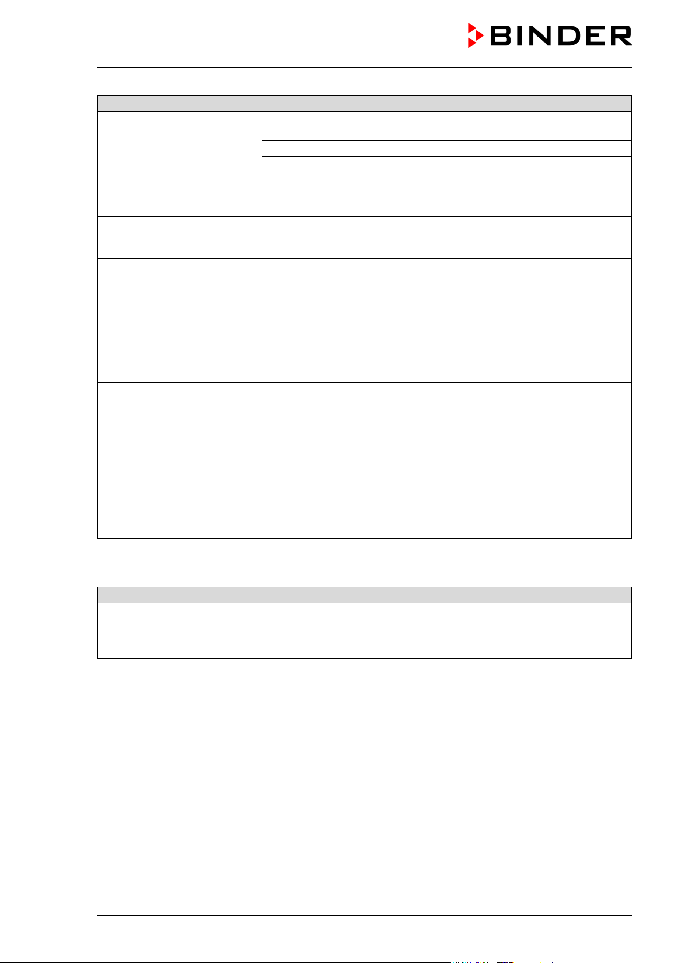
CB / CB-UL, CBF / CBF-UL (E7) 07/2022 Page 171/199
Fault description
Possible cause
Required measures
Controller does not equilibrate
to setpoints entered in Fixed
value operation mode
Controller is not in Fixed value
operation mode.
Change to Fixed value operation
mode.
CO
2
control is deactivated.
Activate CO
2
control (chap. 6.7).
Chamber with O
2
control:
O
2
control is deactivated.
Activate O
2
control (chap. 6.7).
CBF / CBF-UL: Humidity
control is deactivated.
Activate humidity control (chap. 6.7).
Controller does not equilibrate
to program set-points.
Controller is not in program
operation mode, or program
delay time is running.
Start the program again. If
appropriate, wait for the program
delay time.
Program duration longer than
programmed.
Tolerances have been
programmed.
For rapid transition phases, do NOT
program tolerance limits in order to
permit maximum speed for heating,
gas control or humidification.
Program keeps the last
program setpoint constant
while in setting “ramp”.
Program line with setting
“ramp” is incomplete.
When programming with setting
“ramp”, define the end value of the
desired cycle by adding an additional
section with a section time of at least
one second.
Ramp temperature transitions
are only realized as steps.
Setting “step” has been
selected.
Select setting “ramp”.
CBF / CBF-UL: Humidity alarm
when operating without water
supply.
Humidity control is activated.
Deactivate humidity control (chap.
6.7).
Acknowledging the alarm does
not cancel the alarm state.
Cause of alarm persists.
Remove cause of alarm. If the alarm
state continues, contact BINDER
service.
Alarm message:
- - - - or <-<-< or >->->
Sensor rupture between
sensor and controller or Pt 100
sensor defective.
Contact BINDER service.
22.6.9 Open door
Indication
Possible cause
Required measures
Outer door open (longer than
the selected alarm delay time)
Alarm message “Door open”.
Outer door open or not properly
closed.
Acknowledge the alarm on the
controller. Close the door. The
triggered zero-voltage relay alarm
contact switches back.
22.7 Sending the chamber back to BINDER GmbH
If you return a BINDER product to us for repair or any other reason, we will only accept the product upon
presentation of an authorization number (RMA number) that has previously been issued to you. An
authorization number will be issued after receiving your complaint either in writing or by telephone prior to
your sending the BINDER product back to us. The authorization number will be issued following receipt of
the information below:
• BINDER product type and serial number
• Date of purchase
• Name and address of the dealer from which you bought the BINDER product
• Exact description of the defect or fault
• Complete address, contact person and availability of that person
• Exact location of the BINDER product in your facility
• A contamination clearance certificate (chap. 26) must be faxed in advance
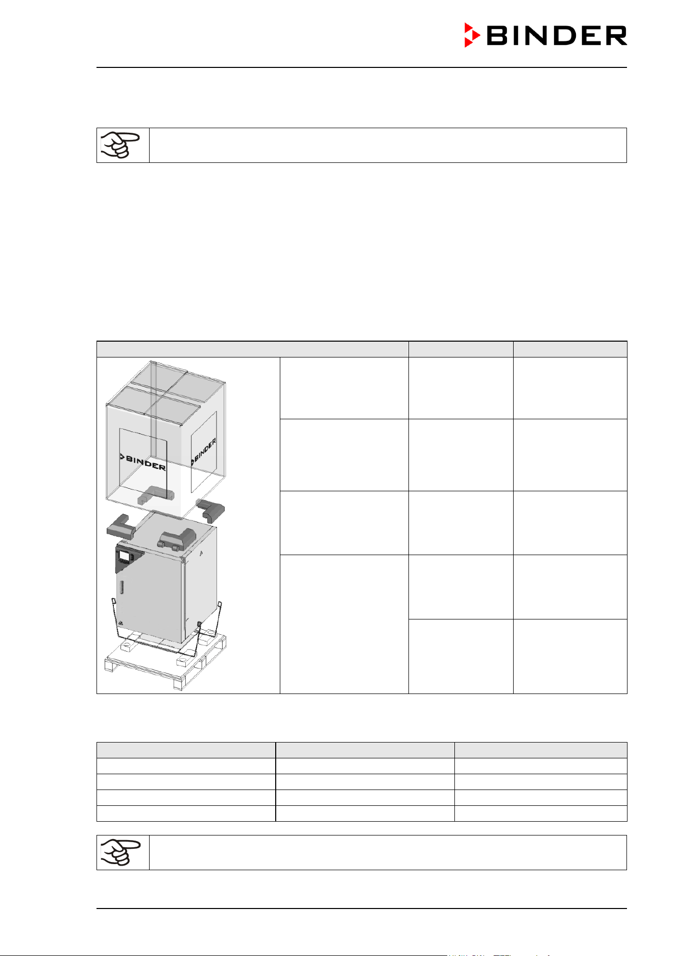
CB / CB-UL, CBF / CBF-UL (E7) 07/2022 Page 172/199
The authorization number must be applied to the packaging in such a way that it can be easily recognized
or be recorded clearly in the delivery documents.
For security reasons we cannot accept a chamber delivery if it does not carry an
authorization number.
Return address: BINDER GmbH
Abteilung Service
Gänsäcker 16
78502 Tuttlingen, Germany
23. Disposal
23.1 Disposal of the transport packing
23.1.1 Outer chamber packing
Packing element
Material
Disposal
Straps to fix packing
on pallet (no image)
Plastic Plastic recycling
Shipping box Cardboard Paper recycling
Edge stuffing, top PE foam Plastic recycling
Pallet with foamed
plastic stuffing
PE foam Plastic recycling
Solid wood (IPPC
standard)
Wood recycling
23.1.2 Packing inside the chamber and equipment
Packing element
Material
Disposal
Door protection
PE foam
Plastic recycling
Packing box equipment
Cardboard
Paper recycling
Insulating air cushion foil
PE foil
Plastic recycling
Bag for operating manuals
PE foil
Plastic recycling
If recycling is not possible, all packing parts can also be disposed of with normal waste.
CB / CB-UL, CBF / CBF-UL (E7) 07/2022 Page 173/199
23.2 Decommissioning
• Turn off the chamber at the main power switch and disconnect it from the power supply (pull the power
plug).
When switching off the main power switch, the stored parameters remain saved.
• Turn off the CO
2
supply and the O
2
/ N
2
supplies (chamber with O
2
control). Remove the gas
connections.
• CBF / CBF-UL: Empty the freshwater bag.
• Let the inner chamber sufficiently cool down after a hot-air sterilization before removing any parts.
• The Permadry™ water pan must not remain filled while the chamber is out of operation. Otherwise
condensation on the inner surfaces and the CO
2
sensor head may occur. In this case, clean and dry the
chamber with doors open for at least one hour before restarting the chamber. BINDER recommends
performing a hot air sterilization of the chamber before commissioning.
• Temporal decommissioning: See indications for appropriate storage, chap. 3.3.
• Final decommissioning: Dispose of the chamber as described in chap. 23.3 to 23.5.
• When restarting the chamber, please pay attention to the corresponding safety information.
23.3 Disposal of the chamber in the Federal Republic of Germany
According to Annex I of Directive 2012/19/EU of the European Parliament and of the Council on waste
electrical and electronic equipment (WEEE), BINDER devices are classified as “monitoring and control
instruments” (category 9) only intended for professional use“. They must not be disposed of at public
collecting points.
The chambers bear the symbol for the marking of electrical and electronic equipment
manufactured / placed on the market in the EU after 13 August 2005 and be disposed of in
separate collection according to Directive 2012/19/EU on waste electrical and electronic
equipment (WEEE) and German national law for electrical and electronic equipment (Elektro-
und Elektronikgerätegesetz, ElektroG). WEEE marking: crossed-out wheeled bin with solid
bar under. A significant part of the materia
ls must be recycled in order to protect the
environment.
At the end of the device’s service life, have the chamber disposed of according to the German national law
for electrical and electronic equipment (Elektro- und Elektronikgerätegesetz, ElektroG from 20 October
2015, BGBl. I p. 1739) or contact BINDER service who will organize taking back and disposal of the
chamber according to the German national law for electrical and electronic equipment (Elektro- und
Elektronikgerätegesetz, ElektroG from 20 October 2015, BGBl. I p. 1739).
NOTICE
Danger of violation against existing law if not disposed of properly.
Failure to comply with applicable law.
∅ Do NOT dispose of BINDER devices at public collecting points.
Have the device disposed of professionally at a recycling company which is certified
according to the German national law for electrical and electronic equipment (Elektro-
und Elektronikgerätegesetz, ElektroG from 20 October 2015, BGBl. I p. 1739).
or
Instruct BINDER Service to dispose of the device. The general terms of payment and
delivery of BINDER GmbH apply, which were valid at the time of purchasing the
chamber.
CB / CB-UL, CBF / CBF-UL (E7) 07/2022 Page 174/199
Certified companies disassemble waste (used) BINDER equipment in primary substances for recycling
according to Directive 2012/19/EU. The devices must be free from toxic, infectious or radioactive
substances in order to eliminate any health hazards to the employees of the recycling companies.
• Prior to handing the chamber over to a recycling company, it is the user’s responsibility that
it is free from toxic, infectious or radioactive substances.
• Prior to disposal, clean all introduced or residual toxic substances from the chamber.
• Prior to disposal, disinfect the chamber from all sources of infection. Be aware that sources
of infection may also be located outside the inner chamber.
• If you cannot safely remove all toxic substances and sources of infection from the chamber,
dispose of it as special waste according to national law.
• Fill out the contamination clearance certificate (chap. 26) and enclose it with the chamber.
WARNING
Danger of intoxication and infection through contamination of the chamber with
toxic, infectious or radioactive substances.
Damages to health.
∅ NEVER take a chamber contaminated with toxic substances or sources of infection for
recycling according to Directive 2012/19/EU.
Prior to disposal, remove all toxic substances and sources of infection from the
chamber.
A chamber from which all toxic substances or sources of infection cannot be safely
removed must be considered as “special” waste according to national law. Dispose of it
accordingly.
The main board of the chamber includes a lithium cell. As the end user, you are legally obliged to return
used batteries. Old batteries and rechargeable batteries must not be disposed of with household waste.
They can be handed in free of charge at the community's public collection points and wherever batteries
and accumulators of the type in question are sold.
23.4 Disposal of the chamber in the member states of the EU except for the
Federal Republic of Germany
According to Annex I of Directive 2012/19/EU of the European Parliament and of the Council on waste
electrical and electronic equipment (WEEE), BINDER devices are classified as “monitoring and control
instruments” (category 9) only intended for professional use“. They must not be disposed of at public
collecting points.
The chambers bear the symbol for the marking of electrical and electronic equipment
manufactured / placed on the market in the EC after 13 August 2005 and be disposed of in
separate collection according to the Directive 2012/19/EU on waste electrical and electronic
equipment (WEEE). WEEE marking: crossed-out wheeled bin with solid bar under.
At the end of the device’s service life, notify the distributor who sold you the device, who will
take back and dispose of the chamber according to the Directive 2012/19/EU on waste
electrical and electronic equipment (WEEE).
CB / CB-UL, CBF / CBF-UL (E7) 07/2022 Page 175/199
NOTICE
Danger of violation against existing law if not disposed of properly.
Failure to comply with applicable law.
∅ Do NOT dispose of BINDER devices at public collecting points.
Have the device disposed of professionally at a recycling company that is certified
according to conversion of the Directive 2012/19/EU into national law.
or
Instruct the distributor who sold you the device to dispose of it. The agreements apply
that were agreed
with the distributor when purchasing the chamber (e.g. his general
terms of payment and delivery).
If your distribu
tor is not able to take back and dispose of the chamber, please contact
BINDER service.
Certified companies disassemble waste (used) BINDER equipment in primary substances for recycling
according to Directive 2012/19/EU. The devices must be free from toxic, infectious or radioactive
substances in order to eliminate any health hazards to the employees of the recycling companies.
• Prior to handing the chamber over to a recycling company, it is the user’s responsibility that
it is free from toxic, infectious or radioactive substances.
• Prior to disposal, clean all introduced or residual toxic substances from the chamber.
• Prior to disposal, disinfect the chamber from all sources of infection. Be aware that sources
of infection may also be located outside the inner chamber.
• If you cannot safely remove all sources of infection and toxic substances from the chamber,
dispose of it as special waste according to national law.
• Fill out the contamination clearance certificate (chap. 26) and enclose it with the chamber.
WARNING
Danger of intoxication and infection through contamination of the chamber with
toxic, infectious or radioactive substances.
Damages to health.
∅ NEVER take a chamber contaminated with toxic substances or sources of infection for
recycling according to Directive 2012/19/EU.
Prior to disposal, remove all toxic substances and sources of infection from the
chamber.
A chamber from which all
toxic substances or sources of infection cannot be safely
removed must be considered as “special” waste according to national law. Dispose of it
accordingly.
The main board of the chamber includes a lithium cell. The disposal of batteries within the EU must be
carried out in accordance with the current EU directives as well as national, regional and local
environmental protection regulations.
CB / CB-UL, CBF / CBF-UL (E7) 07/2022 Page 176/199
23.5 Disposal of the chamber in non-member states of the EU
NOTICE
Danger of violation against existing law if not disposed of properly.
Failure to comply with applicable law. Alteration of the environment.
For final decommissioning and disposal of the chamber, please contact BINDER service.
Follow the statutory regulations for appropriate, environmentally friendly disposal.
The main board of the chamber includes a lithium cell. Used batteries must be disposed of properly. Please
ensure that you dispose of the battery in accordance with the regulations in force in your country.
24. Technical description
24.1 Factory calibration and adjustment
This chamber was calibrated and adjusted in the factory. Calibration and adjustment were performed using
standardized test instructions, according to the QM DIN EN ISO 9001 system applied by BINDER (certified
since December 1996 by TÜV CERT). All test equipment used is subject to the administration of
measurement and test equipment that is also a constituent part of the BINDER QM DIN EN ISO 9001
systems. They are controlled and calibrated to a DKD-Standard at regular intervals.
A record of this calibration and adjustment is part of the BINDER test certificate of the chamber.
Adjustment in factory:
• Temperature: 37 °C / 98.6°F measured in the center of the usable volume
• CO
2
: 0 vol.-% CO
2
(100 vol.-% N
2
) and 5 vol.-% CO
2
(analyzed test gas directly exposed to the sensor
head)
• O
2
(chamber with O
2
control): 0 vol.-% O
2
(100 vol.-% N
2
, analyzed test gas directly exposed to the
sensor head) and 20.9 vol.-% O
2
(ambient air).
• Humidity (CBF / CBF-UL): 93 % r.h.
Repeated calibrations are recommended in periods of 12 months.
For temperature and humidity calibration and adjustment, BINDER service uses electronic measuring and
display devices traceable to an acknowledged standards/calibration institution (DKD or PTB for Germany)
with a valid calibration certificate.
Test gases with an analyzed concentration serve to calibrate the sensor systems for CO
2
and O
2
(chamber
with O
2
control). The sensor heads are exposed directly to the test gas.
24.2 Over current protection
The chamber is protected by a chamber-protection against over current, accessible from the outside. It is
located at the rear of the chamber below the strain relief of the power cord. The fuse holder is equipped
with a fuse clip 5mm x 20 mm (CB) or 6.3 x32 mm (CB-UL). Replace this fuse only with a substitute of the
same ratings. Refer to the technical data of the respective device type. If this fuse is blown, please inform
an electronic engineer or BINDER service.
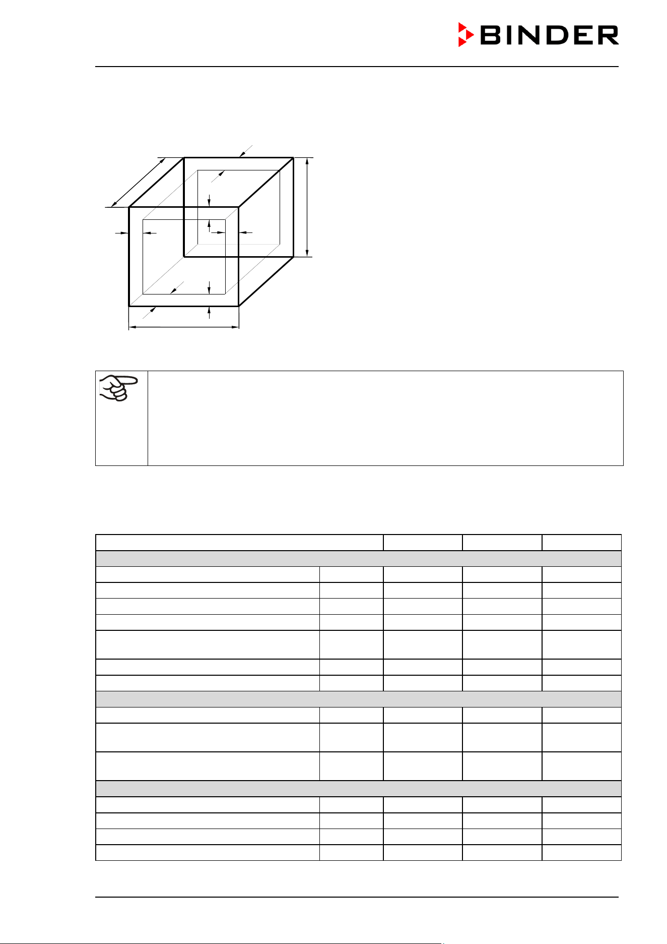
CB / CB-UL, CBF / CBF-UL (E7) 07/2022 Page 177/199
24.3 Definition of usable volume
The usable volume illustrated below is calculated as follows:
c
c
b
a
C
B
A
b
a
A, B, C = internal dimensions (W, H, D)
a, b, c = wall separation
a = 0.1*A
b = 0.1*B
c = 0.1*C
V
USE
= (A - 2 * a) * (B - 2 * b) * (C - 2 * c)
Figure 53: Determination of the usable volume
The technical data refers to the defined usable volume.
Do NOT place samples outside this usable volume.
Do NOT load this volume by more than half to enable sufficient airflow inside the chamber.
Do NOT divide the usable volume into separate parts with large area samples.
Do NOT place samples too close to each other in order to permit circulation between them
and thus obtain a homogenous distribution of temperature, CO
2
, O
2
(chamber with O
2
control),
and humidity.
24.4 Technical data
Chamber size
56
170
260
Exterior dimensions
Width, net
mm / inch
520 / 20.47
680 / 26.77
740 / 29.13
Height including feet
mm / inch
675 / 26.57
870/ 34.25
1025 / 40.35
Depth, net
mm / inch
550 / 21.65
715 / 28.15
775 / 30.51
Depth plus door handle, I-triangle
mm / inch
55 / 2.16
55 / 2.16
55 / 2.16
Depth plus power connection and gas
connection
mm / inch 10 / 0.39 10 / 0.39 10 / 0.39
Wall clearance rear (minimum)
mm / inch
100 / 3.94
100 / 3.94
100 / 3.94
Wall clearance side (minimum)
mm / inch
50 / 1.97
50 / 1.97
50 / 1.97
Doors
Quantity of outer doors
1
1
1
Quantity of inner doors (inner glass door or
divided inner door)
1 1 1
Quantity of individual inner glass doors
(with divided inner door)
4 6 8
Interior dimensions
Width
mm / inch
400 / 15.75
560 / 22.05
620 / 24.41
Height
mm / inch
400 / 15.75
600 / 23.62
750 / 29.53
Depth
mm / inch
330 / 12.99
500 / 19.69
560 / 22.05
Interior volume
L / cu.ft.
53 / 1.9
170 / 6.0
260 / 9.2
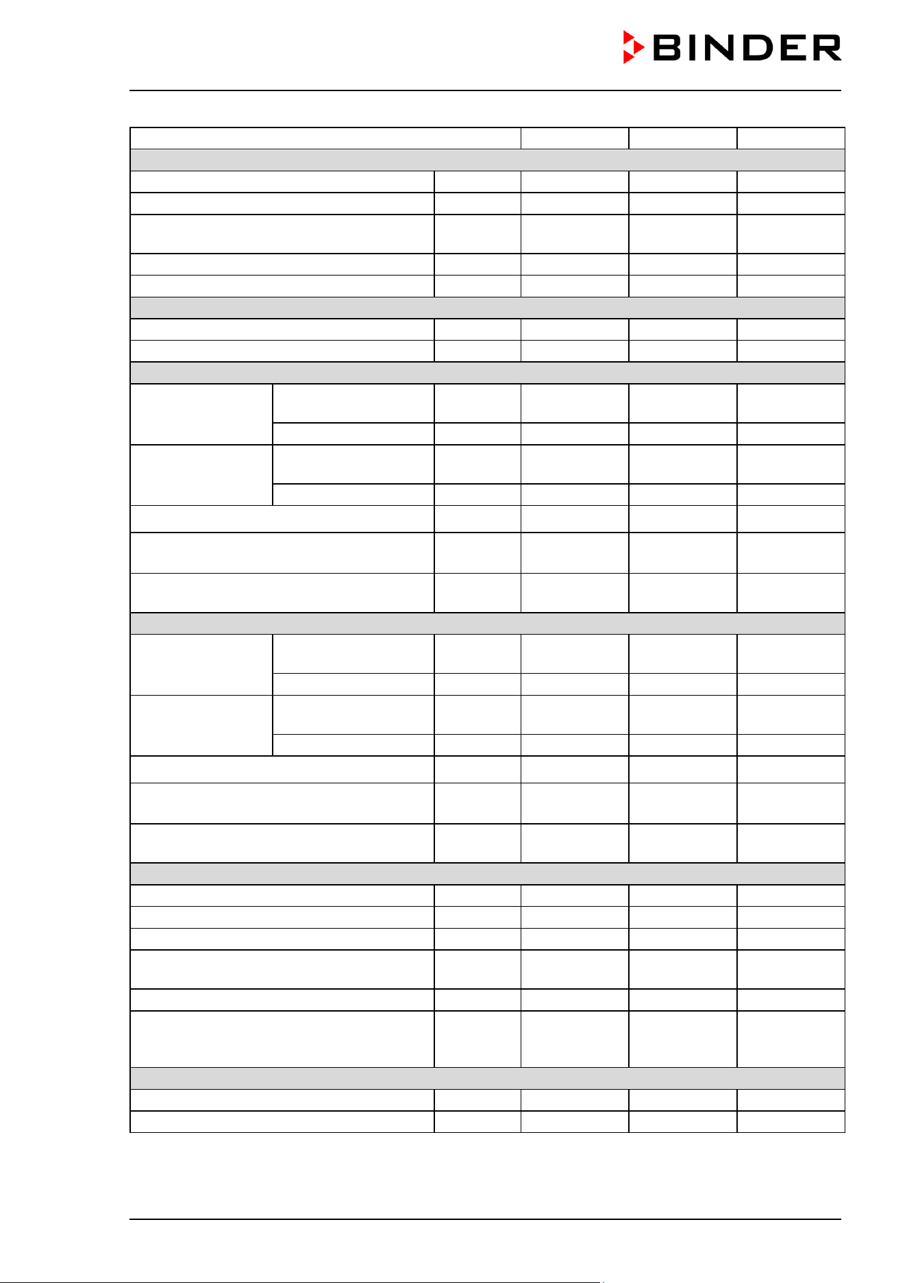
CB / CB-UL, CBF / CBF-UL (E7) 07/2022 Page 178/199
Chamber size
56
170
260
Shelves
Number of shelves, regular
2
3
4
Number of shelves, max.
3
6
8
Size of shelf (external) Width x Depth
mm x mm
inch x inch
396 x 289
15.59 x 11.38
551 x 442
21.69 x 17.40
614 x 502
24.17 x 19.76
Maximum load per shelf
Kg / lbs.
10 / 22
10 / 22
10 / 22
Permitted total load
Kg / lbs
30 / 66
30 / 66
40 / 88
Weight
Weight (empty) CB / CB-UL
Kg / lbs
53 / 116.9
95 / 209.4
121 / 266.8
Weight (empty) CBF / CBF-UL
Kg / lbs
---
97 / 213.8
122 / 268.9
CB / CB-UL temperature data
Temperature range
from … degree above
ambient
°C / °F 4 / 7.2 4 / 7.2 5 / 9.0
up to
°C / °F
60 / 140
60 / 140
60 / 140
Temperature range,
chamber with O
2
control
from … degree above
ambient
°C / °F 6 / 10.8 6 / 10.8 6 / 10.8
up to
°C / °F
60 / 140
60 / 140
60 / 140
Temperature fluctuation at 37 °C / 98.6 °F
± K 0.1 0.1 0.1
Temperature uniformity (variation)
at 37 °C/ 98.6 °F
± K 0.4 0.3 0.4
Recovery time after door was opened for
30 sec at 37 °C / 98.6 °F
minutes 5 6 6
CBF / CBF-UL temperature data
Temperature range
from … degree above
ambient
°C / °F --- 5 / 9 6 / 10.8
up to
°C / °F
---
60 / 140
60 / 140
Temperature range,
chamber with O
2
control
from … degree above
ambient
°C / °F --- 7 / 12.6 6 / 10.8
up to
°C / °F
---
60 / 140
60 / 140
Temperature fluctuation at 37 °C / 98.6 °F
± K --- 0.1 0.1
Temperature uniformity (variation)
at 37 °C/ 98.6 °F
± K --- 0.4 0.4
Recovery time after door was opened for
30 sec at 37 °C / 98.6 °F
minutes --- 6 6
CO
2
data
CO
2
range
vol.-% CO
2
0 to 20
0 to 20
0 to 20
Setting accuracy
vol.-% CO
2
0.1
0.1
0.1
CO
2
fluctuation
vol.-% CO
2
0.1
0.1
0.1
Recovery time after door was opened for
30 sec at 5 vol.-% CO
2
minutes 5 5 5
CO
2
measurement
IR
IR
IR
Connection hose nozzle DN6 for CO
2
connection to the chamber for hose with
internal diameter
mm / inch 6 / 0.24 6 / 0.24 6 / 0.24
Humidity data
CB / CB-UL humidity range
% r.h.
90 to 95
90 to 95
90 to 95
CBF / CBF-UL humidity range
% r.h.
---
50 to 95
50 to 95
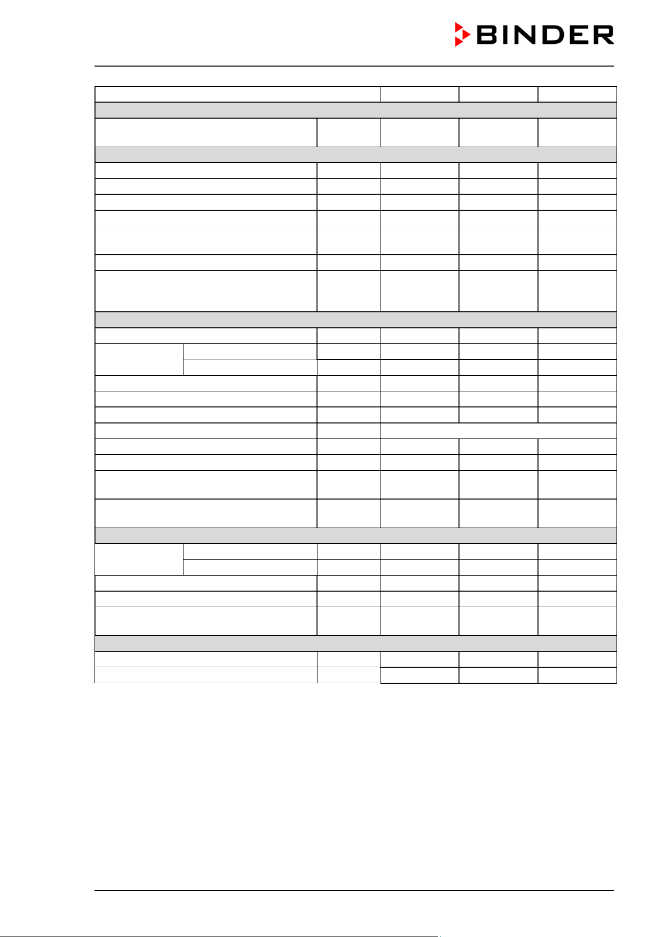
CB / CB-UL, CBF / CBF-UL (E7) 07/2022 Page 179/199
Chamber size
56
170
260
Humidity data (continued)
Recovery time after door was opened for
30 sec at 90 % r.h. (CBF / CBF-UL)
minutes --- 12 15
O
2
Data (chamber with O
2
control)
O
2
range (regular hypoxic control range)
vol.-% O
2
0.2 to 20
0.2 to 20
0.2 to 20
O
2
range (optional alternative control range)
vol.-% O
2
10 to 95
10 to 95
10 to 95
Setting accuracy with inlet pressure 2 bar
vol.-% O
2
0.1
0.1
0.1
O
2
fluctuation
vol.-% O
2
0.1
0.1
0.1
Recovery time after door was opened for
30 sec at 5 vol.-% O
2
minutes 5 10 15
O
2
measurement
ZrO
2
ZrO
2
ZrO
2
Connection hose nozzle DN6 for O
2
/N
2
connection to the chamber for hose with
internal diameter
mm / inch 6 / 0.24 6 / 0.24 6 / 0.24
Electrical data
IP system of protection acc. to EN 60529
IP
20
20
20
Nominal voltage
(+/-10 %)
at 50 Hz power frequency
V
200-230
200-230
200-230
at 60 Hz power frequency
V
200-230
200-230
200-230
Current type
1N~
1N~
1N~
CB / CB-UL nominal power
kW
0.80
1.30
1.50
CBF / CBF-UL nominal power
kW
---
1.60
1.60
Power plug (IEC connector plug)
Grounded plug IEC 7/7
Installation category acc. to IEC 61010-1
II
II
II
Pollution degree acc. to IEC 61010-1
2
2
2
Chamber fuse 4x20mm / 250V / time-lag
(T), external
Amp 10 10 10
Additional temperature fuse class 1 (DIN
12880), internal
°C 240 240 240
Different electrical data for CB-UL / CBF-UL constructed for the USA and Canada
Nominal voltage
(+/-10 %)
at 50 Hz power frequency
V
100-120
100-120
100-120
at 60 Hz power frequency
V
100-120
100-120
100-120
Current type
1N~
1N~
1N~
Power plug
NEMA
5-20P
5-20P
5-20P
Chamber fuse 5x20mm / 250V / time-lag
(T), external
Amp 12.5 16 16
Environment-specific data
Noise level (mean value)
dB (A)
41
41
41
Energy consumption at 37 °C/ 98.6 °F
Wh/h
45
55
65
Notes:
• The recovery times of the gas concentrations inside the chamber after the door is opened coincide with
a connection pressure of 2.0 bar / 29 psi. Decreasing supply pressure results in longer recovery times.
• The specified recovery times can be observed with a door opening of up to 60s. If the outer door is left
open for more than 3 minutes, all heaters are deactivated. It is then necessary to let the chamber
equilibrate again.
All technical data is specified for unloaded chambers with standard equipment at an ambient temperature
of 22 +/- 3 °C / 71.6 +/- 5.4 °F and a power supply voltage fluctuation of +/-10%. Technical data is
determined in accordance to BINDER Factory Standard Part 2:2015 and DIN 12880:2007.
All indications are average values, typical for chambers produced in series. We reserve the right to
change technical specifications at any time.
CB / CB-UL, CBF / CBF-UL (E7) 07/2022 Page 180/199
CBF / CBF-UL: Bringing a source of humidity into the inner chamber will affect the minimum
humidity specification
24.5 Equipment and Options (extract)
To operate the chamber, use only original BINDER accessories or accessories / components
from third-party suppliers authorized by BINDER. The user is responsible for any risk arising
from using unauthorized accessories.
Regular equipment
Multifunction touchscreen controller MB2 for temperature, CO
2
, O
2
(chamber with O
2
control) and
humidity (CBF / CBF-UL)
CO
2
infra-red absorption measuring system
Silicone jacket heating
Hot-air auto sterilization
Gas mixing head
Permadry™ humidity system
Weldless deep-drawn polished inner chamber made of stainless steel 1.4301/V2A, polished
FailSafe – Electronic error auto-diagnosis system
Zero-voltage relay alarm output with DIN socket (6 poles), DIN plug included
Lockable door
Tightly closing inner glass door
3 perforated shelves, stainless steel 1.4301/V2A
Overtemperature safety controller class 3.1 acc. to DIN 12880:2007
CBF / CBF-UL: Microprocessor controlled humidifying system
Chamber with O
2
control: O
2
control in the hypoxic control range 0.2 to 20 vol. % O
2
.
Ethernet interface for computer communication
Options / accessories
Perforated shelf, stainless steel
Perforated shelf, full copper
Chamber with O
2
control: Alternative control range 10 to 95 vol. % O
2
Divided inner door with cell therapy compartmentation, stainless steel, 4 times (size 56), 6 times (size
170), 8 times (size 260)
Shelves for divided inner door, stainless steel
Partition wall for cell therapy compartmentation
Quick sample access
Stacking stand with castors lockable by breaks (incubator size 170 / 210)
Stacking adapter for direct, thermally decoupled stacking
Base with castors
Stacking adapter for combination C / C-UL 150 on top of CB / CB-UL / CBF / CBF-UL 170
Silicone access ports closable with 2 silicone plugs
BINDER Gas Supply Service: External CO
2
bottle changer for CO
2
, O
2
,
or N
2
Connection kit for CO
2
, O
2
or
N
2
cylinder
Water tight internal socket 230 V (max. 3 A), with turn-off switch (available via BINDER INDIVIDUAL
Customized Solutions)
Analog output temperature and CO
2
4-20 mA 4-20mA with DIN socket (6 poles), DIN plug included
BINDER Pure Aqua Service
Cartridge for BINDER Pure Aqua Service
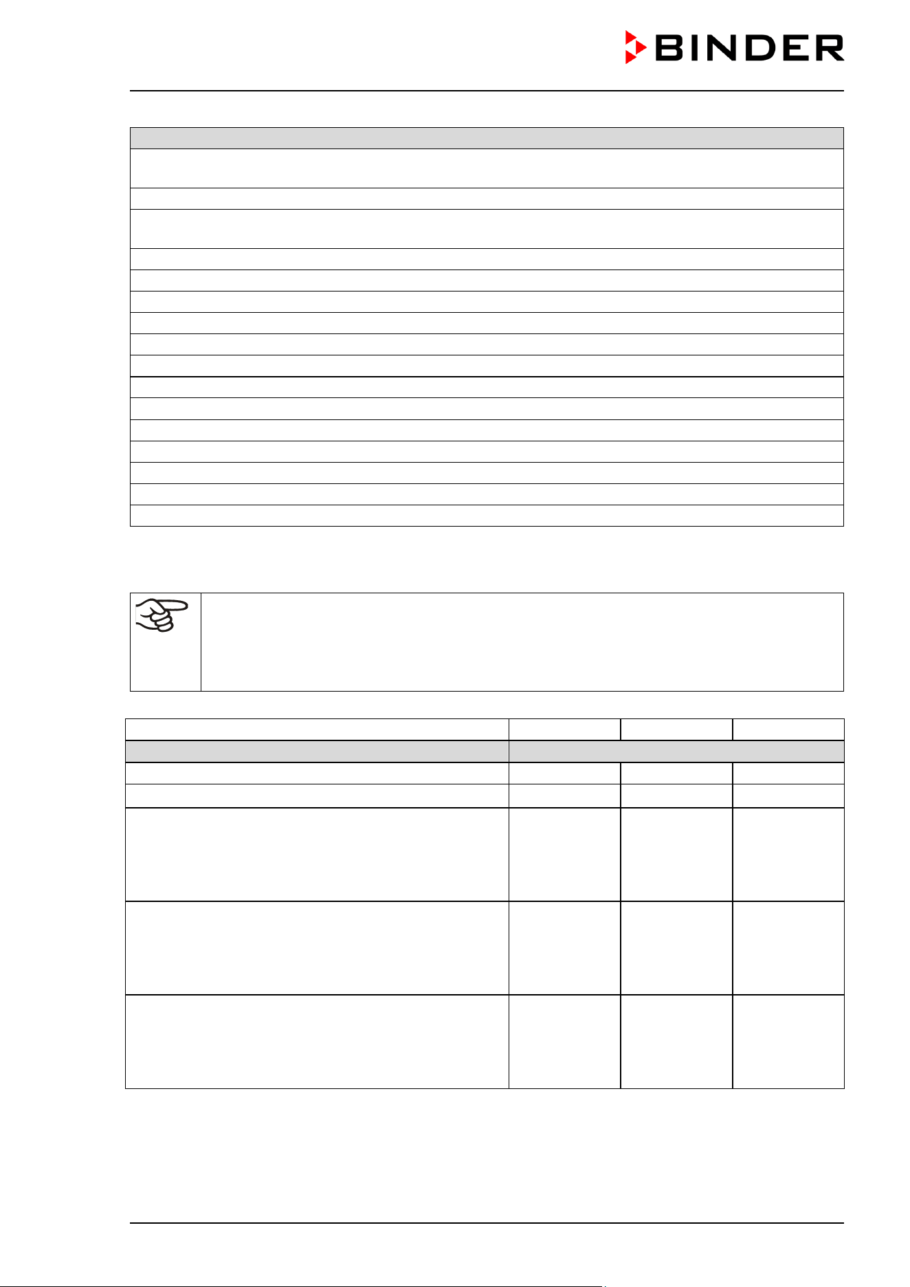
CB / CB-UL, CBF / CBF-UL (E7) 07/2022 Page 181/199
Options / accessories
Cleaning kit (neutral cleaning agent, disinfection spray and lint-free disposable wipes, gloves and
goggles)
CELLROLL roller system with set of connection cables for extra-low voltage access port
Access port (8-pin) for extra-low voltage (ELV) with LEMO socket (can be covered) and LEMO
connector, maximum power rating 24VAC/DC – 2.5 Amp
Gas fine filter with two connection pieces
CBF / CBF-UL: Freshwater bag (0.9 liters / 0.32 cu.ft.)
CBF / CBF-UL: Tubular bag set incl. accessories. Set with 3 or 12 tubular bags (annual demand)
CBF / CBF-UL: Humidification water set incl. accessories
CBF / CBF-UL: Water container set incl. accessories
Qualification folder
Calibration of temperature including certificate
Calibration of CO
2
including certificate
Spatial temperature measurement including certificate
Spatial temperature measurement acc. to DIN 12880 including certificate
Chamber with O
2
control: Calibration of O
2
including certificate
CBF / CBF-UL: Calibration of humidity including certificate
CBF / CBF-UL: Spatial temperature and humidity measurement including certificate
24.6 Accessories and spare parts (extract)
BINDER GmbH is responsible for the safety features of the chamber only, provided skilled
electricians or qualified personnel authorized by BINDER perform all maintenance and repair,
and if components relating to chamber safety are replaced in the event of failure with original
spare parts. The user is responsible for any risks arising from using unauthorized
accessories/components.
Chamber size
56
170
260
Description
Art. no.
Perforated shelf, stainless steel
6004-0136
6004-0137
6004-0197
Perforated shelf, full copper
---
6004-0233
---
Divided inner door with cell therapy compartmentation
Variant 8612
-0029
•
4 inner doors
•
2 shelf levels with one partition wall each
Door hinged
right:
8012-2023
Door hinged
left: 8012-2026
--- ---
Divided inner door with cell therapy compartmentation
Variant 8612
-0030
•
6 inner doors
•
3 shelf levels with one partition wall each
---
Door hinged
right:
8012-2024
Door hinged
left: 8012-2027
---
Divided inner door with cell therapy compartmentation
Variant 8612
-0031
•
8 inner doors
•
4 shelf levels with one partition wall each
--- ---
Door hinged
right:
8012-2025
Door hinged
left: 8012-2028
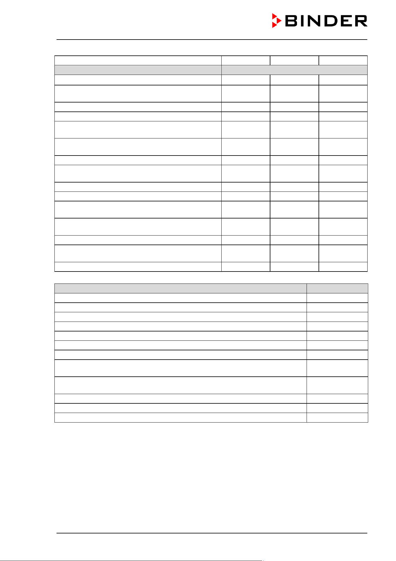
CB / CB-UL, CBF / CBF-UL (E7) 07/2022 Page 182/199
Chamber size
56
170
260
Description
Art. no.
Partition wall for cell therapy compartmentation
4020-1218 4020-1219 4020-1220
Divided shelves (1 level) for divided inner door, stainless
steel
--- 6004-0226 6004-0227
Extra-deep shelf for divided inner door, stainless steel
6004-0120
---
---
Door gasket for outer chamber door
6005-0294
6005-0275
6005-0296
Door gasket for inner glass door or for divided inner
door
6005-0312 6005-0508 6005-0314
Door gasket for individual glass door of divided inner
door
6005-0311 6005-0293 6005-0305
Individual glass door of divided inner door, complete
6005-0135
8010-0110
8010-0116
Flat stacking adapter for direct, thermally decoupled
stacking
9051-0038 9051-0035 9051-0039
Stacking stand with castors lockable by breaks
---
9051-0040
9051-0041
Base with castors
9051-0043
9051-0028
9051-0044
Stacking adapter for combination C / C-UL150/160/170
on top of CB / CB-UL / CBF / CBF-UL 170
--- 9051-0027 ---
CELLROLL roller system with set of connection cables
and extra-low voltage access port
--- 8012-0571 8012-0572
Permadry™ water pan, stainless steel
6006-0626
4022-0081
6006-0441
Permadry™ water pan, stainless steel, with divided
inner door option
6006-0666 --- ---
Permadry™ water pan, full copper
---
4022-0086
---
Description
Art. no.
Plug for optional silicon access port d30
6016-0035
Gas cylinder connection kit for CO
2
8012-0014
Gas cylinder connection kit for O
2
8012-0015
Gas cylinder connection kit for N
2
8012-0016
Chamber fuse 5x20mm 250 V 10 A time-lag (T)
5006-0088
Chamber fuse 6.3x32mm 250V 12.5 A time-lag (T) for cUL version only
5006-0096
CO
2
sensor
5002-0078
O
2
sensor for chamber with regular equipment: hypoxic control range 0.2 up to 20
vol.-% O
2
5002-0084
O
2
sensor for chamber with O
2
control with optional alternative control range 10 up to
95 vol.-% O
2
5002-0085
CBF / CBF-UL : Humidity sensor
5002-0077
Gas fine filter with two connection pieces
8009-0369
CBF / CBF-UL : Fresh water bag (0.9 liters / 0.32 cu.ft.)
6002-0626
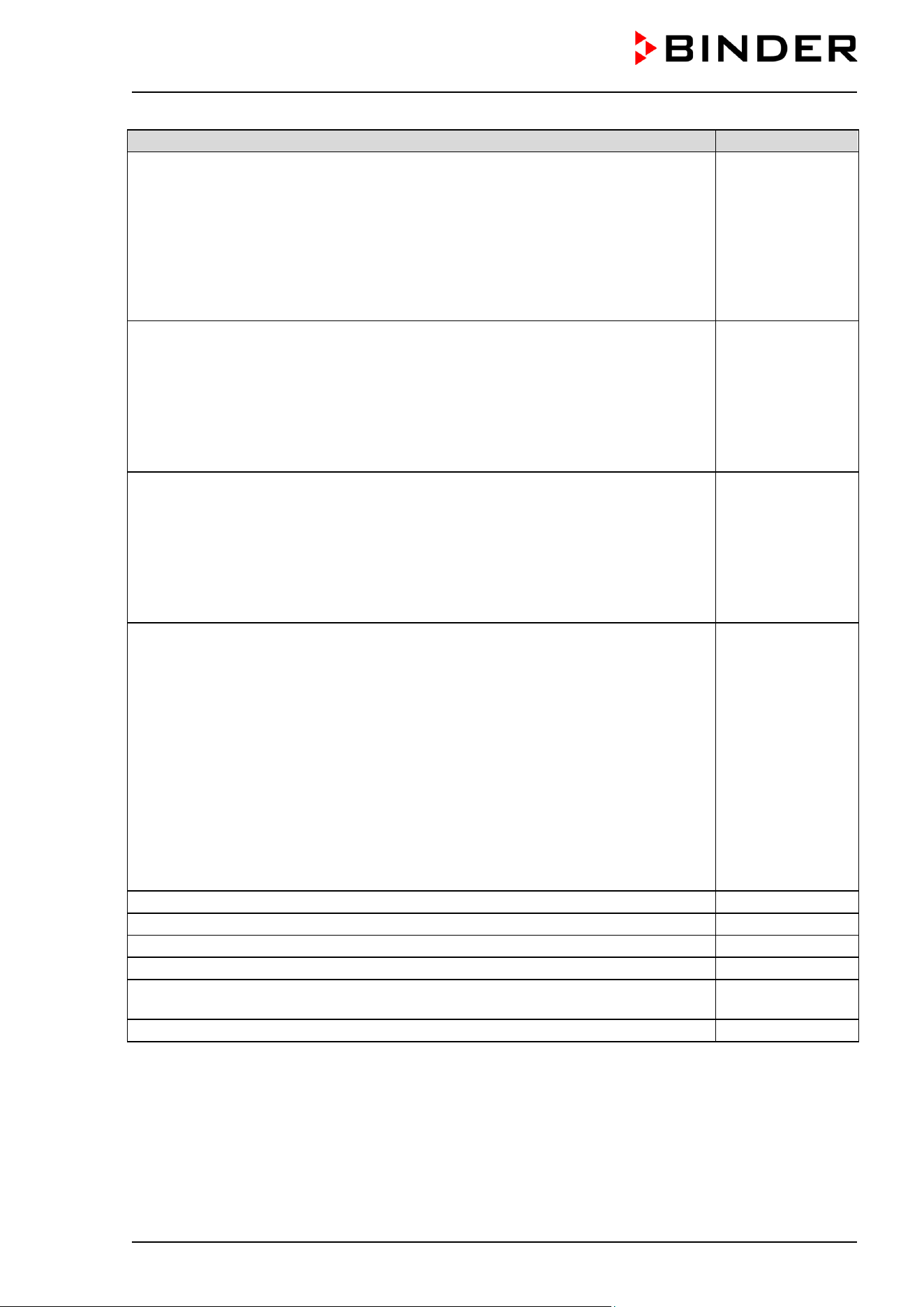
CB / CB-UL, CBF / CBF-UL (E7) 07/2022 Page 183/199
Description
Art. no.
CBF / CBF-UL : Bag set incl. accessories with 3 empty tubular bags (included with
delivery):
• 3 empty tubular bags (art.no. 6002-0626. 6002-0626)
• 3 two-piece tube connectors with 3-5mm nozzles (art.no. 6009-0322)
• 3 two-piece tube connectors with 5-7mm nozzles (art.no. 6009-0323)
• 3 gas fine filters (sterile filter) (art.no. 6014-0012)
• 6 m silicone tube (DN 3mm) (art.no. 6008-0267)
•
1m filling tube (DN 10 mm) (art.no. 6008-0268)
8009-1083
CBF / CBF-UL : Bag set incl. accessories (annual demand):
• 12 empty tubular bags (art.no. 6002-0626. 6002-0626)
• 3 two-piece tube connectors with 3-5mm nozzles (art.no. 6009-0322)
• 3 two-piece tube connectors with 5-7mm nozzles (art.no. 6009-0323)
• 12 gas fine filters (sterile filter) (art.no. 6014-0012)
• 6 m silicone tube (DN 3mm) (art.no. 6008-0267)
•
1m filling tube (DN 10 mm) (art.no. 6008-0268)
8009-1058
CBF / CBF-UL : Humidification water set incl. accessories (annual demand):
• 10 one-liter bottles, prefilled with sterile, deionized water (art.no. 1007-0314)
• 3 spike connectors (transfer sets) for sterile liquids (art.no. 6007-0131)
• 3 two-piece tube connectors with 3-5mm nozzles (art.no. 6009-0322)
• 2 m silicone tube (DN 3mm) (art.no. 6008-0267)
• 3 gas fine filters (sterile filter) (art.no. 6014-0012)
• 20 cm silicone tube (DN 6 mm) (art.no. 6008-0009)
8009-1104
CBF / CBF-UL : Water container set incl. accessories (annual demand):
•
Magnetic can holder adjustable in height, consisting of magnetic holder (art.no.
8022-0009) and water can support (art.no. 4021-0724)
• Water can, 10 l (art.no. 6011-0192)
• Hose coupling with aqua stop (art.no. 6002-0637)
• Angular coupling plug with aqua stop (art.no. 6002-0638)
• 12 gas fine filters (sterile filter) (art.no. 6014-0012)
• 10 m silicone tube (DN 3mm) (art.no. 6008-0267) to the pump or via T-
type tube
connectors to further chambers
• 50 cm silicone tube, d10 x 2 (art.no. 6008-0268)
• Reducing connector (tube connector 4/9 mm) (art.no. 6009-0308)
• 4 wire tension clamps (art.no. 6009-0281) (2 spare parts)
•
3 T-type tube connectors (T-Pieces), 4mm (art.no. 6009-0318)
8009-1128
CBF / CBF-UL : 1m silicone tube (DN 3mm)
6008-0267
CBF / CBF-UL : Pump head
5013-0204
CBF / CBF-UL : BINDER Pure Aqua Service
8012-0759
CBF / CBF-UL : Cartridge for BINDER Pure Aqua Service
6011-0165
Cleaning kit (neutral cleaning agent, disinfection spray and lint-free disposable
wipes, protective gloves and goggles)
8012-0503
Neutral cleaning agent, 1 kg
1002-0016
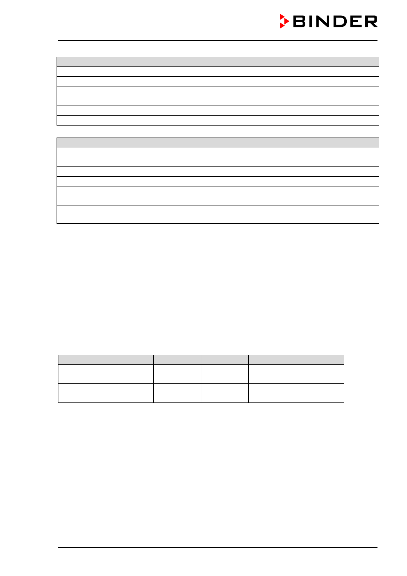
CB / CB-UL, CBF / CBF-UL (E7) 07/2022 Page 184/199
Validation service
Art. no.
Qualification folder IQ-OQ (printed version)
7007-0001
Qualification folder IQ-OQ (digital version)
7057-0001
Qualification folder IQ-OQ-PQ (printed version)
7007-0005
Qualification folder IQ-OQ-PQ (digital version)
7057-0005
Execution of IQ-OQ
DL410200
Execution of IQ-OQ-PQ
DL440500
Calibration service
Art. no.
Calibration of temperature including certificate
8012-1132
Calibration of temperature and CO
2
including certificate
8012-1235
Calibration of O
2
including certificate (chamber with O
2
control)
8012-0229
Spatial temperature measurement including certificate (15-18 measuring points)
8012-1571
Spatial temperature measurement including certificate (9 measuring points)
8012-1550
Spatial temperature measurement including certificate (27 measuring points)
8012-1592
Spatial temperature and humidity measurement including certificate (27 measuring
points for temperature, 1 measuring point for humidity)
8012-0924
For information on components not listed here, please contact BINDER Service.
24.7 Important conversion data for non-SI units
1 ft = 0.305 m
1 m = 100 cm = 3.28 ft = 39.37 inch
1 mbar = 0.0145 psi
24.8 Conversion table for gas inlet pressures, bar – psi
bar
psi
bar
psi
bar
psi
1
14.5
3
43.5
5
72.5
1.5
21.7
3.5
50.7
5.5
79.7
2
29.0
4
58.0
6
87.0
2.5
36.3
4.5
65.2
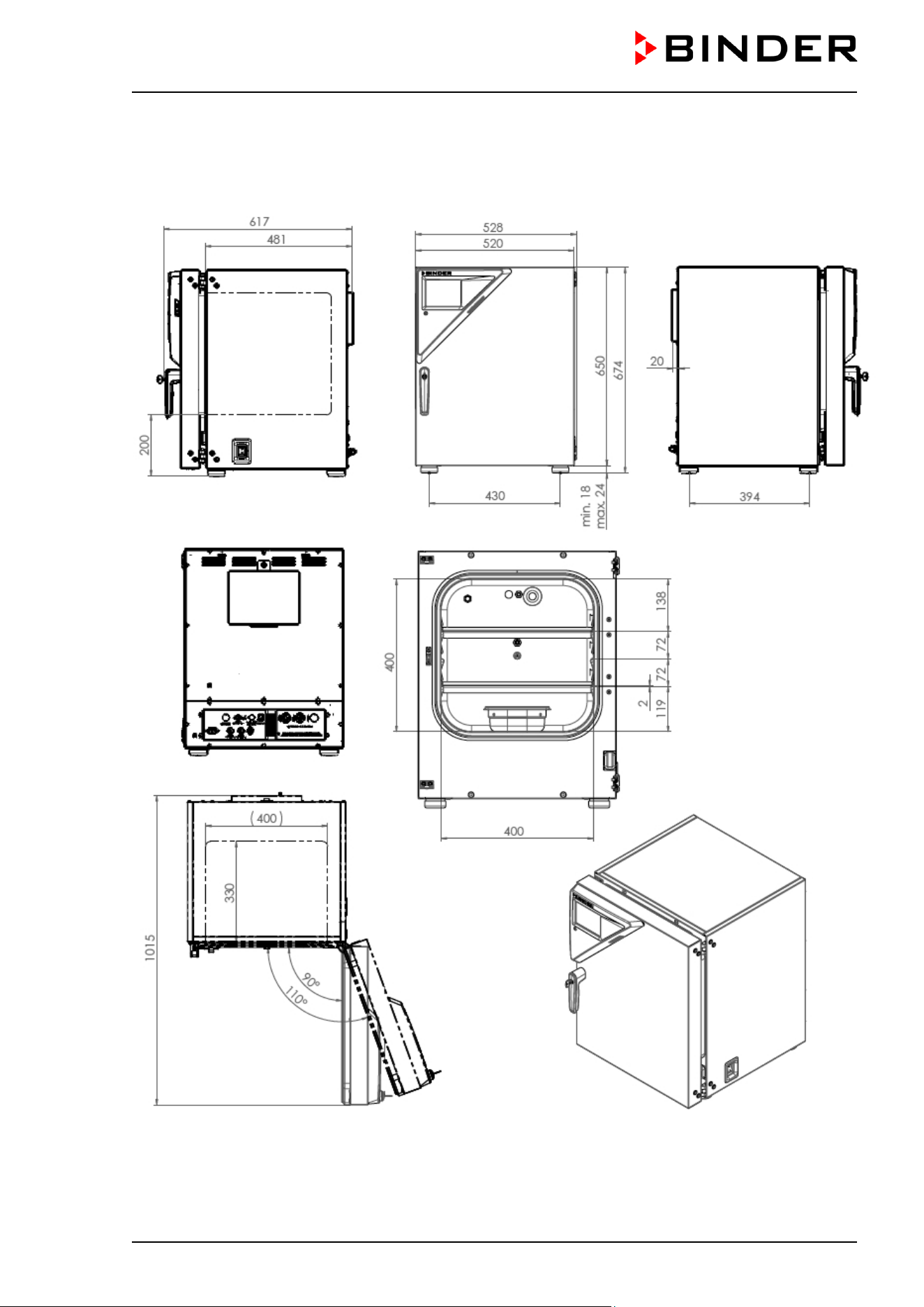
CB / CB-UL, CBF / CBF-UL (E7) 07/2022 Page 185/199
24.9 Dimensions
24.9.1 Chamber size 56
(Dimensions in mm)
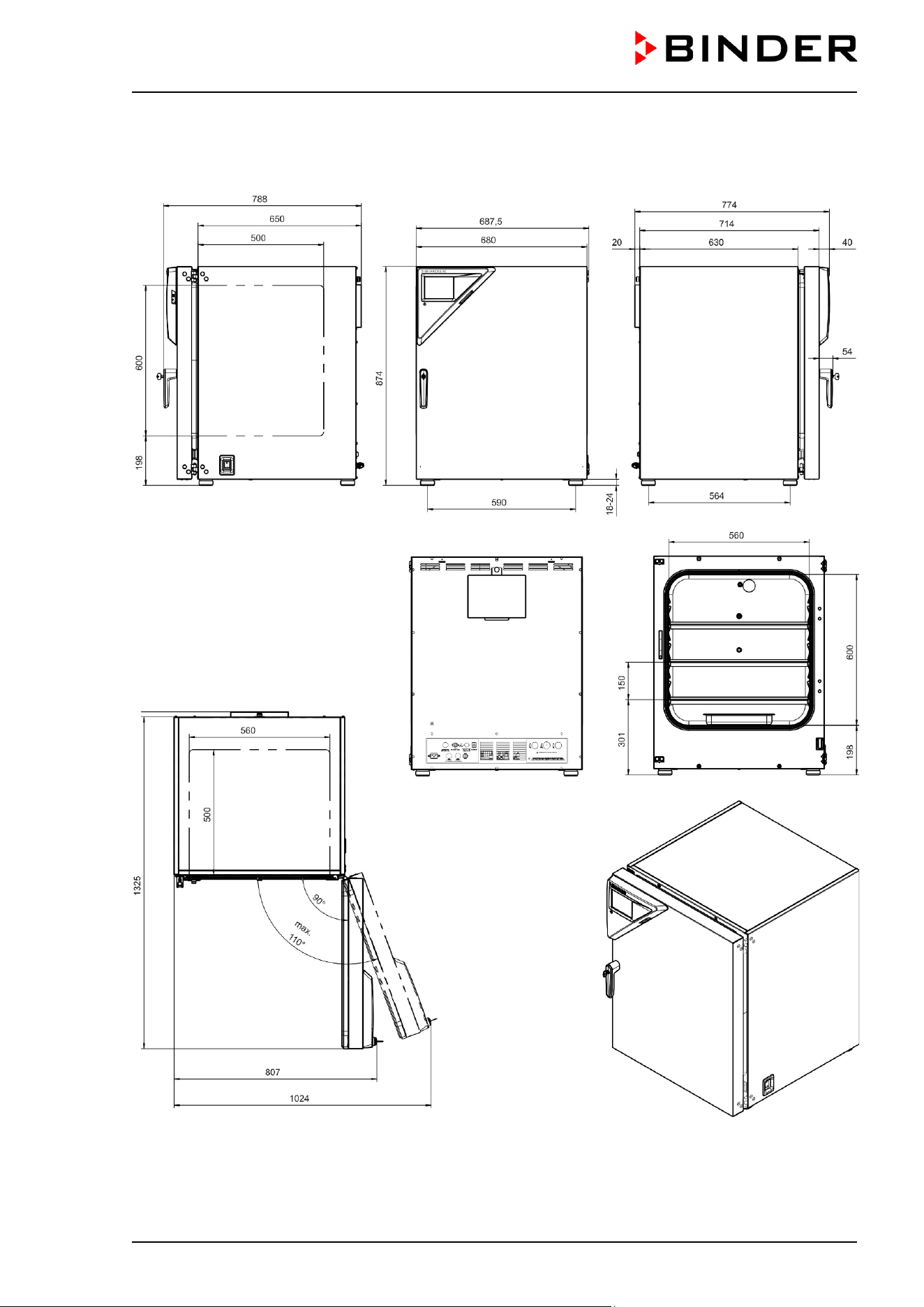
CB / CB-UL, CBF / CBF-UL (E7) 07/2022 Page 186/199
24.9.2 Chamber size 170
(Dimensions in mm)
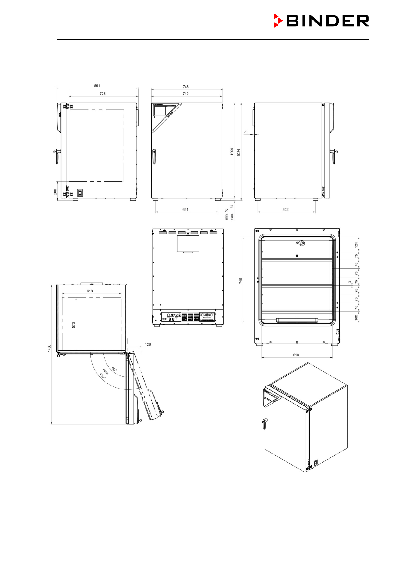
CB / CB-UL, CBF / CBF-UL (E7) 07/2022 Page 187/199
24.9.3 Chamber size 260
(Dimensions in mm)
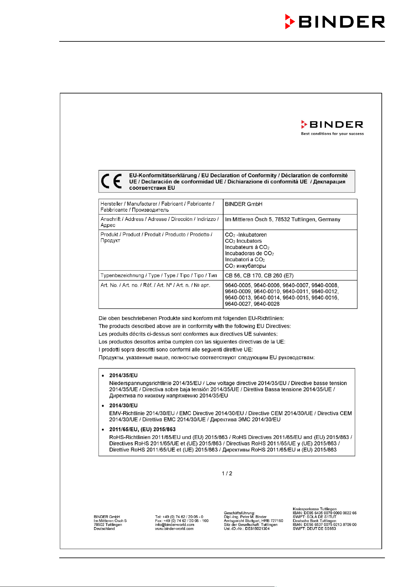
CB / CB-UL, CBF / CBF-UL (E7) 07/2022 Page 188/199
25. Certificates and declarations of conformity
25.1 EU Declaration of conformity for CB
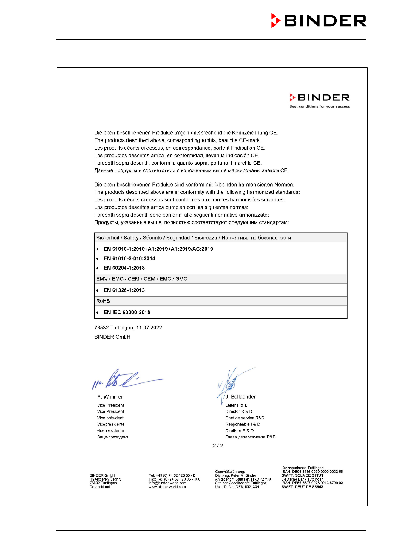
CB / CB-UL, CBF / CBF-UL (E7) 07/2022 Page 189/199
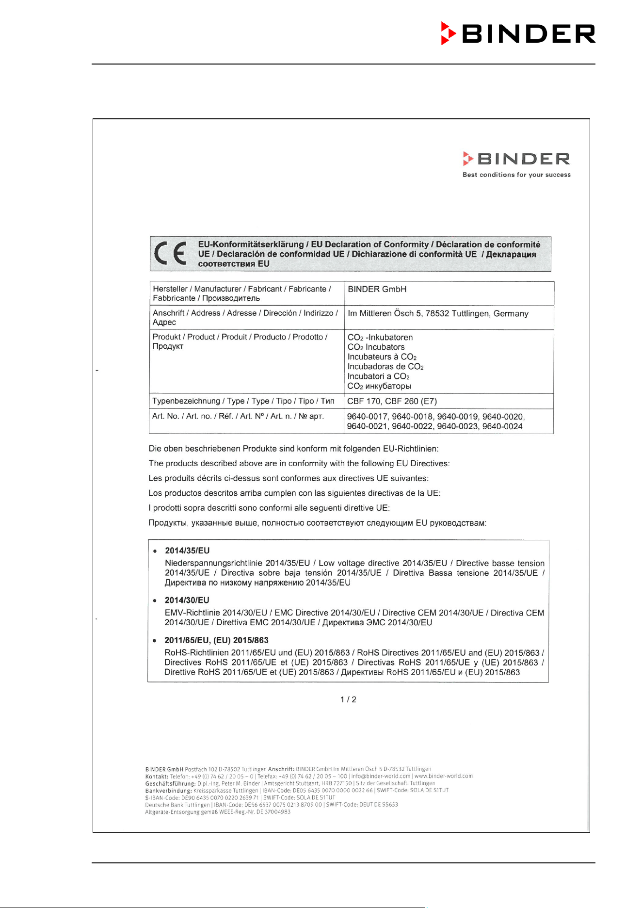
CB / CB-UL, CBF / CBF-UL (E7) 07/2022 Page 190/199
25.2 EU Declaration of conformity for CBF
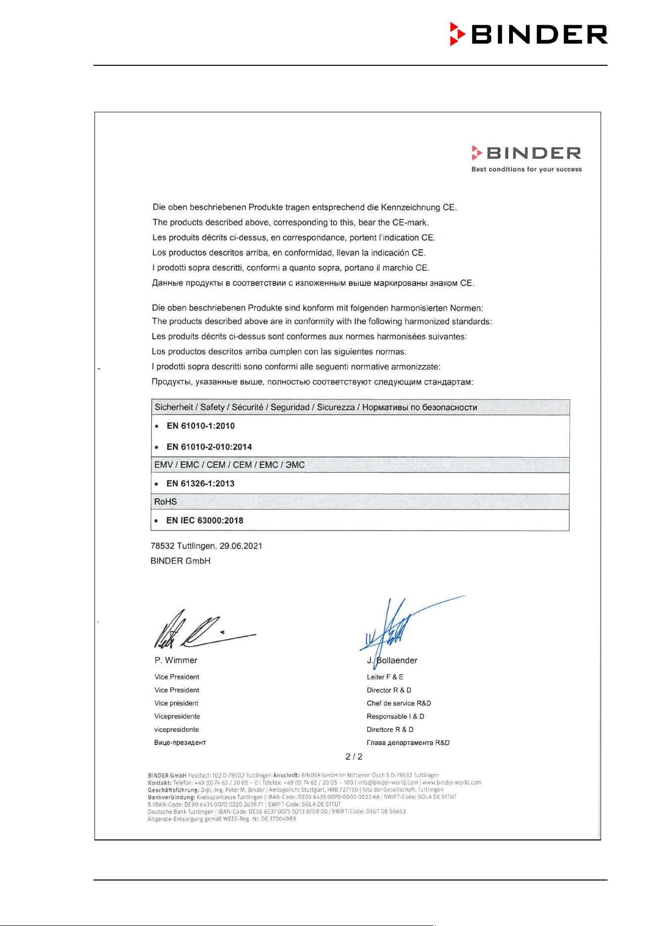
CB / CB-UL, CBF / CBF-UL (E7) 07/2022 Page 191/199
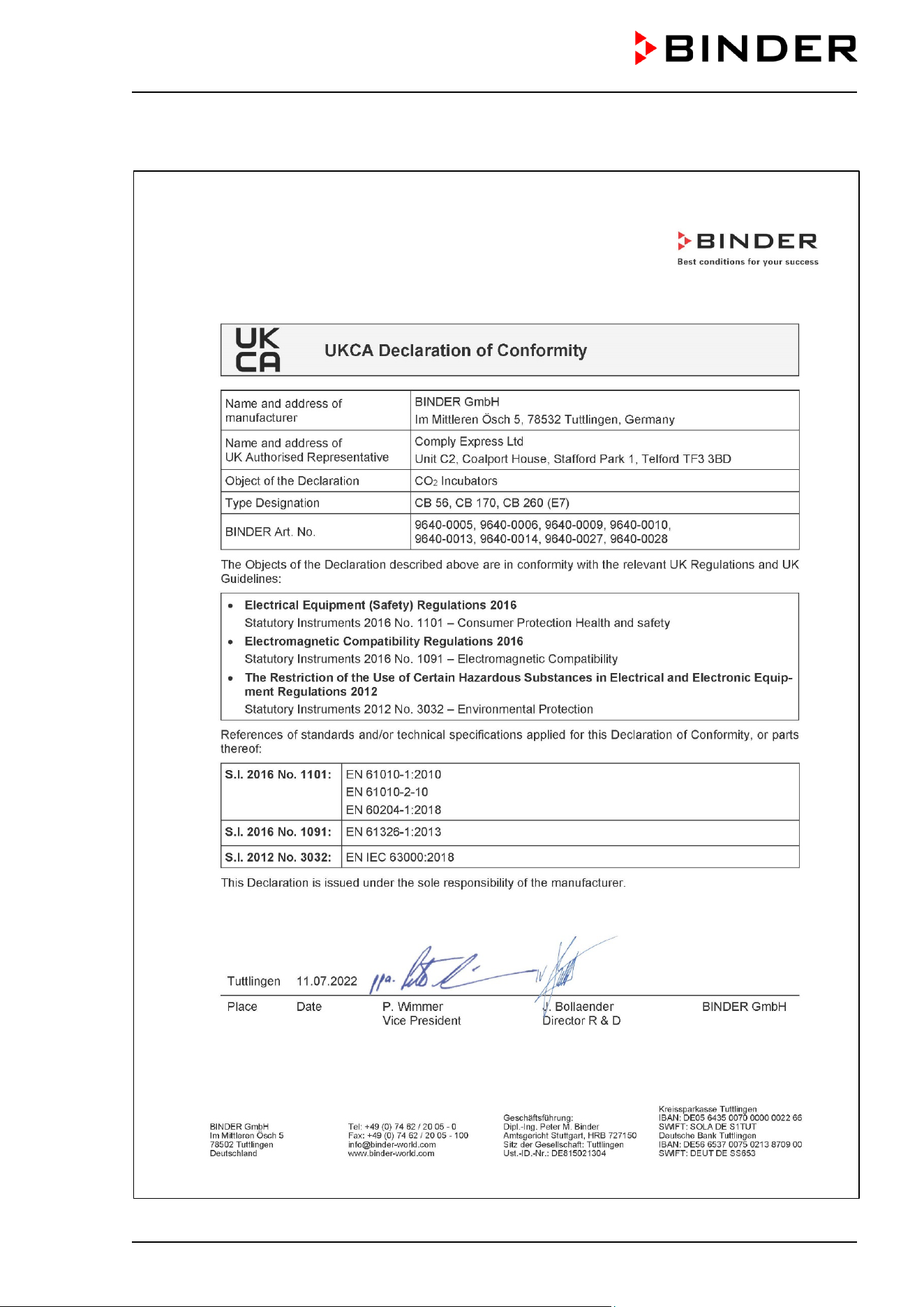
CB / CB-UL, CBF / CBF-UL (E7) 07/2022 Page 192/199
25.3 UKCA Declaration of Conformity for CB
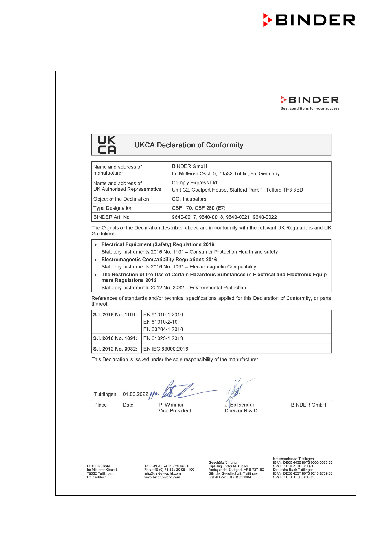
CB / CB-UL, CBF / CBF-UL (E7) 07/2022 Page 193/199
25.4 UKCA Declaration of Conformity for CBF
CB / CB-UL, CBF / CBF-UL (E7) 07/2022 Page 194/199
26. Contamination clearance certificate
26.1 For chambers located outside the USA and Canada
Declaration regarding safety and health
Erklärung zur Sicherheit and gesundheitlichen Unbedenklichkeit
The German Ordinance on Hazardous Substances (GefStofV), and the regulations regarding safety at the
workplace, require that this form be filled out for all products that are returned to us, so that the safety and
the health of our employees can be guaranteed.
Die Sicherheit und Gesundheit unserer Mitarbeiter, die Gefahrstoffverordnung GefStofV und die Vorschriften zur
Sicherheit am Arbeitsplatz machen es erforderlich, dass dieses Formblatt für alle Produkte, die an uns zurückgeschickt
wird.
Note: A repair is not possible without a completely filled out form.
Ohne Vorliegen des vollständig ausgefüllten Formblattes ist eine Reparatur nicht möglich.
• A completely filled out form must be transmitted via Fax (+49 (0) 7462 2005 93555) or by letter in
advance, so that this information is available before the equipment/component part arrives. A second
copy of this form must accompany the equipment/component part. In addition, the carrier should be
informed.
Eine vollständig ausgefüllte Kopie dieses Formblattes soll per Telefax (Nr. +49 (0) 7462 2005 93555) oder Brief
vorab an uns gesandt werden, so dass die Information vorliegt, bevor das Gerät/Bauteil eintrifft. Eine weitere Kopie
soll dem Gerät/Bauteil beigefügt sein. Ggf. ist auch die Spedition zu informieren.
• Incomplete information or non-conformity with this procedure will inevitably lead to substantial delays in
processing. Please understand the reason for this measure, which lies outside our area of influence and
will help us to speed up this procedure.
Unvollständige Angaben oder Nichteinhalten dieses Ablaufs führen zwangsläufig zu beträchtlichen Verzögerungen
in der Abwicklung. Bitte haben Sie Verständnis für Maßnahmen, die außerhalb unserer Einflussmöglichkeiten liegen
und helfen Sie mit, den Ablauf beschleunigen.
• Please print and fill out this form completely.
Bitte unbedingt vollständig ausfüllen!
1. Chamber/ component part / type: / Gerät / Bauteil / Typ:
2. Serial No./ Serien-Nr.:
3. Details about utilized substances / biological substances / Einzelheiten über die eingesetzten
Substanzen/biologische Materialien:
3.1 Designations / Bezeichnungen:
a) ____________________________________________________________________________
b) ____________________________________________________________________________
c) ____________________________________________________________________________
3.2 Safety measures required for handling these substances / Vorsichtsmaßnahmen beim Umgang
mit diesen Stoffen:
a) ____________________________________________________________________________
b) ____________________________________________________________________________
c) ____________________________________________________________________________
CB / CB-UL, CBF / CBF-UL (E7) 07/2022 Page 195/199
3.3 Measures to be taken in case of skin contact or release into the atmosphere / Maßnahmen
bei Personenkontakt oder Freisetzung:
a) ____________________________________________________________________________
b) ____________________________________________________________________________
c) ____________________________________________________________________________
d) ____________________________________________________________________________
3.4 Other important information that must be taken into account / Weitere zu beachtende und
wichtige Informationen:
a) ____________________________________________________________________________
b) ____________________________________________________________________________
c) ____________________________________________________________________________
4. Declaration on the risk of these substances (please checkmark the applicable items) /
Erklärung zur Gefährlichkeit der Stoffe (bitte Zutreffendes ankreuzen) :
4.1 For non-toxic, non-radioactive, biologically harmless materials / für nicht giftige, nicht
radioaktive, biologisch ungefährliche Stoffe:
We hereby guarantee that the above-mentioned chamber / component part… / Wir versichern, dass
o.g. Gerät/Bauteil...
Has not been exposed to or contains any toxic or otherwise hazardous substances /
weder giftige noch
sonstige gefährliche Stoffe enthält oder solche anhaften.
That eventually generated reaction products are non-toxic and also do not represent a hazard / auch
evtl. entstandene Reaktionsprodukte weder giftig sind noch sonst eine Gefährdung darstellen.
Eventual residues of hazardous substances have been removed /
evtl. Rückstände von Gefahrstoffen
entfernt wurden.
4.2 For toxic, radioactive, biologically harmful or hazardous substances, or any other
hazardous materials / für giftige, radioaktive, biologisch bedenkliche bzw. gefährliche Stoffe oder
anderweitig gefährliche Stoffe.
We hereby guarantee that … / Wir versichern, dass …
The hazardous substances, which have come into contact with the above-mentioned
equipment/component part, have been compl
etely listed under item 3.1 and that all information in this
regard is complete / die gefährlichen Stoffe, die mit dem o.g. Gerät/Bauteil in Kontakt kamen, in 3.1 aufgelistet
sind und alle Angaben vollständig sind.
That the chamber /component part has not been in contact with radioactivity / das Gerät/Bauteil nicht mit
Radioaktivität in Berührung kam
5. Kind of transport / transporter / Transportweg/Spediteur:
Transport by (means and name of transport company, etc.)
Versendung durch (Name Spediteur o.ä.)
___________________________________________________________________________________
Date of dispatch to BINDER GmbH /
Tag der Absendung an BINDER GmbH:
___________________________________________________________________________________
CB / CB-UL, CBF / CBF-UL (E7) 07/2022 Page 196/199
We hereby declare that the following measures have been taken / Wir erklären, dass folgende
Maßnahmen getroffen wurden:
Hazardous substances were removed from the chamber
including component parts, so that no hazard
exists for any person in the handling or repair of these items /
das Gerät/Bauteil wurde von Gefahrstoffen
befreit, so dass bei Handhabung/Reparaturen für die betreffenden Person keinerlei Gefährdung besteht
The chamber was securely packaged and properly identified /
das Gerät wurde sicher verpackt und
vollständig gekennzeichnet.
Information about the hazardousness of the shipment (if required) has been provided to the transporter
/
der Spediteur wurde (falls vorgeschrieben) über die Gefährlichkeit der Sendung informiert.
We hereby commit ourselves and guarantee that we will indemnify BINDER GmbH for all damages that
are a consequence of incomplete or incorrect information provided by us, and that we will exempt BINDER
GmbH from eventual damage claims by third parties./
Wir versichern, dass wir gegenüber BINDER für jeden
Schaden, der durch unvollständige und unrichtige Angaben
entsteht, haften und BINDER gegen eventuell
entstehende Schadenansprüche Dritter freistellen.
We are aware that, in accordance with Article 823 of the German Civil Code (BGB), we are directly liable
with regard to third parties, in this instance especial
ly the employees of BINDER GmbH, who have been
entrusted with the handling / repair of the chamber / component. /
Es ist uns bekannt, dass wir gegenüber
Dritten – hier insbesondere mit der Handhabung/Reparatur des Geräts/des Bauteils betraute Mitarbeiter d
er Firma
BINDER - gemäß §823 BGB direkt haften
Name: _______________________________________________________________________
Position/Title: _______________________________________________________________________
Date /
Datum: _______________________________________________________________________
Signature /
Unterschrift: _______________________________________________________________
Company stamp /
Firmenstempel:
Equipment that is returned to the factory for repair must be accompanied by a completely
filled out contamination clearance certificate. For service and maintenance on site, such a
contamination clearance certificate must be submitted to the service technician before the
start of any work. No repair or maintenance of the equipment is possible, without a properly
filled out contamination clearance certificate.
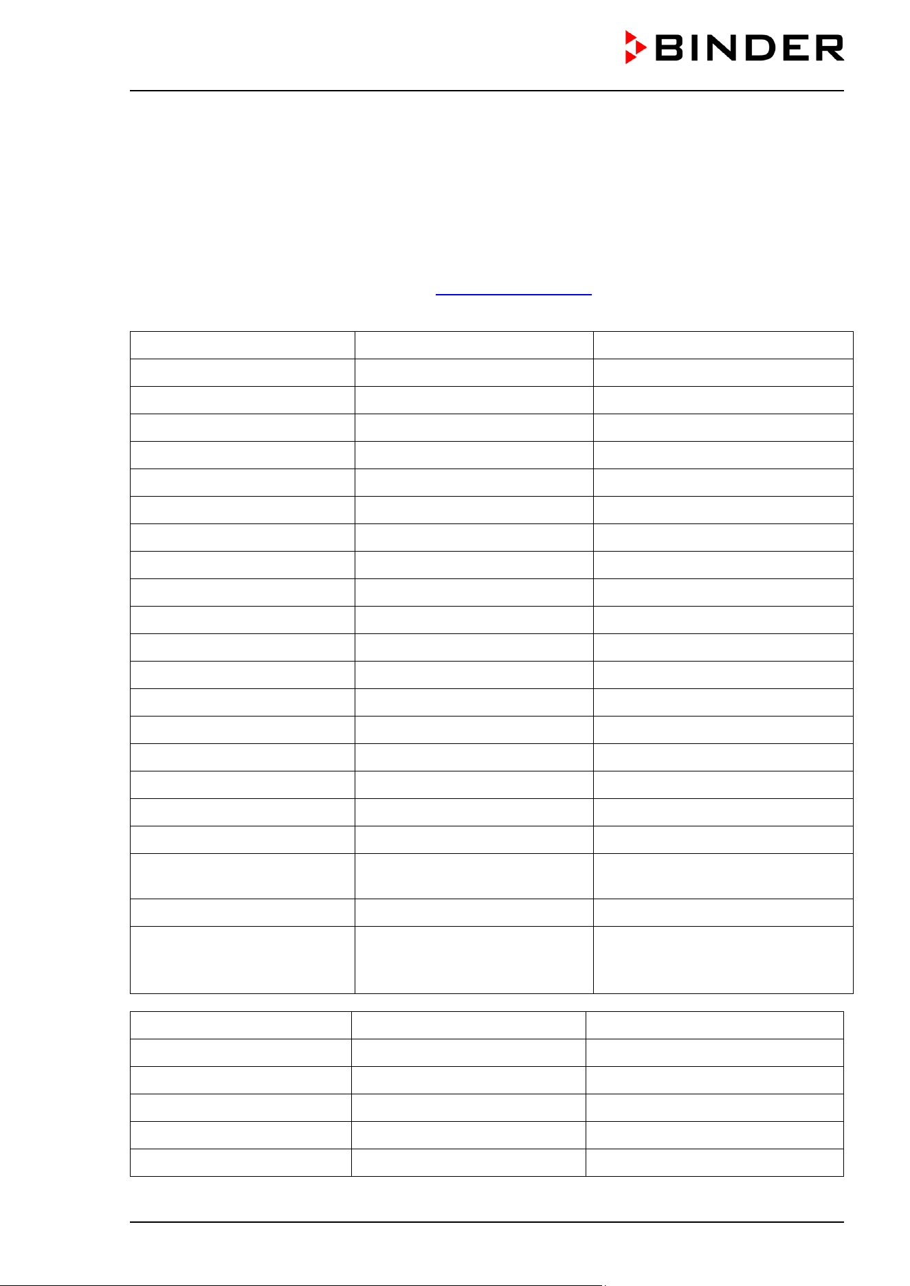
CB / CB-UL, CBF / CBF-UL (E7) 07/2022 Page 197/199
26.2 For chambers in the USA and Canada
Product Return Authorization Request
Please complete this form and the Customer Decontamination Declaration (next 2 pages) and attach the
required pictures. E-mail to: IDL_SalesOrderProcessing_USA@binder-world.com
After we have received and reviewed the complete information we will decide on the issue of a RMA
number. Please be aware that size specifications, voltage specifications as well as performance
specifications are available on the internet at
www.binder-world.us at any time.
Take notice of shipping laws and regulations.
Please fill:
Reason for return request Duplicate order
Duplicate shipment
Demo Page one completed by sales
Power Plug / Voltage 115V / 230 V / 208 V / 240V
Size does not fit space
Transport Damage Shock watch tripped? (pictures)
Other (specify below)
_____________________
Is there a replacement PO? Yes No
If yes -> PO #
If yes -> Date PO placed
Purchase order number
BINDER model number
BINDER serial number
Date chamber was received
Was the chamber unboxed? Yes No
Was the chamber plugged in? Yes No
Was the chamber in
operation?
Yes No
Pictures of chamber attached?
Pictures of Packaging
attached?
Yes No
Yes No
Pictures have to be attached!
Customer Contact Information Distributor Contact Information
Name
Company
Address
Phone
E-mail
CB / CB-UL, CBF / CBF-UL (E7) 07/2022 Page 198/199
Customer (End User) Decontamination Declaration
Health and Hazard Safety declaration
To protect the health of our employees and the safety at the workplace, we require that this form is
completed by the user for all products and parts that are returned to us. (Distributors or Service
Organizations cannot sign this form)
NO RMA number will be issued without a completed form. Products or parts returned to our
NY warehouse without a RMA number will be refused at the dock.
A second copy of the completed form must be attached to the outside of the shipping box.
1. Chamber/ component part / type:
2. Serial No.
3. List any exposure to hazardous liquids, gasses or substances and radioactive material
3.1 List with MSDS sheets attached where available or needed
(if there is not enough space available below, please attach a page):
a) ____________________________________________________________________________
b) ____________________________________________________________________________
c) ____________________________________________________________________________
3.2 Safety measures required for handling the list under 3.1
a) ____________________________________________________________________________
b) ____________________________________________________________________________
c) ____________________________________________________________________________
3.3 Measures to be taken in case of skin contact or release into the atmosphere:
a) ____________________________________________________________________________
b) ____________________________________________________________________________
c) ____________________________________________________________________________
d) ____________________________________________________________________________
3.4 Other important information that must be considered:
a) ____________________________________________________________________________
b) ____________________________________________________________________________
c) ____________________________________________________________________________
CB / CB-UL, CBF / CBF-UL (E7) 07/2022 Page 199/199
4. Declaration of Decontamination
For toxic, radioactive, biologically and chemically harmful or hazardous substances, or any other
hazardous materials.
We hereby guarantee that
4.1 Any hazardous substances, which have come into contact with the above-mentioned equipment /
component part, have been completely listed under item 3.1 and that all information in this regard is
complete.
4.2 That the chamber /component part has not been in contact with radioactivity
4.3 Any Hazardous substances were removed from the chamber / component part, so that no hazard
exists for a person in the shipping, handling or repair of these returned chamber
4.4 The chamber
was securely packaged in the original undamaged packaging and properly identified
on the outside of the packaging material with the chamber designation, the RMA number and a copy
of this declaration.
4.5 Shipping laws and regulations have not been violated.
I hereby commit and guarantee that we will indemnify BINDER Inc. for all damages that are a
consequence of incomplete or incorrect information provided by us, and that we will indemnify
and hold harmless BINDER Inc. from eventual damage claims by third parties.
Name: _______________________________________________________________________
Position: _______________________________________________________________________
Company: _______________________________________________________________________
Address: _______________________________________________________________________
Phone #: _______________________________________________________________________
Email: _______________________________________________________________________
Date: _______________________________________________________________________
Signature: ________________________________________________________________________
Equipment returned to the NY warehouse for repair must be accompanied by a completed
customer decontamination declaration. For service and maintenance works on site, such a
customer decontamination declaration must be submitted to the service technician before the
start of work. No repair or maintenance of the equipment is possible without a completed form.
