Loading ...
Loading ...
Loading ...

VDL (E3.1) 10/2020 Page 7/196
28.3 VDL / VDL-UL technical data .......................................................................................................... 177
28.4 Equipment and options (extract) ..................................................................................................... 179
28.5 Accessories and spare parts (extract) ............................................................................................ 180
28.6 Dimensions...................................................................................................................................... 182
28.6.1 VDL 23 .................................................................................................................................. 182
28.6.2 VDL 56 .................................................................................................................................. 183
28.6.3 VDL 115 ................................................................................................................................ 184
29. INDEX ................................................................................................................. 185
30. CERTIFICATES AND DECLARATIONS OF CONFORMITY ............................. 187
30.1 EU Declaration of Conformity.......................................................................................................... 187
31. PRODUCT REGISTRATION .............................................................................. 190
32. CONTAMINATION CLEARANCE CERTIFICATE ............................................. 191
32.1 For chambers located outside USA and Canada ........................................................................... 191
32.2 For chambers located in USA and Canada .................................................................................... 194
List of figures
Figure 1: Position of labels on the chamber (example) ............................................................................... 12
Figure 2: Type plate (example of VDL 115) ................................................................................................ 13
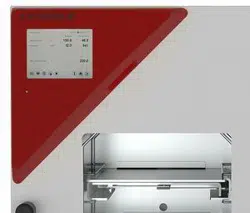
Figure 3: VDL 115 with MB2 controller ....................................................................................................... 41
Figure 4: Triangular instrument box (controller housing) with MB2 program controller and USB interface 42
Figure 5: Chamber rear (example: VDL 115) .............................................................................................. 42
Figure 6: Rear connection panel VDL with options ..................................................................................... 43
Figure 7: Area classification of the closed chamber (view without housing, insulation, heater and outer
chamber) ...................................................................................................................................... 45
Figure 8: Area classification in the surroundings of the chamber (schematic representation, standard
device) .......................................................................................................................................... 46
Figure 9: Area classification in the surroundings of the chamber during operation (example) ................... 47
Figure 10: Operating the expansion racks .................................................................................................. 53
Figure 11: Mounting the pressure regulator on the chamber rear .............................................................. 55
Figure 12: Compressed air connection on the pressure regulator .............................................................. 56
Figure 13: VDL mounted on pump module ................................................................................................. 57
Figure 14: Pump module, rear view (example size 115) ............................................................................ 57
Figure 15: Position of the Vacuum connection (6) on the chamber rear (example size 56) ....................... 59
Figure 16: Vacuum pump VP 4 (MZ2C EX) ................................................................................................ 61
Figure 17: Variable length of the tilt protection holder depending on the bend .......................................... 65
Figure 18: Possibilities of grounding (schematic representation) ............................................................... 66
Figure 19: Mounting the grounding cable on the VDL................................................................................. 67
Figure 20: Normal display of the MB2 program controller (sample values) ................................................ 74
Figure 21: Operating functions of the MB2 controller in normal display (example values) ......................... 75
Figure 22: Pressure regulator and sweeping plug for compressed air sweeping on the chamber rear ..... 86
Figure 23: analog pressure display (manometer) for compressed air sweeping on the chamber front ...... 86
Figure 22: Pressure regulator with defined setting at the upper stop ......................................................... 87
Figure 24: Schematic timing of the drying process and drying monitoring ............................................... 103
Figure 25: Pressure regulator and sweeping plug for compressed air sweeping on the chamber rear ... 160
Figure 26: Connection cable on the “Analog output” (3b) connection...................................................... 161
Figure 26: SUB-D socket for the analog outputs option ............................................................................ 161
Figure 29: Measuring connection (12) with measuring access port .......................................................... 162
Figure 29: Connection cable on the “Object temperature input” connection (3a) ..................................... 162
Figure 29: Plug connection between measuring access port and Lemo socket ....................................... 162
Figure 29: Cable connection of the optional Pt 100 sensor ...................................................................... 162
Loading ...
Loading ...
Loading ...
