Home
Bookmarks
Home
Binder
Binder VDL 115 User Manual
Page 190
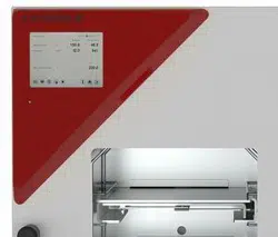
Binder VDL 115 -liter vacuum drying chamber for flammable solvents
User Manual - Page 190
For VDL 115.
PDF File Manual
,
197 pages
,
Read Online
|
Download pdf file
More photos
1. Safety
1.1 Personnel Qualification
1.2 Operating manual
1.3 Legal considerations
1.4 Structure of the safety instructions
1.4.1 Signal word panel
1.4.2 Safety alert symbol
1.4.3 Explosion protection symbol
1.4.4 Pictograms in this manual
1.4.5 Word message panel structure
1.5 Localization / position of safety labels on the chamber
1.6 Type plate
1.7 Safety instructions on installing and operating the vacuum drying oven
1.7.1 Safety instructions on installation and ambient conditions of the chamber
1.7.1.1 Aeration / ventilation of the installation site
1.7.1.2 No installation in potentially explosive areas of Zone 1 or 0
1.7.1.3 Equipotential bonding according to the grounding concept
1.7.1.4 Accessibility to the disconnection from the power grid
1.7.1.5 Technical ventilation (extraction)
1.7.2 Safety instructions on compressed air supply
1.7.3 Safety instructions on vacuum supply
1.7.3.1 Selection and location of a suitable pump
1.7.3.2 Observing the permissible gas inlet temperature
1.7.3.3 Technical Ventilation (extraction)
1.7.4 Safety instructions on the charging material
1.7.5 Safety instructions on operating the vacuum drying oven
1.8 Ex classification of the chamber and immediate surroundings
1.9 Intended use
1.10 Foreseeable Misuse
1.11 Residual Risks
2. Operator responsibility, documentation, and measures
2.1 Risk assessment / explosion protection document
2.2 Employee training and protocols
2.3 Operating instructions
2.4 Safety data sheets
2.5 Protective equipment
2.6 Standard Operating Procedures (SOPs)
2.7 Testing and maintenance
2.8 Operation log
3. Description of the equipment
3.1 Manufacturer's safety plan: Protective measures and equipment
3.2 Chamber overview
3.3 Triangular instrument box with MB2 controller
3.4 Connections on the rear of the chamber
3.5 Area classification, information for the zone classification
3.5.1 Area classification inside the chamber
3.5.2 Area classification in the surroundings of the chamber
3.5.3 Area classification in the surroundings of the chamber: extraction lead to the pump, location of the pump
4. Completeness of delivery, transportation, storage, and installation
4.1 Unpacking, and checking equipment and completeness of delivery
4.2 Guidelines for safe lifting and transportation
4.3 Storage
5. Location of installation and ambient conditions
5.1 General requirements for installation
5.2 Ventilation and extraction (technical ventilation)
5.2.1 Ventilation for heat removal in normal operation
5.2.2 Technical ventilation during chamber operation and when emptying the condensate catchpot of the pump
5.2.3 Air supply (breaking the vacuum) during operation with inert gas
5.3 Equipotential bonding
5.4 Ambient conditions
5.5 Compressed air supply for sweeping the area for electrical equipment, the preheating chamber, and the controller housing
5.6 Fire extinguisher
5.7 Lightning protection device
6. Installation and connections
6.1 Vacuum expansion racks and rack holders
6.2 Mounting the pressure regulator
6.3 Connecting compressed air supply for sweeping the area for electrical equipment, the preheating chamber, and the controller housing
6.4 Pump module (option)
6.4.1 Mounting
6.4.2 Achieving equipotential bonding acc. to the grounding plan
6.4.3 Connection of an extraction system at the pump module
6.5 Vacuum connection
6.5.1 Instructions for using vacuum pumps
6.5.2 Vacuum pump VP4 (option)
6.5.3 Installation of the vacuum pump VP4 in the pump module (option)
6.5.4 Note on the use of a flame arrester
6.5.5 ATEX connection kit for vacuum pump VP4 (option)
6.6 Connecting inert gas supply
6.7 Mounting the tilt protection holders
6.8 Achieving equipotential bonding / Grounding concept
6.9 Electrical connection
7. Explosion safety tests before commissioning
7.1 Scope of the functional test
7.2 Explosion protection plan
7.3 Objective of testing
7.4 Testing before initial commissioning
7.4.1 Scope of the test
7.4.1.1 Testing the plausibility of the explosion protection plan and measures
7.4.1.2 Verifying the implementation of measures
7.4.1.3 Checking the deadlines for the recurring tests
7.4.1.4 Verifying the maintenance plan
7.4.2 Tests of technical ventilation systems, gas warning devices, inerting devices, devices, protective systems or safety, control or regulating devices, and other technical devices for explosion protection
7.5 Inspection after changes requiring review
7.6 Recurring tests for the explosive safety of the system
8. Functional overview and menu structure of the controller
8.1 Operating functions in normal display
8.2 Display views: Normal display, program display, chart-recorder display
8.3 MB2 controller icons overview
8.4 MB2 controller operating modes
8.4.1 MB2 controller menu structure
8.4.2 Main menu
8.4.3 âSettingsâ submenu
8.4.4 âServiceâ submenu
8.5 Principle of controller entries
8.6 Performance during and after power failures
9. Start up and performing the drying process
9.1 Requirements for safe commissioning
9.2 Overview of the drying process
9.3 Sweeping the area for electrical equipment, the preheating chamber, and the controller housing (triangular instrument box) with compressed air
9.3.1 Setting the pressure regulator for sweeping with compressed air
9.3.2 Sweeping before starting up / restarting the chamber
9.3.3 Sweeping during chamber operation
9.3.4 Sweeping after completion of chamber operation (recommended):
9.4 Condition after establishing the power connection
9.5 Standby mode Turning on and off the vacuum drying oven
9.6 Controller settings upon start up
9.7 Loading
9.8 Evacuation
9.9 Breaking the vacuum (flooding)
9.9.1 Ventilation after completing the drying procedure (flooding with ambient air or inert gas)
9.9.2 Operation with inert gas
9.9.3 Ventilation / breaking the vacuum in case of a power failure
9.9.4 Ventilation before completing the drying procedure (flooding with ambient air or inert gas)
9.10 Unloading the loading material
9.11 Removing the full condensate catchpot of the pump
9.12 Preparing a new drying process
10. Set-point entry
10.1 Set-point entry through the âSetpointsâ menu
10.2 Direct setpoint entry via Normal display
11. Setting special controller functions
11.1 Menu structure
11.1.1 âFunctions on/offâ menu
11.1.2 âControl on/offâ menu
11.2 Using the optional universal connection âGAS/AIR 2â for ventilation
11.3 Close all valves
11.4 Activating / deactivating temperature control
11.5 Activating / deactivating pressure control
11.6 Drying monitoring
12. Authorization levels and password protection
12.1 User management, authorization levels and password protection
12.2 Log in
12.3 Log out
12.4 User change
12.5 Password assignment and password change
12.5.1 Password change
12.5.2 Deleting the password for an individual authorization level
12.5.3 New password assignment for âserviceâ or âadminâ authorization level when the password function was deactivated
12.6 Activation code
13. General controller settings and information
13.1 Selecting the controllerâs menu language
13.2 Setting date and time
13.3 Selecting the temperature unit
13.4 Display configuration
13.4.1 Adapting the display parameters
13.4.2 Touchscreen calibration
13.5 Event list
13.6 Service contact page
13.7 Current operating parameters
13.8 Technical chamber information
14. Temperature safety devices
14.1 Safety temperature limiter (TL) class 2
14.2 Overtemperature safety controller class 2
14.2.1 Safety controller mode
14.2.2 Setting the safety controller
14.2.3 Message and measures in the state of alarm
14.2.4 Function check
15. Tolerance range settings
15.1 Setting the alarm delay times and the tolerance ranges
15.1.1 Alarm condition
16. Notification and alarm functions
16.1 Information messages
16.2 Alarm messages
16.3 Resetting an alarm
16.4 Activating / deactivating the audible alarm (buzzer)
16.5 Test alarm of the safety temperature limiter (TL)
17. Timer program (stopwatch function)
17.1 Starting a timer program
17.1.1 Performance during program delay time
17.2 Stopping a running timer program
17.2.1 Pausing a running timer program
17.2.2 Cancelling a running timer program
17.3 Performance after the end of the program
18. Time programs
18.1 Starting an existing time program
18.1.1 Performance during program delay time
18.2 Stopping a running time program
18.2.1 Pausing a running time program
18.2.2 Cancelling a running time program
18.3 Performance after the end of the program
18.4 Creating a new time program
18.5 Program editor: program management
18.5.1 Deleting a time program
18.6 Section editor: section management
18.6.1 Add a new program section
18.6.2 Copy and insert or replace a program section
18.6.3 Deleting a program section
18.7 Value entry for a program section
18.7.1 Section duration
18.7.2 Set-point ramp and set-point step
18.7.3 Special controller functions
18.7.4 Setpoint entry
18.7.5 Tolerance range
18.7.6 Repeating one or several sections within a time program
18.7.7 Saving the time program
19. Week programs
19.1 Starting an existing week program
19.2 Cancelling a running week program
19.3 Creating a new week program
19.4 Program editor: program management
19.4.1 Deleting a week program
19.5 Section editor: section management
19.5.1 Add a new program section
19.5.2 Copy and insert or replace a program section
19.5.3 Deleting a program section
19.6 Value entry for a program section in the Section view
19.6.1 Set-point ramp and set-point step modes
19.6.2 Weekday
19.6.3 Start time
19.6.4 Setpoint entry
19.6.5 Special controller functions
20. Network and communication
20.1 Ethernet
20.1.1 Configuration
20.1.2 Display of MAC address
20.2 Web server
20.3 E-Mail
21. USB menu: Data transfer via USB interface
21.1 Using the USB connection during chamber operation
22. Chart recorder display
22.1 Views
22.1.1 Show and hide legend
22.1.2 History display
22.2 Setting the parameters
23. Reference measurements
23.1 Checking the temperature in the inner chamber
23.1.1 Checking the controller display
23.1.2 Checking the spatial temperature exactitude
23.1.3 Checking the function of the manometer for compressed air sweeping
24. Options
24.1 APT-COM⢠4 Multi Management software (option)
24.2 Analog outputs for temperature and pressure (option)
24.3 Object temperature display with flexible Pt 100 temperature sensor (option)
24.3.1 Connection of the object temperature sensor
24.3.2 Display on the MB2 controller
25. Cleaning and decontamination
25.1 Safety instructions on cleaning and decontamination
25.2 Cleaning
25.3 Decontamination / chemical disinfection
26. Maintenance and service, troubleshooting, repair, testing
26.1 General information, personnel qualifications
26.2 Simple troubleshooting
26.3 Maintenance, Service
26.3.1 Safety instructions on maintenance work
26.3.2 Maintenance intervals
26.4 Service Reminder
26.4.1 BINDER Service contact data
26.5 Sending the chamber back to BINDER GmbH
27. Disposal
27.1 Disposal of the transport packing
27.2 Decommissioning
27.3 Disposal of the chamber in the Federal Republic of Germany
27.4 Disposal of the chamber in the member states of the EU except for the Federal Republic of Germany
27.5 Disposal of the chamber in non-member states of the EU
28. Technical description
28.1 Factory calibration and adjustment
28.2 Over current protection
28.3 VDL / VDL-UL technical data
28.4 Equipment and options (extract)
28.5 Accessories and spare parts (extract)
28.6 Dimensions
28.6.1 VDL 23
28.6.2 VDL 56
28.6.3 VDL 115
29. Index
30. Certificates and declarations of conformity
30.1 EU Declaration of Conformity
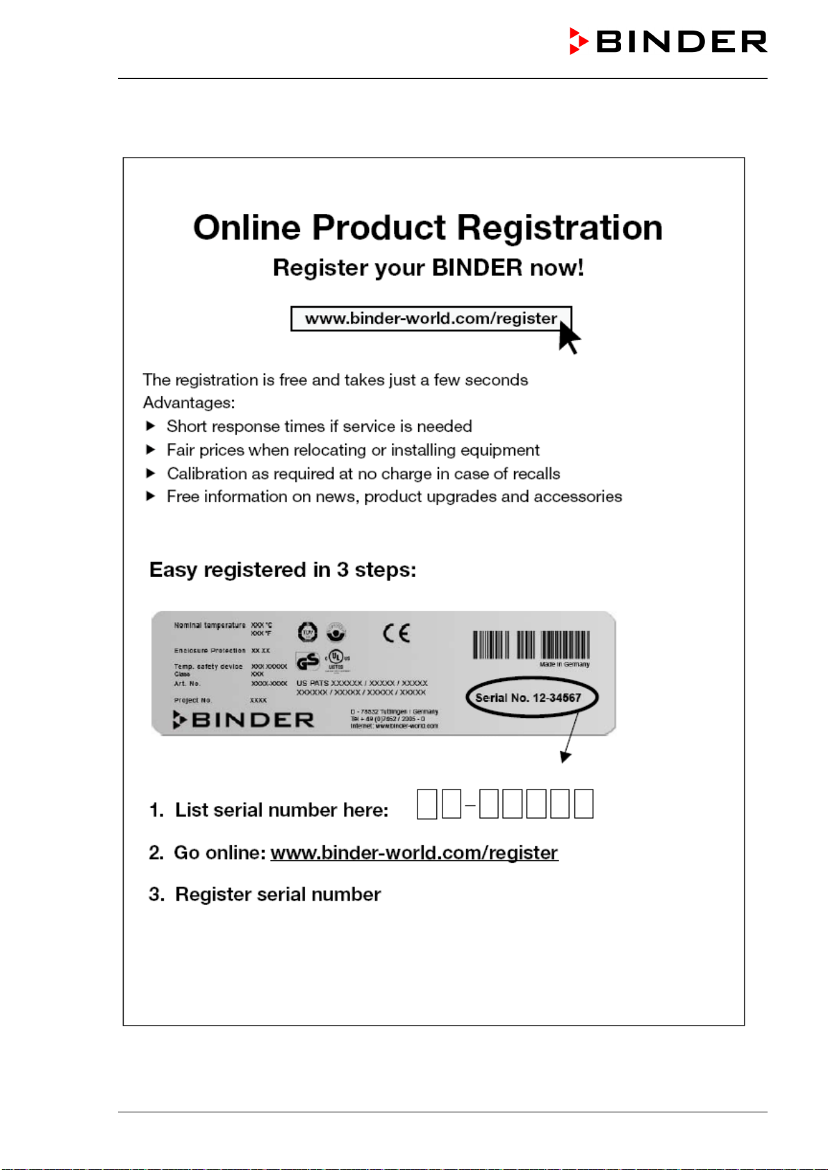
31. Product registration
32. Contamination clearance certificate
32.1 For chambers located outside USA and Canada
32.2 For chambers located in USA and Canada
Leere Seite
Page 190/197
Page 1
Page 2
Page 3
Page 4
Page 5
Page 6
Page 7
Page 8
Page 9
Page 10
Page 11
Page 12
Page 13
Page 14
Page 15
Page 16
Page 17
Page 18
Page 19
Page 20
Page 21
Page 22
Page 23
Page 24
Page 25
Page 26
Page 27
Page 28
Page 29
Page 30
Page 31
Page 32
Page 33
Page 34
Page 35
Page 36
Page 37
Page 38
Page 39
Page 40
Page 41
Page 42
Page 43
Page 44
Page 45
Page 46
Page 47
Page 48
Page 49
Page 50
Page 51
Page 52
Page 53
Page 54
Page 55
Page 56
Page 57
Page 58
Page 59
Page 60
Page 61
Page 62
Page 63
Page 64
Page 65
Page 66
Page 67
Page 68
Page 69
Page 70
Page 71
Page 72
Page 73
Page 74
Page 75
Page 76
Page 77
Page 78
Page 79
Page 80
Page 81
Page 82
Page 83
Page 84
Page 85
Page 86
Page 87
Page 88
Page 89
Page 90
Page 91
Page 92
Page 93
Page 94
Page 95
Page 96
Page 97
Page 98
Page 99
Page 100
Page 101
Page 102
Page 103
Page 104
Page 105
Page 106
Page 107
Page 108
Page 109
Page 110
Page 111
Page 112
Page 113
Page 114
Page 115
Page 116
Page 117
Page 118
Page 119
Page 120
Page 121
Page 122
Page 123
Page 124
Page 125
Page 126
Page 127
Page 128
Page 129
Page 130
Page 131
Page 132
Page 133
Page 134
Page 135
Page 136
Page 137
Page 138
Page 139
Page 140
Page 141
Page 142
Page 143
Page 144
Page 145
Page 146
Page 147
Page 148
Page 149
Page 150
Page 151
Page 152
Page 153
Page 154
Page 155
Page 156
Page 157
Page 158
Page 159
Page 160
Page 161
Page 162
Page 163
Page 164
Page 165
Page 166
Page 167
Page 168
Page 169
Page 170
Page 171
Page 172
Page 173
Page 174
Page 175
Page 176
Page 177
Page 178
Page 179
Page 180
Page 181
Page 182
Page 183
Page 184
Page 185
Page 186
Page 187
Page 188
Page 189
Page 190
Page 191
Page 192
Page 193
Page 194
Page 195
Page 196
Page 197
Contents
Table of Contents
Search
Previous
Next
Troubleshooting
Bookmarks
Loading ...
Loading ...
Loading ...
VDL (E3.1)
10/20
20
Page 190
/
1
96
31.
Produ
ct
re
gistration
Loading ...
Loading ...
Loading ...
File type: PDF
File name: 43003675_vdl-115.pdf
File size: 11.02 MB
File Language: English
Pages: 197
Author: Binder
File created: 2020-10-16
Published: 2021-08-19
Updated: 2023-05-22
Download File
Table of Contents
×
1. Safety
8
1.1 Personnel Qualification
8
1.2 Operating manual
8
1.3 Legal considerations
9
1.4 Structure of the safety instructions
10
1.4.1 Signal word panel
10
1.4.2 Safety alert symbol
10
1.4.3 Explosion protection symbol
10
1.4.4 Pictograms in this manual
11
1.4.5 Word message panel structure
12
1.5 Localization / position of safety labels on the chamber
12
1.6 Type plate
13
1.7 Safety instructions on installing and operating the vacuum drying oven
14
1.7.1 Safety instructions on installation and ambient conditions of the chamber
14
1.7.1.1 Aeration / ventilation of the installation site
15
1.7.1.2 No installation in potentially explosive areas of Zone 1 or 0
15
1.7.1.3 Equipotential bonding according to the grounding concept
15
1.7.1.4 Accessibility to the disconnection from the power grid
16
1.7.1.5 Technical ventilation (extraction)
16
1.7.2 Safety instructions on compressed air supply
16
1.7.3 Safety instructions on vacuum supply
17
1.7.3.1 Selection and location of a suitable pump
17
1.7.3.2 Observing the permissible gas inlet temperature
18
1.7.3.3 Technical Ventilation (extraction)
18
1.7.4 Safety instructions on the charging material
19
1.7.5 Safety instructions on operating the vacuum drying oven
20
1.8 Ex classification of the chamber and immediate surroundings
23
1.9 Intended use
25
1.10 Foreseeable Misuse
28
1.11 Residual Risks
30
2. Operator responsibility, documentation, and measures
32
2.1 Risk assessment / explosion protection document
32
2.2 Employee training and protocols
32
2.3 Operating instructions
33
2.4 Safety data sheets
33
2.5 Protective equipment
33
2.6 Standard Operating Procedures (SOPs)
34
2.7 Testing and maintenance
35
2.8 Operation log
35
3. Description of the equipment
36
3.1 Manufacturer's safety plan: Protective measures and equipment
37
3.2 Chamber overview
41
3.3 Triangular instrument box with MB2 controller
42
3.4 Connections on the rear of the chamber
42
3.5 Area classification, information for the zone classification
44
3.5.1 Area classification inside the chamber
45
3.5.2 Area classification in the surroundings of the chamber
46
3.5.3 Area classification in the surroundings of the chamber: extraction lead to the pump, location of the pump
47
4. Completeness of delivery, transportation, storage, and installation
48
4.1 Unpacking, and checking equipment and completeness of delivery
48
4.2 Guidelines for safe lifting and transportation
49
4.3 Storage
49
5. Location of installation and ambient conditions
49
5.1 General requirements for installation
49
5.2 Ventilation and extraction (technical ventilation)
51
5.2.1 Ventilation for heat removal in normal operation
51
5.2.2 Technical ventilation during chamber operation and when emptying the condensate catchpot of the pump
51
5.2.3 Air supply (breaking the vacuum) during operation with inert gas
51
5.3 Equipotential bonding
52
5.4 Ambient conditions
52
5.5 Compressed air supply for sweeping the area for electrical equipment, the preheating chamber, and the controller housing
52
5.6 Fire extinguisher
52
5.7 Lightning protection device
52
6. Installation and connections
53
6.1 Vacuum expansion racks and rack holders
53
6.2 Mounting the pressure regulator
54
6.3 Connecting compressed air supply for sweeping the area for electrical equipment, the preheating chamber, and the controller housing
56
6.4 Pump module (option)
57
6.4.1 Mounting
58
6.4.2 Achieving equipotential bonding acc. to the grounding plan
58
6.4.3 Connection of an extraction system at the pump module
59
6.5 Vacuum connection
59
6.5.1 Instructions for using vacuum pumps
59
6.5.2 Vacuum pump VP4 (option)
61
6.5.3 Installation of the vacuum pump VP4 in the pump module (option)
62
6.5.4 Note on the use of a flame arrester
64
6.5.5 ATEX connection kit for vacuum pump VP4 (option)
64
6.6 Connecting inert gas supply
64
6.7 Mounting the tilt protection holders
65
6.8 Achieving equipotential bonding / Grounding concept
66
6.9 Electrical connection
68
7. Explosion safety tests before commissioning
70
7.1 Scope of the functional test
70
7.2 Explosion protection plan
70
7.3 Objective of testing
71
7.4 Testing before initial commissioning
71
7.4.1 Scope of the test
71
7.4.1.1 Testing the plausibility of the explosion protection plan and measures
71
7.4.1.2 Verifying the implementation of measures
71
7.4.1.3 Checking the deadlines for the recurring tests
72
7.4.1.4 Verifying the maintenance plan
72
7.4.2 Tests of technical ventilation systems, gas warning devices, inerting devices, devices, protective systems or safety, control or regulating devices, and other technical devices for explosion protection
73
7.5 Inspection after changes requiring review
73
7.6 Recurring tests for the explosive safety of the system
73
8. Functional overview and menu structure of the controller
74
8.1 Operating functions in normal display
75
8.2 Display views: Normal display, program display, chart-recorder display
76
8.3 MB2 controller icons overview
77
8.4 MB2 controller operating modes
79
8.4.1 MB2 controller menu structure
79
8.4.2 Main menu
80
8.4.3 âSettingsâ submenu
81
8.4.4 âServiceâ submenu
81
8.5 Principle of controller entries
82
8.6 Performance during and after power failures
82
9. Start up and performing the drying process
83
9.1 Requirements for safe commissioning
83
9.2 Overview of the drying process
84
9.3 Sweeping the area for electrical equipment, the preheating chamber, and the controller housing (triangular instrument box) with compressed air
86
9.3.1 Setting the pressure regulator for sweeping with compressed air
86
9.3.2 Sweeping before starting up / restarting the chamber
87
9.3.3 Sweeping during chamber operation
87
9.3.4 Sweeping after completion of chamber operation (recommended):
88
9.4 Condition after establishing the power connection
88
9.5 Standby mode Turning on and off the vacuum drying oven
89
9.6 Controller settings upon start up
90
9.7 Loading
91
9.8 Evacuation
93
9.9 Breaking the vacuum (flooding)
93
9.9.1 Ventilation after completing the drying procedure (flooding with ambient air or inert gas)
93
9.9.2 Operation with inert gas
93
9.9.3 Ventilation / breaking the vacuum in case of a power failure
94
9.9.4 Ventilation before completing the drying procedure (flooding with ambient air or inert gas)
94
9.10 Unloading the loading material
95
9.11 Removing the full condensate catchpot of the pump
96
9.12 Preparing a new drying process
96
10. Set-point entry
97
10.1 Set-point entry through the âSetpointsâ menu
97
10.2 Direct setpoint entry via Normal display
98
11. Setting special controller functions
99
11.1 Menu structure
99
11.1.1 âFunctions on/offâ menu
99
11.1.2 âControl on/offâ menu
100
11.2 Using the optional universal connection âGAS/AIR 2â for ventilation
100
11.3 Close all valves
101
11.4 Activating / deactivating temperature control
101
11.5 Activating / deactivating pressure control
102
11.6 Drying monitoring
103
12. Authorization levels and password protection
105
12.1 User management, authorization levels and password protection
105
12.2 Log in
107
12.3 Log out
108
12.4 User change
109
12.5 Password assignment and password change
109
12.5.1 Password change
109
12.5.2 Deleting the password for an individual authorization level
111
12.5.3 New password assignment for âserviceâ or âadminâ authorization level when the password function was deactivated
112
12.6 Activation code
113
13. General controller settings and information
114
13.1 Selecting the controllerâs menu language
114
13.2 Setting date and time
114
13.3 Selecting the temperature unit
116
13.4 Display configuration
116
13.4.1 Adapting the display parameters
116
13.4.2 Touchscreen calibration
117
13.5 Event list
118
13.6 Service contact page
118
13.7 Current operating parameters
119
13.8 Technical chamber information
119
14. Temperature safety devices
120
14.1 Safety temperature limiter (TL) class 2
120
14.2 Overtemperature safety controller class 2
120
14.2.1 Safety controller mode
120
14.2.2 Setting the safety controller
121
14.2.3 Message and measures in the state of alarm
122
14.2.4 Function check
122
15. Tolerance range settings
122
15.1 Setting the alarm delay times and the tolerance ranges
122
15.1.1 Alarm condition
123
16. Notification and alarm functions
123
16.1 Information messages
123
16.2 Alarm messages
125
16.3 Resetting an alarm
126
16.4 Activating / deactivating the audible alarm (buzzer)
126
16.5 Test alarm of the safety temperature limiter (TL)
127
17. Timer program (stopwatch function)
129
17.1 Starting a timer program
129
17.1.1 Performance during program delay time
130
17.2 Stopping a running timer program
130
17.2.1 Pausing a running timer program
130
17.2.2 Cancelling a running timer program
130
17.3 Performance after the end of the program
130
18. Time programs
131
18.1 Starting an existing time program
131
18.1.1 Performance during program delay time
132
18.2 Stopping a running time program
132
18.2.1 Pausing a running time program
132
18.2.2 Cancelling a running time program
132
18.3 Performance after the end of the program
132
18.4 Creating a new time program
133
18.5 Program editor: program management
133
18.5.1 Deleting a time program
134
18.6 Section editor: section management
135
18.6.1 Add a new program section
136
18.6.2 Copy and insert or replace a program section
136
18.6.3 Deleting a program section
137
18.7 Value entry for a program section
138
18.7.1 Section duration
138
18.7.2 Set-point ramp and set-point step
139
18.7.3 Special controller functions
140
18.7.4 Setpoint entry
141
18.7.5 Tolerance range
141
18.7.6 Repeating one or several sections within a time program
142
18.7.7 Saving the time program
143
19. Week programs
143
19.1 Starting an existing week program
144
19.2 Cancelling a running week program
144
19.3 Creating a new week program
145
19.4 Program editor: program management
146
19.4.1 Deleting a week program
147
19.5 Section editor: section management
147
19.5.1 Add a new program section
148
19.5.2 Copy and insert or replace a program section
149
19.5.3 Deleting a program section
149
19.6 Value entry for a program section in the Section view
149
19.6.1 Set-point ramp and set-point step modes
150
19.6.2 Weekday
150
19.6.3 Start time
150
19.6.4 Setpoint entry
151
19.6.5 Special controller functions
151
20. Network and communication
152
20.1 Ethernet
152
20.1.1 Configuration
152
20.1.2 Display of MAC address
153
20.2 Web server
153
20.3 E-Mail
154
21. USB menu: Data transfer via USB interface
155
21.1 Using the USB connection during chamber operation
155
22. Chart recorder display
156
22.1 Views
156
22.1.1 Show and hide legend
156
22.1.2 History display
156
22.2 Setting the parameters
158
23. Reference measurements
159
23.1 Checking the temperature in the inner chamber
159
23.1.1 Checking the controller display
159
23.1.2 Checking the spatial temperature exactitude
159
23.1.3 Checking the function of the manometer for compressed air sweeping
160
24. Options
161
24.1 APT-COM⢠4 Multi Management software (option)
161
24.2 Analog outputs for temperature and pressure (option)
161
24.3 Object temperature display with flexible Pt 100 temperature sensor (option)
162
24.3.1 Connection of the object temperature sensor
162
24.3.2 Display on the MB2 controller
163
25. Cleaning and decontamination
163
25.1 Safety instructions on cleaning and decontamination
163
25.2 Cleaning
164
25.3 Decontamination / chemical disinfection
165
26. Maintenance and service, troubleshooting, repair, testing
167
26.1 General information, personnel qualifications
167
26.2 Simple troubleshooting
168
26.3 Maintenance, Service
171
26.3.1 Safety instructions on maintenance work
171
26.3.2 Maintenance intervals
172
26.4 Service Reminder
172
26.4.1 BINDER Service contact data
172
26.5 Sending the chamber back to BINDER GmbH
173
27. Disposal
173
27.1 Disposal of the transport packing
173
27.2 Decommissioning
173
27.3 Disposal of the chamber in the Federal Republic of Germany
174
27.4 Disposal of the chamber in the member states of the EU except for the Federal Republic of Germany
175
27.5 Disposal of the chamber in non-member states of the EU
176
28. Technical description
176
28.1 Factory calibration and adjustment
176
28.2 Over current protection
177
28.3 VDL / VDL-UL technical data
177
28.4 Equipment and options (extract)
179
28.5 Accessories and spare parts (extract)
180
28.6 Dimensions
182
28.6.1 VDL 23
182
28.6.2 VDL 56
183
28.6.3 VDL 115
184
29. Index
185
30. Certificates and declarations of conformity
187
30.1 EU Declaration of Conformity
187
31. Product registration
190
32. Contamination clearance certificate
191
32.1 For chambers located outside USA and Canada
191
32.2 For chambers located in USA and Canada
194
Leere Seite
197
Search:
×
Search