Issue 10/2020 Art. No. 7001-0384
Operating Manual
Translation of the original operating manual
VDL (E3.1)
Vacuum Drying Oven
with microprocessor program controller MB2
Model Model version Art. No.
VDL 23 VDL023-230V 9630-0009
VDL 23-UL VDL023UL-120V 9630-0013
VDL 56 VDL053-230V 9630-0010
VDL 56-UL VDL053UL-120V 9630-0014
VDL 115 VDL115-230V 9630-0011
VDL 115-UL VDL115UL-120V 9630-0015
BINDER GmbH
Address: Post office box 102, 78502 Tuttlingen, Germany Phone: +49 7462 2005 0
Fax: +49 7462 2005 100 Internet: http://www.binder-world.com
E-mail: info@binder-world.com Service Hotline: +49 7462 2005 555
Service Fax: +49 7462 2005 93 555 Service E-Mail: customerservice@binder-world.com
Service Hotline USA: +1 866 885 9794 or +1 631 224 4340 x3
Service Hotline Asia Pacific: +852 390 705 04 or +852 390 705 03
Service Hotline Russia and CIS: +7 495 988 15 16

VDL (E3.1) 10/2020 Page 2/196
Contents
1. SAFETY .................................................................................................................. 8
1.1 Personnel Qualification ....................................................................................................................... 8
1.2 Operating manual ................................................................................................................................ 8
1.3 Legal considerations ........................................................................................................................... 9
1.4 Structure of the safety instructions .................................................................................................... 10
1.4.1 Signal word panel ................................................................................................................... 10
1.4.2 Safety alert symbol ................................................................................................................. 10
1.4.3 Explosion protection symbol ................................................................................................... 10
1.4.4 Pictograms in this manual ....................................................................................................... 11
1.4.5 Word message panel structure ............................................................................................... 12
1.5 Localization / position of safety labels on the chamber .................................................................... 12
1.6 Type plate.......................................................................................................................................... 13
1.7 Safety instructions on installing and operating the vacuum drying oven .......................................... 14
1.7.1 Safety instructions on installation and ambient conditions of the chamber ............................ 14
1.7.1.1 Aeration / ventilation of the installation site ....................................................................... 15
1.7.1.2 No installation in potentially explosive areas of Zone 1 or 0 ............................................. 15
1.7.1.3 Equipotential bonding according to the grounding concept............................................... 15
1.7.1.4 Accessibility to the disconnection from the power grid ...................................................... 16
1.7.1.5 Technical ventilation (extraction) ....................................................................................... 16
1.7.2 Safety instructions on compressed air supply ........................................................................ 16
1.7.3 Safety instructions on vacuum supply .................................................................................... 17
1.7.3.1 Selection and location of a suitable pump ......................................................................... 17
1.7.3.2 Observing the permissible gas inlet temperature .............................................................. 18
1.7.3.3 Technical Ventilation (extraction) ...................................................................................... 18
1.7.4 Safety instructions on the charging material ........................................................................... 19
1.7.5 Safety instructions on operating the vacuum drying oven ...................................................... 20
1.8 Ex classification of the chamber and immediate surroundings ......................................................... 23
1.9 Intended use ..................................................................................................................................... 25
1.10 Foreseeable Misuse .......................................................................................................................... 28
1.11 Residual Risks .................................................................................................................................. 30
2. OPERATOR RESPONSIBILITY, DOCUMENTATION, AND MEASURES .......... 32
2.1 Risk assessment / explosion protection document ........................................................................... 32
2.2 Employee training and protocols ....................................................................................................... 32
2.3 Operating instructions ....................................................................................................................... 33
2.4 Safety data sheets ............................................................................................................................ 33
2.5 Protective equipment ........................................................................................................................ 33
2.6 Standard Operating Procedures (SOPs) .......................................................................................... 34
2.7 Testing and maintenance .................................................................................................................. 35
2.8 Operation log ..................................................................................................................................... 35
3. DESCRIPTION OF THE EQUIPMENT ................................................................. 36
3.1 Manufacturer's safety plan: Protective measures and equipment .................................................... 37
3.2 Chamber overview ............................................................................................................................ 41
3.3 Triangular instrument box with MB2 controller.................................................................................. 42
3.4 Connections on the rear of the chamber ........................................................................................... 42
3.5 Area classification, information for the zone classification ................................................................ 44
3.5.1 Area classification inside the chamber ................................................................................... 45
3.5.2 Area classification in the surroundings of the chamber .......................................................... 46
3.5.3 Area classification in the surroundings of the chamber: extraction lead to the pump, location
of the pump ........................................................................................................................ 47
4. COMPLETENESS OF DELIVERY, TRANSPORTATION, STORAGE, AND
INSTALLATION .................................................................................................... 48
4.1 Unpacking, and checking equipment and completeness of delivery ................................................ 48
4.2 Guidelines for safe lifting and transportation ..................................................................................... 49
4.3 Storage .............................................................................................................................................. 49

VDL (E3.1) 10/2020 Page 3/196
5. LOCATION OF INSTALLATION AND AMBIENT CONDITIONS ......................... 49
5.1 General requirements for installation ................................................................................................ 49
5.2 Ventilation and extraction (technical ventilation) ............................................................................... 51
5.2.1 Ventilation for heat removal in normal operation .................................................................... 51
5.2.2 Technical ventilation during chamber operation and when emptying the condensate catchpot
of the pump ........................................................................................................................ 51
5.2.3 Air supply (breaking the vacuum) during operation with inert gas .......................................... 51
5.3 Equipotential bonding ........................................................................................................................ 52
5.4 Ambient conditions ............................................................................................................................ 52
5.5 Compressed air supply for sweeping the area for electrical equipment, the preheating chamber,
and the controller housing ................................................................................................................. 52
5.6 Fire extinguisher ................................................................................................................................ 52
5.7 Lightning protection device ............................................................................................................... 52
6. INSTALLATION AND CONNECTIONS ............................................................... 53
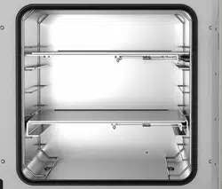
6.1 Vacuum expansion racks and rack holders ...................................................................................... 53
6.2 Mounting the pressure regulator ....................................................................................................... 54
6.3 Connecting compressed air supply for sweeping the area for electrical equipment, the preheating
chamber, and the controller housing ................................................................................................. 56
6.4 Pump module (option) ....................................................................................................................... 57
6.4.1 Mounting ................................................................................................................................. 58
6.4.2 Achieving equipotential bonding acc. to the grounding plan .................................................. 58
6.4.3 Connection of an extraction system at the pump module....................................................... 59
6.5 Vacuum connection ........................................................................................................................... 59
6.5.1 Instructions for using vacuum pumps ..................................................................................... 59
6.5.2 Vacuum pump VP4 (option) .................................................................................................... 61
6.5.3 Installation of the vacuum pump VP4 in the pump module (option) ....................................... 62
6.5.4 Note on the use of a flame arrester ........................................................................................ 64
6.5.5 ATEX connection kit for vacuum pump VP4 (option) ............................................................. 64
6.6 Connecting inert gas supply .............................................................................................................. 64
6.7 Mounting the tilt protection holders ................................................................................................... 65
6.8 Achieving equipotential bonding / Grounding concept ...................................................................... 66
6.9 Electrical connection ......................................................................................................................... 68
7. EXPLOSION SAFETY TESTS BEFORE COMMISSIONING ............................... 70
7.1 Scope of the functional test ............................................................................................................... 70
7.2 Explosion protection plan .................................................................................................................. 70
7.3 Objective of testing ............................................................................................................................ 71
7.4 Testing before initial commissioning ................................................................................................. 71
7.4.1 Scope of the test ..................................................................................................................... 71
7.4.1.1 Testing the plausibility of the explosion protection plan and measures ............................ 71
7.4.1.2 Verifying the implementation of measures ........................................................................ 71
7.4.1.3 Checking the deadlines for the recurring tests .................................................................. 72
7.4.1.4 Verifying the maintenance plan ......................................................................................... 72
7.4.2 Tests of technical ventilation systems, gas warning devices, inerting devices, devices,
protective systems or safety, control or regulating devices, and other technical devices for
explosion protection ........................................................................................................... 73
7.5 Inspection after changes requiring review ........................................................................................ 73
7.6 Recurring tests for the explosive safety of the system ..................................................................... 73
8. FUNCTIONAL OVERVIEW AND MENU STRUCTURE OF THE CONTROLLER 74
8.1 Operating functions in normal display ............................................................................................... 75
8.2 Display views: Normal display, program display, chart-recorder display .......................................... 76
8.3 MB2 controller icons overview .......................................................................................................... 77
8.4 MB2 controller operating modes ....................................................................................................... 79
8.4.1 MB2 controller menu structure ................................................................................................ 79
8.4.2 Main menu .............................................................................................................................. 80
8.4.3 “Settings” submenu ................................................................................................................. 81
8.4.4 “Service” submenu .................................................................................................................. 81
8.5 Principle of controller entries ............................................................................................................. 82
8.6 Performance during and after power failures .................................................................................... 82

VDL (E3.1) 10/2020 Page 4/196
9. START UP AND PERFORMING THE DRYING PROCESS ................................ 83
9.1 Requirements for safe commissioning .............................................................................................. 83
9.2 Overview of the drying process ......................................................................................................... 84
9.3 Sweeping the area for electrical equipment, the preheating chamber, and the controller housing
(triangular instrument box) with compressed air ............................................................................... 86
9.3.1 Setting the pressure regulator for sweeping with compressed air .......................................... 86
9.3.2 Sweeping before starting up / restarting the chamber ............................................................ 87
9.3.3 Sweeping during chamber operation ...................................................................................... 87
9.3.4 Sweeping after completion of chamber operation (recommended): ....................................... 88
9.4 Condition after establishing the power connection ........................................................................... 88
9.5 Standby mode Turning on and off the vacuum drying oven ............................................................. 89
9.6 Controller settings upon start up ....................................................................................................... 90
9.7 Loading.............................................................................................................................................. 91
9.8 Evacuation......................................................................................................................................... 93
9.9 Breaking the vacuum (flooding) ........................................................................................................ 93
9.9.1 Ventilation after completing the drying procedure (flooding with ambient air or inert gas) ..... 93
9.9.2 Operation with inert gas .......................................................................................................... 93
9.9.3 Ventilation / breaking the vacuum in case of a power failure ................................................. 94
9.9.4 Ventilation before completing the drying procedure (flooding with ambient air or inert gas) .. 94
9.10 Unloading the loading material ......................................................................................................... 95
9.11 Removing the full condensate catchpot of the pump ........................................................................ 96
9.12 Preparing a new drying process ....................................................................................................... 96
10. SET-POINT ENTRY .............................................................................................. 97
10.1 Set-point entry through the “Setpoints” menu ................................................................................... 97
10.2 Direct setpoint entry via Normal display ............................................................................................ 98
11. SETTING SPECIAL CONTROLLER FUNCTIONS .............................................. 99
11.1 Menu structure .................................................................................................................................. 99
11.1.1 “Functions on/off” menu .......................................................................................................... 99
11.1.2 “Control on/off” menu ............................................................................................................ 100
11.2 Using the optional universal connection “GAS/AIR 2” for ventilation .............................................. 100
11.3 Close all valves ............................................................................................................................... 101
11.4 Activating / deactivating temperature control .................................................................................. 101
11.5 Activating / deactivating pressure control ....................................................................................... 102
11.6 Drying monitoring ............................................................................................................................ 103
12. AUTHORIZATION LEVELS AND PASSWORD PROTECTION ........................ 105
12.1 User management, authorization levels and password protection ................................................. 105
12.2 Log in ............................................................................................................................................... 107
12.3 Log out ............................................................................................................................................ 108
12.4 User change .................................................................................................................................... 109
12.5 Password assignment and password change................................................................................. 109
12.5.1 Password change ................................................................................................................. 109
12.5.2 Deleting the password for an individual authorization level .................................................. 111
12.5.3 New password assignment for “service” or “admin” authorization level when the password
function was deactivated ................................................................................................. 112
12.6 Activation code ................................................................................................................................ 113
13. GENERAL CONTROLLER SETTINGS AND INFORMATION ........................... 114
13.1 Selecting the controller’s menu language ....................................................................................... 114
13.2 Setting date and time ...................................................................................................................... 114
13.3 Selecting the temperature unit ........................................................................................................ 116
13.4 Display configuration ....................................................................................................................... 116
13.4.1 Adapting the display parameters .......................................................................................... 116
13.4.2 Touchscreen calibration ........................................................................................................ 117
13.5 Event list .......................................................................................................................................... 118
13.6 Service contact page ....................................................................................................................... 118
13.7 Current operating parameters ......................................................................................................... 119
13.8 Technical chamber information ....................................................................................................... 119

VDL (E3.1) 10/2020 Page 5/196
14. TEMPERATURE SAFETY DEVICES ................................................................. 120
14.1 Safety temperature limiter (TL) class 2 ........................................................................................... 120
14.2 Overtemperature safety controller class 2 ...................................................................................... 120
14.2.1 Safety controller mode .......................................................................................................... 120
14.2.2 Setting the safety controller .................................................................................................. 121
14.2.3 Message and measures in the state of alarm ....................................................................... 122
14.2.4 Function check ...................................................................................................................... 122
15. TOLERANCE RANGE SETTINGS ..................................................................... 122
15.1 Setting the alarm delay times and the tolerance ranges ................................................................. 122
15.1.1 Alarm condition ..................................................................................................................... 123
16. NOTIFICATION AND ALARM FUNCTIONS ...................................................... 123
16.1 Information messages ..................................................................................................................... 123
16.2 Alarm messages ............................................................................................................................. 125
16.3 Resetting an alarm .......................................................................................................................... 126
16.4 Activating / deactivating the audible alarm (buzzer) ....................................................................... 126
16.5 Test alarm of the safety temperature limiter (TL) ............................................................................ 127
17. TIMER PROGRAM (STOPWATCH FUNCTION) ............................................... 129
17.1 Starting a timer program ................................................................................................................. 129
17.1.1 Performance during program delay time .............................................................................. 130
17.2 Stopping a running timer program .................................................................................................. 130
17.2.1 Pausing a running timer program ......................................................................................... 130
17.2.2 Cancelling a running timer program ...................................................................................... 130
17.3 Performance after the end of the program ...................................................................................... 130
18. TIME PROGRAMS ............................................................................................. 131
18.1 Starting an existing time program ................................................................................................... 131
18.1.1 Performance during program delay time .............................................................................. 132
18.2 Stopping a running time program .................................................................................................... 132
18.2.1 Pausing a running time program ........................................................................................... 132
18.2.2 Cancelling a running time program ....................................................................................... 132
18.3 Performance after the end of the program ...................................................................................... 132
18.4 Creating a new time program .......................................................................................................... 133
18.5 Program editor: program management ........................................................................................... 133
18.5.1 Deleting a time program........................................................................................................ 134
18.6 Section editor: section management ............................................................................................... 135
18.6.1 Add a new program section .................................................................................................. 136
18.6.2 Copy and insert or replace a program section ...................................................................... 136
18.6.3 Deleting a program section ................................................................................................... 137
18.7 Value entry for a program section ................................................................................................... 138
18.7.1 Section duration .................................................................................................................... 138
18.7.2 Set-point ramp and set-point step ......................................................................................... 139
18.7.3 Special controller functions ................................................................................................... 140
18.7.4 Setpoint entry ........................................................................................................................ 141
18.7.5 Tolerance range .................................................................................................................... 141
18.7.6 Repeating one or several sections within a time program .................................................... 142
18.7.7 Saving the time program ....................................................................................................... 143
19. WEEK PROGRAMS ........................................................................................... 143
19.1 Starting an existing week program .................................................................................................. 144
19.2 Cancelling a running week program ............................................................................................... 144
19.3 Creating a new week program ........................................................................................................ 145
19.4 Program editor: program management ........................................................................................... 146
19.4.1 Deleting a week program ...................................................................................................... 147
19.5 Section editor: section management ............................................................................................... 147
19.5.1 Add a new program section .................................................................................................. 148
19.5.2 Copy and insert or replace a program section ...................................................................... 149
19.5.3 Deleting a program section ................................................................................................... 149

VDL (E3.1) 10/2020 Page 6/196
19.6
Value entry for a program section in the Section view .................................................................... 149
19.6.1 Set-point ramp and set-point step modes ............................................................................. 150
19.6.2 Weekday ............................................................................................................................... 150
19.6.3 Start time ............................................................................................................................... 150
19.6.4 Setpoint entry ........................................................................................................................ 151
19.6.5 Special controller functions ................................................................................................... 151
20. NETWORK AND COMMUNICATION ................................................................ 152
20.1 Ethernet ........................................................................................................................................... 152
20.1.1 Configuration ......................................................................................................................... 152
20.1.2 Display of MAC address ....................................................................................................... 153
20.2 Web server ...................................................................................................................................... 153
20.3 E-Mail .............................................................................................................................................. 154
21. USB MENU: DATA TRANSFER VIA USB INTERFACE ................................... 155
21.1 Using the USB connection during chamber operation .................................................................... 155
22. CHART RECORDER DISPLAY ......................................................................... 156
22.1 Views ............................................................................................................................................... 156
22.1.1 Show and hide legend .......................................................................................................... 156
22.1.2 History display ....................................................................................................................... 156
22.2 Setting the parameters .................................................................................................................... 158
23. REFERENCE MEASUREMENTS ...................................................................... 159
23.1 Checking the temperature in the inner chamber ............................................................................. 159
23.1.1 Checking the controller display ............................................................................................. 159
23.1.2 Checking the spatial temperature exactitude ....................................................................... 159
23.1.3 Checking the function of the manometer for compressed air sweeping ............................... 160
24. OPTIONS ............................................................................................................ 161
24.1 APT-COM™ 4 Multi Management software (option) ...................................................................... 161
24.2 Analog outputs for temperature and pressure (option) ................................................................... 161
24.3 Object temperature display with flexible Pt 100 temperature sensor (option) ................................ 162
24.3.1 Connection of the object temperature sensor ....................................................................... 162
24.3.2 Display on the MB2 controller ............................................................................................... 163
25. CLEANING AND DECONTAMINATION ............................................................ 163
25.1 Safety instructions on cleaning and decontamination ..................................................................... 163
25.2 Cleaning .......................................................................................................................................... 164
25.3 Decontamination / chemical disinfection ......................................................................................... 165
26. MAINTENANCE AND SERVICE, TROUBLESHOOTING, REPAIR, TESTING . 167
26.1 General information, personnel qualifications ................................................................................. 167
26.2 Simple troubleshooting .................................................................................................................... 168
26.3 Maintenance, Service ...................................................................................................................... 171
26.3.1 Safety instructions on maintenance work ............................................................................. 171
26.3.2 Maintenance intervals ........................................................................................................... 172
26.4 Service Reminder ............................................................................................................................ 172
26.4.1 BINDER Service contact data ............................................................................................... 172
26.5 Sending the chamber back to BINDER GmbH ............................................................................... 173
27. DISPOSAL.......................................................................................................... 173
27.1 Disposal of the transport packing .................................................................................................... 173
27.2 Decommissioning ............................................................................................................................ 173
27.3 Disposal of the chamber in the Federal Republic of Germany ....................................................... 174
27.4 Disposal of the chamber in the member states of the EU except for the Federal Republic of
Germany.......................................................................................................................................... 175
27.5 Disposal of the chamber in non-member states of the EU ............................................................. 176
28. TECHNICAL DESCRIPTION .............................................................................. 176
28.1 Factory calibration and adjustment ................................................................................................. 176
28.2 Over current protection ................................................................................................................... 177

VDL (E3.1) 10/2020 Page 7/196
28.3 VDL / VDL-UL technical data .......................................................................................................... 177
28.4 Equipment and options (extract) ..................................................................................................... 179
28.5 Accessories and spare parts (extract) ............................................................................................ 180
28.6 Dimensions...................................................................................................................................... 182
28.6.1 VDL 23 .................................................................................................................................. 182
28.6.2 VDL 56 .................................................................................................................................. 183
28.6.3 VDL 115 ................................................................................................................................ 184
29. INDEX ................................................................................................................. 185
30. CERTIFICATES AND DECLARATIONS OF CONFORMITY ............................. 187
30.1 EU Declaration of Conformity.......................................................................................................... 187
31. PRODUCT REGISTRATION .............................................................................. 190
32. CONTAMINATION CLEARANCE CERTIFICATE ............................................. 191
32.1 For chambers located outside USA and Canada ........................................................................... 191
32.2 For chambers located in USA and Canada .................................................................................... 194
List of figures
Figure 1: Position of labels on the chamber (example) ............................................................................... 12
Figure 2: Type plate (example of VDL 115) ................................................................................................ 13
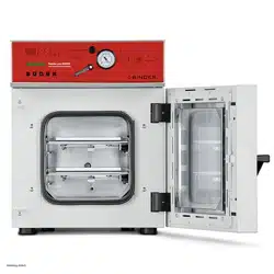
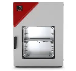
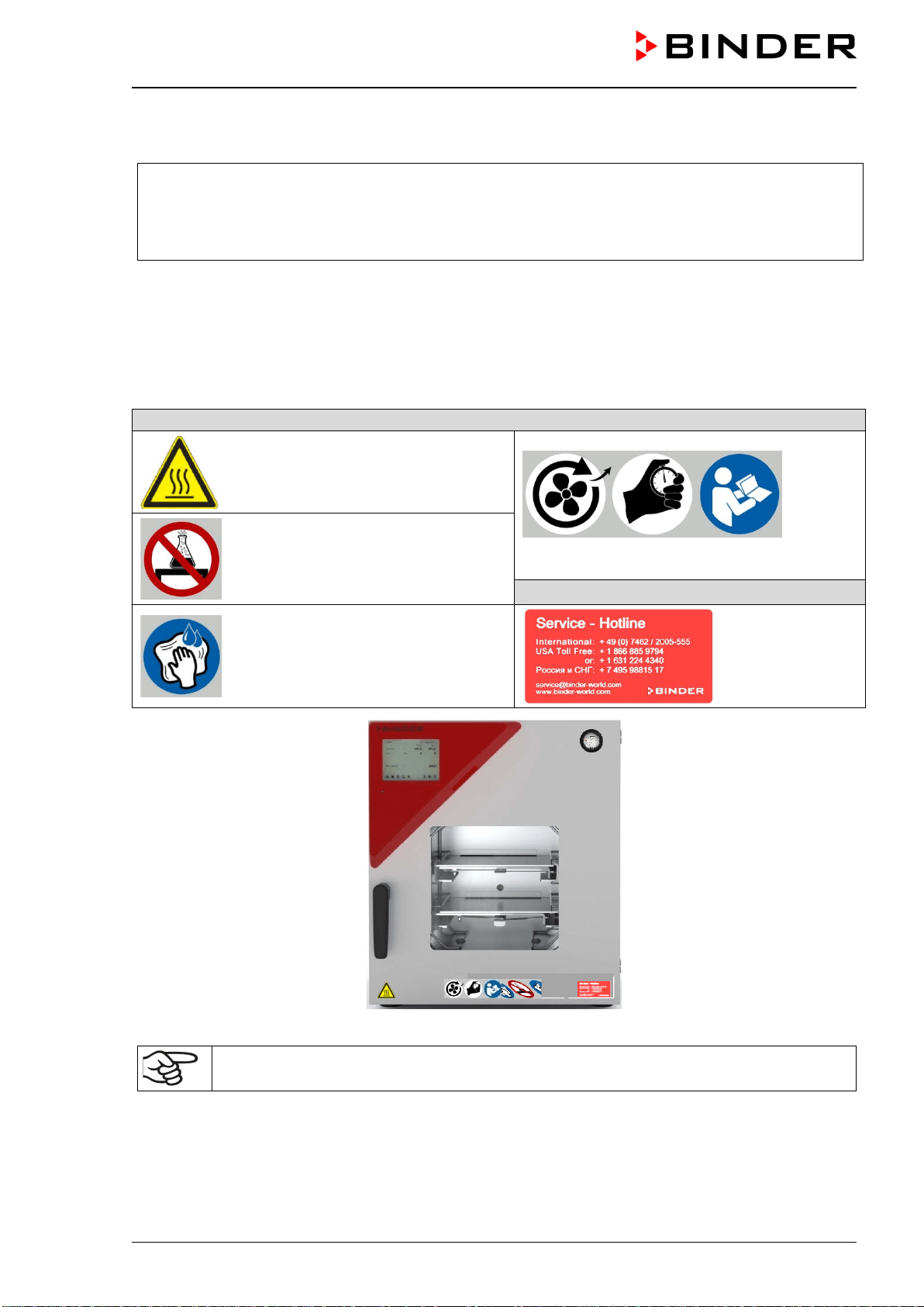
Figure 3: VDL 115 with MB2 controller ....................................................................................................... 41
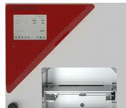
Figure 4: Triangular instrument box (controller housing) with MB2 program controller and USB interface 42
Figure 5: Chamber rear (example: VDL 115) .............................................................................................. 42
Figure 6: Rear connection panel VDL with options ..................................................................................... 43
Figure 7: Area classification of the closed chamber (view without housing, insulation, heater and outer
chamber) ...................................................................................................................................... 45
Figure 8: Area classification in the surroundings of the chamber (schematic representation, standard
device) .......................................................................................................................................... 46
Figure 9: Area classification in the surroundings of the chamber during operation (example) ................... 47
Figure 10: Operating the expansion racks .................................................................................................. 53
Figure 11: Mounting the pressure regulator on the chamber rear .............................................................. 55
Figure 12: Compressed air connection on the pressure regulator .............................................................. 56
Figure 13: VDL mounted on pump module ................................................................................................. 57
Figure 14: Pump module, rear view (example size 115) ............................................................................ 57
Figure 15: Position of the Vacuum connection (6) on the chamber rear (example size 56) ....................... 59
Figure 16: Vacuum pump VP 4 (MZ2C EX) ................................................................................................ 61
Figure 17: Variable length of the tilt protection holder depending on the bend .......................................... 65
Figure 18: Possibilities of grounding (schematic representation) ............................................................... 66
Figure 19: Mounting the grounding cable on the VDL................................................................................. 67
Figure 20: Normal display of the MB2 program controller (sample values) ................................................ 74
Figure 21: Operating functions of the MB2 controller in normal display (example values) ......................... 75
Figure 22: Pressure regulator and sweeping plug for compressed air sweeping on the chamber rear ..... 86
Figure 23: analog pressure display (manometer) for compressed air sweeping on the chamber front ...... 86
Figure 22: Pressure regulator with defined setting at the upper stop ......................................................... 87
Figure 24: Schematic timing of the drying process and drying monitoring ............................................... 103
Figure 25: Pressure regulator and sweeping plug for compressed air sweeping on the chamber rear ... 160
Figure 26: Connection cable on the “Analog output” (3b) connection...................................................... 161
Figure 26: SUB-D socket for the analog outputs option ............................................................................ 161
Figure 29: Measuring connection (12) with measuring access port .......................................................... 162
Figure 29: Connection cable on the “Object temperature input” connection (3a) ..................................... 162
Figure 29: Plug connection between measuring access port and Lemo socket ....................................... 162
Figure 29: Cable connection of the optional Pt 100 sensor ...................................................................... 162
VDL (E3.1) 10/2020 Page 8/196
Dear customer,
For the correct operation of the VDL vacuum drying oven, it is important that you read this operating manual
completely and carefully and observe all instructions as indicated. Failure to read, understand and follow
the instructions may result in personal injury. It can also lead to damage to the chamber and/or poor equip-
ment performance.
1. Safety
1.1 Personnel Qualification
The chamber must only be installed, tested, and started up by personnel qualified for assembly, startup,
and operation of the chamber with additional skills in explosion protection (ATEX). Qualified personnel are
persons whose professional education, knowledge, experience and knowledge of relevant standards allow
them to assess, carry out, and identify any potential hazards in the work assigned to them. They must have
been trained and instructed, and be authorized, to work on the chamber. This includes a basic knowledge
of explosion protection (ATEX training), instruction based on the risk assessment by the operator (chap.
2.2) and knowledge of the Operating Instruction by the operator.
The device shall only be operated by laboratory personnel especially trained for this purpose and familiar
with all precautionary measures required for working acc. to ATEX Directive 2014/37/EU. Observe the
national regulations on minimum age of laboratory personnel.
1.2 Operating manual
This operating manual is part of the components of delivery. Always keep it handy for reference in the
vicinity of the chamber. If selling the unit, hand over the operating manual to the purchaser.
To avoid injuries and property damage observe the safety instructions of the operating manual. Failure to
follow instructions and safety precautions can lead to significant risks and to the loss of explosion protection.
DANGER
Explosion hazard due to failure to observe the instructions and safety precautions.
Serious injuries and chamber damage. Risk of death.
Observe the safety instructions in this Operating Manual.
Follow the operating procedures in this Operating Manual.
Carefully read the complete operating instructions of the chamber prior to installing and
using the chamber.
Keep the operating manual for future reference.
Make sure that all persons who use the chamber and its associated work equipment have
read and understood the Operating Manual.
This Operating Manual is supplemented and updated as needed. Always use the most recent version of
the Operating Manual. When in doubt, call the BINDER Service Hotline for information on the up-to-date-
ness and validity of this Operating Manual.

VDL (E3.1) 10/2020 Page 9/196
1.3 Legal considerations
This operating manual is for informational purposes only. It contains information for correct and safe in-
stalling, start-up, operation, decommissioning, cleaning and maintenance of the product. The content of
this operating manual takes into account the applicable regulatory requirements and the latest technology.
Note: the contents and the product described are subject to change without notice.
Understanding and observing the instructions in this operating manual are prerequisites for hazard-free use
and safety during operation and maintenance. Images are to provide basic understanding. They may devi-
ate from the actual version of the chamber. The actual scope of delivery can, due to optional or special
design, or due to recent technical changes, deviate from the information and illustrations in these instruc-
tions this operating manual. In no event shall BINDER be held liable for any damages, direct or incidental
arising out of or related to the use of this manual.
This operating manual cannot cover all conceivable applications. If you would like additional information,
or if special problems arise that are not sufficiently addressed in this manual, please ask your dealer or
contact us directly, e.g. by phone at the number located on page one of this manual.
Furthermore, we emphasize that the contents of this operating manual are not part of an earlier or existing
agreement, description, or legal relationship, nor do they modify such a relationship. All obligations on the
part of BINDER derive from the respective purchase contract, which also contains the entire and exclusively
valid statement of warranty administration and the general terms and conditions, as well as the legal regu-
lations valid at the time the contract is concluded. The statements in this manual neither augment nor
restrict the contractual warranty provisions.
Furthermore, relevant national and international regulations on occupational safety apply. The operator
must know, comply with, and implement these requirements. In particular, this includes the provisions of
ATEX Operational Directive 1999/92/EC (“ATEX 137”) (implemented for Germany in the Industrial Safety
Regulation (BetrSichV) and the Ordinance on Hazardous Substances (GefStoffV)). The operator is respon-
sible for choosing suitable work equipment for the areas classified as explosion hazards and for installing
and operating equipment in accordance with respective requirements.
Limitation of liability
BINDER GmbH is not liable for any damage arising from the following causes:
• Non-observance of Instruction Manual
• Improper use
• Improper installation, setup, maintenance, repair
• Inspections not being performed (testing before initial commissioning, recurring tests, testing before
recommissioning
• Negligence or willful intent
• Incorrect response to malfunctions
• Assignment of improperly or insufficiently trained personnel
• Technical changes and modifications made by the operator and not approved by the manufacturer
• Use of non-approved accessories and replacement parts
We reserve the right to technical changes as part of improvements to operating characteristics and further
development.
Have repairs performed only by experts authorized by BINDER. Repaired chambers must comply with the
quality standard specified by BINDER. In particular, carry out an inspection before recommissioning after
maintenance or repairs. These can only be performed by the manufacturer or specially trained personnel
(in Germany: Qualified Persons per BetrSichVO).
VDL (E3.1) 10/2020 Page 10/196
1.4 Structure of the safety instructions
In this operating manual, the following safety definitions and symbols indicate dangerous situations follow-
ing the harmonization of ISO 3864-2 and ANSI Z535.6.
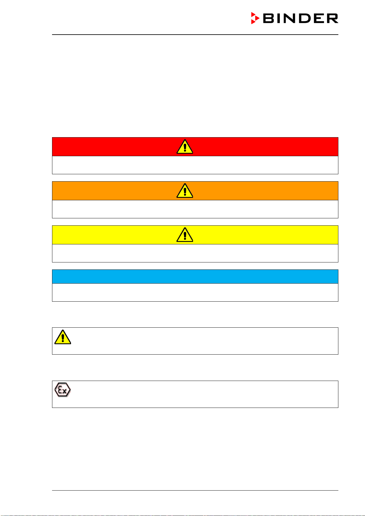
1.4.1 Signal word panel
Depending on the probability of serious consequences, potential dangers are identified with a signal word,
the corresponding safety color, and if appropriate, the safety alert symbol.
DANGER
Indicates an imminently hazardous situation that, if not avoided, will result in death or serious (irreversi-
ble) injury.
WARNING
Indicates a potentially hazardous situation which, if not avoided, could result in death or serious (irre-
versible) injury.
CAUTION
Indicates a potentially hazardous situation which, if not avoided, may result in moderate or minor (re-
versible) injury.
NOTICE
Indicates a potentially hazardous situation, which, if not avoided, may result in damage to the product
and/or its functions or to property in its proximity.
1.4.2 Safety alert symbol
Use of the safety alert symbol indicates a risk of injury
Observe all measures that are marked with the safety alert symbol in order to avoid death or
injury.
1.4.3 Explosion protection symbol
Use of the explosion protection symbol warns against explosion hazards.
Observe all measures in this operating manual to avoid the formation of explosive atmosphere
as well as explosions.
VDL (E3.1) 10/2020 Page 11/196
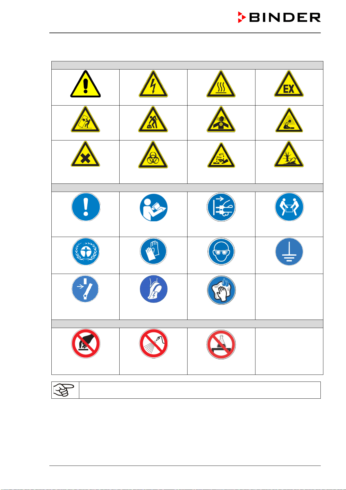
1.4.4 Pictograms in this manual
Warning signs
Danger of injury
Electrical hazard
Hot surface
Explosive atmosphere
Stability hazard
Lifting hazard
Inhalation hazard
Suffocation hazard
Harmful substances
Biohazard
Risk of corrosion and /
or chemical burns
Pollution Hazard
Mandatory action signs
Mandatory regulation
Read operating
instructions
Disconnect the power
plug
Lift with several persons
Environment protection
Wear protective gloves
Wear eye protectors
Ground before use
Release before mainte-
nance or repairs
Wear ESD shoes
(antistatic shoes)
Wipe with damp cloth
only
Prohibition signs
Do NOT touch
Do NOT spray with
water
Do not place anything
on the chamber
Information to be observed in order to ensure optimum function of the product.
VDL (E3.1) 10/2020 Page 12/196
1.4.5 Word message panel structure
Type and cause of hazard.
Possible consequences.
∅ Instruction how to avoid the hazard: prohibition
Instruction how to avoid the hazard: mandatory action
Observe all other notes and information not necessarily emphasized in the same way, in order to avoid
disruptions that could result in direct or indirect injury or property damage.
1.5 Localization / position of safety labels on the chamber
The following labels are located on the chamber door:
Safety labels
Hot surface
Observe sweeping time, read operating manual
Do not place anything on the chamber
Service label
Wipe surfaces with damp cloth only
Figure 1: Position of labels on the chamber (example)
Keep safety labels complete and legible.
Replace safety labels that are no longer legible. Contact BINDER Service for these replacements.
VDL (E3.1) 10/2020 Page 13/196
1.6 Type plate
Position of type plate: left chamber side (seen from front), at the bottom right-hand.
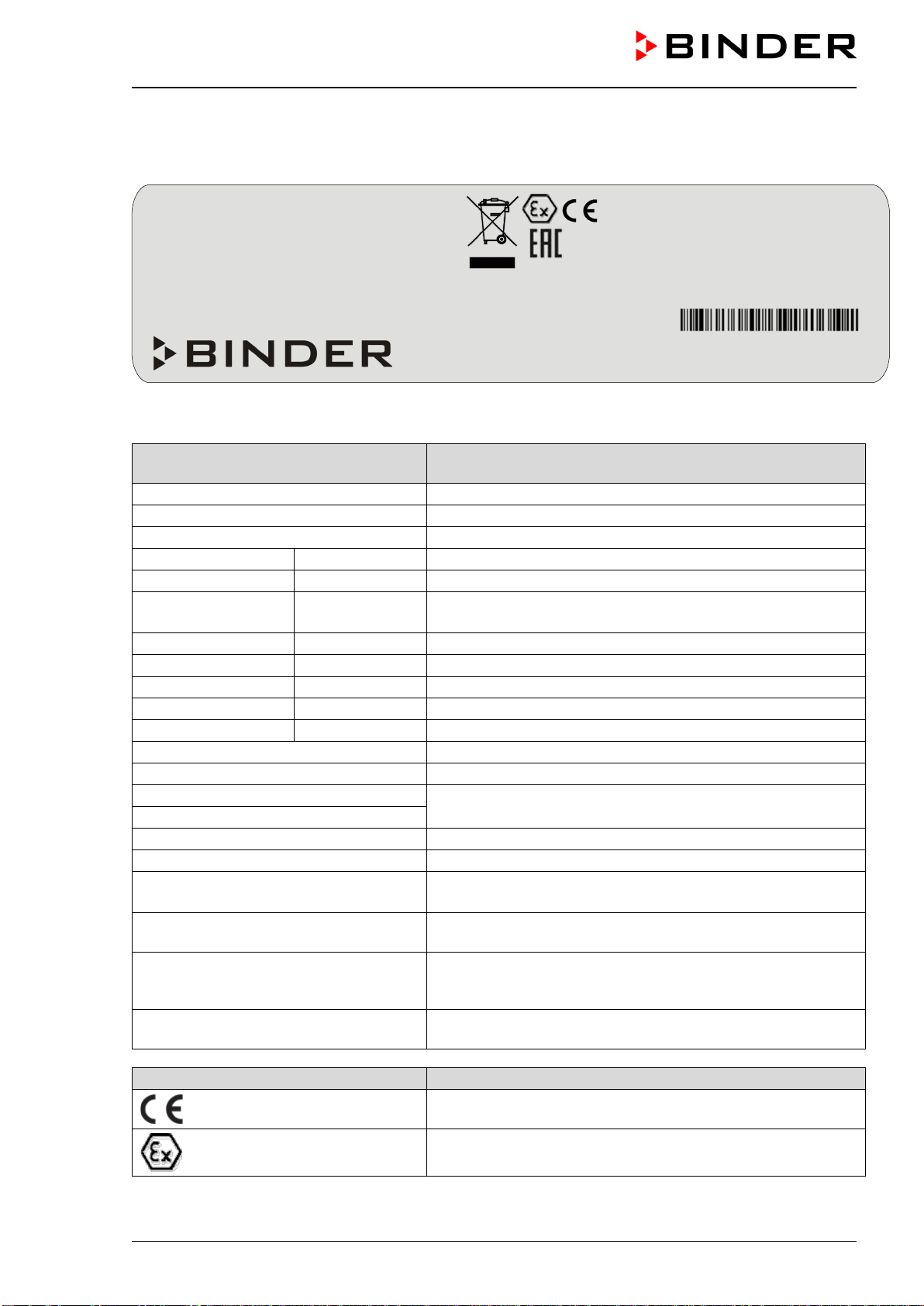
Figure 2: Type plate (example of VDL 115)
Indications of the type plate
(example)
Information
BINDER
Manufacturer: BINDER GmbH
VDL 115
Model designation
Vacuum Drying Oven
Chamber name: Vacuum drying oven
Serial No.
000000000000
Serial No. of the chamber
Built
2020
Year of construction
Nominal temperature
110 °C
230 °F
Nominal temperature
IP protection
20
Type of IP protection acc. to standard EN 60529
Temp. safety device
DIN 12880
Temperature safety device acc. to standard DIN 12880:2007
Class
2.0
Class of temperature safety device
Art. No.
9630-0011
Art. No. of the chamber
Project No.
---
Optional: Special application acc. to project no.
1,60 kW
Nominal power
7,0 A
Nominal current
230 V / 50 Hz
Nominal voltage +/- 10% at the indicated power frequency
230 V / 60 Hz
1 N ~
Current type
Explosion proof inner chamber
Explosion proof inner chamber
Ex classification acc. to 2014/34/EU
Ex II 2/3/- G IIB T3 Gb/Gc/- X
Ex classification according to ATEX Directive 2014/34/EU
Max. temp. of inner chamber surface in
cat. 2: +160 °C
Maximum temperature of the inner chamber surfaces:
160 °C / 320 °F (Device category 2)
Max. temp. of heating chamber
surface in cat. 3: +195 °C
Maximum temperature of the outer surface of the preheating
chamber (outer chamber): 185 °C / 365 °F (Device category
3)
Temp. class T3
Temperature class acc. to IEC 60079-0 for the entire cham-
ber
Symbol on the type plate
Information
CE conformity marking
Explosion protection symbol. Ex classification acc. to ATEX
Directive 2014/34/EU
Nominal temp.
IP protection
Safety device
Class
Art. No.
Project No.
Built
110 °C
230 °F
20
DIN 12880
2.0
9630-0011
2020
1,60 kW / 7,0 A
EXPLOSION PROOF INNER CHAMBER
EX CLASSIF. ACC. TO 2014/34/EU
EX II 2/3/- G IIB T3 GB/GC/- X
MAX.
TEMP. OF INNER CHAMBER
SURFACE IN CAT 2: +160 °C
MAX. TEMP. OF HEATING CHAMBER
SURFACE IN CAT 3: +195 °C
TEMP. CLASS T3
230 V / 50 Hz
230 V / 60 Hz
1 N ~
VACUUM DRYING OVEN
BINDER GmbH
Im Mittleren Ösch 5
78532 Tuttlingen / Germany
www.binder-world.com
VDL 115
E3.1
Serial No. 00000000000000
Made in Germany

VDL (E3.1) 10/2020 Page 14/196
Symbol on the type plate
Information
Electrical and electronic equipment manufactured / placed on
the market in the EU after 13 August 2005 and to be dis-
posed of in a separate collection according to Directive
2012/19/EU on waste electrical and electronic equipment
(WEEE).
The chamber is certified according to Customs Union Tech-
nical Regulation (CU TR) for the Eurasian Economic Union
(Russia, Belarus, Armenia, Kazakhstan Kyrgyzstan).
1.7 Safety instructions on installing and operating the vacuum drying oven
With regard to operating the vacuum drying oven VDL and to the installation location, please observe the
relevant national regulations (for Germany in particular: DGUV guidelines 213-850 on safe working in la-
boratories, issued by the employers’ liability insurance association; Industrial Safety Regulation (Be-
trSichV); Ordinance on Hazardous Substances (GefStoffV); Technical Regulations on Industrial Safety and
Health (TRBS 1201 Part 1).
The central element of the Industrial Safety Regulation is the risk assessment performed by competent
personnel which enables an employer to evaluate risks that may arise before using work equipment and to
derive necessary and suitable tests and measures.
Explosion protection plan
The explosion protection plan to be created by the operator represents the entirety of the technical and
organizational measures for explosion protection determined and specified on the basis of the risk assess-
ment. In accordance with ATEX Operational Directive 1999/92/EC, these measures serve
• to prevent the formation of or to limit explosive atmospheres or to limit hazardous explosive mixtures
• to avoid the combustion of explosive atmospheres
• to limit the spread of an explosion and to minimize its effects on personnel in order to ensure the health
and safety of employees
The explosion protection document serves to document the results of the risk assessment in accordance
with § 6 Para. 9 GefStoffV (for Germany).
BINDER GmbH is only responsible for the safety features of the chamber provided skilled electricians or
qualified personnel authorized by BINDER perform all maintenance and repair, and if components relating
to chamber safety are replaced in the event of failure with original spare parts.
To operate the chamber, use only original BINDER accessories or accessories from third-party suppliers
authorized by BINDER. The user is responsible for any risk caused by using unauthorized accessories.
1.7.1 Safety instructions on installation and ambient conditions of the chamber
Familiarize yourself with the local conditions, particularly allocation to a defined potentially explosive area
(zones) and the according technical safety requirements. During installation, commissioning and operation
of the vacuum drying oven and the connected vacuum pump or in-house vacuum supply, always follow the
requirements defined by the classification of the installation site.
VDL (E3.1) 10/2020 Page 15/196
1.7.1.1 Aeration / ventilation of the installation site
NOTICE
Danger of overheating due to lack of aeration.
Damage to the chamber.
∅ Do NOT install the chamber in unventilated recesses.
Ensure sufficient ventilation for dispersal of heat.
Observe the prescribed minimum distances when installing the chamber (chap. 5.1)
The vacuum drying ovens were constructed in accordance with the applicable VDE regulations and were
routinely tested in accordance with VDE 0411-1 (IEC 61010-1). The production underlies an internal mon-
itoring according to ATEX Directive 2014/34/EU appendix VIII.
For the user there is no risk of temporary overvoltages in the sense of EN 61010-1:2010.
1.7.1.2 No installation in potentially explosive areas of Zone 1 or 0
Even when the equipment is used properly, there exists a residual risk of explosion that cannot be excluded,
particularly in relation to the environment of the chamber. To minimize this risk, strictly observe the legal
regulations about how to select an appropriate location. Do not install and operate the vacuum drying oven
VDL in occasionally or continuously / for long periods / frequently potentially explosive areas.
DANGER
Explosion hazard due to combustible dusts or explosive mixtures in the vicinity of
the equipment.
Serious injury or death from burns and / or explosion pressure.
∅ Do NOT operate the chamber in in occasionally or continuously / for long periods / fre-
quently potentially explosive areas. It is not intended for installation in a zone 1 or 0.
KEEP combustible dusts AWAY from the equipment
Make sure that air-solvent mixtures are NOT occasionally or continuously / for long pe-
riods / frequently in the vicinity of the equipment.
Reliably prevent spreading of an explosive atmosphere to unprotected areas (see chap.
3.5).
Strictly observe the relevant legal regulations about how to select an appropriate loca-
tion.
1.7.1.3 Equipotential bonding according to the grounding concept
The walkable installation and operating surface of the chamber must be conductive. This installation and
operating surface must be connected to the vacuum drying oven according to the grounding concept (chap.
6.8). Cyclic measurements of the equipotential bonding are required.
DANGER
Explosion hazard by electric sparking due to missing or improperly implemented
equipotential bonding.
Serious injury or death from burns and / or explosion pressure.
Connect all equipment elements in the installation and operating area (VDL / pump
module / pump) with the conductive surface and/or with each other. Proceed according
to the grounding concept (Chap. 6.8).
Measure the equipotential bonding prior to commissioning the equipment.
Provide cyclic measurements of the equipotential bonding.
VDL (E3.1) 10/2020 Page 16/196
1.7.1.4 Accessibility to the disconnection from the power grid
To completely separate the chamber from the power supply, you must disconnect the power plug. Install
the chamber in a way that the power plug is easily accessible and can be easily pulled in case of danger.
The chamber’s power plug is unprotected. The electrical connection must therefore be established outside
a zone.
1.7.1.5 Technical ventilation (extraction)
The operator shall provide active extraction (technical ventilation according to country-specific regulations
(TRBS 2152 Part 2 for Germany) before commissioning the chamber. Extraction must include the entire
installation area of the vacuum drying oven and a vacuum pump. Observe the area classification in the
surroundings of the chamber (chap. 3.5.3). Extraction must be active during the entire chamber operation.
Operation, loading and unloading of the loading material and removal of the filled condensate catchpot of
the pump must always take place under technical ventilation. If the technical ventilation fails, automatically
switch off power to the chamber.
This will prevent spreading of an explosive atmosphere to unprotected areas (see chap. 3.5).
DANGER
Explosion hazard due to the spread of an explosive atmosphere to unprotected ar-
eas and ignition due to electric sparking or hot surfaces.
Serious injury or death from burns and / or explosion pressure.
Provide active suction (technical ventilation according to country-specific regulations
(TRBS 2152 Part 2 for Germany) prior to commissioning the chamber.
Extraction must include the entire installation area of the vacuum drying oven.
Make sure that the chamber is automatically turned off if the technical ventilation fails.
1.7.2 Safety instructions on compressed air supply
Before starting / restarting the chamber, the electrical installation room, preheating chamber, and controller
housing (triangular instrument box) must be swept with compressed air with maximum overpressure for a
defined time (chap. 9.3).
Sweeping the area for electrical equipment, the preheating chamber and controller housing must take place
with an overpressure of at least 25 Pa (recommendation: >40 Pa) during the entire operation of the vacuum
drying oven. Also after termination or cancellation of the drying process, continued sweeping for at least 10
minutes is recommended.
An inlet pressure of 2 bar must be provided for compressed air sweeping. The compressed air supply line
provided by the operator must be equipped with a monitoring device which clearly indicates a drop and
increase in the inlet pressure outside the permissible tolerance of ± 0.2 bar.
DANGER
Explosion hazard by solvent-containing air penetrating the electrical area of the
oven or the preheating chamber.
Serious injury or death from burns and / or explosion pressure.
Make sure that sweeping the area for electrical equipment, preheating chamber, and
controller housing with compressed air for the defined time (chap. 9.3.2) at maximum
overpressure has been done before turning on the chamber.
Make sure that sweeping the area for electrical equipment, preheating chamber, and
controller housing with compressed air with an overpressure of at least 25 Pa (recom-
mendation: >40 Pa) takes place during the entire operation.
Ensure that the operator compressed air supply line is equipped with active monitoring
of the defined inlet pressure.
VDL (E3.1) 10/2020 Page 17/196
1.7.3 Safety instructions on vacuum supply
Prior to commissioning the chamber make sure that all relevant national and international regulations are
observed. Within the European Union, units that will be operated in potentially explosive areas have to meet
the requirements of ATEX Directive 2014/34/EU.
If combustible solvent is introduced into the drying chamber, the vacuum pump must be constructed in a
suitable explosion-proof manner.
Observe the safety instructions of the pump manufacturer.
1.7.3.1 Selection and location of a suitable pump
The mixtures extracted from the inner chamber must be carried away making sure that there is no danger
by ignition of these atmospheres. Sparking in the pump motor or the switching elements, electrostatic dis-
charges, as well as hot pump parts can ignite solvent vapors in the event of an error. To minimize this risk,
use an ATEX Directive 2014/34/EU compliant vacuum pump suitable for suction from Zone 0 or 1 and, if
appropriate, from the zone of its installation site.
DANGER
Explosion hazard due to the spread of an explosive atmosphere to unprotected
pump parts and ignition due to electric sparking on the pump motor or switching el-
ements, electrostatic discharges, or hot surfaces.
Serious injury or death from burns and / or explosion pressure.
Use only suitable, explosion-proof pumps. See chap. 6.5.1.
Operate the pump in a stationary position and secure it so it is immobile.
Make sure that the suction line to the vacuum connection (6) of the VDL is fixed and
conductive.
Ensure sufficient solvent condensation, e.g., in an exhaust waste vapor condenser, to
avoid that ignitable solvent concentrations are conducted from the pump. Otherwise,
the exhaust pipe after the pump must be fixed and conductive and suction must be
done in an explosion-proof area.
Ensure equipotential bonding between the pump, the VDL vacuum drying oven and, if
appropriate, the pump module using the connections of the grounding conductors ac-
cording to the grounding concept (Chap. 6.8).
Confirm that the vacuum pump is designed for a gas inlet temperature corresponding to
the used drying temperature, or take appropriate measures to cool down the extracted
vapor before it enters the vacuum pump.
Use ATEX compliant vacuum pumps providing an integral protective device for the
pump OR Install a current-dependent, delayed protective device for the pump (for the
triggering time of this protective device, see the manufacturer’s specifications). The pro-
tective and monitoring device must not be able to turn on independently again or be re-
leased.
Use ATEX compliant vacuum pumps providing an integral explosion proof switch OR
make sure that the switch gear box is either installed outside the hazardous area or that
it is explosion proof.
The ATEX compliant vacuum pump offered by BINDER provides an integral protective device
for the pump and an integral explosion proof switch.
VDL (E3.1) 10/2020 Page 18/196
1.7.3.2 Observing the permissible gas inlet temperature
Confirm that the vacuum pump / vacuum system is designed for a gas inlet temperature corresponding to
the used drying temperature, or take appropriate measures to cool down the extracted vapor before it enters
the vacuum pump / vacuum system. If the gas inlet temperature is too high and then becomes even warmer
by compression in the pump, the resulting temperature (of the gas-solvent mixture inside the pump) could
exceed the solvent’s temperature class and auto-ignition temperature. The ATEX compliant vacuum
pumps offered by BINDER are designed for a gas inlet temperature of 40 °C / 104 °F max. Do NOT
exceed this temperature.
DANGER
Fire and explosion hazard by exceeding the auto-ignition temperature of the solvent
due to excessive gas inlet temperature
Damage to the vacuum pump. Serious injury or death from burns and / or explosion
pressure.
∅ Do NOT exceed the maximum gas inlet temperature of the pump (ATEX compliant vac-
uum pumps from BINDER: 40 °C).
When operating with a higher set-point temperature take appropriate measures to cool
down the extracted vapor before it enters into to the vacuum pump.
1.7.3.3 Technical Ventilation (extraction)
When manipulating the vacuum pump (removing the filled condensate catchpot of the pump) or in the event
of an error (e.g. dropping or spilling the filled condensate catchpot) spreading of an explosive atmosphere
to unprotected parts of the pump or the vacuum drying oven would be possible.
The operator must provide active extraction (technical ventilation according to country-specific regulations
– TRBS 2152 Part 2 for Germany) prior to commissioning and manipulating the vacuum pump. Extraction
must include the entire installation area of the vacuum drying oven, the pump and, if appropriate, the pump
module. Handling the pump always takes place under technical ventilation.
This will prevent spreading of an explosive atmosphere to unprotected chamber parts other than the defined
area (see Chap. 3.5).
DANGER
Explosion hazard due to the spread of an explosive atmosphere to unprotected
parts of the pump or the vacuum drying oven and ignition due to electric sparking
or hot surfaces.
Serious injury or death from burns and / or explosion pressure.
Provide active suction (technical ventilation according to country-specific regulations
(TRBS 2152 Part 2 for Germany) prior to commissioning the vacuum pump.
Extraction must include the entire installation area of the vacuum drying oven, the pump
and, if appropriate, the pump module.
When using the pump module, connect an extraction system to the provided exhaust
port as described in the mounting instructions of the pump module (Art. no. 7001-0137).

VDL (E3.1) 10/2020 Page 19/196
1.7.4 Safety instructions on the charging material
The temperature class of the inner chamber according to IEC 60079-0 can be T1, T2, or T3. Only introduce
substances with an auto-ignition temperature that is higher than 200 °C / 392 °F. You can use a solvent
which would form an explosive mixture with air under normal conditions.
If the auto-ignition temperature of a solvent contained in the drying material is exceeded during the drying
process, there is an immediate risk of fire and explosion. This chamber is not suitable to dry substances
with an auto-ignition temperature below 200 °C / 392 °F. Substances falling under explosion group / gas
group IIC are not permitted (e.g. carbon disulfide, hydrogen).
Combustible dusts are generally not permitted, neither in the vicinity nor as a load.
DANGER
Explosion hazard due to unsuitable drying material.
Serious injury or death from burns and / or explosion pressure.
∅ Do NOT introduce any substance with an auto-ignition temperaturebelow 200 °C / 392
°F into the chamber
∅ Do NOT introduce combustible dusts into the chamber.
∅ Do NOT introduce any substance which tends towards exothermal decomposition into
the chamber.
∅ Do NOT introduce any substance which comes under the explosive substance law into
the chamber.
∅ Do NOT introduce energy sources such as batteries or lithium-ion batteries into the
chamber.
∅ Do NOT introduce any substance which could lead to release of toxic gases into the
chamber.
Familiarize yourself with the physical and chemical properties of the charging material, as well as the con-
tained moisture constituent and its behavior with the addition of heat energy and changes in pressure. No
dangerous chemical reactions must occur during the drying process.
DANGER
Fire and explosion hazard caused by chemical reactions with the addition of heat
energy and changes in pressure.
Serious injury or death from burns and / or explosion pressure.
Make sure that no dangerous chemical reactions of the loading material can occur dur-
ing the drying process.
Familiarize yourself with any potential health risks caused by the charging material, the con-
tained moisture constituent or by reaction products that may arise during the drying process.
Take adequate measures to exclude such risks prior to putting the VDL vacuum drying oven
into operation.
VDL (E3.1) 10/2020 Page 20/196
1.7.5 Safety instructions on operating the vacuum drying oven
Note the following points before starting up the oven:
When loading the chamber and possibly at the moment of unloading, also in the context of
intended use, an explosive mixture may form in the working space. Define a safety area of
at least 1m from the chamber front and ensure active extraction (technical ventilation).
The walkable installation and operating surface of the chamber must be conductive. This
installation and operating surface must be connected to the vacuum drying oven according
to the grounding concept. Cyclic measurements of the equipotential bonding are required.
The operator must ensure an appropriate ventilation of the loading area in front of the
oven front prior to commissioning of the chamber.
Ensure that at no time any solvent vapors could enter in the area of the electrical installa-
tion room, preheating chamber, and controller housing (triangular instrument box).
Provide technical ventilation in the area of the vacuum pump stand, particularly in the areas
of the condensate catchpot (when emptying it) and the exhaust air of the vacuum pump.
The personal protective equipment (PPE) of the operating personnel must be ESD pro-
tected.
Only trained personnel with password authorization may work on the VDL vacuum drying
oven.
DANGER
Electrical hazard by water entering the chamber.
Deadly electric shock.
∅ The equipment must NOT become wet during operation, cleaning, or maintenance.
∅ Do NOT install the equipment in damp areas or in puddles.
Set up the equipment in a splash-proof manner.
DANGER
Electrical hazard due to damage to the equipment
Deadly electric shock.
∅ Do NOT insert any objects, particularly metallic objects, in louvers or other openings or
slots on the chamber
∅ Do NOT operate the chamber if the housing is damaged.
∅ Do NOT operate the chamber if the power cord is damaged.
Disconnect the chamber from the power supply in case of an obvious malfunction.
CAUTION
Danger of burning when touching the hot inner surfaces during operation.
Burns.
∅ Do NOT touch the inner surfaces or the charging material during and after operation.
VDL (E3.1) 10/2020 Page 21/196
When operating the VDL vacuum drying oven with inert gas correctly follow the technical ventilation
measures, as described in the DGUV guidelines 213-850 on safe working in laboratories (for Germany).
Do not start up the chamber without active technical ventilation .
During operation with inert gas the chamber is supplied with an oxygen displacing gas (e.g. N
2
). Inert gases
in high concentrations are hazardous to health. They are colorless and almost odorless and therefore prac-
tically imperceptible. Inhalation of inert gases can cause drowsiness up to respiratory arrest. When the O
2
content of the air decreases below 18%, there is risk of death from lack of oxygen. Any gas that might
escape has to be led out via good room ventilation or a suitable exhaust system.
DANGER
Suffocation hazard due to high concentration of inert gas.
Death by suffocation.
∅ Do NOT set up chambers in non-ventilated recesses.
Make sure that technical ventilation measures are active.
Respect the relevant regulations for handling inert gases.
When decommissioning the vacuum drying oven, shut off the inert gas supply.
If solvent-containing air penetrates the electrical area of the oven or the preheating chamber, explosions
may result.
DANGER
Explosion hazard by solvent-containing air penetrating the electrical area of the
oven or the preheating chamber.
Serious injury or death from burns and / or explosion pressure.
∅ Do NOT take the air, which will be used to supply the chamber with compressed air,
from a potentially explosive atmosphere.
∅ Ensure that the operator compressed air supply line is equipped with active monitoring
of the defined inlet pressure.
The unit must not be operated without compressed air flushing at maximum overpressure and
running compressed air flushing with active monitoring of the defined inlet pressure.
Avoid the solvent accumulation in the optional pump module as this would cause the vacuum
module to become an occasionally or continuously / for long periods / frequently potentially ex-
plosive area (Zone 0 or 1). The VDL vacuum drying oven located on top of the module is im-
plemented in Device category 3 in regards to its surroundings.
DANGER
Explosion hazard due to operating the oven with material containing solvent that
may be able to form an explosive mixture with air.
Serious injury or death from burns and / or explosion pressure.
Follow the measures listed below for operation with solvent-containing materials that
can form an explosive mixture with air.

VDL (E3.1) 10/2020 Page 22/196
If the following precautions are not followed, the vapors resulting from heating of the solvent can ignite on
the hot walls of the inner chamber
Required measures for operation with solvent-containing materials that can form an ex-
plosive mixture with air:
• Sweep the area for electrical equipment, preheating chamber and controller housing
for a
defined time (chap. 9.3.2) prior to start-up with compressed air with maximum overpressure.
Subsequent sweeping of the area for electrical equipment, preheating chamber and control-
ler housing with an overpressure of at least 25 Pa (recommendation: >40 Pa) must take
place during the entire operating cycle
and must be monitored at the manometer on the
chamber front. In addition, monitoring of the defined inlet pressure (2 bar) of the compressed
air sweeping is required.
• Only after completing the defined sweeping time, put the chamber in operation.
• Take the auto-ignition temperature
from the safety specifications of the solvent. In the case
of solvent mixtures, use the auto-ignition temperature of the material with the lowest auto-
ignition temperature. Make sure that the auto-ignition temperature is above 200 °C.
• Enter the temperature set-point (drying temperature) on the controller.
• Set the safety controller (temperature limiter class 2). Recommended setting: safety control-
ler mode “Limit”, safety controller value approx. 5 °C above the set-point.
• During the drying process, use only those solvents for which the auto-ignition temperature
has been entered.
• Make sure that the technical ventilation is active. Make sure that the compressed air sweep-
ing is active and that the defined inlet pressure is monitored. Bring in the material to be dried.
• Start the drying process. The heating unit is only released when a pressure threshold of
100 mbar is reached.
• Make sure that sweeping the area for electrical equipment, preheating chamber and control-
ler housing with at least 25 Pa overpressure (see manometer display) takes place during the
entire operating cycle. Recommended value: >40 Pa.
• The duration of the drying process can be determined by means of the pressure display on
the controller. When the pressure drops to the set-point, the drying process is finished.
• Make sure that the technical ventilation is active. Make sure that the compressed air sweep-
ing is active and that the defined inlet pressure is monitored.
After termination of the drying
process, ventilate the vacuum drying oven with ambient air or inert gas.
Unload the loading
material and turn off the oven.
• Sweep the area for electrical equipment, the preheating chamber, and the controller housing
(triangular instrument box) at least 10 minutes with compressed air (recommended).
• Make sure that the technical ventilation is active when emptying the condensate catchpot of
the vacuum pump.
• Make sure that sweeping the area for electrical equipment, preheating chamber and control-
ler housing with at least 25 Pa overpressure (see manometer display) is active when empty-
ing the condensate catchpot of the vacuum pump. Recommended value: >40 Pa.
• Before starting a new drying process with a different solvent, check again the auto-ignition
temperature
at the safety specifications of the solvent. In the case of solvent mixtures, use
the auto-ignition temperature of the material with the lowest auto-ignition temperature. Make
sure that the auto-ignition temperature is above 200 °C.
VDL (E3.1) 10/2020 Page 23/196
1.8 Ex classification of the chamber and immediate surroundings
The VDL vacuum drying oven is an assembly in the sense of ATEX Directive 2014/34/EU with the following
Ex classification:
II 2/3/- G IIB T3 Gb/Gc/- X
Explanation:
II Use of the device above ground
2 Device category 2 per ATEX Directive 2014/34/EU
Suitability for areas in which explosive atmospheres may occur occasionally.
Inner chamber (drying chamber), tubing / line to the vacuum pump, areas inside the vacuum
pump. See images of the areas in Chap. 3.5.
3 Device category 3 per ATEX Directive 2014/34/EU
Suitability for areas in which explosive atmospheres may occur, on a rare and temporary ba-
sis:
The entire device, with the exception of the device plug, is designed in Device category 3 in
relation to the environment
Pt 100 controller sensor, Pt 100 heating sensor
Surrounding of the chamber, including loading area and outer side of the preheating chamber
(outer chamber), area of installation of the vacuum pump, pump module. See images of the
areas in Chap. 3.5.
- No category per ATEX Directive 2014/34/EU
Device power plug (unprotected device area).
With optional analog output: Plug connection of the analog output
The device power plug and the plug connection of the optional analog output are unprotected.
The electrical connection and the optional plug connection of the optional analog output must
therefore be established outside a zone.
See images of the areas in Chap. 3.5.
G Device category G per ATEX Directive 2014/34/EU
Gas: Do not introduce combustible dust into the chamber or allow combustible dusts to be
present in the vicinity of the chamber.
IIB Equipment group IIB
Substances falling under Gas group / Explosion group IIA or IIB are permitted.
Substances falling under Gas group / Explosion group IIC are not permitted.
T3 Temperature class of the inner chamber: T3 acc. to IEC 60079-0
Materials of temperature classes T4, T5, and T6 are not permitted. Introduce into the chamber
only materials whose auto-ignition temperature exceeds 200 °C / 392 °F
Gb Equipment protection level (EPL) Gb acc. to EN IEC 60079-0 / EN ISO 80079-36
Suitability for areas in which explosive atmospheres may occur occasionally.
Inner chamber (drying chamber), tubing / line to the vacuum pump.
Gc Equipment protection level (EPL) Gc acc. to EN IEC 60079-0 / EN ISO 80079-36
Suitability for areas in which explosive atmospheres may occur on a rare and temporary basis
(fault):
Chamber areas flushed with compressed air: Electrical installation area, electrical connection
of the heater, preheating chamber between the inner and outer chamber with heater tubes
(without electrical connections) and safety temperature limiter (TL
- No equipment protection level (EPL) Gc acc. to EN IEC 60079-0 / EN ISO 80079-36
Device power plug, plug connection of the optional analog output (unprotected device area)
VDL (E3.1) 10/2020 Page 24/196
X Specific operating conditions:
• Technical ventilation required
• Equipotential bonding
• Sweeping the area for electrical equipment, preheating chamber, and controller housing be-
fore start-up and during operation
• Ambient temperature during operation: +18 °C up to +32 °C.
• Use only humid cloths to wipe the chamber.
The “VDL vacuum drying oven” assembly includes the following components and devices in the
sense of the ATEX directive 2014/34/EU:
• Inner chamber (interior for drying material): Container, not a device in the sense of the ATEX directive
2014/34/EU)
It is a purely mechanical component with no risk of ignition. No classification.
• Outer chamber (limitation of the preheating chamber to the outside): Container, not a device in the
sense of the ATEX directive 2014/34/EU)
It is a purely mechanical component with no risk of ignition. No classification.
• Control (controller)
The controller is located in the overpressure-swept controller housing (instrument triangle). No classifi-
cation.
• Safety temperature limiter (TL): thermal switch (bimetal switch) for temperature monitoring, which
leads to the heating being switched off, and a self-holding circuit, which is reset by disconnecting and
reconnecting the power plug. No classification
The thermal switch is located in the overpressure-swept preheating chamber. The self-holding circuit is
located in the overpressure-swept electrical installation area.
• Pt 100 controller sensor and heating sensor
Both sensors are located on the heating piping (zone 2 possible)
Ex [ic] Ignition protection Intrinsic safety “I” per EN IEC 60079-11
Mechanical component
Equipment protection level: Increased protection “ic”, suitable for placement in Zone 2
II 3 G Ex ic IIB T3 Gc
• Optional Object temperature sensor (simple equipment) with barrier (isolation amplifier)
Ex [ib] Ignition protection Intrinsic safety “I” per EN IEC 60079-11
Equipment protection level: high protection "ib", suitable for placement in Zone 1 (chamber
interior) or 2
II 2 G Ex ib IIB T3 Gb
• Pressure sensor with barrier (isolation amplifier)
Ex [ib] Ignition protection Intrinsic safety “I” per EN IEC 60079-11
Equipment protection level: high protection “ib”, suitable for placement in Zone 1 (chamber
interior) or 2
II 2 G Ex ib IIB T3 Gb
• Pressure limit switch and relay, 100 mbar
It is located in the overpressure-swept electrical installation area. No classification
VDL (E3.1) 10/2020 Page 25/196
• Power plug: Connection outside of a zone required
No classification, unprotected.
• Plug connection of the optional analog output: Connection outside of a zone required
No classification, unprotected.
• Electrical installation area, controller housing and heater area (preheating chamber) between the
inner and outer chamber: enclosure (overpressure, sweeping with compressed air)
Ex pzc Ignition protection Pressurized enclosure “p” per EN IEC 60079-2
Equipment protection level:
Increased protection "pzc", suitable for use in Zone 2 (chamber
housing as protection against an explosive atmosphere in the event of a fault)
II 3 G Ex pzc IIB T3 Gc
1.9 Intended use
Following the instructions in this operating manual and conducting regular maintenance work
(chap. 25) are part of the intended use.
Any use of the chambers that does not comply with the requirements specified in this Operating
Manual shall be considered improper use.
Other applications than those described in this chapter are not approved.
Use
VDL vacuum drying ovens are suitable for drying and heat treatment of solid or nonflammable pulverized
charging material, as well as bulk material, using the supply of heat under vacuum.
During this process, the contained solvent may be able to form an explosive mixture with air under normal
conditions. Ignition of an explosive atmosphere is prevented in the VDL vacuum drying ovens by various
safety measures. The maximum drying temperature lies by a standard safety factor below the maximum
permitted auto-ignition temperature. The drying temperature must lie below the sublimation point of the
loading material.
The VDL vacuum drying ovens are approved for drying of materials with organic solvents. This may cause
unlimited amounts of solvents to appear temporarily. The chambers are equipped with an explosion-proof
inner chamber.
The VDL vacuum drying ovens are not intended for installation in a Zone 1 or 0. The chamber must not be
installed or operated in an occasionally or continuously / for long periods / frequently potentially explosive
area. Measures must be taken to prevent the spread of explosive atmospheres to unprotected areas.
The chamber plug (power plug) is unprotected because it must be disconnected in case of an emergency
to completely separate the chamber from the power supply. Therefore, the electrical connection must be
established outside a zone.
Temperature class
The temperature class of the inner chamber according to IEC 60079-0 is T3. It depends on the maximum
operation temperature inside the oven. The auto-ignition temperature is determined from the safety speci-
fications of the solvent used. In the case of solvent mixtures, the solvent with the lowest auto-ignition tem-
perature as this is critical.
According to IEC 60079-0 the VDL vacuum drying ovens are NOT suitable for the temperature classes T4,
T5 and T6. Insert only substances with an auto-ignition temperature that is higher than 200 °C / 392 °F.
The information listed on the on the type plate.for explosion protection is essential for classification.
For the Device category, refer to the area classification information on the site of installation in Chap. 3.5
.
VDL (E3.1) 10/2020 Page 26/196
Requirements for the chamber load
Insert only substances with an auto-ignition temperature that is higher than 200 °C / 392 °F into the VDL
vacuum drying ovens. The chambers are not suitable to dry substances with an auto-ignition temperature
below 200 °C / 392 °F. Substances falling under Gas group / Explosion group IIC are not permitted (e.g.
carbon disulfide, acetylene, hydrogen. Substances falling under groups II A and II B may be introduced.
The VDL vacuum drying ovens are NOT suitable for the heat treatment of substances, which tend towards
exothermal decomposition, or for materials that come under the legal definition of explosives. Such sub-
stances must not be introduced into the oven. Dangerous chemical reactions must not occur during the
drying process. Exothermal reactions must definitely be excluded. Familiarize yourself with the physical
and chemical properties of the loading material, as well as the contained moisture constituent and its be-
havior with the addition of heat energy and changes in pressure. Familiarize yourself with any potential
health risks caused by the loading material, the contained moisture constituent or by reaction products that
may arise during the temperature process. Take adequate measures to exclude such risks prior to putting
the chamber into operation.
VDL vacuum drying ovens are NOT suitable for use in conjunction with explosive dust atmospheres or
hybrid mixtures. Combustible dust are generally not permitted.
DANGER
Explosion or implosion hazard and danger of poisoning by introduction of unsuita-
ble loading material.
Serious injury or death from burns and / or explosion pressure or by poisoning.
∅ Do NOT introduce any substance with an auto-ignition temperature below 200 °C /
392 °F into the chamber.
∅ Do NOT introduce any combustible dust into the chamber.
∅ Do NOT introduce any substance, which tend to exothermic decomposition into the
chamber.
∅ Do NOT introduce any substance, which fall under the explosives law into the chamber
∅ Do NOT introduce energy sources such as batteries or lithium-ion batteries into the
chamber.
∅ Do NOT introduce any substance which could lead to release of toxic gases into the
chamber.
The loading material shall not contain any corrosive ingredients that may damage the ma-
chine components made of stainless steel and aluminum. Such ingredients include in particu-
lar acids and halides. Any corrosive damage caused by such ingredients is excluded from lia-
bility by BINDER GmbH.
Medical devices
The chambers are not classified as medical devices as defined by the Medical Device Directive 93/42/EEC.
Equipotential bonding
Safe grounding can avoid electrostatic ignition hazards. The most important protective measure is to con-
nect and ground all conductive parts. All conductive parts must have electrical potential. The grounding
plan (Chap. 6.8) must be implemented.
Avoid electrostatic charges. Clean the device only with a damp cloth. Avoid rubbing with non-
conductive materials.

VDL (E3.1) 10/2020 Page 27/196
Personnel Requirements
Only trained personnel with knowledge of explosion protection and knowledge of the Operating Manual can
set up and install the chamber, start it up, operate, clean, and take it out of operation. Service and repairs
call for further technical requirements (e.g. electrical know-how), as well as knowledge of the service man-
ual. Follow the requirements for PPE (ESD protection).
Installation site requirements
The chambers are designed for setting up inside a building (indoor use).
Provide active extraction (technical ventilation according to country-specific regulations – TRBS 2152 Part
2 for Germany) on the installation site. It must cover the entire installation area of the VDL and the vacuum
pump stand. Observe the area classification in the surroundings of the chamber (chap. 3.5.3). Suction must
be active during the entire operation of the chamber and when handling the condensate catchpot of the
pump. Suction must be conducted into an explosion-proof area.
Provide compressed air supply on the installation site. There must be at least 1.5 bar overpressure in the
supply line. The operator's compressed air supply line must be equipped with active monitoring of the min-
imum supply pressure (1.5 bar), which shall clearly indicate any drop in pressure below the minimum pres-
sure.
If the technical ventilation fails, automatically switch off power to the device.
VDL vacuum drying chambers are not intended for installation in a Zone 0 or 1. Measures must be taken
to prevent the spread of explosive atmospheres to unprotected areas. It must be possible to turn off the
device immediately in the event of a fault: Pull the power plug or operate e.g. a customer's explosion-
protected emergency stop switch.
The requirements described in the Operating Manual for installation site and ambient conditions (Chap. 5)
must be met.
In case of foreseeable use of the chamber there is no risk for the user through the integration of the chamber
into systems or by special environmental or operating conditions in the sense of EN 61010-1:2010. For this,
the intended use of the chamber and all its connections must be observed.

VDL (E3.1) 10/2020 Page 28/196
1.10 Foreseeable Misuse
Other applications than those described in chap. 1.8 are not approved.
This expressly includes the following misuses (the list is not exhaustive), which pose risks despite the
inherently safe construction and existing technical safety equipment:
• Non-observance of the Operating Manual
• Non-observance of information and warnings on the chamber (e.g. controller messages, safety identifi-
ers, warning signals)
• Installation, startup, operation, maintenance and repair by untrained, insufficiently qualified, or unau-
thorized personnel
• Missed or delayed maintenance and testing
• Non-observance of traces of wear and tear
• Operating the equipment without ESD protective equipment (e.g., clothing, gloves, shoes)
• Setting down the material to be loaded in the area around or on top of the chamber
• Occurrence of an impermissible zone outside specified areas (see Chap. 3.5)
• Improper termination of the drying process after incorrect loading with inadmissible solvent with too low
an ignition temperature: Ventilating or opening the chamber without waiting for it to cool
• Passing on passwords for the admin level to users
• Emptying the condensate catchpot of the pump without having prior turned off the vacuum pump
• Insertion of materials, which are excluded or not permitted by this Operating Manual and/or are not
permissible according to the Labeling on the type plate.
• Non-compliance with the admissible parameters for processing the respective material.
• Installation, testing, service or repair in the presence of solvents
• Material to be loaded remaining in the chamber after turning off.
• Loading non-approved solvents
• Incomplete ground connections for all system parts in the installation area
• Introduction of rust into the device
• Installation of replacement parts and use of accessories and operating resources not specified and au-
thorized by the manufacturer
• Structural changes to the chamber without a subsequent risk assessment by the operator's ATEX rep-
resentative
• Failure to observe the inspection and maintenance regulations (inspection before initial commissioning,
recurring tests, inspection after maintenance or repairs, qualification of the tester)
• Commissioning after maintenance or repairs without passing the electrical safety test
• Commissioning after maintenance or repairs without passing the explosion protection test.
• Commissioning without correctly and completely grounding in accordance with the grounding plan
• Non-observance of traces of wear and tear, in particular rust
• Installation, startup, operation, maintenance or repair of the chamber in absence of a risk assessment
and operating instructions from the operator
• Deliberate or careless handling of the chamber during operation (except the permitted operation of the
controller).

VDL (E3.1) 10/2020 Page 29/196
• Bypassing or changing protective systems, operation of the chamber without the designated protective
systems
• Establishing or disconnecting an electrical connection in the presence of an explosive atmosphere
• Non-observance of messages regarding cleaning and disinfection of the chamber.
• Wiping the chamber with a dry cloth, generating static charge
• Spilling water or cleaning agent on the chamber, water penetrating into the chamber during operation,
cleaning or maintenance.
• Cleaning activity while the chamber is turned on.
• Operation of the chamber with a damaged housing or damaged power cord
• Continued operation of the chamber during an obvious malfunction
• Insertion of objects, particularly metallic objects, in louvers or other openings or slots on the chamber
• Human error (e.g. insufficient experience, qualification, stress, exhaustion, laziness)
To prevent these and other risks from incorrect operation, the operator shall issue operating instructions
(chap. 2.3). The operator is also recommended to create Standard Operating Procedures (SOPs) (chap.
2.6, certain example avoidance measures are provided here).
Explosion hazard due to
formation of explosive
atmosphere in the pres-
ence of hot surfaces
during air supply
Serious injury or death
from burns and / or explo-
sion pressure.
Observe the safety instructions in the operating
manual and follow the instructions for correct air
supply (breaking the vacuum).
The “Manual ventilation” plug (7) must not be re-
moved while the drying process is still running. If
the drying process has not been completed, the
interior of the chamber must have cooled down
sufficiently before air supply and opening the
door.
Normal operation with
high concentration of in-
ert gas
Danger of suffocation.
Death by suffocation.
On the chamber side, gassing with inert gas is
automatically interrupted when the ambient pres-
sure is reached.
Observe the warnings in the Operating Manual
and follow the instructions for installation, tech-
nical ventilation measures, and decommission-
ing.
Respect the relevant regulations for handling in-
ert gas.
Explosion hazard due to
mechanical spark for-
mation in an explosive
atmosphere by inserting
or removing the slide-in
modules in the pres-
ence of an explosive at-
mosphere
Serious injury or death
from burns and / or explo-
sion pressure.
Observe the warnings in the Operating Manual
and follow the instructions for inserting or remov-
ing the expansion racks.
Explosion hazard due to
mechanical formation in
an explosive atmos-
phere due to rust
Serious injury or death
from burns and / or explo-
sion pressure.
Observe the warnings in the operating instruc-
tions and follow the instructions for checking the
chamber and expansion racks for corrosion.
Do not use corroded components. Never allow
rust to permeate into the chamber.

VDL (E3.1) 10/2020 Page 30/196
1.11 Residual Risks
The unavoidable design features of a chamber, as well as its proper field of application, can also pose risks
for the user, even during correct operation. These residual risks include hazards which, despite the inher-
ently safe design, existing technical protective equipment, safety precautions and supplementary protective
measures, cannot be ruled out.
Messages on the chamber and in the Operating Manual warn of residual risks. The consequences of these
residual risks and the measures required to prevent them are listed in the Operating Manual. Moreover, the
operator must take measures to minimize hazards from unavoidable residual risks. This includes, in partic-
ular the Operator measures described in chap. 2. Residual hazards are to be taken into account by the
operator in their risk assessment. This includes, in particular, issuing operating instructions.
The following list summarizes the hazards against which this Operating Manual and the Service Manual
warn, and specifies protective measures at the appropriate spots (list is not exhaustive):
• Flames, explosion
Unpacking, Transport, Installation
• Sliding or tilting the chamber
• Setup of the chamber in unauthorized areas
• Connecting the power plug in unauthorized areas
• Anschluss der Plug connection of the optional analog output in unauthorized areas
• Installation of a damaged chamber
• Installation of a chamber with damaged power cord
• Inappropriate site of installation
• Missing protective conductor connection
• Use of unsuitable pump or vacuum systems
• Improperly connected pump
• Missing or improperly executed equipotential bonding
• Missing or improperly designed technical ventilation in the installation area
• Missing or improperly designed compressed air supply in the installation area, missing monitoring of the
minimum supply pressure of the compressed air supply
Normal operation
• Assembly errors
• Lack of electrical testing before initial commissioning or recommissioning
• Insufficient or missing technical ventilation (extraction) at the installation area of VDL and pump
• Insufficient or missing or not monitored compressed air sweeping of the electrical installation room,
preheating chamber, and controller housing (triangular instrument box) prior to start-up
• Insufficient or missing or not monitored compressed air sweeping of the electrical installation room,
preheating chamber, and controller housing (triangular instrument box) during chamber operation
• Contact with hot surfaces on the housing
• Contact with hot surfaces in the interior and inside of doors
• Emission of non-ionizing radiation from electrical operating resources
• Use of inert gas in higher concentration (optional)
• Use of unsuitable pump and discharge

VDL (E3.1) 10/2020 Page 31/196
• Excessively high gas intake temperature or insufficient cooling of the extracted vapor before entering
the vacuum pump
• Contact with live parts in normal state
• Operation without supervision
Cleaning and Decontamination
• Explosive atmosphere during cleaning and decontamination
• Electrostatic charges
• Penetration of water into the chamber
• Inappropriate cleaning and decontamination agents
• Enclosure of persons in the interior
Malfunction and Damage
• Continued operation of the chamber during an obvious malfunction or outage of the heater or vacuum
system
• Contact with live parts during error status
• Operation of a unit with damaged power cord
Maintenance
• Maintenance work on live parts.
• Explosive atmosphere during maintenance
• Execution of maintenance work by untrained/insufficiently qualified personnel
• Electrical safety analysis during annual maintenance not performed
• Verification of explosion protection during annual maintenance not performed
• Incorrect and incomplete grounding before recommissioning
Trouble-shooting and Repairs
• Non-observance of warning messages in the Service Manual
• Trouble-shooting of live parts without specified safety measures
• Absence of a plausibility check to rule out erroneous inscription of electrical components
• Performance of repair work by untrained/insufficiently qualified personnel
• Inappropriate repairs which do not meet the quality standard specified by BINDER
• Use of replacement parts other than BINDER original replacement parts
• Electrical safety analysis not performed after repairs
• Verification of explosion protection not performed after repairs

VDL (E3.1) 10/2020 Page 32/196
2. Operator responsibility, documentation, and measures
This is NOT an exhaustive list of the required measures and documents!
Follow applicable national and international regulations.
The chamber is intended for commercial use. The operator must know, comply with, and implement the
relevant regulations on occupational safety. In particular, this includes the conditions of the Industrial Safety
Regulation 1999/92/EC (Title: Improvement of the Health Protection and Safety of Workers Who May Be
Endangered by Explosive Atmospheres). Known as ATEX 137, this directive was implemented in Germany
through the Industrial Safety Regulation (BetrSichV) and the Ordinance on Hazardous Substances
(GefStoffV).
2.1 Risk assessment / explosion protection document
First, a risk assessment is carried out to determine the hazards that are present where the chamber is
used due to the working conditions. When documenting the risk assessment, the operator must provide
specific evidence of the hazards posed by explosive mixtures in the explosion protection document.
When creating the explosion protection document, follow applicable national regulations (for Germany: In-
dustrial Safety Regulation (BetrSichV); Ordinance on Hazardous Substances (GefStoffV)).
In particular, the explosion protection document must indicate
• Determination and evaluation of explosion hazards
• Explosion protection plan
The explosion protection plan to be created by the operator represents the entirety of the technical and
organizational measures for explosion protection determined and specified on the basis of the risk as-
sessment. These measures should prevent the formation of hazardous explosive mixtures or to limit or
prevent their ignition. They should also minimize the spread of an explosion and its effects
The explosion protection document serves to document the results of the risk assessment in accordance
with § 6 Para. 9 GefStoffV (for Germany).
• Classification as explosion protection zones
• Explosion protection measures
• Cooperation with various companies
• Test findings on explosion protection and technical protection measures
2.2 Employee training and protocols
The operator must ensure that all employees have read and understood the Operating Manual.
Before employees use the vacuum drying oven and related work equipment for the first time, the operator
must provide them with sufficient and suitable information on the hazards presented and measures to be
taken in a form and language that is understandable.
This includes the information resulting from the risk assessment:
• Hazards when using the vacuum drying oven and related work equipment, in particular fire and explo-
sion hazards, functioning of protective devices
• Required protective measures and code of conduct
• Necessity of wearing personal protective equipment, which must be implemented ESD protected.
VDL (E3.1) 10/2020 Page 33/196
• Procedure for cleaning and repair work
• Measures for operational interruptions, accidents, and first aid for emergencies
The operator must clearly define the responsibilities for installation, operation, troubleshooting, mainte-
nance, and cleaning. It must be ensured that untrained personnel have no access to the chamber and
related work equipment and systems.
The operator must instruct employees with regard to their activity before they begin using the vacuum drying
oven and related work equipment. Following this, further instruction must be provided at regular intervals,
at least once per year. The date of each instruction and the names of the instructed persons must be
recorded in writing.
It is essential for safe and secure operation of the device that the user be familiar with the safety plan from
the manufacturer and the explosion protection plan from the operator.
Do not work on the chamber or in its surroundings, under any circumstances, after consuming alcohol,
drugs, and certain medications which may impair the ability to perceive, assess, and react.
2.3 Operating instructions
The measures to avoid hazards resulting from the risk assessment (Chap. 2.1) are to be specified as Op-
erating instructions. Before employees use the vacuum drying oven and related work equipment for the
first time, the operator must specify instructions for safe use in one or more operating instructions. These
must comply with regulatory requirements and be verified regularly to ensure that they are up to date.
When creating the operating instructions, follow applicable national regulations (for Germany: Industrial
Safety Regulation (BetrSichV); Ordinance on Hazardous Substances (GefStoffV)).
Keep these operating instructions with the chamber at all times in a place where they are
clearly visible. They must be comprehensible and written in the language of the employees.
2.4 Safety data sheets
A central component of the VDL safety plan is determining the correct auto-ignition temperature of the
solvent used. The corresponding maximum drying temperature (safety temperature) is then determined
according to the information panel “Temperature setting”. In the case of solvent mixtures, using the solvent
with the lowest auto-ignition temperature is essential. The data sheets for the solvents used must therefore
be available at all times. They can be maintained in writing or electronically. If they are stored electronically,
it must be ensured that all employees have access when needed. If an electronic medium is – temporarily –
not available, another source must be found or work must be postponed for this time. (DGUV 4.1)
2.5 Protective equipment
The operator must provide the operating personnel with the necessary protective equipment.
The personal protective equipment (PPE) of the operating personnel must be implemented ESD protected.
When using gloves make sure that they are conductive. The same applies for shoes and other elements
that can lead to electrostatic charges.
VDL (E3.1) 10/2020 Page 34/196
2.6 Standard Operating Procedures (SOPs)
The operator is responsible to determine the correct auto-ignition temperature of the solvent. To ensure
this, creating Standard Operating Procedures (SOPs) is recommended.
In particular, this should prevent the Residual Risks due to incorrect operation specified in Chap. 1.11
and the exceeding of the auto-ignition temperature of the solvent.
When creating Standard Operating Procedures, take into account the information and instructions in this
Operating Manual. The following are some examples of these risks and suggestions for measures to be
taken. These are to be created, adapted, and supplemented by the operator using the risks determined
and respective conditions at the installation site.
Risk Measures
Operation of the device by un-
trained users
• Ensure knowledge of the Operating Manual
• Use only ATEX-trained personnel
• Create operating instruction and standard operating procedures
Use of an unsuitable solvent
with a too low ignition temper-
ature
Cause: Assumption of wrong
solvent
• Prior to each new drying procedure check again the auto-ignition
temperature with the safety specifications.
• Clearly label the material to be dried to avoid confusion
Information: There is no risk during the proper drying process, since
this takes place in a vacuum. There is only a risk in the event of prem-
ature air supply (termination of the drying process.
• Avoid premature air supply. Also observe the instructions in the Op-
erating Manual.
Reloading with a material with
a lower auto-ignition tempera-
ture
• Prior to each new drying procedure check again the auto-ignition
temperature with the safety specifications and the desired drying
temperature. If appropriate, let the chamber cool down before re-
loading
Termination of the drying pro-
cess due to inadmissible sol-
vent with a too low ignition
temperature.
Ventilation with ambient air or
opening the still hot chamber
Cause: 2 operating errors: in-
correct loading with an inad-
missible solvent; improper
Termination of the drying pro-
cess
• Disconnect the power plug and turn off the pump.
• Let the chamber cool down to room temperature.
• Do NOT remove the “Manual ventilation” plug.
• Only ventilate when the interior temperature has cooled to room
temperature. Only then open the door.
Unnoticed sensor drift or fail-
ure of safety devices due to
missing or delayed mainte-
nance and tests
• Perform regular maintenance and the prescribed tests of the cham-
ber.
• Create detailed maintenance and testing plans and ensure they are
implemented.
This list is NOT exhaustive. The risks result from the risk assessment to be done by the operator (Chap.
2.1). The measures must be determined by the operator of the device based on the risks determined and
the respective conditions at the installation site.
VDL (E3.1) 10/2020 Page 35/196
2.7 Testing and maintenance
The operator must ensure that the chamber is always in a technically functional state.
Observe the maintenance intervals specified by the manufacturer. If there is above-average strain, the
intervals must be shortened accordingly.
The operator must regularly verify that the safety-related devices are functioning correctly.
Document tests with results and measures that were potentially initiated, as well as maintenance and re-
pairs, in a system book.
For testing before commissioning, see Chap. 7
For recurring tests and maintenance, see Chap. 7.5, 7.6, 25.
2.8 Operation log
For safety reasons, keeping an operation log which documents each individual drying process is recom-
mended.
The following contents should be entered and recorded:
• Type of solvent
• Auto-ignition temperature of the solvent; in the case of solvent mixtures: solvent with the lowest Auto-
ignition temperature
• Entered temperature set-point (drying temperature)
• Drying temperature set-point
• Set safety controller mode temperature (Limit/Offset)
• Set safety controller value
• Date
• Signature
Use the following specimen or compile it in a suitable form.
Operation log for the VDL vacuum drying oven
Serial number...............................................
Solvent. In the
case of solvent
mixtures: solvent
with the lowest
Auto-ignition tem-
perature
Auto-ignition
temperature
[unit]
Drying tem-
perature /
temperature
set-point
[unit]
Safety controller
mode
Limit/Offset
Safety control-
ler value [unit]
Date Signature

VDL (E3.1) 10/2020 Page 36/196
3. Description of the equipment
Vacuum drying is used for special drying problems, for which conventional drying methods cannot offer a
solution due to physical limitations.
The VDL vacuum drying oven is approved for drying materials with organic solvents.
Ex classification
The chamber is equipped with an explosion proof inner chamber and additional measures for explosion
protection.
The Ex classification of the vacuum drying oven VDL (assembly) acc. to ATEX Directive 2014/34/EU is
II 2/3/- G IIB T3 Gb/Gc/- X
The description of explosion protection on the type plate determines the chamber’s classification.
Detailed information on the Ex classification of the assembly and the individual devices can be found in
chap. 1.8.
The maximum possible surface temperature of the chamber interior is 160 °C / 320 °F.
Installation
The VDL vacuum drying oven may be installed in areas in which explosive atmospheres may occur on a
rare and temporary basis. The entire chamber with the exception of the power plug is classified in category
3 in relation to the environment. The chamber plug (power plug) is unprotected, therefore the electrical
connection must be established outside a zone. With optional analog output: The plug connection of the
analog output is unprotected and must therefore be established outside a zone.
Temperature class
The temperature class of the inner chamber acc. to EN 60079-0 is T3. The temperature class of the entire
chamber equals the temperature class of the inner chamber.
Controller
The chambers are equipped with a multifunctional microprocessor display controller with 2-channel tech-
nology for temperature and pressure. Temperature is indicated accurate to one-tenth of a degree, the pres-
sure inside the chamber accurate to one 1 mbar. Pressure is measured by a firmly installed pressure sen-
sor.
The chamber is regularly equipped with the MB2 display program controller. This efficient program control-
ler is equipped with a multitude of operating functions, in addition to recorder and alarm functions. Program-
ming of test cycles is easily accomplished via the modern MB2 touch screen controller and is also possible
directly with a computer via Intranet in connection with the APT-COM™ 4 Multi Management Software
(option, chap. 24.1).
The chamber comes equipped with an Ethernetserial interfacefor computer communication and with a USB
interface. In addition, the BINDER APT-COM™ 4 Multi Management Software permits networking up to
100 chambers and connecting them to a PC for controlling and programming, as well as recording and
representing temperature and pressure data. For further options, see chap. 24.

VDL (E3.1) 10/2020 Page 37/196
Material
The inner chamber is made of especially corrosion resistant stainless steel V4A (German material no.
1.4404, US equivalent AISI 316L) micro-polished. The rack holder and all of the chamber's vacuum con-
nections and valves are made of especially corrosion resistant stainless steel V4A (German material no.
1.4571, US equivalent AISI 316Ti). The housing is RAL 7035 powder-coated. All corners and edges of the
housing are also completely coated. When operating the chamber at temperatures above 150 °C / 302 °F,
the impact of the oxygen in the air may cause discoloration of the metallic surfaces (yellowish-brown or
blue) by natural oxidation processes. These colorations are harmless and will in no way impair the function
or quality of the chamber.
The chambers are jacket-heated. The preheating chamber technique ensures a completely homogeneous
jacket temperature, ensuring uniform heat transfer into the inner chamber. The low-loss heat transfer to the
material uses the aluminum vacuum expansion racks (or optionally available in stainless steel). The elastic-
mounted safety glass window reliably compensates any overpressure or explosions that may occur. The
laminated safety glass pane ensures proven and effective splinter protection in the event of an implosion.
The chambers provide a universal connection for inert gas / ambient air, a compressed air connection for
sweeping the electrical installation area, the preheating chamber, and the controller housing, and a meas-
uring connection, e.g. serving to connect a measuring access port for the optional object temperature dis-
play.
All installable items, such as racks and rack holders, can be easily removed. The completely smooth inner
chamber with its rounded corners and internally welded seams is easy to clean.
The minimum working temperature of the vacuum drying oven is approx. 10 °C / 18 °F above room tem-
perature. The maximum temperature is 110 °C / 230 °F.
Vacuum pumps with a suction capacity of 1 m
3
/h to 30 m
3
/h are suitable for the VD vacuum drying oven.
3.1 Manufacturer's safety plan: Protective measures and equipment
The following measures were taken on the manufacturer’s side in order to prevent ignition and explosions.
• Ignition source monitored via safety temperature limiter (TL) class 1
Only solvents with an auto-ignition temperature above 200 ° C may be entered into the chamber.
There is a safety margin of 20% of the minimum permissible auto-ignition temperature of 200 °C, related
to the hottest point in the interior (where the heating is attached to the inner chamber). The maximum
surface temperature of the inner chamber is 160 °C. Therefore, when operated correctly, the hot sur-
faces are always below the auto-ignition temperature of permitted substances.
The safety temperature limiter (TL) serves to protect the vacuum drying oven, its environment and load-
ing material against exceeding the permitted temperature. It has a fixed switching threshold and pre-
vents exceeding the maximum surface temperature of the inner chamber of 160 °C in the event of a
fault. If this temperature is exceeded, the heater turns off. The TL protects the VDL vacuum drying oven,
its environment and the loading material against impermissible excess temperatures and prevents ex-
ceeding the maximum surface temperature in case of a fault.
The safety temperature limiter (TL) provides temperature monitoring through a thermal switch (bimetal
switch). If the permissible temperature is exceeded, the heating is switched off and an additional self-
holding circuit is activated, which is only reset when the power plug is removed and reconnected. This
prevents the heating from being automatically switched on again. When the TL is triggered, an alarm
message is displayed on the controller. An annual function check by the operator is recommended, for
this a controller test routine is provided (chap. 16.5).
The setpoint can only be set up to the maximum drying temperature of 110 °C / 230 °F.
Control technology ensures that there are no temperature overshoots when heating up.
The interior is hermetically sealed against the heating system. The heating elements are located pre-
heating chamber, which is swept with compressed air.

VDL (E3.1) 10/2020 Page 38/196
The outer surface of the preheating chamber (category 3) can reach a maximum of 195 °C.
Normal operation when used correctly: Even without taking into account the pressure control, which is
also effective in practice, there is no ignition source during the drying process. This also applies in the
event that the system is ventilated before the drying process finishes.
Fault: Incorrect loading with inadmissible solvent with a too low ignition temperature: Due to the vacuum,
there is no ignition source during the drying process. The drying process could safely be ended. In order
to cancel the drying process, it is the chamber must first have cooled to room temperature before ven-
tilation and opening (chap. 9.9.4).
• Taking into account the volume dependence of the auto-ignition temperature
The surface temperature is not to exceed 80% of the auto-ignition temperature of the gas or fluid, meas-
ured in °C.
Action: The safety margin of 20% of the auto-ignition temperature. is sufficiently large (EN1127-1:2019).
• Safety pressure monitoring with heater release by pressure switch
There is no explosive atmosphere in a vacuum. The heater is only released starting with a pressure
threshold of 100 mbar.
There is thus always a vacuum ≤ 100mbar during drying.
The protective measure of ignition source monitoring provides redundant safety during the drying pro-
cess: There are no hot surfaces at a pressure > 100 mbar, and, when used correctly, after the heater is
released the hot surfaces are always below the auto-ignition temperature of permitted materials.
• Sweeping the area for electrical equipment, the preheating chamber, and the controller housing
(triangle instrument box) with compressed air
The area for electrical equipment, the controller housing and the preheating chamber between the inner
and outer chamber where the heater is located, are protected against penetration of explosive atmos-
phere by a technical ventilation system.
Before each start-up, sweeping takes place with maximum overpressure. When the chamber is in oper-
ation, it is continuously swept with a minimum overpressure of 25 Pa (recommendation: >40 Pa). The
user must monitor the pressure on the manometer on the chamber front, especially when loading and
removing the loading material This reliably prevents explosive atmosphere to reach electrical or elec-
tronic parts of the VDL safety vacuum drying oven or at the heater (protection against solvent-containing
ambient air).
The compressed air supply line provided by the operator must be equipped with active monitoring of the
defined inlet pressure (2 bar).
• Heater shutdown in the event of component failure
In case of failure of the controller Pt100 temperature sensor or the heater Pt100 temperature sensor.
The heater is turned off. On the controller an alarm message is displayed.
• Measures for lacking / incorrect maintenance / adjustment / sensor drift
Proper maintenance requires that the controller sensor is correctly adjusted. The safety temperature
limiter (TL) provides sufficient safety against heating sensor drift.
Regular adjustment intervals for the controller sensor (annually) are specified (chap. 26.3).
• Prevention of electrostatic charges / grounding plan
All chamber components are at a common potential. The interior parts of the chamber are grounded.
The outer powder-coated housing plates have a layer thickness of 60 µm and are connected with the
earth potential via the protective conductor connection.
A detailed grounding plan for the VDL, the pump module, the pump and the installation and loading area
is provided, all components are prepared accordingly for grounding: Connections are available to ground
the device and accessories. Achieving equipotential bonding according to the grounding plan of the
manufacturer is mandatory, see operating manual chap. 6.8.

VDL (E3.1) 10/2020 Page 39/196
To create the connection between the vacuum drying oven and the pump, an antistatic PTFE hose is
used. All conductive parts have the same electrical potential. Also, the door handle is conductive.
Any clothing, shoes and gloves worn by the user shall be ESD protected.
When installed and operated as intended, there will be equipotential bonding for loading and unloading
and there is no risk of charges that are hazardous to operation.
• Extraction
Active extraction (technical ventilation) during operation of the VDL is mandatory.
The extraction has to be provided as technical ventilation according to country-specific regulations
(TRBS 2152 Part 2 for Germany). It must include the entire installation area of the vacuum drying oven
and pump. In normal operation, it affects in particular the loading area of the chamber to limit and reduce
any possible explosive atmosphere when loading the device.
Spreading of an explosive atmosphere to non-protected areas is prevented by the prescribed technical
ventilation.
Fault: If solvents or solvent vapors inadvertently reach areas of the installation location (e.g. if the ma-
terial to be loaded or the filled condensate catchpot of the pump fall down), the chamber must be turned
off immediately (pull the power plug or operate e.g., a customer's explosion-protected emergency stop
switch) in order to prevent explosive atmosphere from penetrating into non-protected areas. The tech-
nical ventilation at the installation site reduces the explosive atmosphere.
If, during a fault of the technical ventilation, material containing a solvent is located in the loading area
of the chamber, it must be removed immediately. If material containing a solvent is located inside the
chamber because it is being loaded at that moment, close the chamber door. The operator must ensure
that no explosive atmosphere remains in the area around the chamber when there is no active technical
ventilation. Ensure that the operator can manually turn off the chamber immediately (pull the power plug
or operate e.g., a customer's explosion-protected emergency stop switch) in order to prevent the cham-
ber from restarting automatically.
If, during a fault of the technical ventilation caused by a power failure, material containing a solvent is
located in the loading area of the chamber, the operator must ensure that after the power has been
restored, the technical ventilation and sweeping the electrical installation area, preheating chamber and
controller housing with maximum overpressure have been active for a defined time (chap. 9.3.2) before
turning on the chamber.
• Sealing
The area for electrical equipment is sealed so far that an overpressure can be built up. In combination
with sweeping with compressed air and the specified technical ventilation (extraction) provided by the
operator, the penetration of solvent vapors into the area for electrical equipment, preheating chamber,
and controller housing is prevented when loading the device as well as when unloading material that
has not completely dried.
• Authorization levels of the chamber controllers with password assignment
This makes it easier to restrict the use to trained users.
• Construction of the pump module and mandatory extraction, requirements for vacuum pumps
Various constructive features and measures to be taken by the operator prevent solvent vapors from
penetrating into the hot pump motor and into the electrical installation area, preheating chamber, and
controller housing (triangular instrument box) of the VDL in the event of incorrect operation, e.g. spilling
the content of the condensate catchpot of the pump when emptying it:
• Installation of the entire system under extraction (technical ventilation), this must run when emptying.
• Use of Ex pumps corresponding to the zoning is mandatory
• An extraction system provided by the customer must be connected to the port of the pump module.
This keeps the concentration in the pump module low
• The condensate collecting tray provided in the pump module prevents leakage

VDL (E3.1) 10/2020 Page 40/196
• The grounding plan / equipotential bonding prevents sparking
• The operator is responsible for the correct installation. He must ensure active extraction (technical
ventilation) when emptying the condensate catchpot of the pump (with or without a pump module)
• Spring-mounted safety glass panel
The VDL vacuum drying oven is equipped with a large-surface area safety valve. The inspection window,
consisting of ESG glass (toughened safety glass), is adjustable spring-mounted and serves as a safety
valve in the event of explosion. The laminated safety glass pane provides splinter-protection.
Further measures to prevent accidents
• Indications on the type plate
For Ex classification, temperature classes and electrical data, please refer to the operating manual
Chap. 1.6.
• Operating manual
An operating manual is available for each chamber.
• Temperature monitoring; safety, measurement, and control equipment
The chamber is equipped with a temperature display, which can be read from outside.
The safety, measuring, and control equipment is easily accessible.
• Non-ionizing radiation
Non-ionizing radiation is not intentionally produced, but released only for technical reasons by electrical
equipment (e.g. electric motors, power cables, solenoids). The machine has no permanent magnets. If
persons with active implants (e.g. pacemakers, defibrillators) keep a safe distance (distance of field
source to implant) of 30 cm, an influence of these implants can be excluded with high probability.
• Safety controller (temperature safety device class 2)
Temperature limitation via the controller by the safety controller serves to protect the vacuum drying
oven, its environment and loading material against impermissible temperature exceeding., that could
pose a fire risk. If the entered safety controller temperature is exceeded. The heater is turned off at all
poles until manual reset (class 2).
The safety controller must be checked according to its function at appropriate intervals. Test: Set the
safety controller value below the temperature set-point. The chamber must not reach the temperature
set-point, but must turn off the heater when the safety controller value is reached.
Recommended setting: safety controller mode “Limit”.
Visual and additionally activatable audible (buzzer) signals indicate temperature exceeding.
• Protection against touchable surfaces
Tested according to EN ISO 13732-1:2008.
• Floors
See operating manual chap. 5 for correct installation.
• Cleaning
See operating manual chap. 25.
• Maintenance
For maintenance instructions for the user, please refer to operating manual chap. 26.
Detailed instructions are included in the service manual for this chamber.
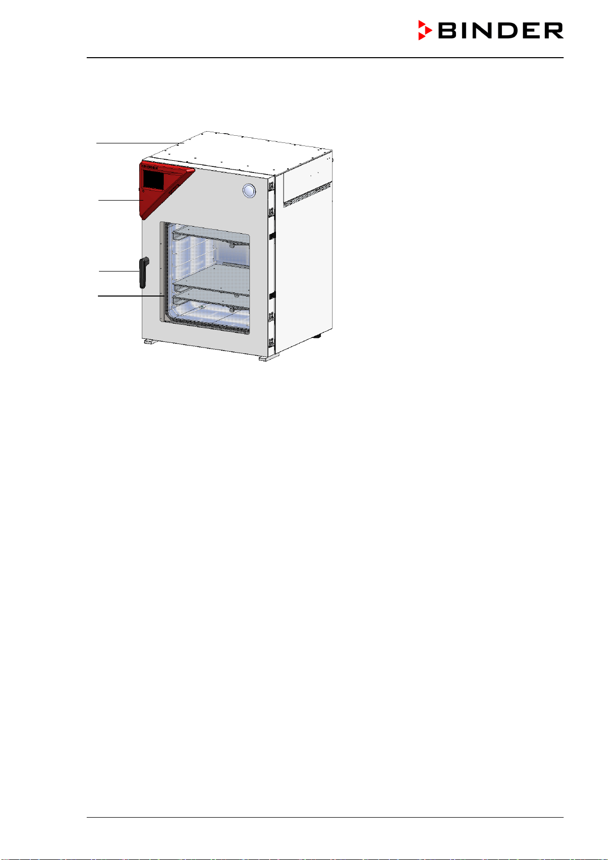
VDL (E3.1) 10/2020 Page 41/196
3.2 Chamber overview
Figure 3: VDL 115 with MB2 controller
(A) Area for electrical equipment
(B) Triangular instrument box (controller housing) with chamber controller
(C) Chamber door
(D) Door handle
(E) Elastic-mounted safety glass window
(A)
(B)
(C)
(D)
(E)
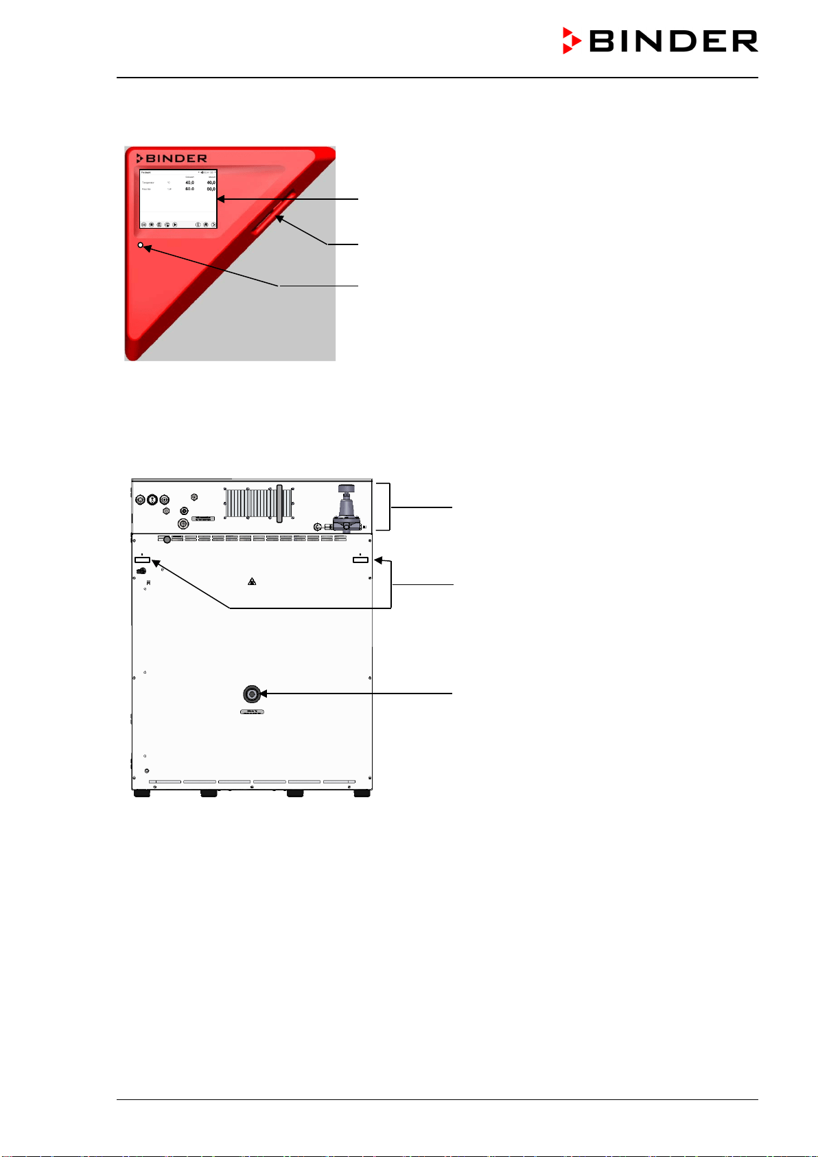
VDL (E3.1) 10/2020 Page 42/196
3.3 Triangular instrument box with MB2 controller
5,7" controller display with touchscreen
USB interface
Pilot lamp
Figure 4: Triangular instrument box (controller housing) with MB2 program controller and USB interface
3.4 Connections on the rear of the chamber
Rear connection panel
Mounting holes for fixing the tilt protection hold-
ers
(12) Measuring connection with small flange
DN16
,
Figure 5: Chamber rear (example: VDL 115)
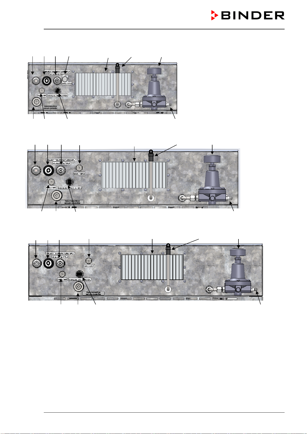
VDL (E3.1) 10/2020 Page 43/196
(1) (2) (3) (5) (8) (11) (9)
VDL 23
(6) (4) (7) (10)
(1) (2) (3) (5) (8) (11) (9)
(4) (6) (7) (10) VDL 56
(1) (2) (3) (5) (8) (11) (9)
VDL 115
(4) (6) (7) (10)
Figure 6: Rear connection panel VDL with options

VDL (E3.1) 10/2020 Page 44/196
(1) Power cable
(2) Connection cable to Ethernet interface for computer communication
(3) 2 connection sockets (3a) and (3b):
(3a) Connection “Object temperature input” (option) for optional object temperature display
(3b) Connection “Analog output” (option) for optional analog outputs for temperature and pressure
(4) Universal connection for inert gas / ambient air “GAS/AIR”, adapter with hose olive ∅ 8 mm / 0.31 in
(5) Additional universal connection for inert gas / ambient air “GAS/AIR 2” (option), adapter with hose
olive ∅ 8 mm / 0.31 in
(6) Vacuum connection with small flange DN16
(7) Plug „Manual ventilation“ for emergency ventilation in case of power failure
(8) Heatsink
(9) Pressure regulator for sweeping / overpressure
(10) Compressed air connection for sweeping / overpressure
(11) Outlet with sweeping plug for compressed air sweeping prior to start-up
3.5 Area classification, information for the zone classification
The operator is to classify the zones. The following areas are identified below:
• Unprotected areas. The spread of an explosive atmosphere to unprotected device parts must be reliably
prevented.
• Areas where, depending on the substances used, explosive atmospheres may occur on a rare and
temporary basis. The creation of a zone outside the defined areas must be reliably prevented.
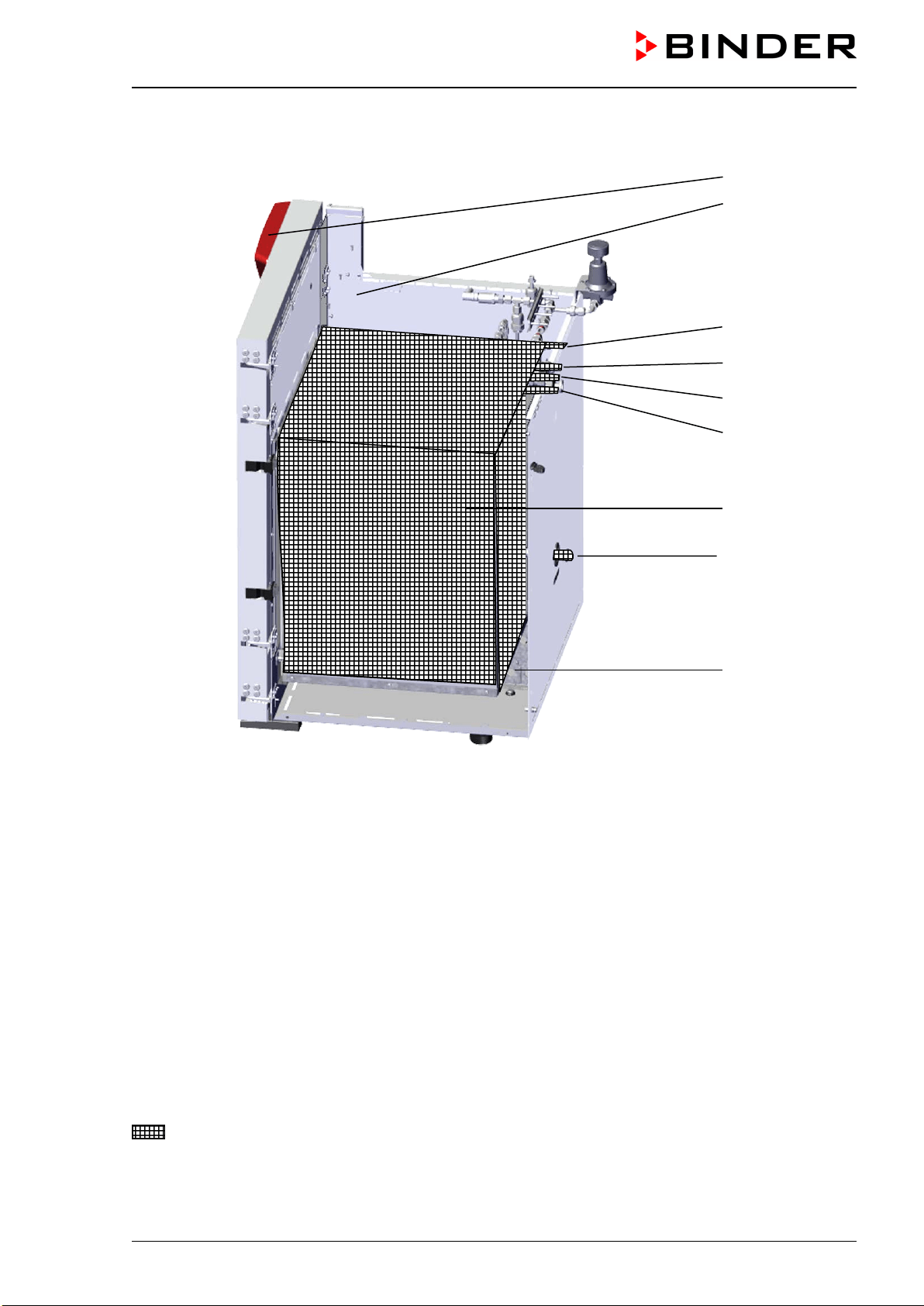
VDL (E3.1) 10/2020 Page 45/196
3.5.1 Area classification inside the chamber
Figure 7: Area classification of the closed chamber
(view without housing, insulation, heater and outer chamber)
(A) Controller housing (swept with compressed air)
(D) Electrical installation area (swept with compressed air)
(H) Inner chamber (usable volume)
(7) Plug “Manual ventilation” for emergency ventilation
(4) Universal connection for inert gas / ambient air “GAS/AIR”
(5) Additional universal connection for inert gas / ambient air “GAS/AIR 2” (option)
(6) Vacuum connection
(12) Measuring connection
(13) Preheating chamber between the inner and outer chamber (swept with compressed air)
Occurrence of an explosive atmosphere:
Occasionally: Inner chamber with tubing / line to the vacuum pump, and connections
(A)
(D)
(5)
(4)
(7)
(6)
(H)
(12)
(13)
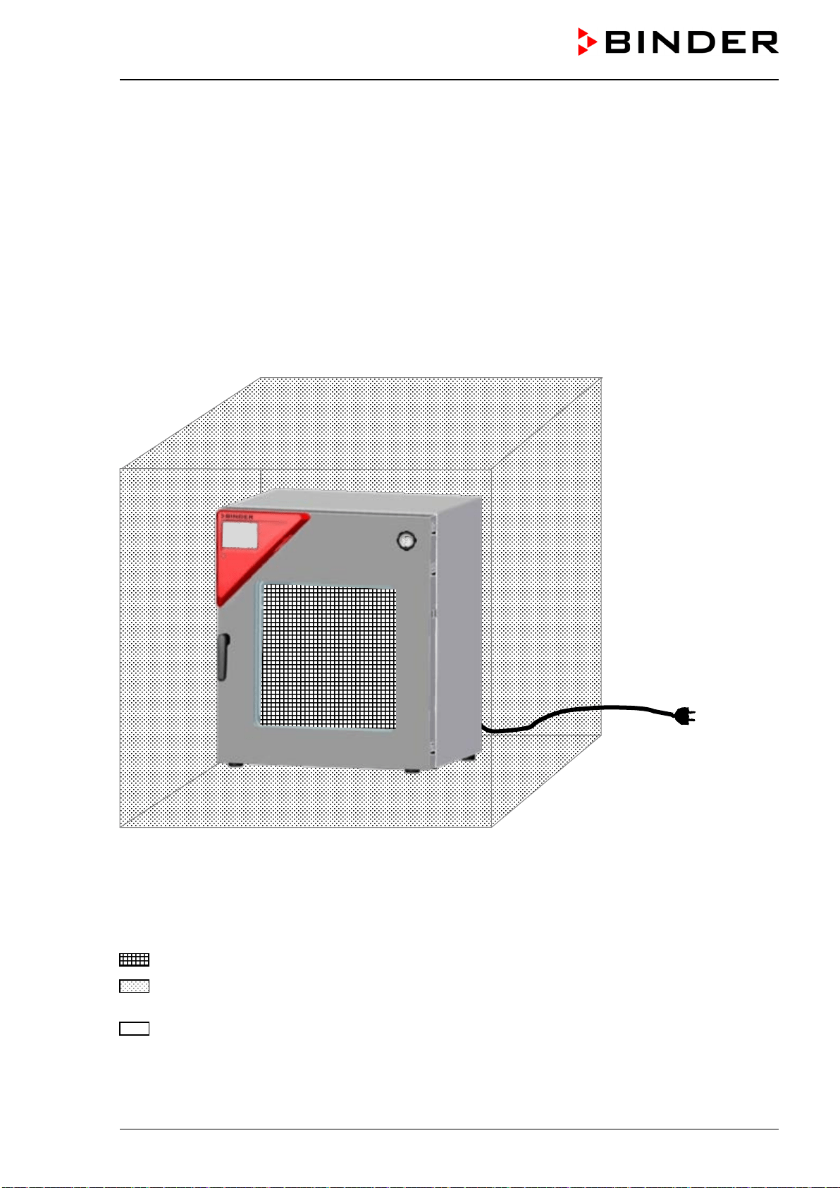
VDL (E3.1) 10/2020 Page 46/196
3.5.2 Area classification in the surroundings of the chamber
The VDL vacuum drying oven, with the exception of the power plug and the plug connection of the optional
analog output, is classified in category 3 in relation to the environment. It may be installed in areas in which
explosive atmospheres may occur on a rare and temporary basis.
The chamber plug (power plug) is unprotected because it must be disconnected in case of an emergency
to completely separate the chamber from the power supply. Therefore, the electrical connection must be
established outside a zone. With optional analog output: The plug connection of the analog output is un-
protected and must therefore be established outside a zone.
Spreading of an explosive atmosphere, which may occur on a rare and temporary basis, to unprotected
areas must be reliably prevented by measures of the operator. In particular, this includes a sufficiently
dimensioned one technical ventilation according to country-specific regulations (TRBS 2152 Part 2 for Ger-
many) and compressed air sweeping).
Figure 8: Area classification in the surroundings of the chamber
(schematic representation, standard device)
Occurrence of an explosive atmosphere:
Occasionally: in the chamber interior with tubing
On a rare and temporary basis: in the ambiance of the chamber, with the exception of the power plug
and the plug connection of the optional analog output
Never (unprotected areas): Connection location of the power plug and the plug connection of the
optional analog output
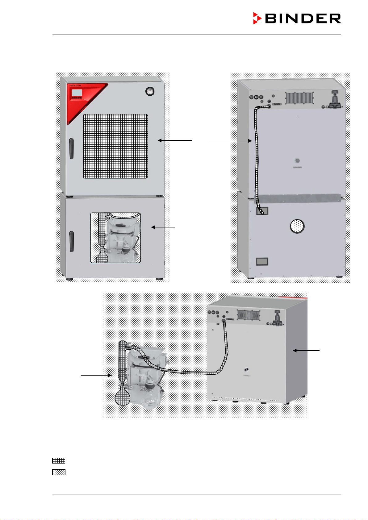
VDL (E3.1) 10/2020 Page 47/196
3.5.3 Area classification in the surroundings of the chamber: extraction lead to the
pump, location of the pump
VDL
Pump module
with pump
(example)
front
rear
Pump
(example)
VDL
(rear)
Figure 9: Area classification in the surroundings of the chamber during operation (example)
Occurrence of an explosive atmosphere:
Occasionally: interior of VDL, line to the vacuum pump, pump
On a rare and temporary basis: surroundings of VDL and pump, interior of the pump module
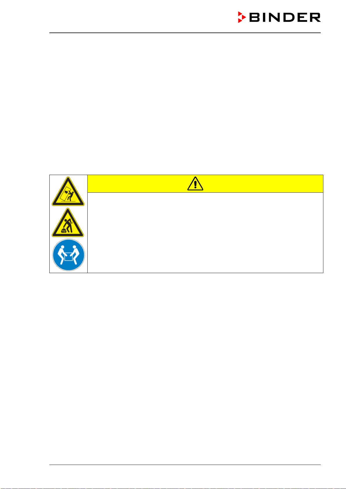
VDL (E3.1) 10/2020 Page 48/196
4. Completeness of delivery, transportation, storage, and installa-
tion
4.1 Unpacking, and checking equipment and completeness of delivery
After unpacking, please check the chamber and its optional accessories, if any, based on the delivery
receipt for completeness and for transportation damage. Inform the carrier immediately if transportation
damage has occurred.
The final tests of the manufacturer may have caused traces of the shelves on the inner surfaces. This has
no impact on the function and performance of the chamber.
Please remove any transportation protection devices and adhesives in/on the chamber and on the doors
and remove the operating manuals and accessory equipment.
Due to different installation heights above sea level, a slight negative pressure in the inner chamber may
prevent the door from being opened. Therefore, after unpacking the chamber, remove the plug “Manual
ventilation” (7) for emergency ventilation from the tube to ensure pressure equalization. After this, thor-
oughly reinstall the plug.
CAUTION
Risk of injury due to sliding or tilting of the chamber in case of improper lifting.
Injuries, damage to the chamber.
∅ Do NOT lift the chamber using the door or the handle.
∅ Do NOT use technical equipment to lift the chambers.
Lift chambers size 23 and 56 from the pallet at the four lower corners with the aid of 4
people.
Lift chambers size 115 from the pallet with the aid of 6 people.
If you need to return the chamber, please use the original packing and observe the guidelines for safe lifting
and transportation (chap. 4.2).
For disposal of the transport packing, see chap. 27.1.
If you ordered the optional pump modulewith a chemical membrane pump, the pump will be delivered in a
separate box and must be fitted into the pump module and connected at the place of installation (see chap.
6.5.3).
Note on second-hand chambers (Ex-Demo-Units):
Second-hand chambers are chambers that were used for a short time for tests or exhibitions. They are
thoroughly tested before resale. BINDER ensures that the chamber is technically sound and will work flaw-
lessly.
Second-hand chambers are marked with a sticker on the chamber door. Please remove the sticker before
commissioning the chamber.
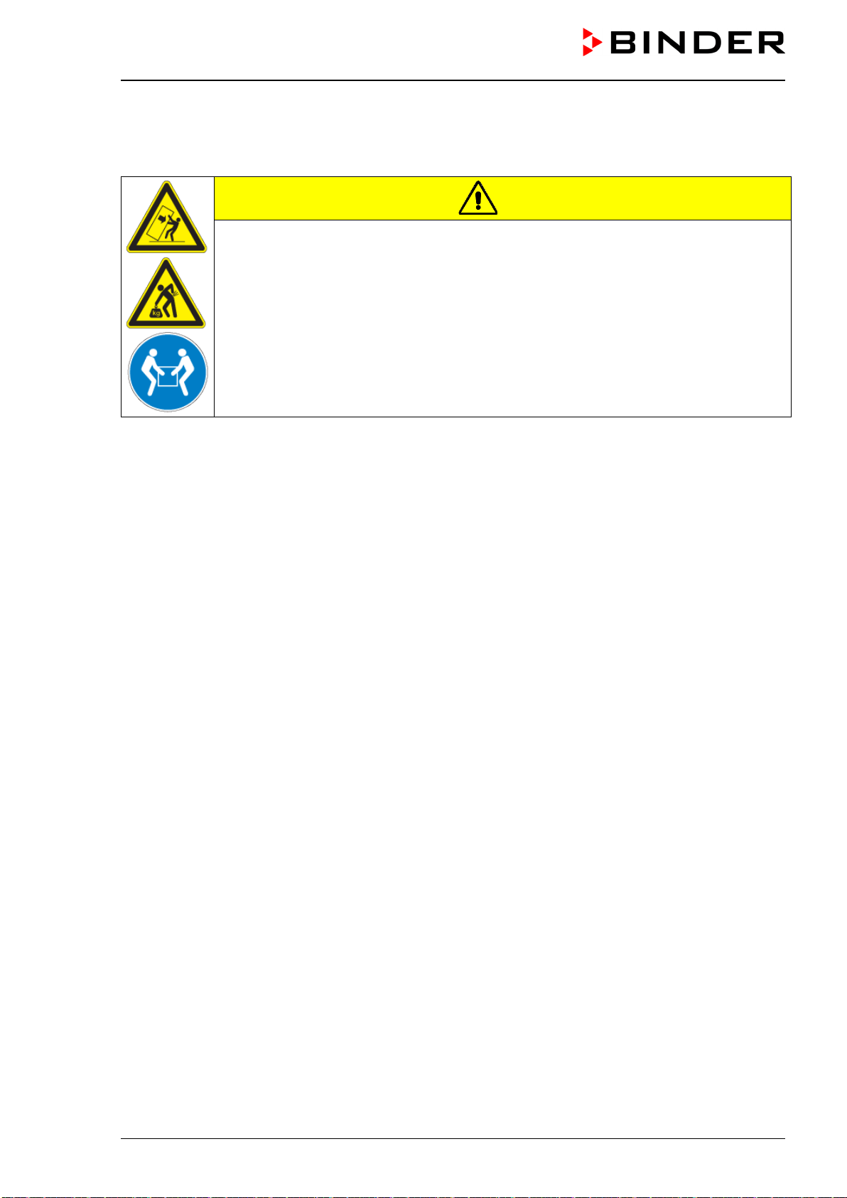
VDL (E3.1) 10/2020 Page 49/196
4.2 Guidelines for safe lifting and transportation
After operation, please observe the guidelines for temporarily decommissioning the chamber (chap. 27.2).
CAUTION
Risk of injury due to sliding or tilting of the chamber in case of improper transport
or by lifting heavy loads.
Injuries, damage to the chamber.
Transport the chamber in its original packaging only.
For moving or shipping, secure the chamber with transport straps.
∅ Do NOT lift or transport the chamber using the door or handle.
Lift chambers size 23 and 56 at the four lower corners with the aid of 4 people.
Lift chambers size 115 with the aid of 6 people.
• Permissible ambient temperature range during transport: -10 °C / 14 °F to +60 °C / 140 °F.
You can order transport packing for moving or shipping purposes from BINDER Service.
4.3 Storage
Intermediate storage of the empty chamber is possible in a closed and dry room. Observe the guidelines
for temporary decommissioning (chap. 27.2).
• Permissible ambient temperature range during storage: -10 °C / 14 °F to +60 °C / 140 °F.
• Permissible ambient humidity: max. 70 % r.h., non-condensing
When after storage in a cold location you transfer the chamber to its warmer installation site, condensation
may form. Before start-up, wait at least one hour until the chamber has attained ambient temperature and
is completely dry.
5. Location of installation and ambient conditions
5.1 General requirements for installation
Set up the vacuum drying oven on a flat, even and non-flammable surface, free from vibration, in a well-
ventilated, dry location and align it using a spirit level or laser. The site of installation must be capable of
supporting the chamber’s weight (see technical data, chap. 28.3). The chambers are designed for setting
up inside a building (indoor use). Provide active extraction (technical ventilation, chap. 5.2.2).
Minimum distances
• Distance between several chambers of the same size: 250 mm / 9.8 in
• Wall distances to rear: 100 mm / 3.9 in
• Lateral wall distances: 70 mm / 2.76 in
• Spacing above and behind the chamber: 100 mm / 3.9 in.
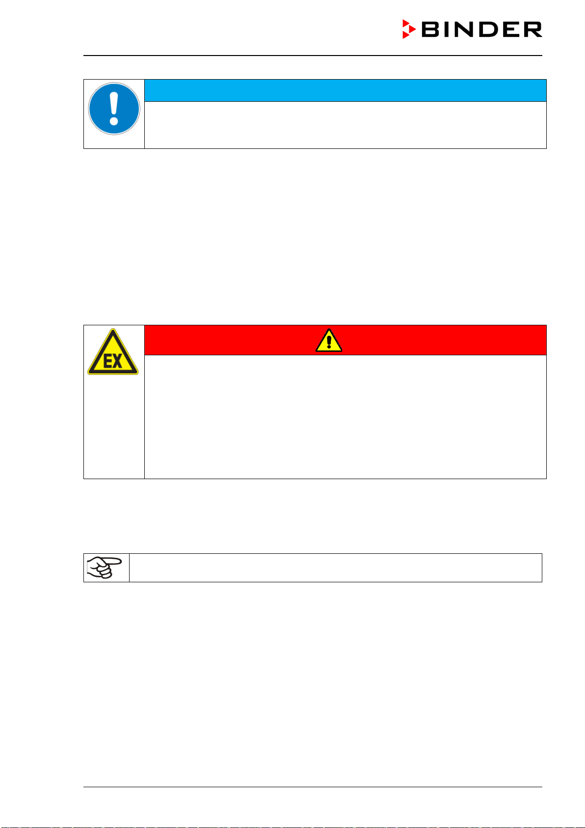
VDL (E3.1) 10/2020 Page 50/196
NOTICE
Danger by stacking.
Damage to the chambers.
∅ Do NOT place vacuum drying ovens on top of each other.
Permissible areas
The VDL vacuum drying oven may be installed in areas in which explosive atmospheres may occur on a
rare and temporary basis. The entire chamber with the exception of the power plug is classified in category
3 in relation to the environment. The chamber plug (power plug) is unprotected, therefore the electrical
connection must be established outside a zone. With optional analog output: The plug connection of the
analog output is unprotected and must therefore be established outside a zone.
VDL vacuum drying ovens are not intended for installation in a Zone 1 or 0. The chamber must not be
installed or operated in an occasionally or continuously / for long periods / frequently potentially explosive
area. Measures must be taken to prevent the spread of explosive atmospheres to unprotected areas.
Spreading of an explosive atmosphere to the unprotected areas must be reliably prevented. Observe the
information on zone classification (chap. 3.5).
Observe the instructions on extraction (technical ventilation, chap. 5.2.2). When installed as intended, there
is no Zone 1 or 0 in the vicinity of the chamber.
DANGER
Explosion hazard by penetration of an explosive atmosphere to unprotected areas.
Serious injury or death from burns and / or explosion pressure.
∅ Do NOT operate the chamber in occasionally or continuously / for long periods / fre-
quently potentially explosive areas. It is not intended for installation in a zone 1 or 0.
Make sure that there are NO combustible dusts in the vicinity of the chamber
Make sure that air-solvent mixtures are NOT occasionally or continuously / for long pe-
riods / frequently in the vicinity of the chamber.
Strictly observe the relevant legal regulations about how to select an appropriate loca-
tion.
The operator is responsible for the correct installation of the pump or other equipment (zone classification).
Sufficient extraction (technical ventilation, chap. 5.2.2) also in the event of an error (e.g. damage / overfilling
the condensate catchpot of the pump, or spilling or dropping containers or material to be loaded with sol-
vents) must be provided.
The operator is responsible to use suitable pumps for pumping from zone 0 or 1.
Follow country-specific regulations for explosion protection.
If you ordered the optional pump module with chemical membrane pump, the vacuum pump will be deliv-
ered in a separate box and must be fitted into the module and connected at the place of installation (chap.
6.5.3).
Electrical connection
To completely separate the chamber from the power supply, you must disconnect the power plug. Install
the chamber in a way that the power plug is easily accessible and can be easily pulled in case of danger.
It is also possible to use a customer’s explosion-protected emergency stop switch or a comparable power
disconnector.
The chamber plug (power plug) is unprotected because it must be disconnected in case of an emergency
to completely separate the chamber from the power supply. therefore, the electrical connection must be
established outside a zone.
VDL (E3.1) 10/2020 Page 51/196
DANGER
Explosion hazard due to sparking when disconnecting an improper electrical con-
nection.
Serious injury or death from burns and / or explosion pressure.
Make sure that the electrical connection is located outside a zone t.
Connect the plug outside the installation area of the VDL and the pump. Take into ac-
count the information on zone classification (chap. 3.5.2)
For the user there is no risk of temporary overvoltages in the sense of EN 61010-1:2010.
5.2 Ventilation and extraction (technical ventilation)
5.2.1 Ventilation for heat removal in normal operation
Install the vacuum drying oven in a well-ventilated place.
NOTICE
Danger of overheating due to lack of ventilation.
Damage to the chamber.
Do NOT set up chambers in non-ventilated recesses.
Ensure sufficient ventilation for dispersal of the heat.
Observe the prescribed minimum distances when installing the chamber (chap. 5.1)
5.2.2 Technical ventilation during chamber operation and when emptying the conden-
sate catchpot of the pump
Provide active extraction at the location of installation. The extraction shall be provided as technical venti-
lation according to country-specific regulations (TRBS 2152 Part 2 for Germany). It must include the entire
installation area of the chamber.
In normal operation, it affects in particular the loading area of the chamber for the spatial limitation and
reduction of any possible explosive atmosphere when loading the chamber. Also in the event of a fault (e.g.
if the material to be loaded or the filled condensate catchpot of the pump falls down), it causes spatial
limitation and reduction of any possible explosive atmosphere.
Extraction must be active during the entire operation of the chamber and when handling the condensate
catchpot of the pump. Extraction must lead into an explosion-proof area.
The operator must ensure active extraction before starting up the chamber. Extraction must be provided
during the entire operation of the chamber as well as when handling the condensate catchpot of the pump.
This ensures that solvent vapors never reach unprotected areas or accumulate in an impermissible manner.
If the technical ventilation fails, the power to the vacuum drying oven must be switched off. It must be
ensured that the device can be switched off by the operator using an explosion-protected device: Pull out
the power plug or operate e.g., a customer’s explosion-protected emergency stop switch.
5.2.3 Air supply (breaking the vacuum) during operation with inert gas
When operating the VDL safety vacuum drying oven with inert gas, correctly follow the technical ventilation
measures, as described in the DGUV guidelines 213-850 on safe working in laboratories, issued by the
employers’ liability insurance association (for Germany).
VDL (E3.1) 10/2020 Page 52/196
5.3 Equipotential bonding
The accessible installation and operating surface of the chamber must be electrically conductive. The ac-
cessible installation and operating surface of the chamber must be electrically conductive. This installation
and operating surface must be connected to the vacuum drying oven and other equipment (e.g. Pump
module, vacuum pump) according to the grounding concept. Provide cyclic measurements.
For the grounding concept see chap. 6.8.
When inserting or loading objects into the loading area , note that there may be a potential equalization.
The personal protective equipment (PPE) of the operating personnel must be implemented ESD protected.
5.4 Ambient conditions
• Permissible ambient temperature during operation: +18 °C / 64 °F to +32 °C / 90 °F.
The ambient temperature should not be substantially higher than the indicated ambient tem-
perature of +22 °C +/- 3 °C / 71.6 °F +/-5.4 °F to which the specified technical data relate. De-
viations from the indicated data are possible for other ambient conditions.
• Permissible ambient humidity: 70 % r.h. max., non-condensing.
• Installation height: max. 2000 m / 6562 ft above sea level.
The maximum permissible ambient temperature of the vacuum pumps delivered by BINDER is 40 °C / 104
°F.
5.5 Compressed air supply for sweeping the area for electrical equipment, the
preheating chamber, and the controller housing
Before commissioning the chamber, connect the vacuum drying oven to the compressed air supply (chap.
6.3).
The compressed air supply line provided by the operator must be equipped with active monitoring of the
defined inlet pressure (2 bar), which clearly indicates a drop and increase in the inlet pressure outside the
permissible tolerance of ± 0.2 bar.
5.6 Fire extinguisher
During operation a fire extinguisher must be available.
5.7 Lightning protection device
The building in which the vacuum drying oven is installed must have a lightning protection system. All
internal connections in the operator's building must contain lightning protection in accordance with EN/IEC
62305-3.
Lightning protection measures must be taken in order to prevent melting and spraying effects. The opera-
tor’s zone classification shall be used to plan lightning protection measures. The lightning discharge paths
must be designed so that heat or ignitable / spray sparks cannot become the ignition source for an explosive
atmosphere.
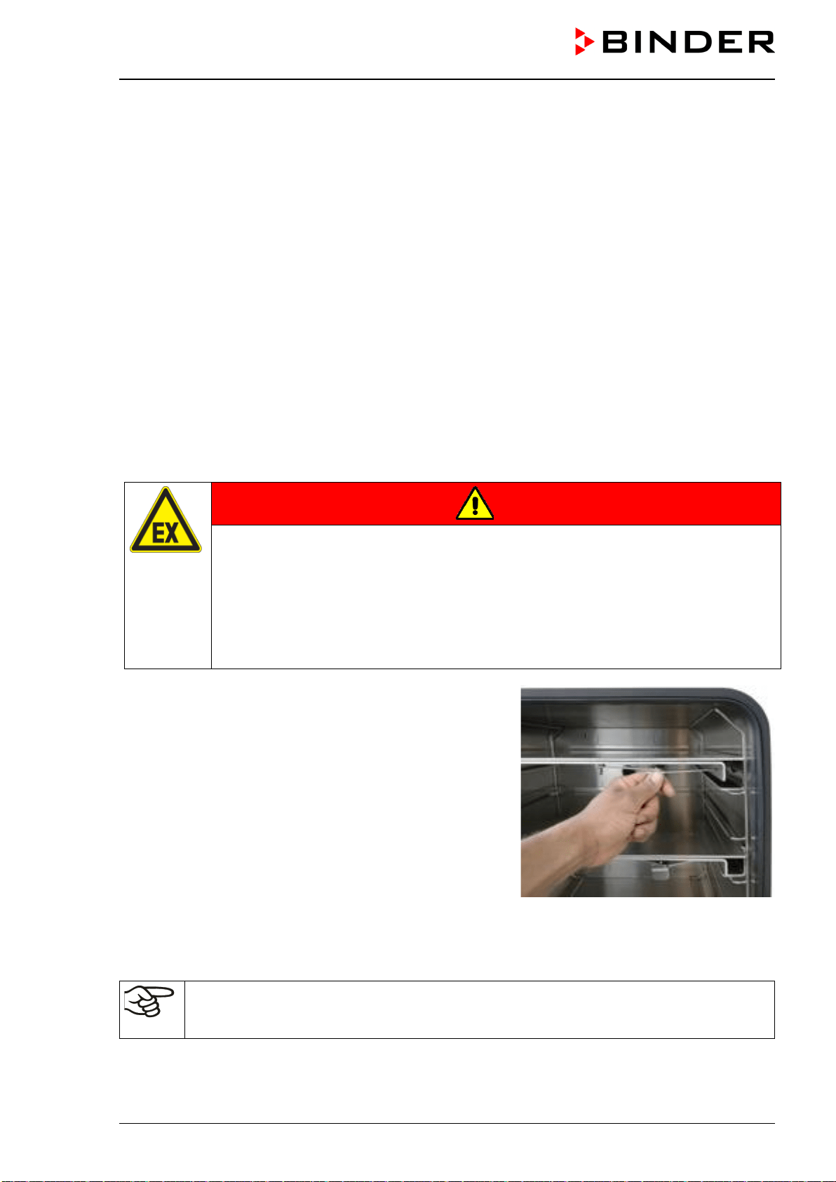
VDL (E3.1) 10/2020 Page 53/196
6. Installation and connections
The chambers may only be installed, connected, and commissioned by specialist personnel. Specialist
personnel must have knowledge of the types of ignition protection and regulations and ordinances for
equipment used in hazardous areas (Ex areas).
Verify whether the Ex classification (Ex classification label on the type plate) is suitable for the application.
6.1 Vacuum expansion racks and rack holders
Vacuum expansion racks and rack holders can easily be removed from the chamber. This offers the
advantage of an inner chamber with smooth walls, which is easy to clean.
Inserting or loosening an expansion rack and inserting or removing the rack holders may only be
done in the absence of solvents and under extraction (technical ventilation).
The rack holders can only be removed from the chamber after removing the expansion racks.
Rack holder installation: Align the rack holders to the cams in the bottom of the inner chamber and insert
them.
Prior to insertion check the expansion racks and rack holders for corrosion . If corrosion is detected, the
affected element must not be used.
DANGER
Explosion hazard due to creation of mechanical sparks in an explosive atmosphere.
Serious injury or death from burns and / or explosion pressure.
Insert or remove the expansion racks and rack holders only in the absence of solvent.
Insert or remove the expansion racks and rack holders only with active extraction
(technical ventilation).
Prior to inserting the expansion racks and rack holders, check them for corrosion.
∅ Do NOT use corroded expansion racks and rack holders.
The vacuum expansion racks made of aluminum (also option-
ally available in stainless steel) allow low-loss heat transfer to
the material. The strong tension causes the racks to fit tightly
against the interior wall and their large-surface contact area
ensures rapid and effective heat transfer.
The removable rack holders allow for easy positioning.
You can remove the expansion racks for easy cleaning. Do
not remove them too often in order to prevent wear.
Figure 10: Operating the expansion racks
• Pushing the locking lever: The expansion rack is released and can be removed.
• Pulling the locking lever: The expansion rack is pressed against the inner chamber walls.
Remove or insert the vacuum expansion racks only when the chamber is empty and has
cooled down. NO explosive atmosphere must be present. Active extraction (technical ventila-
tion) is mandatory.
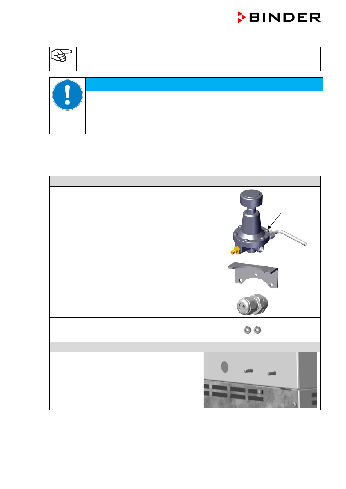
VDL (E3.1) 10/2020 Page 54/196
Following each new tightening of an expansion rack, check that the lateral parts of the rack fit
closely over their whole surface to the inner chamber wall. This is necessary in order to en-
sure the specified temperature exactitude.
NOTICE
Risk of invalid calibration due to modified heat transmission when changing be-
tween aluminum and stainless-steel racks.
Undefined heating behavior.
∅ Do NOT change between aluminum and stainless-steel racks
∅ Use the supplied expansion racks only.
6.2 Mounting the pressure regulator
The pressure regulator is included with the chamber and must be mounted on the chamber rear
Accessory pack for mounting the pressure regulator
(a) pressure regulator
(b) tube
(c) 6 screws
(d) brass nozzle for compressed air connection
(e) bracket
(f) cable connector
(g) 2 nuts
for the bolts with thread on the chamber rear
Connections on the chamber rear as supplied
(h) hole for the cable connection
(i) 2 bolts with thread
(a)
(b)
(d)
(c)
(e)
(f)
(g)
(h)
(i)
(i)
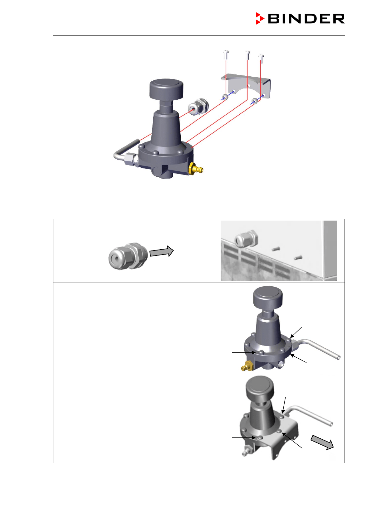
VDL (E3.1) 10/2020 Page 55/196
Figure 11: Mounting the pressure regulator on the chamber rear
Proceed in the following order:
• Insert the cable connector (f) into the existing hole (h)
in the rear wall until it clicks into place
• Unscrew the three screws (c) pointing to the chamber
from the pressure regulator
• Fix the three screws (c) together with the bracket l (e)
on the pressure regulator
(f)
(c)
(c)
(c)
(c)
(c)
(c)
(e)
(b)
(f)
(c)
(e)
(d)
(b)
(a)
(g)
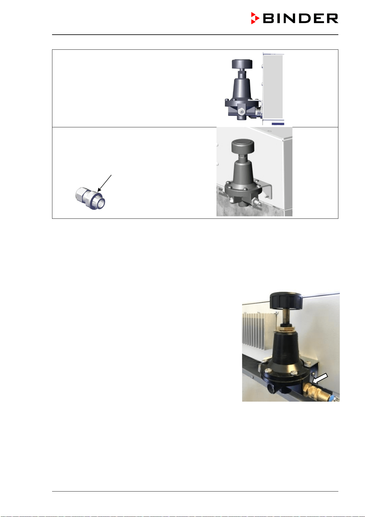
VDL (E3.1) 10/2020 Page 56/196
Fixation on the chamber rear:
• Guide the tube (b) through the cable connector (f) and
push the bracket (e) with the pressure regulator with
its lower two holes onto the two bolts (i) on the rear of
the chamber
• Screw the two nuts (g) onto the bolts (i) and tighten
them
• Tighten the nut of the cable connector (f) which points
to the chamber clockwise with a tool so that it can no
longer be loosened by hand
6.3 Connecting compressed air supply for sweeping the area for electrical
equipment, the preheating chamber, and the controller housing
The compressed air flows through the area for electrical equipment, the preheating chamber, and the con-
troller housing, which prevents a possible concentration of a solvent-containing atmosphere in the presence
of live electrical components and the hot heater surface.
Use only dry compressed air.
In order to avoid that any oil coming from the compressed-air piping
enters the vacuum drying oven, the compressor of the compressed
air system must be equipped with an oil separator, or the com-
pressed air system must be constructed oil-free.
Connection:
Before commissioning, the pressure regulator on the chamber rear
must be connected to a compressed air line (compressed air net-
work).
Connection: Plug connector for DL quick coupling NW5
An inlet pressure of 2 bar must be provided for the compressed air
sweeping. The compressed air supply line provided by the operator
must be equipped with monitoring which clearly indicates a drop
and increase in the inlet pressure outside the permissible tolerance
of ± 0.2 bar.
Figure 12: Compressed air connec-
tion on the pressure regulator
If solvent-containing air penetrates the electrical areas of the chamber or the preheating chamber, explo-
sions may result.
(f)
(g)
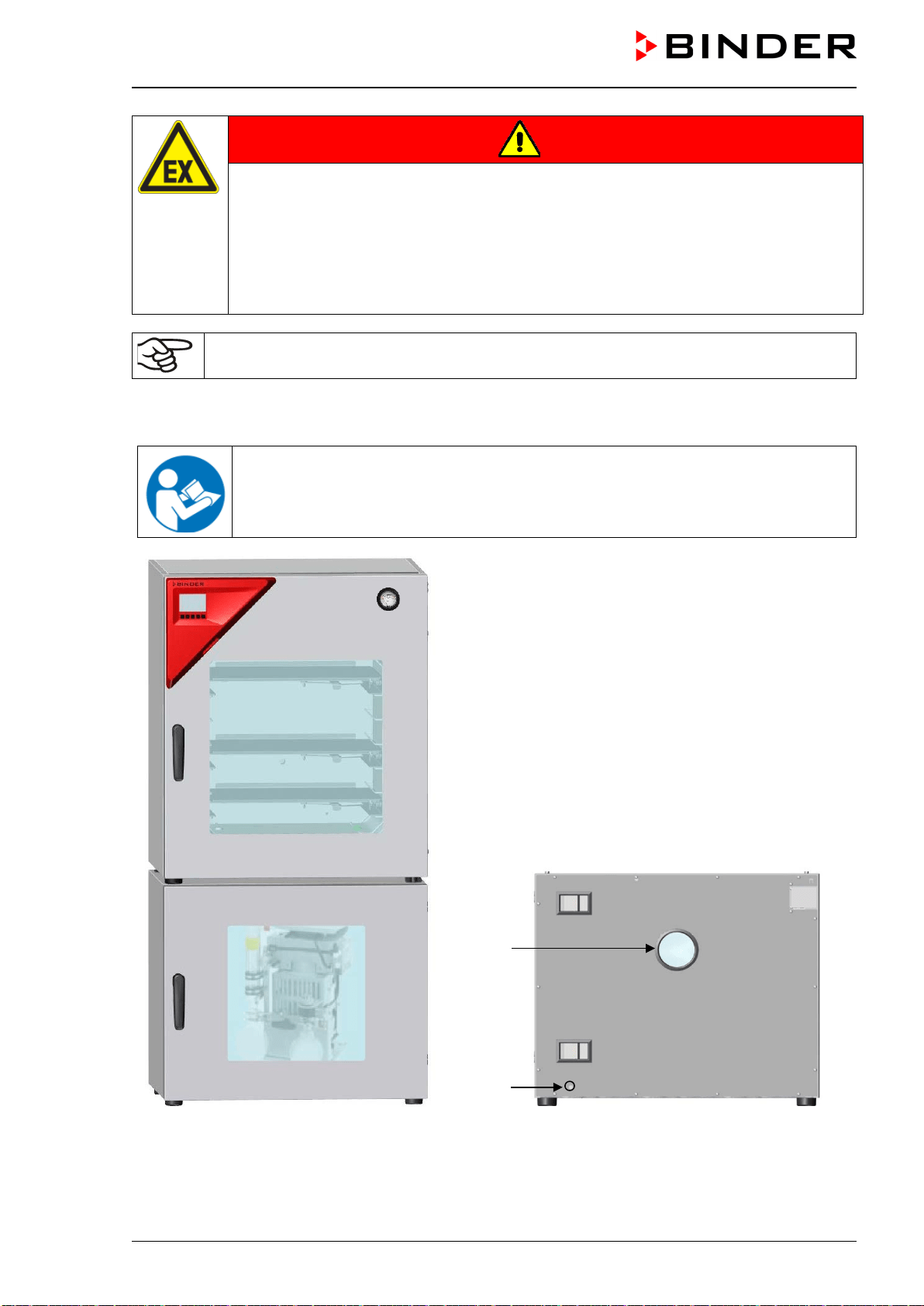
VDL (E3.1) 10/2020 Page 57/196
DANGER
Explosion hazard by solvent-containing air penetrating the electrical area of the
chamber or the preheating chamber.
Serious injury or death from burns and / or explosion pressure.
∅ Make sure that the air for the compressed air supply is NOT taken from explosive at-
mospheres.
∅ Ensure that the compressed air supply line provided by the operator is equipped with
active monitoring of the defined inlet pressure.
Do NOT start the VDL vacuum drying oven when the chamber is not connected to the com-
pressed air supply, or if the specified overpressure is not reached.
6.4 Pump module (option)
The mounting instructions Art. no. 7001-0137 supplied with the pump moduledescribe
how to mount the vacuum drying oven onto the pump module and installing the suction
line into the pump module.
Figure 13: VDL mounted on pump module
(example size 115)
Figure 14: Pump module, rear view
(example size 115)
(14) Connection to extraction
(15) Fixation screw fitting for grounding
(15)
(14)
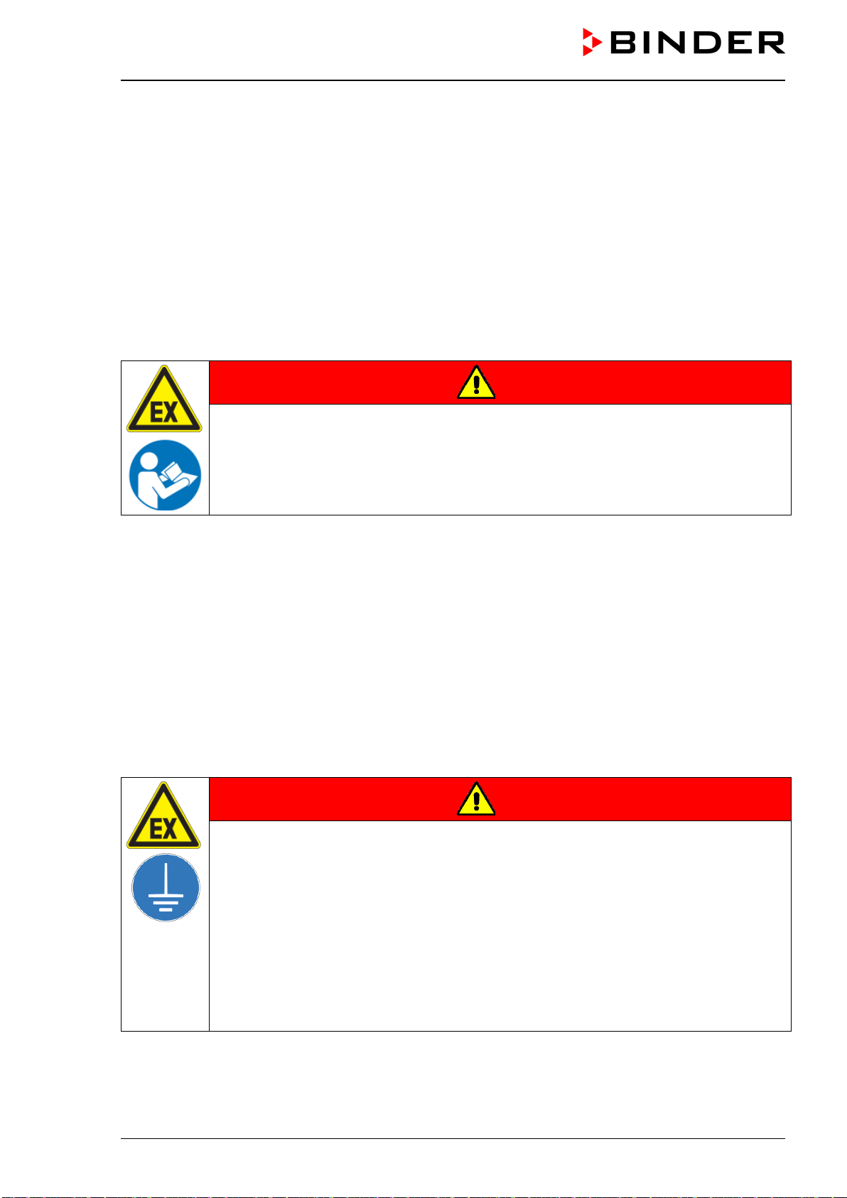
VDL (E3.1) 10/2020 Page 58/196
The following steps 6.4.1 to 6.4.3 are described in detail in the mounting instructions Art. no. 7001-0137.
Please proceed accordingly.
6.4.1 Mounting
• Placing the vacuum drying oven on the vacuum module
• Mounting the connecting plate
• Installing the suction line: Hose connection at the VDL vacuum connection (11) and fixing the hose at
the housing rear
• Installing the condensate collecting tray
Inappropriate execution of the connections can lead to the risk of explosion.
DANGER
Danger of ignition and explosion by inappropriate installation.
Serious injury or death from burns and / or explosion pressure.
It is obligatory to follow the instructions of the mounting instructions Art. no. 7001-0137
regarding correct installation.
Observe the safety advice as in chap. 1.7.3.
6.4.2 Achieving equipotential bonding acc. to the grounding plan
• The conductive connection between the VDL and the pump module is established by mounting the
connecting plate.
• To establish a conductive connection between the vacuum pump and the pump module a grounding
cable is supplied, which is already fixed at the pump module. It will be connected to the pump.
• To establish a conductive connection between the condensate collecting tray and the pump module the
front edge of the tray is screwed on the front of the vacuum module
• To establish a conductive connection between the pump module and the conductive surface of the
installation site a grounding cable is supplied with the pump module. It is screwed on the fixation screw
fitting for grounding of the pump module and connected to the conductive surface of the installation site.
DANGER
Explosion hazard due to electric sparking due to missing or improperly imple-
mented equipotential bonding.
Serious injury or death from burns and / or explosion pressure.
Connect all elements in the installation and loading area (VDL / pump module / pump)
with the conductive surface and/or with each other. Proceed according to the grounding
plan in chap. 6.8.
For installation of the pump module proceed acc. to the mounting instructions of the
pump module (Art. no. 7001-0137).
Before commissioning, measure the equipotential bonding after first setting up the VDL
and implementing all described measures for establishing the equipotential bonding
Provide cyclic measurements of the equipotential bonding.
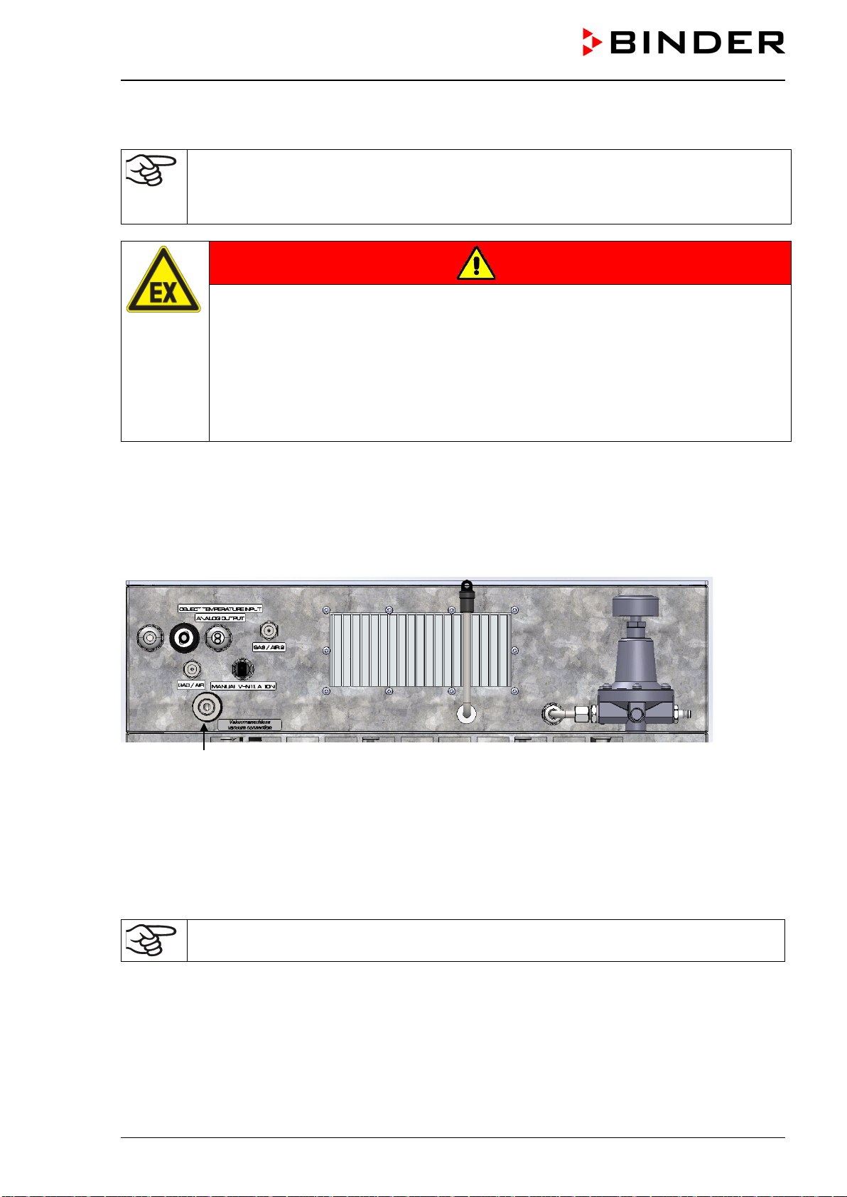
VDL (E3.1) 10/2020 Page 59/196
6.4.3 Connection of an extraction system at the pump module
Avoid the solvent accumulation in the pump module as this would cause the pump module to
become an occasionally or continuously / for long periods / frequently potentially explosive
area (Zone 0 or 1). The VDL vacuum drying oven located on top of the module is constructed
in device category 3 in regards to its surroundings.
DANGER
Explosion hazard due to the spread of an explosive atmosphere to unprotected
chamber parts and ignition due to electric sparking or hot surfaces
Serious injury or death from burns and / or explosion pressure.
Provide active extraction (technical ventilation according to country-specific regulations
– TRBS 2152 Part 2 for Germany) prior to commissioning the chamber.
Extraction must include the entire installation area of the vacuum drying oven and pump
module.
Connect an extraction system to the provided port on the rear of the pump module.
6.5 Vacuum connection
Connect the vacuum drying oven to a vacuum pumpor to a domestic vacuum system. For this purpose, the
vacuum connection (6) with small flange DN16 must be connected to the back of the chamber at the top
with the vacuum pump or domestic vacuum system via a vacuum suction hose or a fixed vacuum pipe.
(6)
Figure 15: Position of the Vacuum connection (6) on the chamber rear (example size 56)
When using a vacuum suction hose BINDER recommends the connection kit for the VP4 pump from
BINDER (chap. 6.5.5). The optional pump module (chap.) provides an appropriate hose port on the rear.
6.5.1 Instructions for using vacuum pumps
Vacuum pumps with a suction capacity of 1-30 m³/h are suitable for the VDL vacuum drying
oven.
For use of vacuum pumps in the European Union, note the following points:
• Units that will be operated in potentially explosive areas have to meet the requirements of ATEX Di-
rective 2014/34/EU. Observe the safety instructions in chap. 1.7.
VDL (E3.1) 10/2020 Page 60/196
• If combustible solvent will be introduced into the inner chamber, the vacuum pump must be constructed
in a suitable explosion-proof manner. The mixtures extracted from the drying chamber must be carried
away making sure that there is no danger by ignition of these atmospheres.
Follow the safety instructions of the pump manufacturer.
In the event of an error, sparking in the pump motor or the switching elements, electrostatic discharges, as
well as hot pump parts can ignite solvent vapors. Minimize this risk by using an ATEX Directive 2014/34/EU
compliant vacuum pump suitable for suction from Zone 0 or 1 and, if appropriate, from the zone of its
installation site.
DANGER
Explosion hazard caused by emerging solvent vapors, which can ignite due to
sparking in the pump motor or the switching elements, electrostatic discharges and
hot pump parts.
Serious injury or death from burns and / or explosion pressure.
Use only suitable, explosion-proof pumps
Operate the pump in a stationary position and secure it so it is immobile.
Make sure that the suction line to the vacuum connection (6) is installed fix and conduc-
tive.
Avoid that the exhaust pipe conducts ignitable solvent concentrations by sufficient sol-
vent condensation e.g., in an exhaust waste vapor condenser
Make sure that the exhaust pipe is installed fix and conductive in case it may still con-
duct ignitable solvent concentrations.
Ensure equipotential bonding between the pump housing and the housing of the VDL
vacuum drying oven via the connected equipment grounding conductors of both units.
When using ATEX Directive 2014/34/EU non-compliant pumps:
Provide a current-dependent, delayed protective device for the pump (for the triggering
time of this protective device, see the manufacturer’s specifications). The protective and
monitoring device must not be able to independently turn on again or be released.
Install the switch gear box outside the hazardous area or provide it with explosion pro-
tection.
The ATEX Directive 2014/34/EU compliant pumps offered by BINDER provide an integral
protective device and an integral explosion proof switch.
Make sure that the vacuum source is designed for a gas inlet temperature corresponding to
the used drying temperature, or take appropriate measures to cool down the extracted vapor
before it enters into the vacuum source.
Observe the permissible gas inlet temperature of the vacuum pump in use. Do NOT exceed this
temperature. If the gas inlet temperature is too high and then becomes even warmer by compression in the
pump, the resulting temperature (of the gas-solvent mixture inside the pump) could exceed the solvent’s
temperature class and auto-ignition temperature .
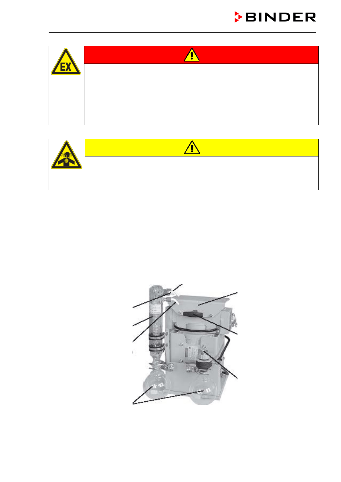
VDL (E3.1) 10/2020 Page 61/196
DANGER
Fire and explosion hazard by exceeding the auto-ignition temperature of the solvent
with a too high gas inlet temperature.
Damage to the vacuum pump. Serious injury or death from burns and / or explosion
pressure.
Do NOT exceed the maximum gas inlet temperature of the pump. Adjust the tempera-
ture set-point accordingly.
With a higher set-point temperature, take appropriate measures to cool down the ex-
tracted vapor before it enters into the vacuum pump.
Extracted vapors can have a health damaging and/or corrosive effect on the chamber and pump.
CAUTION
Health hazard due to release of extracted vapors.
Corrosion of oven and pump. Damage to health.
Conduct the extracted vapors e.g., into a fume extractor facility. Connect a suitable
hose to the vacuum pump outlet that may be located in the pump module.
To avoid condensation inside the chamber and in the suction system, select an appropriate vacuum source
to ensure its sufficient performance in relation to the released amount of steam. Coordinate drying temper-
ature, suction performance of the vacuum source and the amount of loading material.
6.5.2 Vacuum pump VP4 (option)
. The VP4 chemical membrane pump is located in a separate transport packaging. It is delivered as com-
plete pump stand with a separator and an exhaust waste vapor condenser.
We recommend to install the vacuum pump in the optional pump module. For installation of the pump,
please refer to chap. 6.5.3.
Outlet port (gas!)
Exhaust waste vapor
condenser
Cooling water inlet (hose
nozzle 6 mm / 0.23 in)
Round bottom flask as con-
densate catchpot
Cooling water outlet (hose nozzle 6 mm)
Guard plate
Carrying handle
Inlet (vacuum connection)
Figure 16: Vacuum pump VP 4 (MZ2C EX)
VDL (E3.1) 10/2020 Page 62/196
Defining the zone of the installation site of the vacuum pump (Directive 1999/92/EC)
If the pump module is defined as Zone 1, the operating chamber of the vacuum pump must be swept with
inert gas. A flow of at least 1 liter per minute (without pressure) is needed. For Zone 2 or without any zone
sweeping with inert gas is not required. In addition to sweeping with inert gas, in case of condensing media,
you can connect a gas ballast in order to avoid condensation.
The ATEX Directive 2014/34/EU compliant vacuum pump offered by BINDER is designed for a gas
inlet temperature of 40 °C / 104 °F max. Do NOT exceed this temperature. If the gas inlet temperature is
too high and then becomes even warmer by compression in the pump, the resulting temperature (of the
gas-solvent mixture inside the pump) could exceed the solvent’s temperature class and auto-ignition tem-
perature.
DANGER
Fire and explosion hazard due to exceeding the solvent’s auto-ignition temperature
by exceeding the gas inlet temperature.
Damage to the vacuum pump. Serious injury or death from burns and / or explosion
pressure.
Do NOT exceed the set-point temperature 40 °C / 104 °F.
With a set-point temperature above 40 °C / 104 °F, take appropriate measures to cool
down the sucked-in gas before its entry to the vacuum pump.
The maximum permissible ambient temperature of the vacuum pumps supplied by BINDER is 40 °C /
104 °F.
6.5.3 Installation of the vacuum pump VP4 in the pump module (option)
Avoid the solvent accumulation in the pump module as this would cause the pump module to
become an occasionally or continuously / for long periods / frequently potentially explosive
area (Zone 0 or 1). The VDL vacuum drying oven located on top of the module is constructed
in device category 3 in regards to its surroundings.
Installation of the supplied vacuum pump
• The vacuum drying oven is mounted onto the pump module as described in the mounting instructions
Art. No. 7001-0137.
• The suction line to the pump module is installed as described in the mounting instructions Art. No. 7001-
0137. Connect the vacuum connection (6) (small flange DN 16) on the back of the chamber to a vacuum
suction lead. When using a vacuum tube BINDER recommends the BINDER connection kit for VP4
(chap. 6.5.5). The optional pump module has a corresponding hose outlet on its rear.
• When the pump is removed from the original packaging, place it in the pump module.
• Connect the grounding elements as described in the mounting instructions Art. no. 7001-0137.
• Connect the pre-installed suction line to the vacuum pump inlet at the suction-side small flange connec-
tion located at the top of the condensate catchpot).
• Connect a conduit that is suitable for removing the extracted vapors from the pump module, onto the
pressure-side connection of the vacuum pump (hose olive on the top-back of the emission condenser).
• Guide the end of the conduit into an exhaust air system, which is explosion-proof constructed in consid-
eration of any possible residual solvent contents. The operator must check if an explosive atmosphere
may be present at the pump exit or at the exhaust waste vapor condenser. For this purpose, use a
calculation of the solvent’s partial pressure at the set-up coolant temperature of the exhaust waste vapor
condenser and compare it to the explosion limits of the pumped solvent. The exhaust solvent concen-
tration should be minimized by selecting the most appropriate condensation temperature for the solvent
at the refrigeration plant that can be connected to the exhaust waste vapor condenser.
VDL (E3.1) 10/2020 Page 63/196
The pumped-out gases at the pump exit or the exhaust waste vapor condenser must be removed in a
controlled manner and according to applicable security regulations. If there is any possibility that an
explosive mixture could still exist, the exhaust must be removed through antistatic conduits and disposed
of according to the valid regulations of explosion protection.
• Establish the electrical connection at the pump’s connector box. This must be carried out according to
the original user manual of the pump manufacturer and to EN 60079-0, observing the zone that has
been defined by the operator for the installation site of the pump. Equipotential bonding between the
pump housing and the housing of the vacuum drying oven must be assured by the connected equipment
grounding conductors of both units.
Inappropriate execution of the pump connection can lead to the risk of explosion.
DANGER
Danger of ignition and explosion by inappropriate pump connection .
Serious injury or death from burns and / or explosion pressure.
It is obligatory to follow the instructions of the pump manufacturer regarding correct
connection and commissioning.
Observe the safety advice as in chap. 1.7.
Extracted vapors or the occasionally used inert gas can endanger health and / or have a corrosive effect
on the oven and pump.
WARNING
Danger of damage to health by release of extracted vapors.
Corrosion on the chamber and the pump. Damage to health.
Remove the extracted vapors and/or inert gas via a suitable conduit from the pump
module into e.g., a fume extractor facility.
Directly connect the conduit to the corresponding pump outlets.
You can connect a laboratory cooling system to the emission condenser of the vacuum pump
VP4.
To operate the chemical membrane pumps VP4 (MZ2C EX) please refer to the enclosed
pump manufacturer's operating manual.
Confirm that the vacuum source is designed for a gas inlet temperature corresponding to the
used drying temperature, or take appropriate measures to cool down the extracted vapor be-
fore its entry into the vacuum source.
The ATEX Directive 2014/34/EU compliant vacuum pump offered by BINDER is designed for a gas
inlet temperature of 40 °C / 104 °F max. Do NOT exceed this temperature. If the gas inlet temperature is
too high and then becomes even warmer by compression in the pump, the resulting temperature (of the
gas-solvent mixture inside the pump) could exceed the solvent’s temperature class and auto-ignition tem-
perature .
The maximum permissible ambient temperature of the vacuum pump supplied by BINDER is 40 °C / 104 °F.
VDL (E3.1) 10/2020 Page 64/196
6.5.4 Note on the use of a flame arrester
A flame arrester is not mandatory for VDL applications (TRBS 2152-4:2012). A pump designed for Zone 1
is equipped with a temperature sensor on the bearing which, in the event of a fault, causes the pump to
shut down immediately.
In general: In case of a risk of ignition before or after the vacuum pump, the operator must provide suitable
flame arresters in accordance with EN 12874. The suitability (chemical resistance, sufficient flow and safety
against clogging) must be ensured before commissioning.
6.5.5 ATEX connection kit for vacuum pump VP4 (option)
Connection kit for VP4 (Art. no. 8012-0621) consists of:
• Straining ring DN10/16 (3 pc.)
• Universal centering ring DN10/16 (3 pc.)
• Transition piece, adapter DN 16-10/8 (2 pc.)
• Vacuum hose 10/8, 2 m / 78.7 in
• Union nut M14 (2 pc.)
• Elbow DN 10/10
For mounting the VDL connection kit for VP4, please refer to the mounting instructions Art.
no. 7001-0152 supplied with the connection kit.
6.6 Connecting inert gas supply
When operating the VDL vacuum drying oven with inert gas, correctly follow the technical ventilation
measures, as described in the DGUV guidelines 213-850 on safe working in laboratories, issued by the
employers’ liability insurance association (for Germany
When operating with inert gas, the chamber is supplied with an oxygen displacing gas, e.g., N
2
. Inert gases
in high concentrations are hazardous to health. They are colorless and almost odorless and therefore prac-
tically imperceptible. Inhalation of inert gases can cause drowsiness up to respiratory arrest. When the O
2
content of the air decreases below 18%, there is risk of death from lack of oxygen. Any gas that might
escape has to be led out via good room ventilation or a suitable exhaust system.
DANGER
Risk of suffocation by inert gas in a high concentration.
Death by suffocation.
∅ Do NOT set up chambers in non-ventilated recesses.
Ensure that technical ventilation measures are activated.
Respect the relevant regulations for handling inert gases.
When decommissioning the vacuum drying oven, turn off the inert gas supply.
Connect the inert gas supply to the inert gas connection (adapter with hose olive diameter 8 mm / 0.31 in)
via a pressure reducer. Screw the enclosed adapter with hose olive on the thread (4) at the chamber rear.
Set the pressure reducer to a pressure slightly above ambient pressure. Ensure that the pressure reducer
will certainly open. Do not alter this setting in order to avoid perturbation inside the oven and release of big
quantities of inert gas after flooding the VDL.
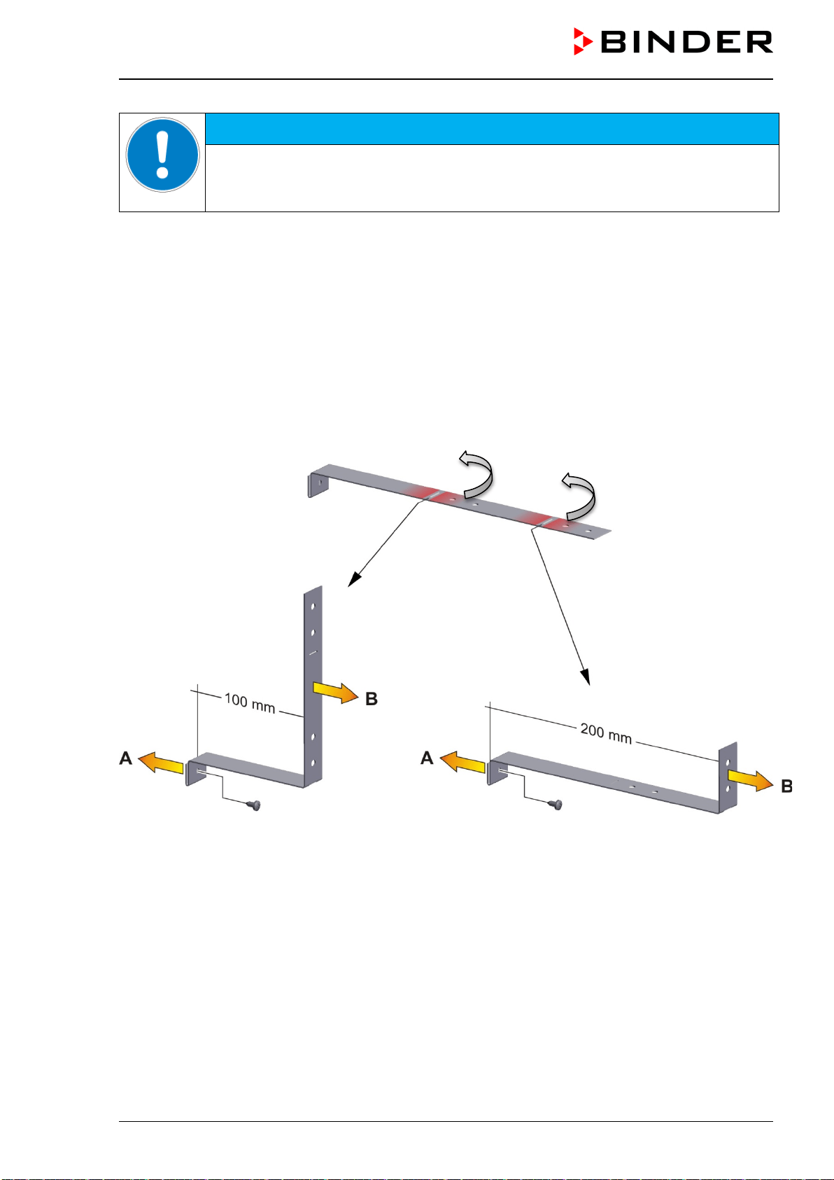
VDL (E3.1) 10/2020 Page 65/196
NOTICE
Overpressure in the inner chamber.
Perturbation of the load.
∅ DO NOT change the setting of the atmospheric pressure.
6.7 Mounting the tilt protection holders
For chambers placed on the optional pump module it is recommended to install the supplied tilt protection.
Scope of delivery of tilt protection kit (Art.no. 8009-0870):
• 2 screws
• 2 tilt protection holders
Preparing the tilt protection holders
• Depending on the desired wall distance, you can bend the tilt protection holders accordingly.
Figure 17: Variable length of the tilt protection holder depending on the bend
Installation on the chamber
• Plug the two tilt protection holders each with the tab into the mounting holes and push them upward
over the rear panel. The screw holes in the rear wall and in the tilt protection holders must align.
• Fix the tilt protection holders each with one of the supplied screws on the chamber rear wall.
Wall mounting
• Then fix both tilt protection holders on the wall, each with 2 screws Ø 6mm suitable for the wall (B)
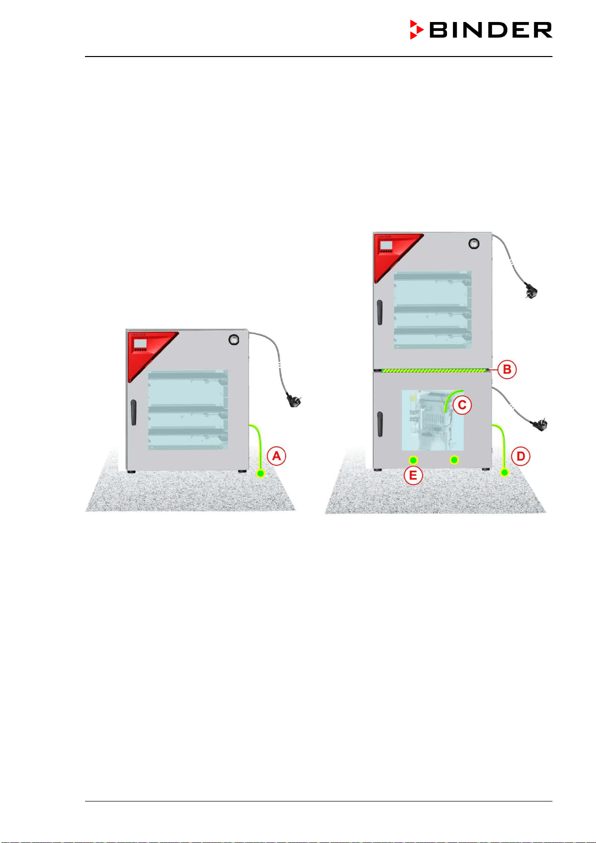
VDL (E3.1) 10/2020 Page 66/196
6.8 Achieving equipotential bonding / Grounding concept
For systems in potentially explosive areas, equipotential bonding acc. to IEC 60079-14 is required. All elec-
trically conductive parts must be connected to the equipotential bonding system. Connections to the equi-
potential bonding system must be secured against automatic loosening.
Grounding, i.e. achieving equipotential bonding is required as solvent vapors may be present during loading
and / or unloading. Also when removing the filled condensate catchpot from the pump solvents may acci-
dentally be spilled. Therefore, the accessible surface of the installation and loading area must be conduc-
tive, there must be technical ventilation, and all equipment (VDL / pump module / vacuum pumpmust be
connected to the conductive surface or to each other according to the grounding concept. The personal
protective equipment (PPE) of the operating personnel must be implemented ESD protected.
Installation without pump module Installation with pump module
Figure 18: Possibilities of grounding (schematic representation)
VDL Vacuum drying oven
M Pump module
S Walkable installation and operating surface with conductive surface
P Vacuum pump
A Equipotential bonding between the VDL and the conductive surface of the installation and loading
area via grounding cable
B Equipotential bonding between the VDL and the pump module via connecting plate
C Equipotential bonding between the vacuum pump and the pump module via grounding cable
D Equipotential bonding between the pump module and the conductive surface of the installation and
loading area via grounding cable
E Equipotential bonding between the condensate collecting tray and the pump module via screws
VDL
M
P
S
VDL
S
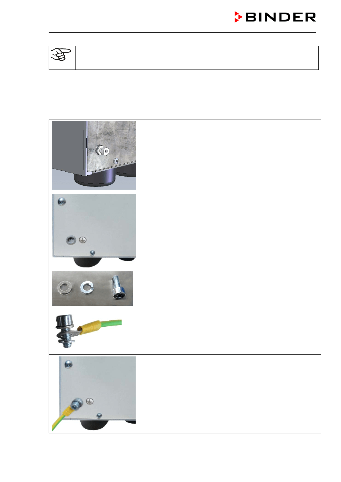
VDL (E3.1) 10/2020 Page 67/196
How to achieve equipotential bonding when installing the VDL with a pump module is de-
scribed in detail in the mounting instructions for the pump module (Art. No. 7001-0137) sup-
plied with the pump module.
Achieving equipotential bonding on the VDL
Equipotential bonding must always be made via external grounding connections, so that no potential can
be introduced in the event of a short circuit. Following the installation of the VDL and having imple-
mented all the measures described to achieve equipotential bonding, we recommend performing a
protective conductor measurement before commissioning.
The VDL provides a threaded bushing for grounding on the bottom
left of the rear panel. In state of delivery the screw together with the
washer and spring washer is screwed on the threaded bushing.
Unscrew the screw.
Threaded bushing after unscrewing
Washer, spring washer, screw
Put the washer, the ring cable lug of the grounding cable and the
spring washer in this order onto the screw.
OR
Put the spring washer, the ring cable lug of the grounding cable, and
the washer directly onto the housing (recommended because this
creates minimum resistance)
Screw on the screw into threaded bushing.
Connected grounding cable
Figure 19: Mounting the grounding cable on the VDL
VDL (E3.1) 10/2020 Page 68/196
DANGER
Explosion hazard by electric sparking due to missing or improperly implemented
equipotential bonding.
Serious injury or death from burns and / or explosion pressure.
Connect all elements in the installation and loading area (VDL / pump module / pump)
with the conductive surface and/or with each other. Proceed according to the grounding
plan in chap. 6.8.
For installation of the pump module proceed acc. to the mounting instructions of the
pump module (Art. no. 7001-0137).
Make sure that the personal protective equipment (PPE) of the operating personnel is
implemented ESD protected. This applies also to gloves.
Before commissioning, measure the equipotential bonding after first setting up the VDL
and implementing all described measures for establishing the equipotential bonding.
Provide cyclic measurements of the equipotential bonding.
Always wear ESD-protected safety clothing when operating the chamber.
6.9 Electrical connection
The chambers are supplied ready for connection. They come with a fixed power connection cable of at
least 2000 mm / 78.74 in in length and a shockproof plug.
Model
Power plug of the
power cable
Nominal voltage
±
10% at the
indicated power frequency
Current
type
Chamber
fuse
VDL 23
Grounded plug
230 V at 50 Hz
230 V at 60 Hz
1N~ 2 x 6,3 A
VDL 56 Grounded plug
230 V at 50 Hz
230 V at 60 Hz
1N~ 2 x 8 A
VDL 115 Grounded plug
230 V at 50 Hz
230 V at 60 Hz
1N~ 2 x 10 A
VDL 23-UL
NEMA 5-15P 100-120 V at 60 Hz 1N~ 10 A
VDL 56-UL
NEMA 5-20P 100-120 V at 60 Hz 1N~ 2 x 16 A
VDL 115-UL
NEMA 5-20P 100-120 V at 60 Hz 1N~ 2 x 20 A
• The domestic socket must also provide a protective conductor. Make sure that the connection of the
protective conductor of the domestic installations to the chamber’s protective conductor meets the latest
technology. The protective conductors of the socket and plug must be compatible!
DANGER
Electrical hazard due to lack of a protective conductor.
Deadly electric shock.
Make sure that the power plug and power socket match and that the protective
electrical conductors of the chamber and domestic installation are securely con-
nected.
• Prior to connection and start-up, check the power supply voltage. Compare the values to the specified
data located on the chamber’s type plate (left chamber side, bottom right-hand, see chap. 1.6).
VDL (E3.1) 10/2020 Page 69/196
NOTICE
Danger of incorrect power supply voltage due to improper connection.
Damage to the equipment.
Check the power supply voltage before connection and start-up.
Compare the power supply voltage with the data indicated on the type plate.
• When connecting, please observe the regulations specified by the local electricity supply company as
well as the VDE directives (for Germany). We recommend the use of a residual current circuit breaker.
DANGER
Electrical hazard due to shock after damage to the device due to pulling on the
electrical connection cable during transport.
Damage to the equipment. Deadly electric shock.
After transport, check the electrical power cable at the installation site to make
sure that it is connected correctly and securely.
∅ Do NOT operate the chamber if the power cable is damaged.
• Pollution degree (acc. to IEC 61010-1): 2
• Over-voltage category (acc. to IEC 61010-1): II
See also electrical data (chap. 28.3).
To completely separate the chamber from the power supply, you must disconnect the power plug. Install
the chamber in a way that the power plug is easily accessible and can be easily pulled in case of danger.
A customer's emergency stop switch or a comparable power disconnector can also be used.
The chamber plug (power plug) is unprotected because it must be disconnected in case of an emergency
to completely separate the chamber from the power supply. Therefore, the electrical connection must be
established outside a zone.
DANGER
Explosion hazard due to sparking when disconnecting an electrical connection.
Serious injury or death from burns and / or explosion pressure.
Make sure that the electrical connection is located outside a zone.
Connect the plug outside the installation area of the VDL and the pump. Take into ac-
count the information on zone classification (chap. 3.5.2)

VDL (E3.1) 10/2020 Page 70/196
7. Explosion safety tests before commissioning
This chapter provides instructions for the user to ensure the safety of the system and to meet applicable
regulations. Proper operation is only ensured after the test has been carried out and any necessary
measures implemented.
Follow the provisions on testing explosion protection according to country-specific regulations (for Germany
in particular TRBS 1201 Part 1; this substantiates the requirements of the Industrial Safety Regulation
(BetrSichV) 2015) within the scope of its application.
7.1 Scope of the functional test
The test represents the entirety of all work equipment relevant to explosion protection. This includes the
vacuum drying oven with all safety, control, and regulation devices, related work equipment such as pumps
or other vacuum systems, pump module, extraction devices, and ventilation systems, gas warning devices,
inerting devices including connection elements as well as the installation area with effective devices for
equipotential bonding and any other building components that may be relevant to explosion protection (non-
exhaustive list).
• Before commissioning and after changes requiring review, perform a comprehensive inspection of the
system in its entirety.
• Systems must be checked in their entirety at least every 6 years.
• Tests can also be carried out by an approved monitoring body or by personnel qualified for testing.
Observe relevant regulations for the qualification requirement.
• Devices, protective systems, safety, control and regulating devices according to Directive 2014/34/EU,
connection devices, and interactions with other parts of the system must continue to be checked at least
every three years. Tests of ventilation systems, gas warning and inerting devices must be performed at
least once per year in the future.
• It may be possible to skip recurring tests, e.g. of devices, protective systems, etc., as well as ventilation
systems, gas warning and inerting devices, if a maintenance plan is provided. The full inspection of the
entire system remains unaffected.
7.2 Explosion protection plan
The explosion protection plan to be created by the operator represents the entirety of the technical and
organizational measures for explosion protection determined and specified on the basis of the risk assess-
ment. In accordance with ATEX Operational Directive 1999/92/EC, these measures serve
• to prevent the formation of or to limit explosive atmospheres or to limit hazardous explosive mixtures
• to avoid the combustion of explosive atmospheres
• to limit the spread of an explosion and to minimize its effects on personnel in order to ensure the health
and safety of employees
The explosion protection document serves to document the results of the risk assessment in accordance
with § 6 Para. 9 GefStoffV (for Germany).
The explosion protection document serves to document the results of the risk assessment in accordance
with § 6 Para. 9 GefStoffV (for Germany).
VDL (E3.1) 10/2020 Page 71/196
7.3 Objective of testing
Determine the suitability and functionality of safety-related measures. When testing the explosion safety of
the system, evaluate the explosion protection plan and compare the target state derived from it with the
actual state of the system (according to available test records):
• Assess the completeness and plausibility of safety-related documents (such as the explosion protection
document, installation plans, zone plans, safety-related figures)
• Determine whether the system has been set up in accordance with national regulation (GefStoffV for
Germany) and is safe for use with regard to explosion protection
• Technical measures are suitable and functional for explosion protection,
• Technical organizational measures necessary for explosion protection are suitable
• The deadline for the next recurring test was correctly set in accordance with national regulations (in
accordance with § 3 Para. 6 BetrSichV for Germany).
Performing tests
The tests can be divided into the verification of the documentation and a technical examination.
7.4 Testing before initial commissioning
Proceed according to country-specific regulations (for Germany in particular: TRBS 1201 Part
1; BetrSichV).
Before the initial commissioning of the Ex system, perform the explosion safety test. It serves to determine
the explosion safety of the system, including the work equipment and the working environment.
The test represents a comprehensive consideration of the explosion safety of the Ex system with regard to
the protection of employees and other persons in the hazard area, including all functional units relevant to
explosion protection and their interactions. The test of explosion safety is based on the explosion protection
plan from the employer in accordance with the specifications in the explosion protection document and its
implementation in the Ex system. Equivalent test results according to other legal regulations can be con-
sidered. It is also permissible to refer to tests that have already been carried out.
7.4.1 Scope of the test
7.4.1.1 Testing the plausibility of the explosion protection plan and measures
Verification of the traceability and plausibility of the explosion protection plan given in the explosion protec-
tion document and the measures derived from this in consideration of underlying constraints.
The test does not apply to systems for which this test has already been carried out in the course of a permit
or approval process.
7.4.1.2 Verifying the implementation of measures
Verification of the measures described in the explosion protection document with regard to their implemen-
tation includes a holistic examination of the technical and organizational measures in accordance with the
specifications of the explosion protection document. Typical test aspects (examples):

VDL (E3.1) 10/2020 Page 72/196
• Suitability and functionality of technical ventilation systems, gas warning systems, inerting devices, de-
vices, protective systems, or control or regulating devices in the sense of Directive 2014/34/EU as well
as explosive devices in the sense of TRGS 725
• Suitability and implementation of the measures determined on the basis of the risk assessment
• Suitability, functionality, and installation of work equipment and related connection devices that are not
devices, protective systems, or safety, control, or regulating devices in the sense of Directive
2014/34/EU, but are relevant for explosion protection
• Suitability of other work equipment, such as ladders, containers, tools, for use in hazardous areas
• Suitability and functionality of other equipment and building components related to explosion protection
(e.g. lightning protection systems, conductivity of floors and linings)
• Suitability of the personal protective equipment (PPE (e.g., the electrostatic discharge capacity of work
shoes or gloves )
• The existence and legibility of the labels for potentially explosive areas in which measures to avoid
ignition sources are required
• The existence and suitability of the organizational measures required for explosion protection
• The implementation of measures relevant to explosion protection from official requirements
• Certificates proving the correct installation of system parts, provided that their correct installation cannot
or only partially be ascertained during the technical inspection, e.g. flame-arresting fittings or limit
switches
7.4.1.3 Checking the deadlines for the recurring tests
When doing so, assess whether the system can be operated safely until the next specified recurring test.
7.4.1.4 Verifying the maintenance plan
When doing so, assess whether the maintenance plan is suitable for maintaining the safety of the Ex system
until the next recurring test. The maintenance plan can also be used to test the technical protective
measures for explosion protection of the explosive system. It can also be part of an integrated management
system.
• Definition of responsibilities for the maintenance plan, definition of maintenance and inspection con-
tent, e.g. when creating work plans, processing the maintenance and inspection content, e.g. in the form
of work plans, the assessment of deviations from the target state, and any necessary repairs.
• Determination of maintenance and inspection measures and deadlines for devices, protective systems,
safety, control and regulating devices as well as their connections and interactions, technical ventilation
systems, gas warning devices and inerting devices and MSR devices for explosion protection
• Comprehensible description of the required maintenance measures and deadlines e.g. in the form of
work plans, work equipment of comparable design can be summarized.
• Implementation of the maintenance plan: Implementation of maintenance and inspection in accordance
with the defined maintenance plan, notification of completion of the implementation of maintenance and
inspection, documentation of identified repair needs and implementation of the repairs. Necessary
maintenance measures must be carried out immediately. Maintenance work must be carried out by
qualified specialist personnel who have sufficient experience in the maintenance of Ex systems based
on the maintenance plan. The maintenance plan and the implementation of maintenance measures
must be clearly documented.

VDL (E3.1) 10/2020 Page 73/196
7.4.2 Tests of technical ventilation systems, gas warning devices, inerting devices, de-
vices, protective systems or safety, control or regulating devices, and other tech-
nical devices for explosion protection
Test content that has been checked and documented as part of conformity assessment procedures do not
need to be checked again. Verify the plausibility and completeness of documents.
The following points must generally be verified:
• Technical ventilation systems, gas warning devices, inerting devices with regard to their suitability, their
functionality, their interconnections, their installation conditions, their proper condition, and their instal-
lation / assembly
• Devices, protective systems, or safety, control, or regulating devices within the meaning of Directive
2014/34/EU on explosion protection with regard to their proper condition, their suitability, their intercon-
nections, their installation conditions, and their installation / assembly
• Safety, control, or regulating devices with relevance for explosion protection, which can also be located
outside the potentially explosive atmospheres, to determine whether ventilation systems, gas warning
devices, inerting devices ensure the proper exclusion of ignition sources and functionality.
• Calibration of the Pt 100 controller sensor and, if required, subsequent adjustment is to be made before
commissioning the chamber as well as part of the annual maintenance. The procedure is described in
the Service manual (customer version).
• Ex devices in the sense of TRGS 725, whether they ensure the necessary functional reliability of the
measures.
• Connection elements and other technical devices (such as lightning protection, requirements for floors)
with regard to their condition, their interconnections, and their installation / assembly for explosion safety
(e.g. type of installation, insulation resistance of electrical cables and lines)
• Take into account the significant interactions of devices, protective systems, safety, control, or regulating
devices and their connecting elements – with each other and with other system parts. This includes, for
example, testing the equipotential bonding, the involvement of pipes in equipotential bonding, overvolt-
age protection, and lightning protection, alignment of units (e.g. pump-coupling-motor).
7.5 Inspection after changes requiring review
There is a need for a change requiring review if the explosive safety of the explosive system is affected by
the change. Changes requiring review are evaluated in accordance with applicable national regulations (for
Germany in particular: TRBS 1123). Checks after a change requiring review may be limited to the changes
made. Verify whether the system in the potentially explosive area has been changed in accordance with
this regulation and is working properly. See the requirements in Chap. 7.4.
7.6 Recurring tests for the explosive safety of the system
Objective of testing: The recurring tests serve to maintain the explosive safety of the Ex system. Among
other things, the actual state of the system is compared with the target state (according to the explosion
protection document and available test records).
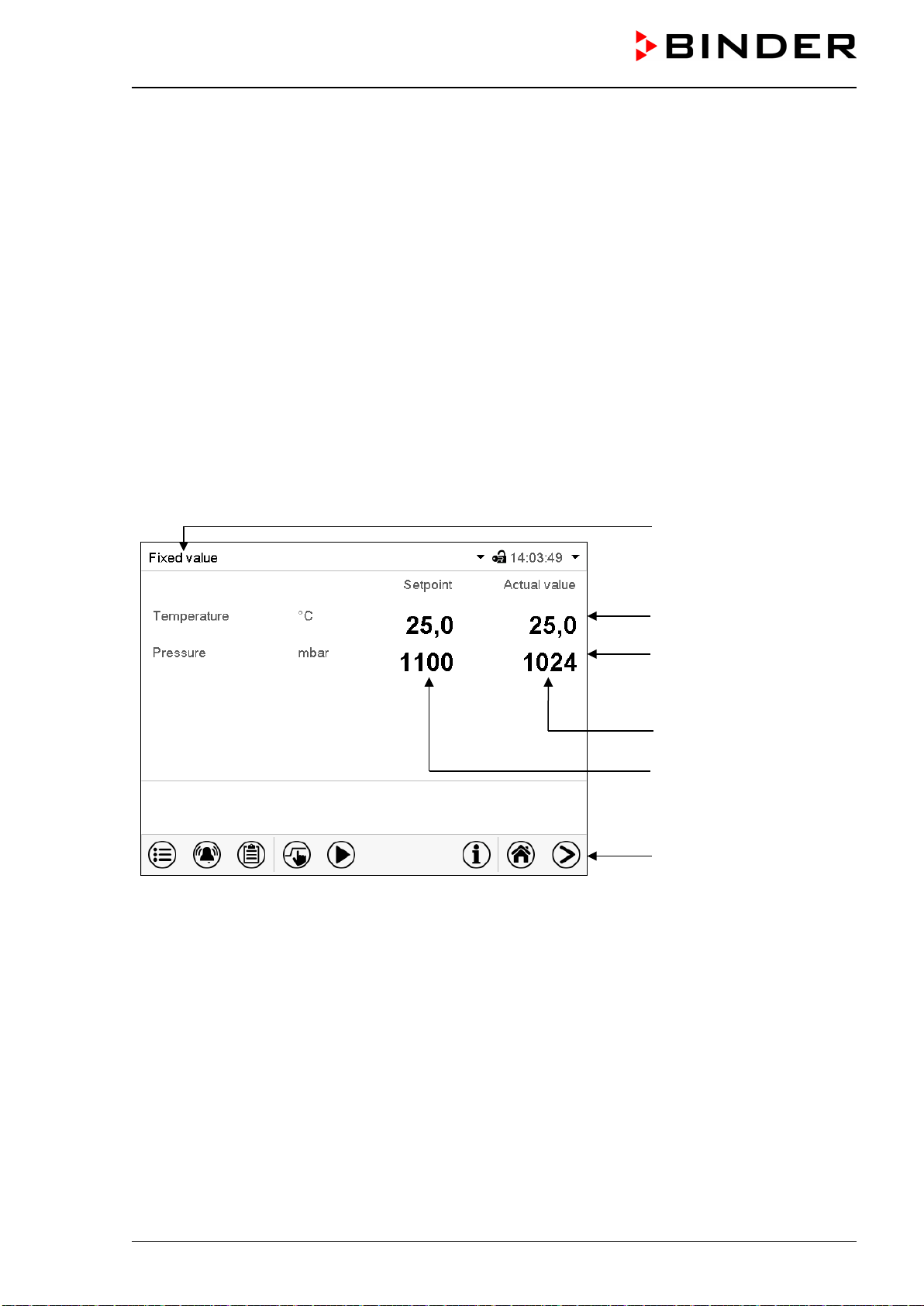
VDL (E3.1) 10/2020 Page 74/196
8. Functional overview and menu structure of the controller
The available controller functions depend on the current authorization (chap.12). Unless noted otherwise,
the figure in this manual show the functional range, which is available for the user with “Admin” authorization
level
The MB2 chamber controller controls following parameters inside the chamber:
• Temperature in °C or °F
• Pressure in mbar
You can enter the desired set point values in fixed value operation mode directly on the display surface or
via the setpoint menu. For program operation the controller offers programming week and time programs.
In addition, there is a timer program available (stopwatch function).
The controller offers various notifications and alarm messages with visual and audible indication and remote
alarms via e-mail, an event list (trace file) and the graphical display of the measuring values in the chart
recorder view. The MB2 program controller permits programming temperature and pressure cycles, and
specifying special controller functions for each program section. You can enter values or programs directly
at the controller or use the APT-COM™ 4 Multi Management Software (option) specially developed by
BINDER.
Operating mode
Temperature values
Pressure values
Actual values
Set-point values
Functional icons
Figure 20: Normal display of the MB2 program controller (sample values)
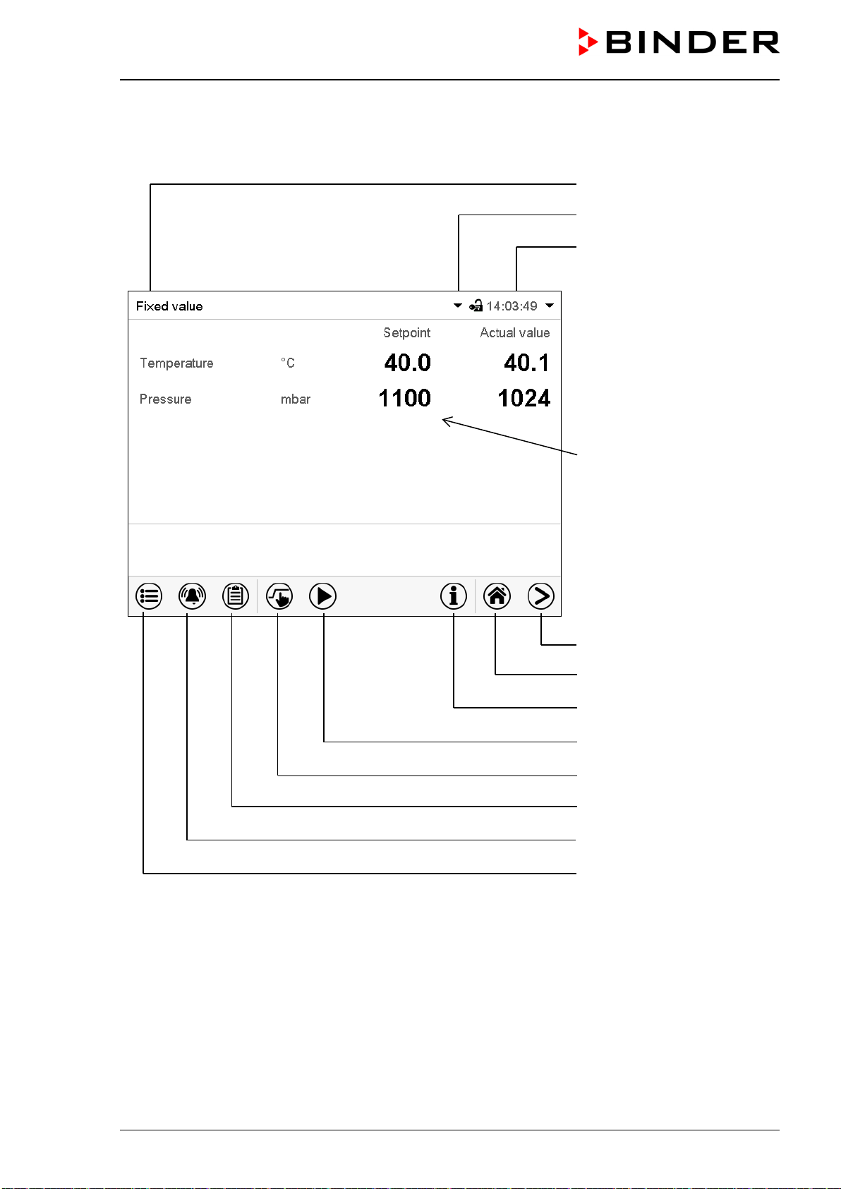
VDL (E3.1) 10/2020 Page 75/196
8.1 Operating functions in normal display
Current operating mode
Text list for information icons
Date, time, authorization level of
the logged-in user, memory
Quick setpoint entry
Continue to next screen
Back to Normal display
Information
Program start
Setpoint entry
Event list
Display of active alarms
Access to main menu
Figure 21: Operating functions of the MB2 controller in normal display (example values)
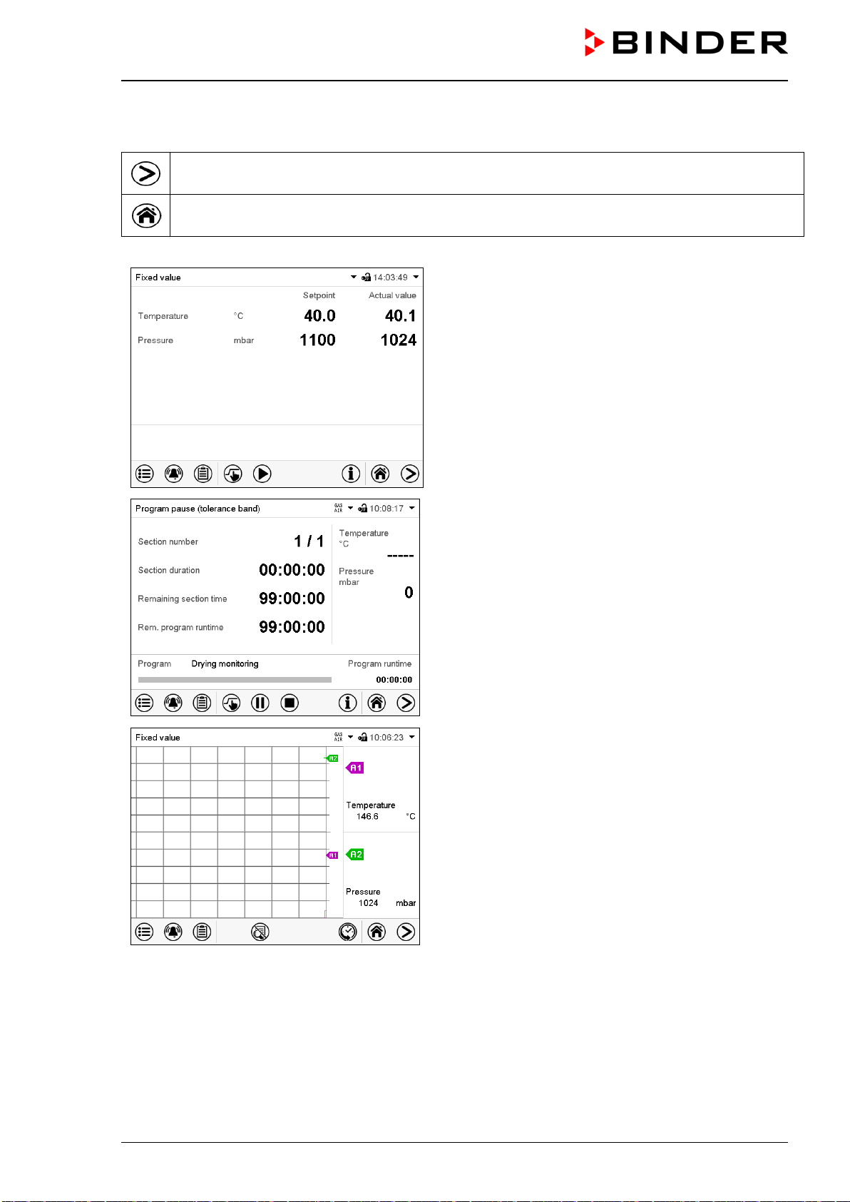
VDL (E3.1) 10/2020 Page 76/196
8.2 Display views: Normal display, program display, chart-recorder display
Press the Change view icon to toggle between normal display, program display and chart-re-
corder display.
Press the Normal display icon to return from program display and chart recorder display back to
Normal display.
Normal display (actual values / setpoint values)
Program display (example: time program)
Chart recorder display
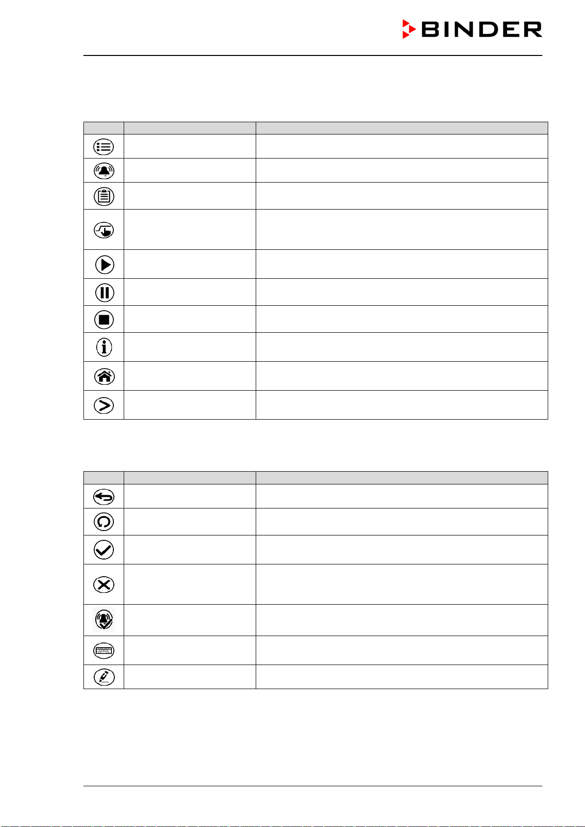
VDL (E3.1) 10/2020 Page 77/196
8.3 MB2 controller icons overview
Navigation icons in Normal display
Icon
Signification
Function
Main menu Access from Normal display to the main menu
Alarm Access from Normal display to the list of active alarms
Event list Access from Normal display to the event list
Setpoint setting
Access from Normal display to the setpoint entry menu: setpoint
entry for Fixed value operation, turning on/off temperature and/or
pressure control, safety controller settings
Program start
Start a previously entered time or week program,
continue a paused time program
Program pause Pause a running time program
Program cancelling Cancel a running time or week program
Information
Information on program operation, setpoints, actual values, and
the safety controller
Normal display
Return from program display or chart recorder display to Normal
display
Change view
Toggle between Normal display, program display, and chart re-
corder display
Functional icons in individual menus
Icon
Signification
Function
Back Return from each menu to Normal display
Update Update the event list and alarm messages
Confirm
Take over the entries and exit the menu / continue menu se-
quence.
Close
Exit the menu / cancel menu sequence. Entries are not taken
over. When terminating a menu sequence, an information win-
dow appears, which must be confirmed.
Reset alarm Acknowledge the alarm and mute the buzzer.
Change keyboard
Change between uppercase and lowercase characters, digits
and special characters
Edit Edit settings of time and week programs
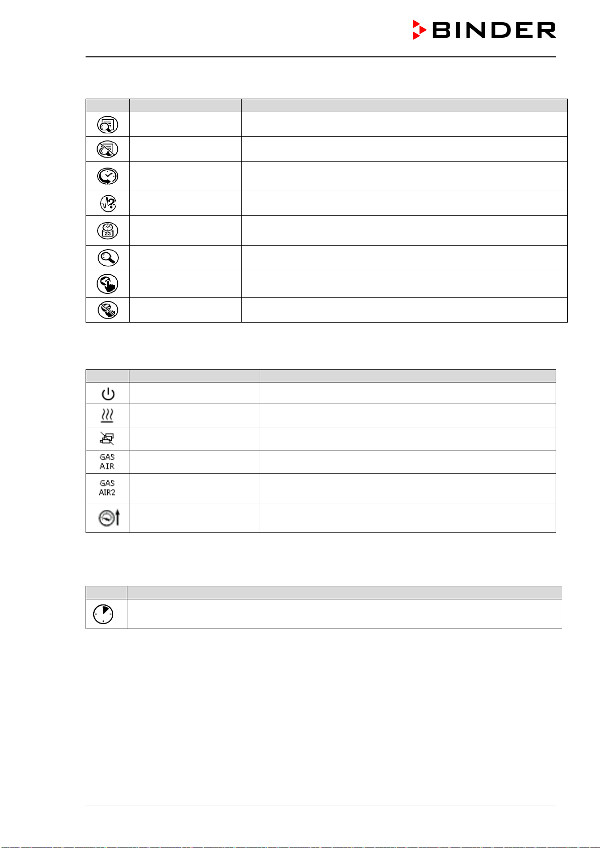
VDL (E3.1) 10/2020 Page 78/196
Functional icons in the chart recorder display
Icon
Signification
Function
Show legend Show legend
Hide legend Hide legend
History display
Pause chart recorder and change to history display. Data recording
continues.
Curve selection Go to “Curve selection” submenu in the history display
Search
Go to “Search” submenu in the history display to select the required
instant
Zoom Go to “Zoom” submenu in the history display to select the zoom factor
Show scroll buttons Show scroll buttons in the history display to scroll to an instant
Hide scroll buttons Hide scroll buttons in the history display to scroll to an instant
Information icons referring to chamber conditions
Icon
Text information
Condition
“Standby” Chamber is in Standby mode
“Heating active” Chamber is heating up
“All valves are closed” All valves are closed
“GAS/AIR” Ventilation via regular connection “GAS/AIR” (4)
“GAS/AIR 2”
Ventilation via optional connection “GAS/AIR2” (5)
Regular connection “GAS/AIR” (4) deactivated.
“Press.thresh. not
reached”
Pressure threshold of 100 mbar not reached
Information icon for data processing
Icon
Information
Waiting icon: Data processing is running.
Remaining time to touch the display when calibrating the touchscreen.
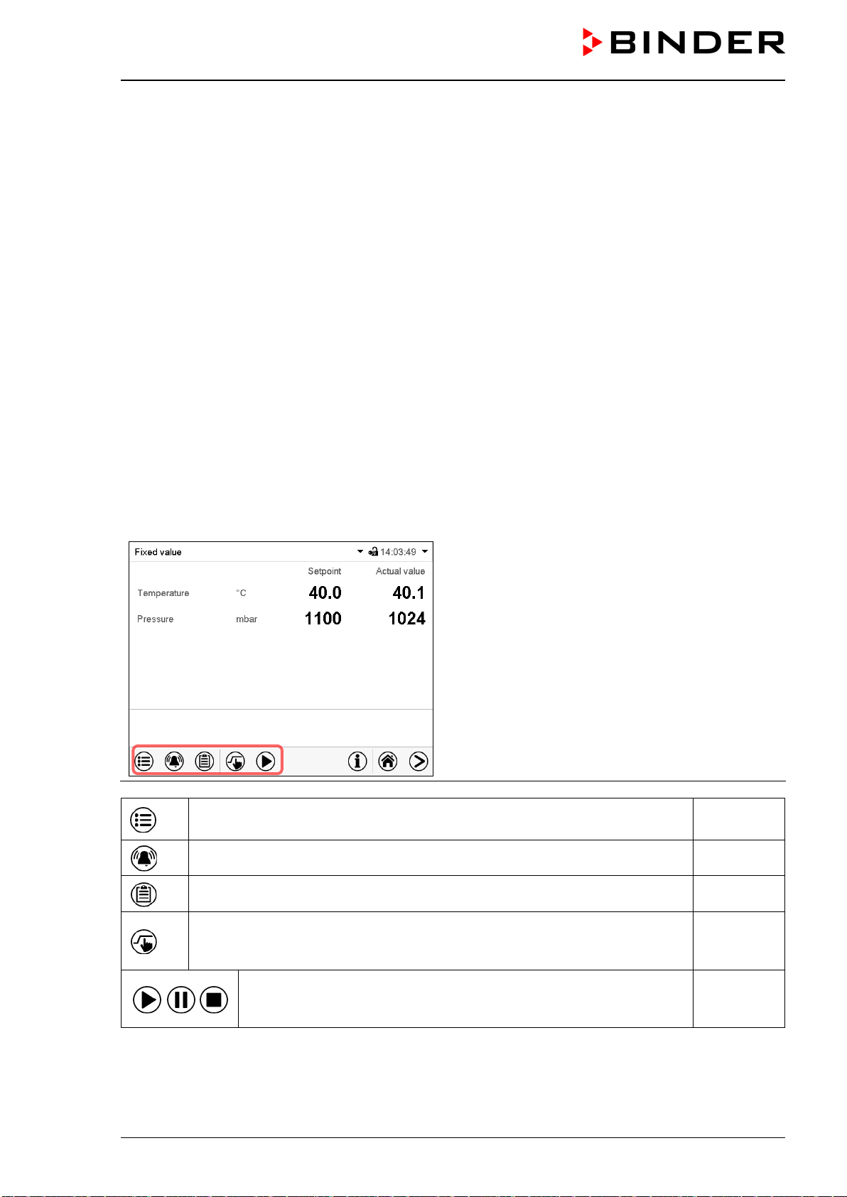
VDL (E3.1) 10/2020 Page 79/196
8.4 MB2 controller operating modes
The MB2 program controller operates in the following operating modes:
• Fixed value operating mode
The controller operates as a fixed-point controller, i.e., set-points for temperature and pressure can be
defined, which are then maintained until the next manual change (chap. 10.1.1).
• Timer program operation
Stopwatch function: during an entered duration the controller constantly equilibrates to the setpoints
entered in Fixed value operation mode.
• Time program operation
An entered time program for temperature and pressure is running. The controller offers 25 program
memory places with 100 program sections each. The total number of program sections of all programs
is unlimited
• Week program operation
An entered week program for temperature and pressure is running. The controller offers 5 program
memory places with 100 switching points each. The switching points can be distributed over all days of
the week.
8.4.1 MB2 controller menu structure
Use the navigation icons in the screen footer in
Normal display to access the desired controller
functions.
The available functions depend on the current au-
thorization level “Service”, “Admin” or “User”
(chap. 12.1. This is selected either during login or
can be available without password protection.
Main menu: program settings, further information, “Service” submenu.
The “Settings” submenu allows general configuration of the controller.
chap. 8.4.2
List of active alarms chap. 16.2
Access to the event list chap. 13.5
Setpoint entry for Fixed value operation, Standby mode, turning on/off
temperature and/or pressure control, safety controller settings
chap.
10.1.1,
11.5, 14.2.2
Start/ pause/ cancel an already entered, respectively a running time
program or start / cancel an already entered, respectively a running
week program
chap. 18.1,
18.2, 19.1
Unless noted otherwise, the figures show the functional range, which is available for the user with “Admin”
authorization level.
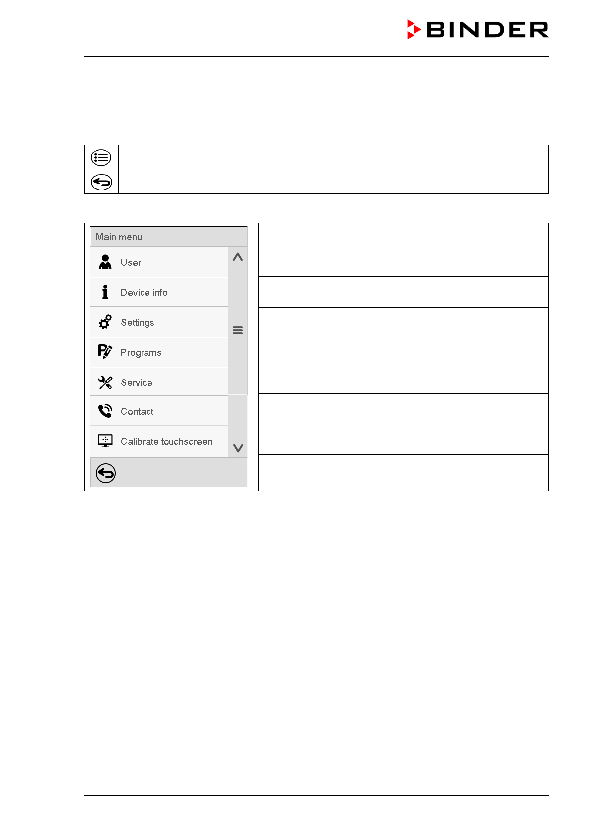
VDL (E3.1) 10/2020 Page 80/196
8.4.2 Main menu
The main menu provides access to the general configuration of the controller as well as to program entry
and the user administration. Additionally, there are support functions like a contact page or the display
calibration depending on the available angle.
Press the Main menu icon to access the main menu from Normal Display.
Press the Back icon to return from each setting menu to Normal Display.
The main menu provides the following functions and submenus.
User management: login and logout, pass-
word management
chap. 12.1
Chamber information chap. 13.8
“Settings” submenu (not visible for user with
“User” authorization level)
chap. 13
“Programs” submenu (not visible for user
with “User” authorization level)
chap. 18 und 19
“Service” submenu chap. 8.4.4
BINDER Service contact page chap. 13.6
Calibrating the touch screen chap. 13.4.2
Back to Normal Display
“Settings” submenu
• Settings of many general controller functions and network settings (chap. 13).
• Available only for users with “Service” and “Admin” authorization level
“Service” submenu
• Access to service data, controller reset to factory settings (chap. 8.4.4)
• Available only for users with “Service” and “Admin” authorization level. Full functional range only for
BINDER Service (users with “Service” authorization level).
“Programs” submenu
• Access to the controller’s program functions (chap. 17, 18, 19)
• Available only for users with “Service” and “Admin” authorization level.
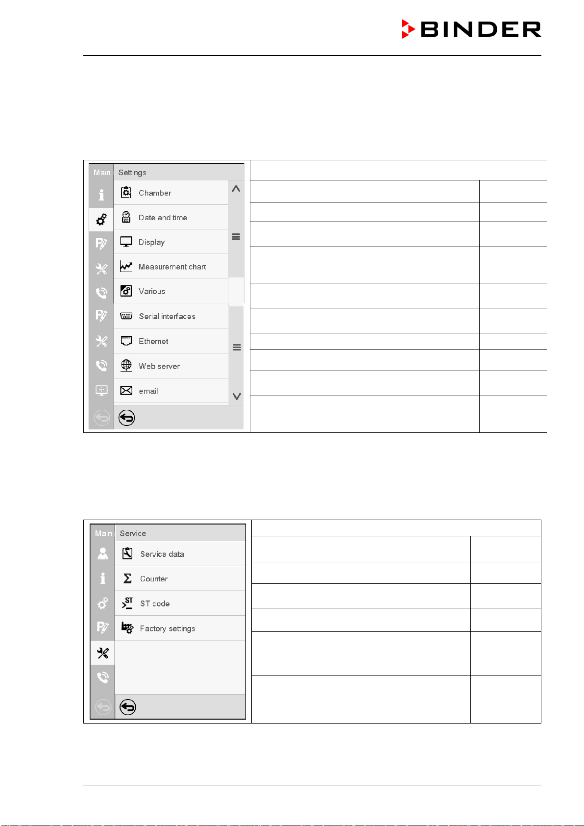
VDL (E3.1) 10/2020 Page 81/196
8.4.3 “Settings” submenu
The “Settings” submenu is available for users with “Service” or “Admin” authorization level. It serves to
enter date and time, select the language for the controller menus and the desired temperature unit and to
configure the controller’s communication functions.
Path: Main menu > Settings
Setting the temperature unit, menu language… chap. 13.1,
Setting date and time chap. 13.2
Setting the display brightness, continuous opera-
tion and screen saver
chap. 13.4
Settings for the measurement chart: storage inter-
val, storage values, minimum and maximum val-
ues
chap. 22.2
Setting the tolerance range and delay time for tol-
erance range alarm
chap. 15
(not used)
Entry of the MAC address and IP address chap. 20.1
Password protection for web server access chap. 20.2
Configuration of the e-mail server, assignment of
e-mail addresses
chap. 20.3
Back to main menu
8.4.4 “Service” submenu
The “Service” submenu is available for users with “Service” or “Admin” authorization level. When logged-in
with “Admin” authorization level the user will find information to tell the BINDER Service in service case.
Path: Main menu > Service
Serial number of the chamber, setup version of
the controller software
chap. 13.8
No function
Information for BINDER Service
Reset to factory settings
Back to main menu
(view with “Admin” authorization level)
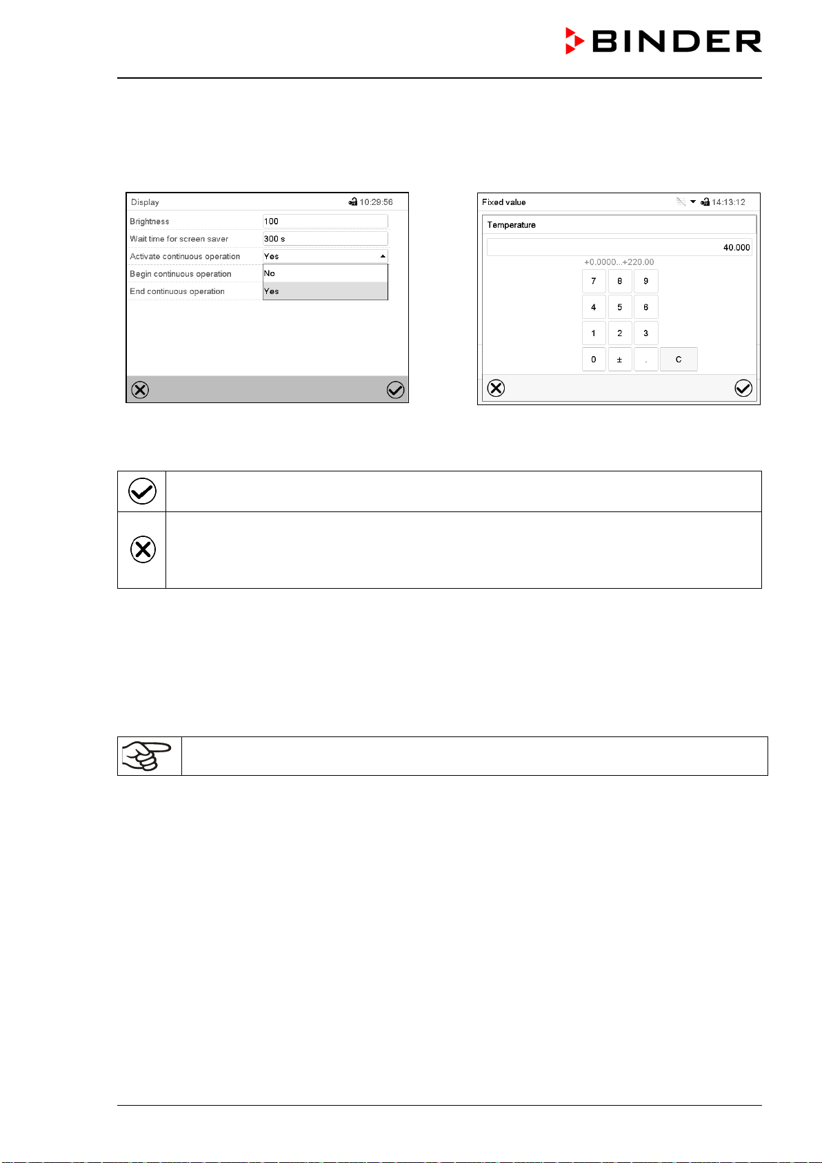
VDL (E3.1) 10/2020 Page 82/196
8.5 Principle of controller entries
In the selection and entry menus there are icons displayed in the footers which you can use to take over
the entry or cancel it.
Selection menu (example)
Entry menu (example)
After completing the settings there are the following possibilities:
Press the Confirm icon to take over the entries and exit the menu or continue the menu se-
quence.
Press the Close icon to exit the menu or cancel the menu sequence without taking over the
entries.
When terminating a menu sequence, an information window appears, which must be con-
firmed.
8.6 Performance during and after power failures
During a power failure, all controller functions are shut down.
If there is a vacuum and ventilation is required during the duration of the power failure, this is possible via
the emergency ventilation (chap. 9.9.3).
After the power returns, all functions return to the same status the chamber had before power failure.
All settings and set point values remain in the memory during power failure.
• If the Standby mode had been activated prior to the power failure, the chamber remains off after the
power returns. To operate it you must sign in with a higher authorization level and deactivate the standby
mode.
• If the Standby mode had been deactivated prior to the power failure, operation continues after the power
returns with previously entered parameters. If the pressure reaches or falls below the required pressure
threshold of 100 mbar, the heater turns on depending on the setpoint.
After the power returns, the controller continues to function in the original operating mode it was in previ-
ously before the power failure occurred:
• Performance after power failure in Fixed value operation mode
All functions return to the same status the chamber had before power failure. The set-points are imme-
diately resumed.
• Performance after power failure during Timer operation
The set-points which had been active at the moment of program start are resumed. Program run con-
tinues.

VDL (E3.1) 10/2020 Page 83/196
• Performance after power failure during Time program operation
The program is resumed at the point where the interruption occurred with the latest set-points reached
during the program run.
• Performance after power failure during Week program operation
The week program continues with the values corresponding to the current time.
Power failure and power return are noted in the Event list (chap. 13.5).
If during power failure an alarm has occurred (e.g., tolerance range, safety controller), confirm the alarm.
See chap. 16.3.
9. Start up and performing the drying process
With regard to operating the vacuum drying oven VDL and to the installation location, please observe the
relevant national regulations (for Germany in particular: DGUV guidelines 213-850 on safe working in la-
boratories, issued by the employers’ liability insurance association; Industrial Safety Regulation (Be-
trSichV); Ordinance on Hazardous Substances (GefStoffV); Technical Regulations on Industrial Safety and
Health (TRBS 1201 Part 1).
Note: Warming chambers may release odors in the first few days after commissioning. This is not a quality
defect. To reduce odors quickly we recommend heating up the chamber to its nominal temperature for one
day and in a well-ventilated location.
Do not start up the chamber without technical ventilation (chap. 5.2.2).
9.1 Requirements for safe commissioning
Prior to turning on the chamber, the following points must certainly be met:
• Installation of the chamber (chap. 6) performed in compliance with the installation guidelines and ambi-
ent conditions (chap. 5)
• Compressed air connection established for sweeping the electrical installation room, the preheating
chamber (heating area between inner and outer chamber) and the controller housing. The compressed
air supply line provided by the operator must be equipped with active monitoring of the defined inlet
pressure (2 bar).
• Vacuum supply connected (chap. 6.5)
• If required: Inert gas connection established (chap. 6.6)
• Equipotential bonding established (chap. 6.8)
• Observing all safety instructions
• Upon initial commissioning: Test before initial commissioning performed and passed (Chap. 7.4)
• Upon recommissioning after maintenance / repairs / changes requiring review: Test performed and
passed (Chap. 7.5)
• Technical ventilation activated
• Power connection established (chap. 6.9).
VDL (E3.1) 10/2020 Page 84/196
9.2 Overview of the drying process
Required measures for operation with solvent-containing substances, which may be able to form an explo-
sive mixture with air:
Starting situation
• The vacuum drying oven and additional equipment have been set up and installed in ac-
cordance with the instructions in this manual, the instructions of the operator and the rele-
vant regulations. Equipotential bonding according to the grounding concept is ensured
□
• The auto-ignition temperature of the solvent has been determined from its safety specifica-
tions
In the case of solvent mixtures, use the lowest auto-ignition temperature.
□
• All users have been trained and are familiar with the safety plan and the required measures.
□
• The vacuum source is connected and ready for operation
□
• The technical ventilation is activated.
□
• The compressed air supply is connected and ready for operation. The monitoring of the
defined inlet pressure (2 bar) is active.
□
Sweeping the area for electrical equipment, the preheating chamber, and controller housing
(triangular instrument box)
• Turn the pressure regulator on the chamber rear until the clamping ring touches the lower
stop (turn clockwise).
□
• Open the sweeping plug on the chamber rear and the USB cover on the controller housing.
□
• Sweep the electrical installation room, the preheating chamber and the controller housing
with compressed air for the specified duration (chap. 9.3.2) at maximum overpressure
□
• Close the sweeping plug on the chamber rear and the USB cover on the controller housing
□
• Now the pressure regulator can be turned back (counter-clockwise rotation) until the clamp-
ing ring touches the upper stop. (only tighten to the stop by hand)
• Check on the manometer that an overpressure of at least 25 Pa (recommendation: >40 Pa)
has been reached
□
Loading and starting the drying process
• Make sure that the technical ventilation is activated
□
• Make sure that equipotential bonding has been established according to the grounding con-
cept
□
• Make sure that the sweeping times of the electrical installation room, preheating chamber,
and controller housing (triangular instrument box) have been observed
□
• Make sure that the compressed air supply for sweeping the electrical installation area, pre-
heating chamber, and controller housing is still open. Check the excess pressure of at least
25 Pa on the manometer (recommendation: >40 Pa).
□
• In case of Standby mode turn on the vacuum drying oven on the controller
□
• Set the desired temperature setpoint on the controller.
□
• Set the safety controller to a suitable value.
Recommended setting: safety controller mode: Limit, safety controller value approx. 5 °C
above the temperature set-point
□
VDL (E3.1) 10/2020 Page 85/196
• Make sure that the user's equipment is ESD protected.
• Place the material to be dried in the chamber.
□
• Set the pressure set-point on the controller.
Heating will start only when a vacuum corresponding to the pressure threshold of 100 mbar)
is reached.
□
The drying process is running.
After completing the drying process or when cancelling the drying process
When the pressure drops to the pressure set-point, the drying process is finished. If the drying monitor-
ing (chap. 11.6) is activated, a corresponding message is displayed.
• Make sure that the technical ventilation is activated
• Make sure that equipotential bonding has been established according to the grounding con-
cept
□
• For ventilation, set the pressure set-point to atmospheric pressure
□
• Switch the vacuum drying oven on the controller to standby mode (not completely de-ener-
gized)
□
• Make sure that the user's equipment is ESD protected.
• Remove the drying material
□
• Continue sweeping the electrical installation area, preheating chamber and controller hous-
ing with an overpressure of at least 25 Pa (recommendation: >40 Pa) for at least 10 minutes
(recommended). Check the excess pressure on the manometer. Only then shut off the com-
pressed air supply.
□
For emptying the pump
• Make sure that the pump is turned off.
□
• Make sure that the technical ventilation is activated
• Make sure that equipotential bonding has been established according to the grounding con-
cept
□
• Make sure that the user's equipment is ESD protected.
• Remove the full condensate catchpot of the pump
□
Before starting a new drying process
In case of a new solvent with a different auto-ignition temperature:
• Determine the auto-ignition temperature of the solvent from its safety specifications. In the
case of solvent mixtures, use the lowest auto-ignition temperature
□
• Make sure that the technical ventilation is activated
• Make sure that equipotential bonding has been established according to the grounding con-
cept
□
• Sweep the area for electrical equipment, preheating chamber and the controller housing
with compressed air at maximum overpressure for a defined time (chap. 9.3.2).
□
• Turn on the chamber and check the settings (drying temperature, pressure set-point and
safety controller setting)
□
• Now you can load the chamber and start the new drying process. Follow all safety measures
□
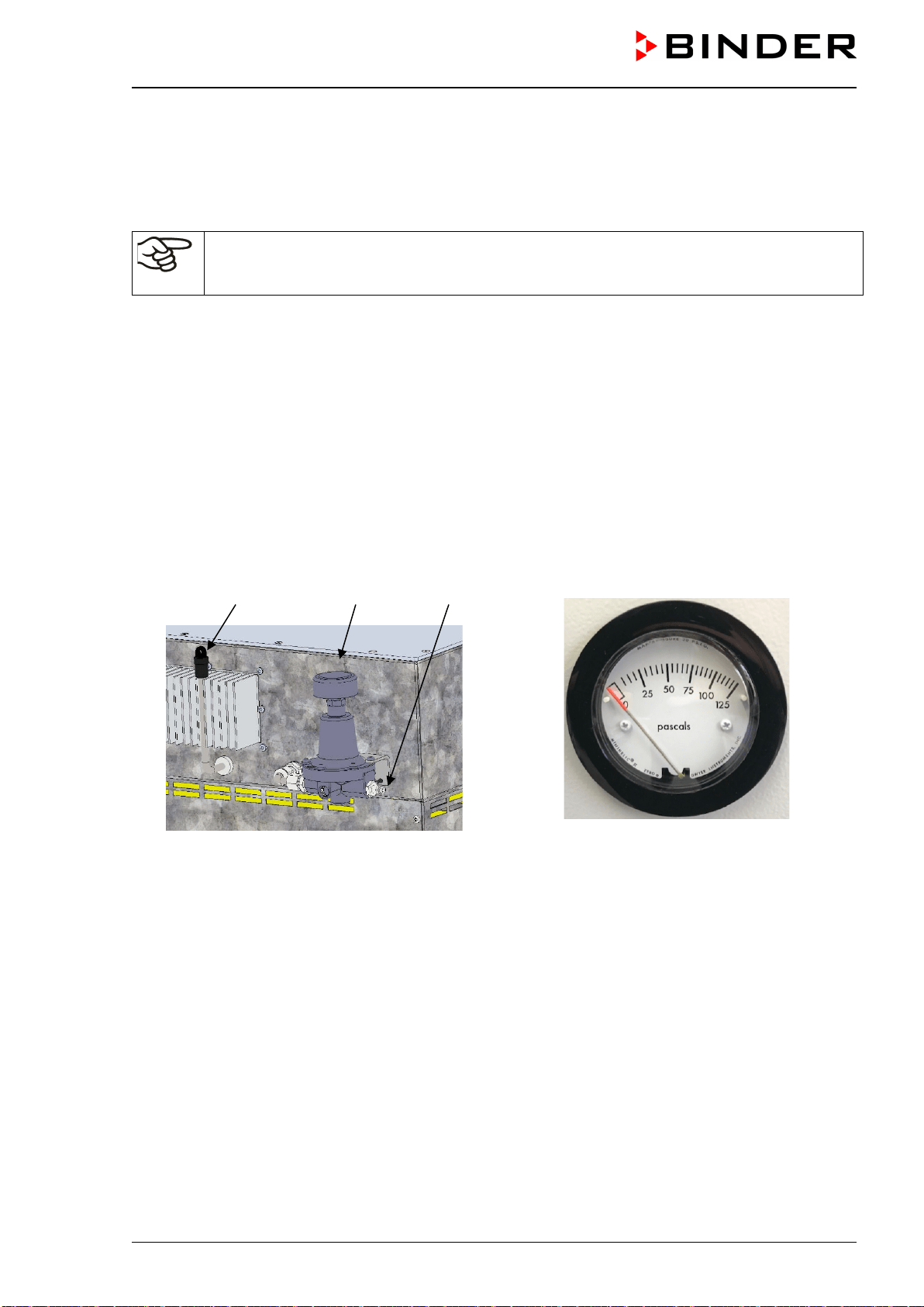
VDL (E3.1) 10/2020 Page 86/196
9.3 Sweeping the area for electrical equipment, the preheating chamber, and
the controller housing (triangular instrument box) with compressed air
To sweep the area for electrical equipment, the preheating chamber, and the controller housing, activate
the customer's compressed air supply.
The compressed air supply line provided by the operator must be equipped with active moni-
toring of the defined inlet pressure (2 bar), which clearly indicates a drop and increase in the
inlet pressure outside the permissible tolerance of ±0.2 bar.
9.3.1 Setting the pressure regulator for sweeping with compressed air
After opening the pressure regulator on the chamber rear (turn clockwise), the area for electrical equipment
of the oven, the preheating chamber (the heater area between the inner and outer chamber) and the con-
troller housing will be swept. Compressed air is used and then released into the surrounding atmosphere
independent of the oven’s operating state.
Compressed air sweeping must be in operation for a defined time (chap. 9.3.2) before turning on the cham-
ber. It remains in operation during the entire use of the chamber (loading, drying, removal of the material
to be dried), with an overpressure of at least 25 Pa (recommendation: >40 Pa). This operating point is
defined on the pressure regulator when the clamping ring touches the upper stop. After terminating the
drying procedure and turning off the chamber it is recommended to continue sweeping for approx. 10
minutes.
On the chamber front there is an analog pressure display (manometer) to show the existing overpressure.
(11) (9) (10)
Figure 22: Pressure regulator and sweeping plug
for compressed air sweeping on the chamber rear
Figure 23: analog pressure display (manometer)
for compressed air sweeping on the chamber
front
(9) Pressure regulator for compressed air sweeping
(10) Connection for compressed air sweeping / overpressure
(11) Outlet with sweeping plug for compressed air sweeping before start-up
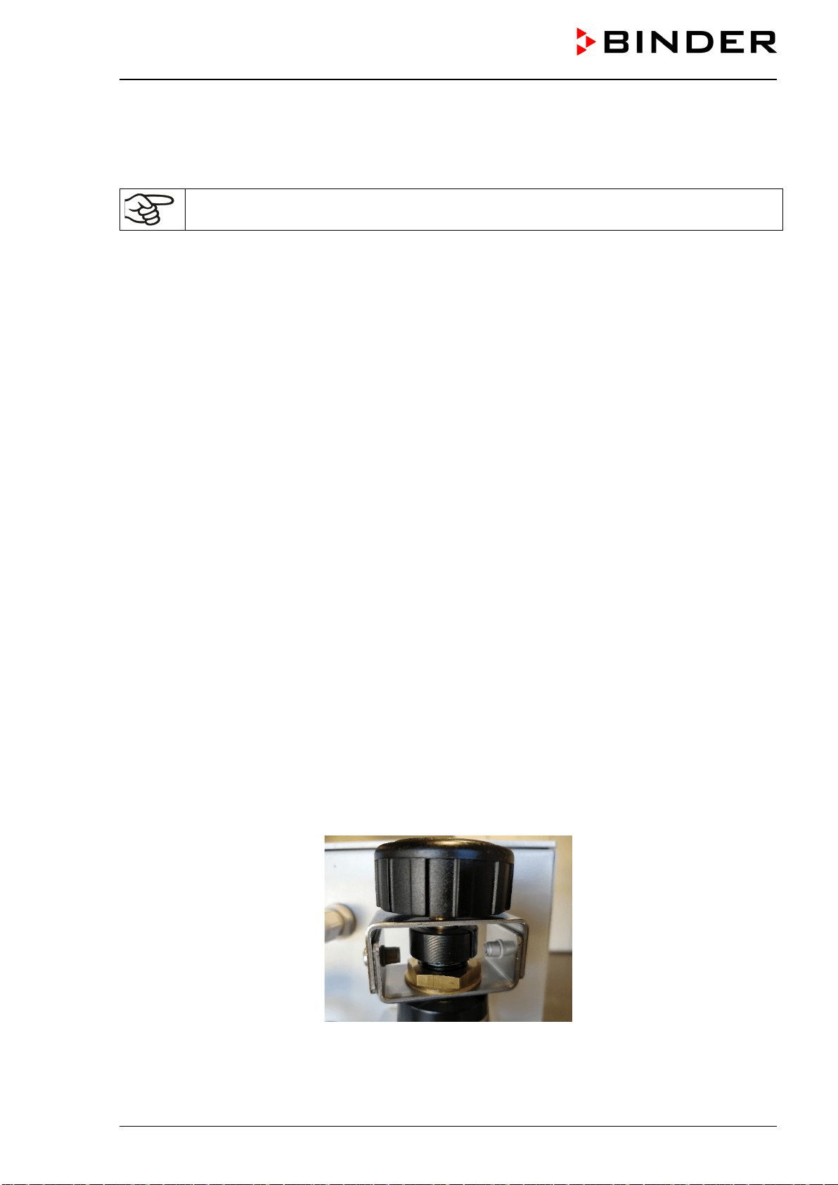
VDL (E3.1) 10/2020 Page 87/196
9.3.2 Sweeping before starting up / restarting the chamber
Before turning on the VDL it is mandatory to sweep the area for electrical equipment, the preheating cham-
ber and controller housing with compressed air at maximum overpressure for a defined time.
Compressed air sweeping before start-up takes place in two steps. Be sure to follow the given
order.
Sweeping the electrical installation room, preheating chamber and controller housing (instrument
triangle)
• Turn the pressure regulator until the clamping ring touches the lower stop (turn clockwise). This gives
the maximum overpressure.
• Open the sweeping plug on the chamber rear next to the pressure regulator
• Check that compressed air flows out of the sweeping plug (caution, the outflowing air may be hot)
• Open the USB cover on the controller housing (instrument triangle)
• Check if compressed air is coming out of the USB cover (caution, the outflowing air may be hot)
• Sweep with maximum overpressure for at least the following duration
VDL 23: 20 minutes
VDL 56: 30 minutes
VDL 115: 40 minutes
• Then close the sweeping plug on the chamber rear.
• Also connect the USB cover on the controller housing (instrument triangle)
• Now the pressure regulator can be turned back (counter-clockwise rotation) until the clamping ring
touches the upper stop. (Only tighten to the stop by hand)
• Check that there is an overpressure of at least 25 Pa (recommendation: >40 Pa).
9.3.3 Sweeping during chamber operation
Sweeping the electrical installation room, the preheating chamber and controller housing must take place
with an overpressure of at least 25 Pa (recommendation: >40 Pa) during the entire operation of the vacuum
drying oven. This operating point is defined on the pressure regulator when the clamping ring touches the
upper stop. Also after termination or cancellation of the drying process continued sweeping for at least 10
minutes is recommended.
Figure 24: Pressure regulator with defined setting at the upper stop
VDL (E3.1) 10/2020 Page 88/196
DANGER
Explosion hazard by solvent-containing air penetrating and concentration in the
electrical area of the chamber and at the heater.
Serious injury or death from burns and / or explosion pressure.
Make sure that sweeping the area for electrical equipment, preheating chamber, and
controller housing with compressed air for the defined time (chap. 9.3.2) at maximum
overpressure has been done before turning on the chamber.
Make sure that sweeping the area for electrical equipment, preheating chamber, and
controller housing with compressed air with an overpressure of at least 25 Pa (recom-
mendation: >40 Pa) takes place during the entire operation.
Ensure that the compressed air supply line provided by the operator is equipped with
active monitoring of the defined inlet pressure which clearly indicates a drop and in-
crease in the inlet pressure outside the permissible tolerance of ± 0.2 bar
Proceeding
• The sweeping plug on the chamber rear and the USB cover on the controller housing must be closed
• Adjust the pressure regulator until the clamping ring touches the upper stop. (Only tighten to the stop by
hand)
• Check this display during operation of the chamber. In all operating states, the value on the manometer
must show an overpressure of at least 25 Pa. Recommended value: >40 Pa.
Regarding use of the USB connection during chamber operation please observe the instruc-
tions given in chap. 21.1.
9.3.4 Sweeping after completion of chamber operation (recommended):
• You can stop sweeping 10 minutes after turning off the chamber: Close the pressure regulator to (turn
counterclockwise).
• Then you can close the compressed air supply.
• Check on the manometer that there is no longer any overpressure.
9.4 Condition after establishing the power connection
Only trained personnel with key-authorization may work on the VDL vacuum drying oven.
Prior to establishing the power connection, the following points must certainly be met:
• Installation of the chamber (chap. 6) performed in compliance with the installation guidelines and ambi-
ent conditions (chap. 5)
• Vacuum supply connected (chap. 6.5)
• If required: Inert gas connection established (chap. 6.6)
• Equipotential bonding established (chap. 6.8)
• Upon initial commissioning: Test before initial commissioning performed and passed (chap. 7)
• Technical ventilation is activated
• Sweeping the area for electrical equipment, preheating chamber, and controller housing with com-
pressed air for the defined time (chap. 9.3.2) at maximum overpressure has been done
Establish the power connection: connect the power plug (chap. 6.9). Connect the power supply only when
needed, and disconnect it when the chamber is not in use for an extended period.
VDL (E3.1) 10/2020 Page 89/196
After establishing power supply the pilot lamp in the controller housing shows readiness for operation.
The authorization level is “User”. To be able to use the entire functionality of the controller, log in with the
desired authorization level.
All parameters, set-points and settings remain the same as before turning off.
• If the Standby mode had been activated prior to the power failure, the chamber remains off after the
power returns. To operate it you must sign in with a higher authorization level and deactivate the standby
mode.
• If the Standby mode had been deactivated prior to the power failure, operation continues after the power
returns with previously entered parameters. If the pressure reaches or falls below the required pressure
threshold of 100 mbar, the heater turns on depending on the setpoint
9.5 Standby mode Turning on and off the vacuum drying oven
Before turning on the chamber, the following points must surely be met:
• Equipotential bonding established (Chap. 6.8)
• Technical ventilation is activated
• Sweeping the area for electrical equipment, preheating chamber, and controller housing with com-
pressed air for the defined time (chap. 9.3.2) at maximum overpressure has been done
Activate the chamber only as required. Switch the chamber to standby mode when it is not in use.
In standby mode no solvents may remain inside the chamber!
Before turning off the chamber (activating standby mode), completely remove all solvents from
the chamber and its surroundings.
All settings and target values remain saved in standby mode.
If a program is running, it will be canceled by activating the standby mode
In Standby mode, the heating is off, and all valves are closed. Heating control and pressure control are off.
To completely separate the chamber from the power supply, you must disconnect the power plug.
For decommissioning observe the guidelines in chap. 27.2.
Required authorization: “Admin”.
Press the Setpoint setting icon to access the “Setpoint” setting menu from Normal display.
Path: Setpoint > Fixed value operation setpoints > Functions on/off
In this menu you can activate and deactivate the Standby mode .
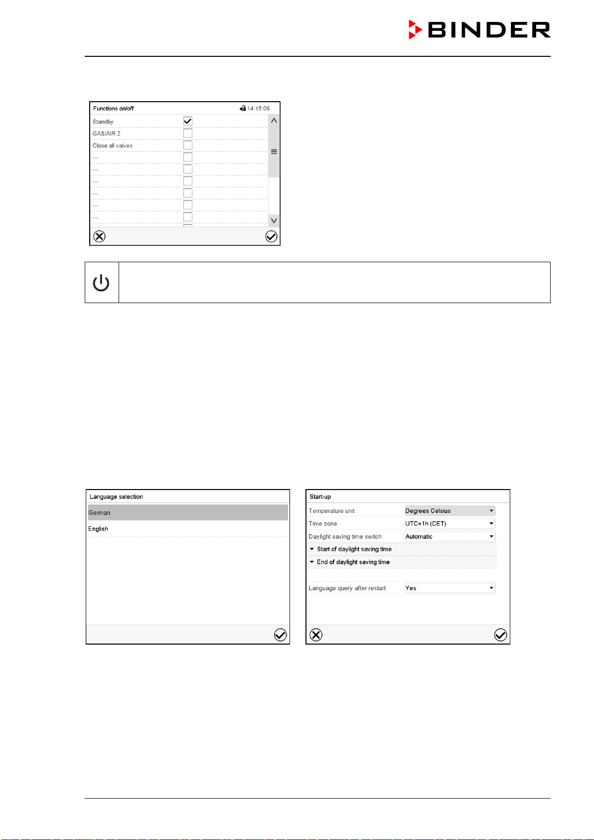
VDL (E3.1) 10/2020 Page 90/196
Activating the Standby mode (turning off the chamber):
“Functions on/off” menu
Mark the checkbox of the function “Standby” to activate
it and press the Confirm icon.
In the “Setpoints” menu press again the Confirm icon.
The controller changes to Normal display.
When the function “Standby” is activated, the “Standby” icon is displayed in the screen header
in Normal display. Press the flash icon next to the information icon to display the corresponding
text information “Standby” (information messages, chap. 16.1).
When the controller display is dark in standby mode, press on the touchscreen to activate it for 10 seconds.
Deactivating the Standby mode (turning on the chamber
To deactivate the “Standby” function, unmark the checkbox.
9.6 Controller settings upon start up
Depending on the functions activated in the controller, various settings can be requested directly after turn-
ing on the chamber.
Then you should assign a password for the operating level (chap. 12).
The window “Language selection” enables the language selection, in case that it’s activated in the “Start-
up” menu. Afterwards occurs a request of the time zone and the temperature unit.
The controller will function in the operating mode, which was active before the last shut-down. It controls
temperature and pressure in fixed value operating mode to the last entered values and in the program
mode to the set points achieved beforehand.
Locked operation
Provided that the user administration has been activated by the assignment of passwords for the different
authorization types, the controller operation is first locked after turning on the unit, recognizable by the
closed lock icon in the header.
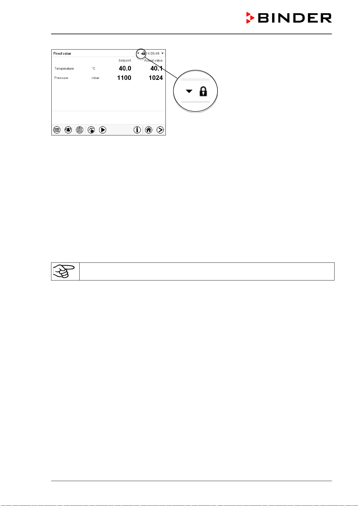
VDL (E3.1) 10/2020 Page 91/196
In the locked view the controller provides all display functions. No setting functions are available.
The setpoints are shaded (light grey) in normal display. Changing them by direct entry in the fixed value
operating mode is not possible. The functional icons for setpoint entry and program start in the footer are
without function.
After turning on the unit, user log-in is required to operate the controller (chap. 12.2).
Operation without user log-in / without password-protection
If the password function has been deactivated, after turning on the unit without user log-in there are those
controller functions available, which correspond to the highest authorization level without a password pro-
tection. There is no lock icon in the header.
9.7 Loading
Without technical ventilation the chamber must not be loaded with material containing sol-
vents.
The chamber cannot be loaded when turned off / in standby mode .
Before loading the material to be loaded, note:
When loading the chamber also in the context of intended use, an explosive mixture may form in the working
space. Therefore, a safety area of at least. 1 m in front of the oven must be considered.
• Ensure equipotential bonding. The accessible installation and operating surface of the equipment must
be conductive. This installation and operating surface must be connected with the vacuum drying oven
according to the grounding plan (Chap. 6.8).
• The personal protective equipment (PPE) of the operating personnel must be implemented ESD pro-
tected. This applies also to gloves.
• Activate the technical ventilation (extraction):
The operator shall provide active ventilation (technical ventilation according to country-specific regula-
tions (TRBS 2152 Part 2 for Germany) prior to commissioning of the chamber. It must include the entire
installation area of the vacuum drying oven. Loading must take place under technical ventilation in the
safety area in front of the oven.
• Introduce only those solvents for which the auto-ignition temperature and the maximum drying temper-
ature (safety temperature) have been determined and setting on the safety controller has been per-
formed.
Acc. to IEC 60079-0, only substances with an auto-ignition temperature above 200 °C / 392 °F may be
introduced into the chamber. This chamber is NOT suitable for drying substances with an auto-igni-
tion temperature below 200 °C.
VDL (E3.1) 10/2020 Page 92/196
DANGER
Explosion or implosion hazard and danger of poisoning by introduction of unsuita-
ble loading material.
Serious injury or death from burns and / or explosion pressure or by poisoning.
∅ Do NOT introduce any substance with an auto-ignition temperature below 200 °C /
392 °F into the chamber.
∅ Do NOT introduce any substance which is combustible or explosive at working temper-
ature into the chamber.
∅ Do NOT introduce energy sources such as batteries or lithium-ion batteries into the
chamber.
∅ Do NOT introduce any substance, which fall under the explosives law into the chamber
∅ Do NOT introduce any combustible dust into the chamber.
∅ Do NOT introduce any substance which could lead to release of toxic gases into the
chamber.
If the auto-ignition temperature of a solvent contained in the drying material is exceeded during the drying
process, there is an immediate risk of fire and explosion. Make sure that the auto-ignition temperature of a
solvent contained will NEVER be reached.
DANGER
Fire and explosion hazard when exceeding the auto-ignition temperature of the sol-
vent.
Serious injury or death from burns and / or explosion pressure.
Take the auto-ignition temperature from the safety specifications of the solvent. In the
case of solvent mixtures, use the lowest auto-ignition temperature.
Correctly set the maximum drying temperature (safety temperature) on the temperature
safety device according to the information panel “Temperature setting”.
Introduce measures to prevent mixing up the material to be dried.
Before starting a new drying process with a different auto-ignition temperature, check
the auto-ignition temperature with the safety specifications of the solvent.
If, during loading material containing solvents falls down, it is possible that the solvent or solvent vapors
will spread outside the loading area, e.g. to the side of or below the chamber. The chamber must be dis-
connected from the power immediately (pull out the power plug or operate e.g., a customer's emergency
stop switch).
The chamber is not to be installed and operated in potentially explosive areas.
DANGER
Explosion hazard due to explosive mixtures in the vicinity of the equipment.
Serious injury or death from burns and / or explosion pressure.
∅ Ensure that NO solvents or explosive solvent-air mixtures are located in the area
around the chamber.
Disconnect the chamber from the power immediately if there is explosive atmosphere in
the area around the chamber outside the indicated loading area.
VDL (E3.1) 10/2020 Page 93/196
9.8 Evacuation
Starting situation: The vacuum pump / vacuum system is connected and ready for operation.
Preparation:
• Make sure that the “Manual ventilation” plug (7) for emergency ventilationin case of a power failure,
which is located on the chamber rear, is closed
• Make sure that the pressure control is activated.
• Turn on the vacuum pump. The pump shall continue running during the entire drying procedure.
• Set the desired pressure set-point on the controller (chap. 10).
• Monitor the internal pressure on the controller display
As long as there is a vacuum, never try to open the oven by force.
9.9 Breaking the vacuum (flooding)
9.9.1 Ventilation after completing the drying procedure (flooding with ambient air or
inert gas)
The duration of the drying procedure can be determined via the pressure display on the controller. When
the decreasing pressure reaches the set-point value, the drying process is completed. If the drying moni-
toring (chap. 11.6) is activated, a corresponding message is displayed.
To break the vacuum (ventilation) after completing the drying procedure, set the desired pressure set-point
to atmospheric pressure (chap. 10). The ventilation valve opens, and ambient air or inert gas flow into the
inner chamber.
Regularly the universal connection for inert gas / ambient air “GAS/AIR” (4) is used for ventilation.
Chambers can be equipped as an option with an additional universal connection for inert gas / ambient air
“GAS/AIR2” (5), which can be used alternatively. To do this, the controller function “GAS/AIR 2” serves to
close the valve of the standard connection “GAS/AIR” (4). Then the valve of the optional connection
“GAS/AIR 2” (5) is used for ventilation (chap. 11.2). This allows convenient switching when both connec-
tions are used differently (e.g., for inert gas and ambient air).
Ambient air is sucked in through the universal connection for inert gas / ambient air (4) or (5). The ambient
air is introduced into the lower part of the rear panel of the inner chamber and is evenly distributed in the
inner chamber. This supply of ambient air by under-flooding prevents turbulence of pulverized drying ma-
terial.
Following ventilation, remove the loading material.
If no further drying process is to be carried out, switch the chamber to standby mode on the controller or
pull the mains plug to switch off the chamber completely.
9.9.2 Operation with inert gas
When operating the VDL vacuum drying oven with inert gas, correctly follow the technical ventilation
measures, as described in the DGUV guidelines 213-850 on safe working in laboratories, issued by the
employers’ liability insurance association (for Germany).
During operation with inert gas, the chamber is supplied with an oxygen displacing gas (e.g. N
2
). Inert gases
in high concentrations are hazardous to health. They are colorless and almost odorless and therefore prac-
tically imperceptible. Inhalation of inert gases can cause drowsiness up to respiratory arrest. When the O
2
content of the air decreases below 18%, there is risk of death from lack of oxygen. Any gas that might
escape has to be led out via good room ventilation or a suitable exhaust system.
VDL (E3.1) 10/2020 Page 94/196
DANGER
Risk of suffocation due to high concentration of inert gas.
Death by suffocation.
∅ Do NOT set up chambers in non-ventilated recesses.
Ensure technical ventilation measures.
Respect the relevant regulations for handling these gases.
When decommissioning the vacuum drying oven, shut off the inert gas supply.
Install a pressure reducer for inert gas operation. Set the pressure reducer to a pressure slightly above
ambient pressure. Ensure that the pressure reducer will open. Do not change this setting in order to avoid
perturbation inside the oven and release of big quantities of inert gas after flooding the VDL.
Following evacuation, an inert gas, e.g., nitrogen, is led into the inner chamber via the connection
“GAS/AIR” (4) or the optional connection “GAS/AIR 2” (5) until pressure compensation with the atmosphere
occurs. Depending on the individual application, you can perform a second evacuation and repeat the inert
gas flooding.
When the inert gas fine dosing valve is open, a maximum of approx. 0.6 m³/h gas flows into the inner
chamber. The introduction of inert gas by under-flooding in the lower region of the inner chamber rear wall
and the extraction at the inner chamber ceiling allow an effective inert gas flushing.
9.9.3 Ventilation / breaking the vacuum in case of a power failure
The emergency ventilation is intended for the case of a completed drying process
To be able to open the chamber in case of a power failure, remove the “Manual ventilation” plug (7) for
emergency ventilation, which is located on the chamber rear.
As long as there is a vacuum, never try to open the oven by force.
Make sure that the drying procedure is complete before breaking the vacuum. Otherwise, you
should wait for the power to return to continue the drying procedure.
DANGER
Explosion hazard through the formation of an explosive atmosphere in the pres-
ence of hot surfaces.
Serious injury or death from burns and / or explosion pressure.
∅ Do NOT remove the “Manual ventilation” plug, as long as the drying process is still run-
ning.
9.9.4 Ventilation before completing the drying procedure (flooding with ambient air or
inert gas)
If possible, avoid terminating the drying process. If it is nevertheless to be done, it is essential to observe
the following instructions!
Safety during the drying process: The vacuum during drying prevents the presence of an explosive
atmosphere in the interior of the chamber. At the start of the drying process, the heater is therefore only
released at a pressure of 100 mbar. In addition, the maximum temperature is limited so that, with correct
load, there is no risk of ignition from hot surfaces.
VDL (E3.1) 10/2020 Page 95/196
Error: If incorrect loading with an inadmissible solvent (auto-ignition temperature <200 ° C) has occurred,
proceed as follows
• Disconnect the power plug and turn off the pump.
• Let the chamber cool down to room temperature.
• Do NOT remove the “Manual ventilation” plug.
• Only ventilate when the interior temperature has cooled to room temperature. Only then open the door.
Hazard when opening the door after ventilation: After incorrect loading, open the door only when the
inner temperature has sunk to ambient temperature.
Prior to a termination of a not completed drying process make sure that the auto-ignition tem-
peratureof the solvent has been determined correctly, and that the drying temperature
reached far below this. In case of doubt, do not interrupt the drying process!
Proceeding to terminate the drying process:
• Set the temperature set-point to approx. ambient temperature
• Let the chamber cool down to ambient temperature
• Set the pressure set-point to approx. atmospheric pressure
DANGER
Explosion hazard through the formation of an explosive atmosphere in the presence
of hot surfaces after incorrect loading
Serious injury or death from burns and / or explosion pressure.
∅ Do NOT use ambient air to break the vacuum as long as the chamber is hot. Do NOT
remove the “Manual ventilation” plug as long as the drying process is still running.
Let the chamber cool down to room temperature before opening the door.
9.10 Unloading the loading material
Do not unload the loading material without technical ventilation.
Note the following points before unloading the loading material:
When unloading the loading material also in the context of intended use, an explosive mixture may form in
the working space. Therefore, a safety area of min. 1 m in front of the oven must be considered.
• Activate Standby mode on the controller before opening the door.
• Ensure equipotential bonding: The accessible installation and operating area in front of the equipment
must be conductive. This installation and operating area must be connected to the vacuum drying oven
and other equipment according to the grounding plan (chap. 6.8).
• Activate the technical ventilation (extraction):
The operator shall provide active extraction (technical ventilation according to country-specific regula-
tions – TRBS 2152 Part 2 for Germany) prior to commissioning the oven. Extraction must include the
entire installation area of the vacuum drying oven. Unloading the loading material must take place in the
safety area in front of the oven with technical ventilation.
• The personal protective equipment (PPE) of the operating personnel must be implemented
ESDprotected.
• Sweep the area for electrical equipment, preheating chamber, and controller housing at least 10
minutes with compressed air (recommended).
VDL (E3.1) 10/2020 Page 96/196
9.11 Removing the full condensate catchpot of the pump
Do not remove the full condensate catchpot of the pump without technical ventilation
Note the following points before removing the condensate catchpot:
When removing the condensate catchpot spilling of the solvent may occur.
• Ensure equipotential bonding:
The accessible installation and operation area of the equipment must be conductive. This area and the
vacuum pump must be connected with the vacuum drying oven according to the grounding plan (Chap.
6.8).
• Activate the technical ventilation (extraction):
The operator shall provide active extraction (technical ventilation according to country-specific regula-
tions – TRBS 2152 Part 2 for Germany) prior to manipulating the condensate catchpot of the pump.
Extraction must include the entire installation area of the VDL and the vacuum pump, especially the area
of the catchpot (when removing it) and the exhaust air of the vacuum pump. Removing the full conden-
sate catchpot must take place under technical ventilation.
• Use ESD protected personal protective equipment:
The personal protective equipment (PPE) of the operating personnel must be implemented ESD pro-
tected. This includes also gloves.
9.12 Preparing a new drying process
Before starting a new drying process with a different auto-ignition temperature, determine the auto-ignition
temperature of the solvent according to its safety data sheet. In the case of solvent mixtures, use the lowest
auto-ignition temperature.
Check all settings (drying temperature, pressure set-point and safety controller setting). If appropriate,
make sure that the new temperature set-point and safety controller value are entered on the controller.
With each change of the temperature set-point, observe the safety controller setting.
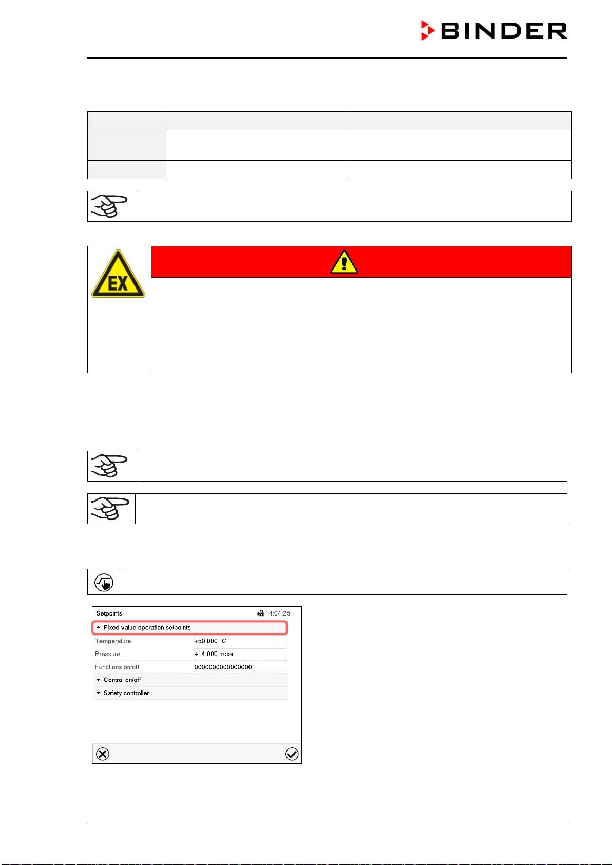
VDL (E3.1) 10/2020 Page 97/196
10. Set-point entry
Setting ranges Control ranges
Temperature
0.0 °C / 32 °F up to 110 ºC / 230 °F
10 °C / 18 °F above ambient temperature up to
110 ºC / 230 °F
Pressure 0 mbar up to 1100 mbar 0 mbar up to 1100 mbar
After starting the drying procedure, the heater is activated only when the pressure reaches or
falls below the required pressure threshold of 100 mbar.
Solvents and resulting vapors can ignite at excessive drying temperatures.
DANGER
Fire and explosion hazard when exceeding the auto-ignition temperature of the sol-
vent due to excess drying temperature.
Serious injury or death from burns and / or explosion pressure.
Make sure that only solvents with an auto-ignition temperature that is higher than
200 °C / 392 °F may be entered into the chamber. Check the auto-ignition temperature
with the safety specifications of the solvent. In the case of solvent mixtures, use the
auto-ignition temperature of the material with the lowest auto-ignition temperature.
In Fixed value operating mode, you can enter a temperature set-point, a pressure set-point, and the switch-
ing-state of special controller functions.
All settings made in Fixed value operating mode remain valid until the next manual change. They are saved
also when turning off the chamber or in case of toggling to Program Mode.
The values entered in Fixed value mode become valid again after the end of a program and
will then be targeted and equilibrated.
When operating without a vacuum by setting “Pressure control off” (chap. 11.5), the pressure
tolerance range function is automatically deactivated.
10.1 Set-point entry through the “Setpoints” menu
Press the Setpoint setting icon to access the “Setpoint” setting menu from Normal display.
“Setpoints” menu.
Select “Fixed value operation setpoints” to access the
individual parameters.
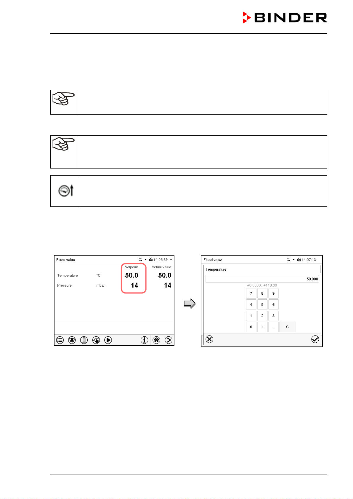
VDL (E3.1) 10/2020 Page 98/196
• Select the field “Temperature” and enter the desired temperature setpoint.
Confirm entry with Confirm icon.
• Select the field “Pressure” and enter the desired pressure setpoint.
Confirm entry with Confirm icon.
When entering a value outside the setting range, the message: “Value outside of limits! (Min:
xxx, Max: xxx)” appears (xxx is a wildcard for the limits of the respective parameter). Press
the Confirm icon and repeat the entry with a correct value.
After completing the settings, press the Confirm icon to take over the entries and exit the menu, or press
the Close icon to exit the menu without taking over the entries.
With set-point type “Limit”, adapt the safety controller (chap. 14.2) always when you changed
the temperature set-point. Set the safety controller set-point by approx. 5 °C above the con-
troller temperature set-point.
Recommended setting: Set-point type “Limit” with safety controller set-point 5 °C.
As long as the pressure threshold of 100 mbar has not yet been reached, the icon “Pressure
threshold not reached” in the screen header in Normal display. Press the flash icon next to
the information icon to access the corresponding text information “Pressure threshold not
reached” (Information messages, chap. 16.1)
10.2 Direct setpoint entry via Normal display
Alternatively you can also enter the setpoints directly via Normal display.
Normal display. Select the setpoint you want to
change.
Example: “Temperature” entry menu. Enter the
desired setpoint and confirm entry with Confirm
icon.
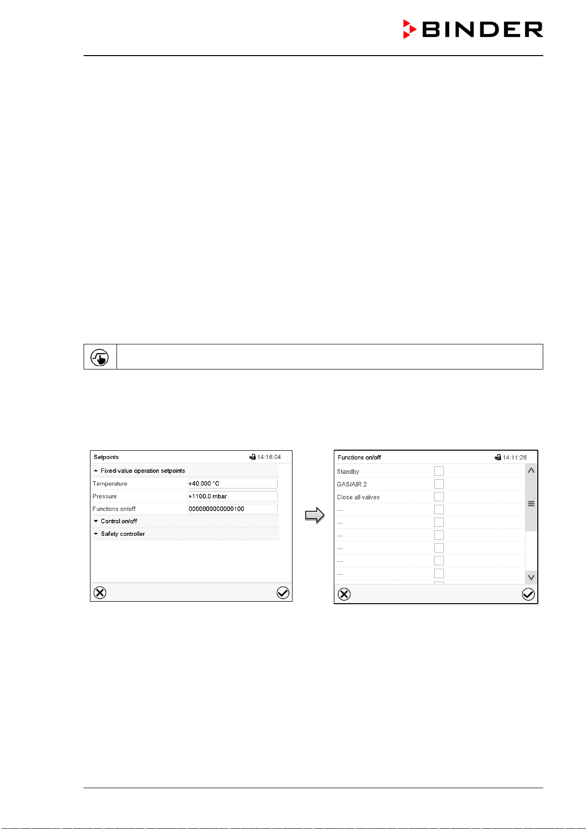
VDL (E3.1) 10/2020 Page 99/196
11. Setting special controller functions
You can set the following functions via the controller menu:
• Activate / deactivate the Standby mode (chap. 9.5)
• Use the optional connection “GAS/AIR2” (10) for ventilation (chap. 11.2)
• Close all existing fine dosing valves (chap. 11.3)
• Turning on / off temperature control (chap. 11.4)
• Turning on / off pressure control (chap. 11.5)
• Starting / terminating the drying monitoring (chap. 11.6)
11.1 Menu structure
11.1.1 “Functions on/off” menu
This chapter describes the setting with operating mode Fixed value operation. Settings for program opera-
tion are described in chap. 18.7.3 (time programs) and chap. 19.6.5 (week programs).
In the “Functions on/off” menu you can define the switching state of three controller functions.
Press the Setpoint setting icon to access the “Setpoint” setting menu from Normal display.
Path: Setpoint > Fixed value operation setpoints > Functions on/off
• Function “Standby“ (chap. 9.5)
• Function “GAS/AIR 2” (chap. 11.2)
• Function “Close all valves” (chap. 11.3)
“Setpoints” menu.
Select the field “Functions on/off”.
“Functions on/off” entry menu.
Mark / unmark the checkbox to activate / deac-
tivate the desired function and press the Con-
firm icon
The functions are displayed from right to left.
Activated function: switching status “1” (On)
Deactivated function: switching status “0” (Off)
Example:
Activated function “Standby” = 000000000000000
1
Deactivated function “Standby” = 000000000000000
0
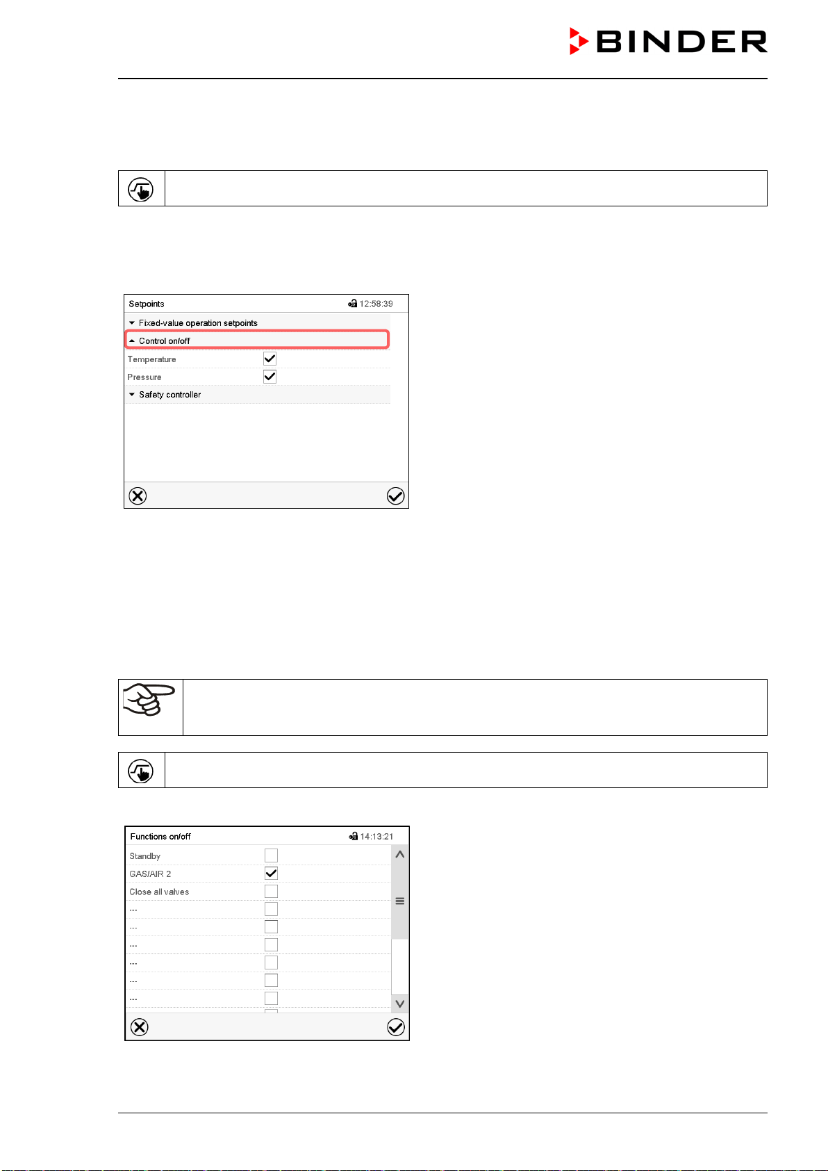
VDL (E3.1) 10/2020 Page 100/196
11.1.2 “Control on/off” menu
More functions are available via the “Control on/off” menu.
Press the Setpoint setting icon to access the “Setpoint” setting menu from Normal display.
Path: Setpoint > Control on/off
• Function “Temperature” (temperature control, chap. 11.4)
• Function “Pressure” (pressure control, chap. 11.5)
“Setpoints” menu.
Select the field “Control on/off”.
Mark / unmark the checkbox to activate / deactivate the
desired function and press the Confirm icon
11.2 Using the optional universal connection “GAS/AIR 2” for ventilation
Regularly the universal connection for inert gas / ambient air “GAS/AIR” (4) is used for ventilation.
The “GAS/AIR 2” function serves to close the valve of the standard connection “GAS/AIR” (4) and activate
the valve of the optional universal connection “GAS/AIR 2” (5), which is then used for ventilation
This allows convenient switching when both connections are used differently (e.g., for inert gas and ambient
air).
If you activate the “GAS/AIR 2” function on a chamber, which is NOT equipped with the op-
tional universal connection for inert gas / ambient air “GAS/AIR 2” (5), ventilation is no longer
possible!
Press the Setpoint setting icon to access the “Setpoint” setting menu from Normal display.
Path: Setpoint > Fixed value operation setpoints > Functions on/off
“Functions on/off” menu.
Mark the checkbox of the function “GAS/AIR 2” to acti-
vate it and press the Confirm icon.
In the “Setpoints” menu press again the Confirm icon.
The controller changes to Normal display.
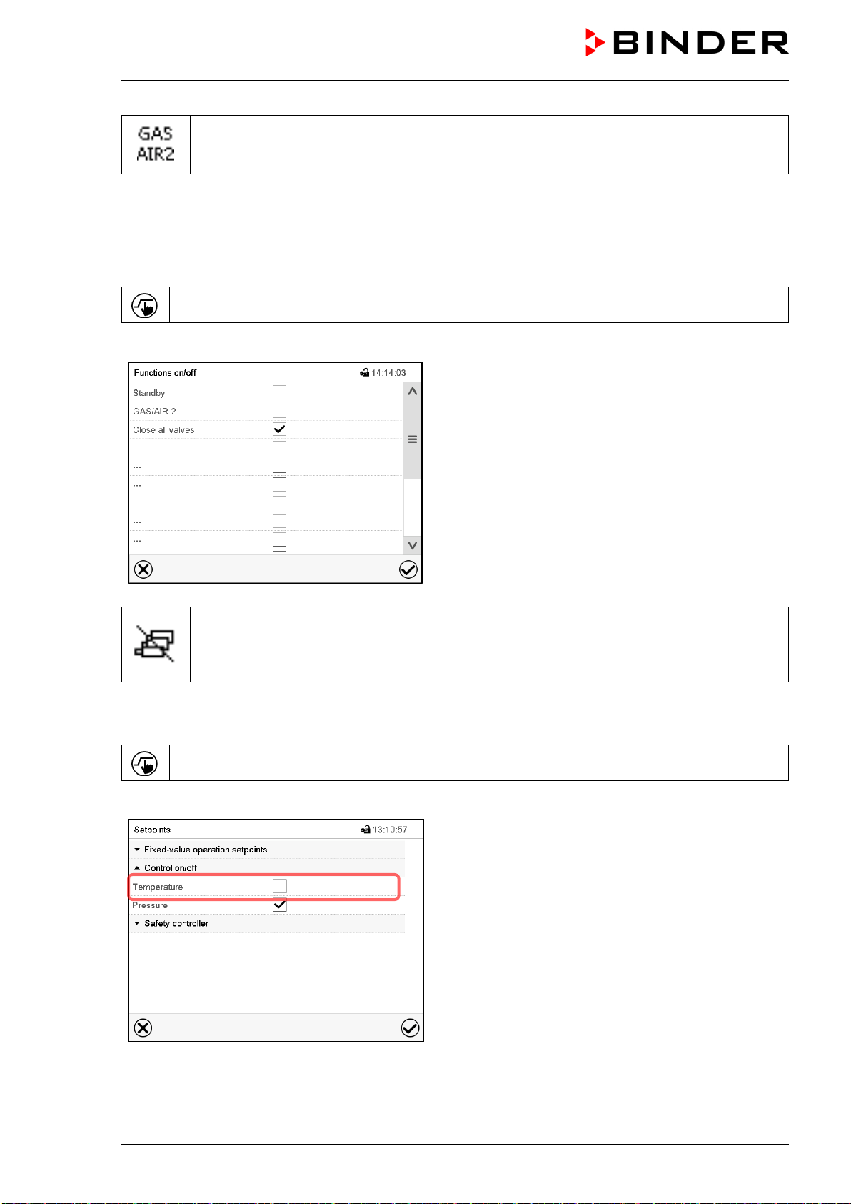
VDL (E3.1) 10/2020 Page 101/196
When the function “GAS/AIR 2” is activated, the “GAS/AIR 2” icon is displayed in the screen
header in Normal display. Press the flash icon next to the information icon to display the cor-
responding text information “GAS/AIR 2” (information messages, chap. 16.1)
11.3 Close all valves
Close all existing fine dosing valves
Press the Setpoint setting icon to access the “Setpoint” setting menu from Normal display.
Path: Setpoint > Fixed value operation setpoints > Functions on/off
“Functions on/off” menu.
Mark the checkbox of the function “Close all valves” to
activate it and press the Confirm icon.
In the “Setpoints” menu press again the Confirm icon.
The controller changes to Normal display.
When the function “Close all valves” is activated, the “All valves closed” icon is displayed in
the screen header in Normal display. Press the flash icon next to the information icon to dis-
play the corresponding text information “All valves are closed” (information messages, chap.
16.1)
11.4 Activating / deactivating temperature control
Press the Setpoint setting icon to access the “Setpoint” setting menu from Normal display.
Path: Setpoint > Control on/off
“Setpoints” menu.
Select the field “Control on/off” (example: deactivated
temperature control).
Mark / unmark the “Temperature” checkbox to activate /
deactivate temperature control and press the Confirm
icon.
• Checkbox marked: temperature control active
• Checkbox unmarked: temperature control deactivated
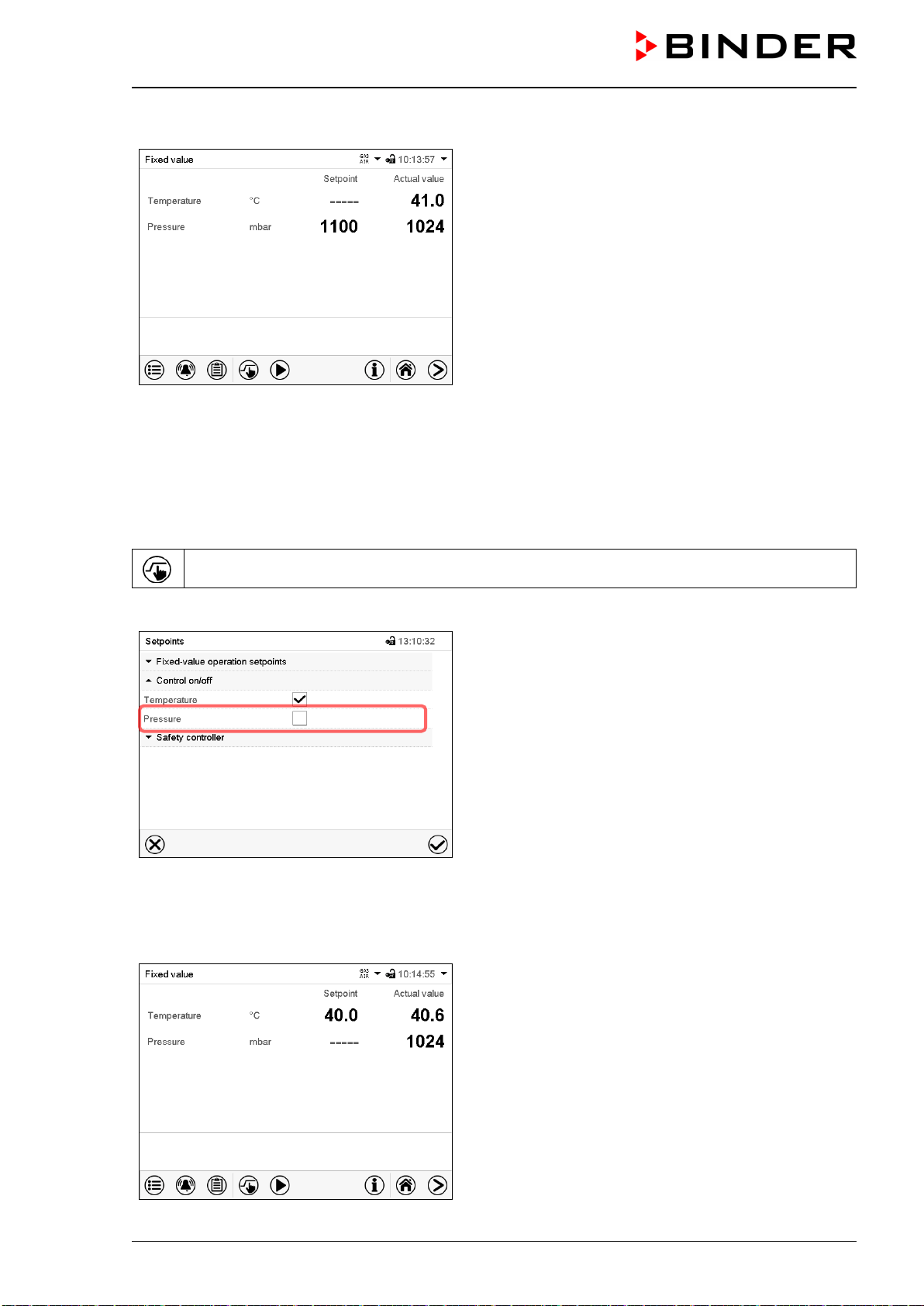
VDL (E3.1) 10/2020 Page 102/196
The actual temperature value continues to be displayed in Normal display:
Normal display with deactivated temperature control.
11.5 Activating / deactivating pressure control
When operating the chamber without a vacuum connection, you can deactivate pressure control with the
to avoid alarms of the pressure system. No pressure tolerance range alarms and no pressure alarm will be
emitted.
Evacuation and ventilation via the controller are then no longer possible. The chamber is ventilated.
Press the Setpoint setting icon to access the “Setpoint” setting menu from Normal display.
Path: Setpoint > Control on/off
“Setpoints” menu.
Select the field “Control on/off” (example: deactivated
pressure control).
Mark / unmark the “Pressure” checkbox to activate / de-
activate pressure control and press the Confirm icon
• Checkbox marked: pressure control active
• Checkbox unmarked: pressure control deactivated
The actual pressure value continues to be displayed in Normal display:
Normal display with deactivated pressure control.
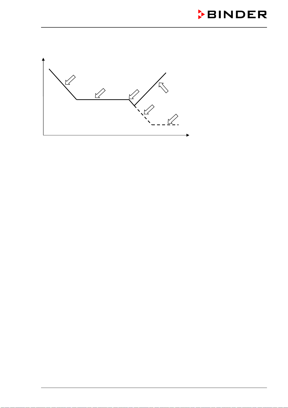
VDL (E3.1) 10/2020 Page 103/196
11.6 Drying monitoring
Pressure
Time
Figure 25: Schematic timing of the drying process and drying monitoring
Procedure:
• Enter the temperature set-point.
The previously entered pressure setpoint is not used with this function. It remains saved.
The drying monitoring uses a fixed minimum pressure setpoint.
• Start the drying monitoring: The vacuum pump is activated, the evacuation valve opens.
Starting from ambient pressure, the pressure starts to decrease.
• Depending on the vapor pressure of the solvent, a plateau phase is then reached
during which the
solvent vaporizes. The pressure remains almost constant.
• After the solvent is completely evaporated, drying is complete.
The pressure starts to decrease again
Without drying monitoring the pressure would now continue to decrease
, until the maximum final
vacuum is reached.
• The drying monitoring recognizes this second pressure drop. It turns off the pressure control. The cham-
ber will then be ventilated automatically
.
Prior to starting a new drying process, the pressure control must be activated again (chap. 11.4).
Notes:
If the drying monitoring is aborted during phase
or , the controller will take the current actual pressure
value as the pressure setpoint. This overwrites the previously entered pressure setpoint. It can be changed
manually at any time.
In processes with low temperatures < 40 °C or thermally poorly coupled items to be dried (e.g. drying of
powders), the drying monitoring may incorrectly identify the relevant parameters. In this case, please check
the process result and, if necessary, use a process not including this program for such processes.
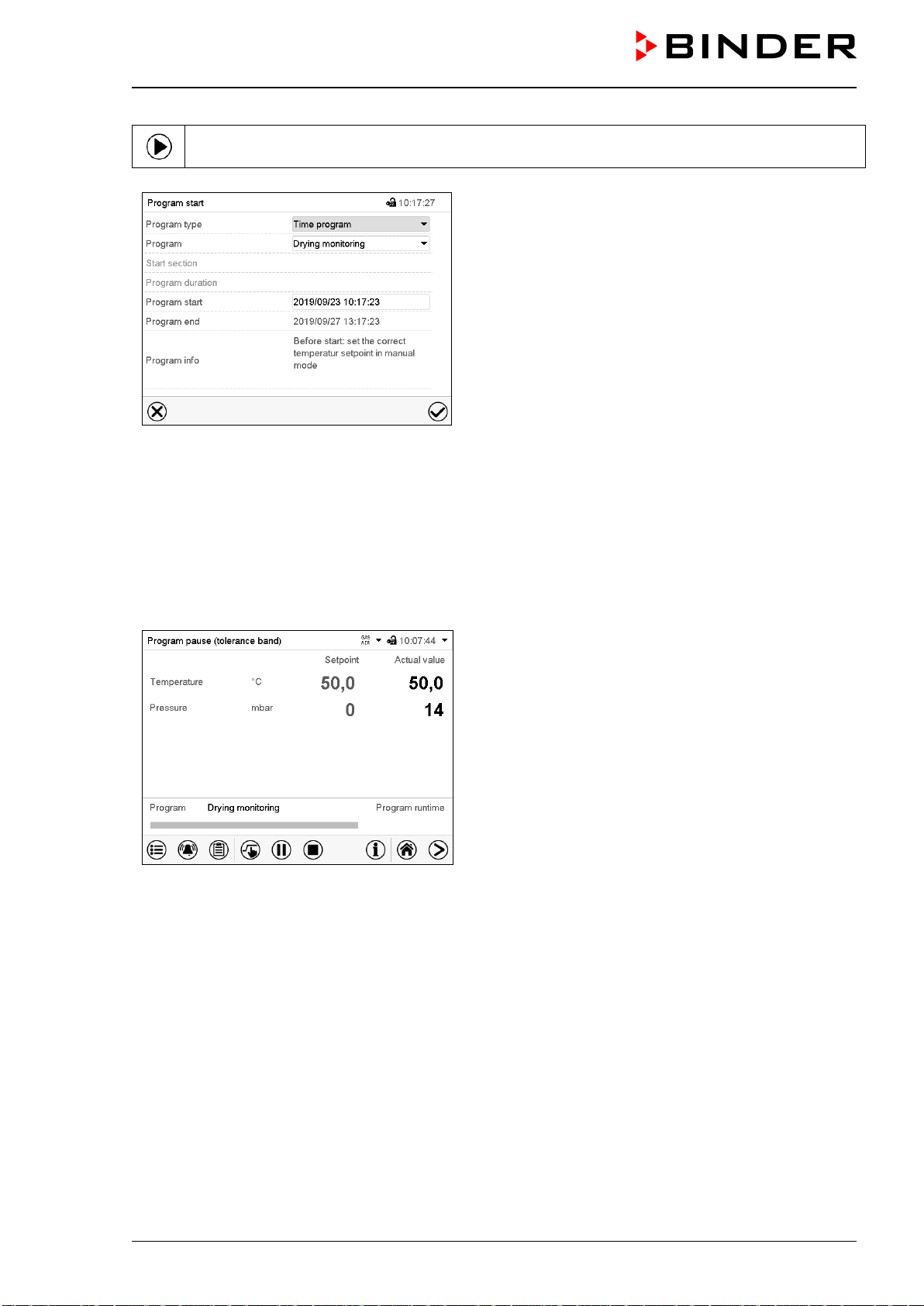
VDL (E3.1) 10/2020 Page 104/196
In Normal display press the Program start icon to access the “Program start” menu.
“Program start” menu with the selected Drying moni-
toring program.
• In the field “Program” select the setting “Drying monitoring” program.
• Select the field “Program start” and enter the desired program start time in the “Program start” entry
menu. Press the Confirm icon. The program delay time until program start begins. The program end is
calculated automatically.
After completing the settings, press the Confirm icon to take over the entries and exit the menu. The pro-
gram starts running.
If instead you press the Close icon to exit the menu without taking over the entries, the program will not
start.
Normal display. Information on the bottom of the
screen indicates the currently running program and the
time already passed. The grey bar shows how much
time of the whole time is elapsed.

VDL (E3.1) 10/2020 Page 105/196
12. Authorization levels and password protection
We recommend that you also assign a password to the "User" authorization level so that no
unauthorized person can use the chamber.
12.1 User management, authorization levels and password protection
The available functions depend on the current authorization level “Master”, “Service”, “Admin” or “User”.
The authorization levels are hierarchical: Every authorization includes all functions of the next lower level.
“Master” authorization level
• Highest authorization level, only for developers
• Extensive authorization for controller operation and configuration, outputs/inputs, alarm settings, param-
eter sets and operating ring display
• All passwords can be changed in the “log out” submenu (chap. 12.3).
“Service” authorization level
• Authorization level only for BINDER service
• Extensive authorization for controller operation and configuration, access to service data
• The passwords for “Service”, “Admin” and “User” authorization levels can be changed in the “log out”
submenu (chap. 12.3).
“Admin” authorization level
• Expert authorization level, for the administrator
• Authorization for controller configuration and network settings and for operating those controller func-
tions required for operating the chamber. Restricted access to service data.
• Password (factory setting): “2”.
• The passwords for “Admin” and “User” authorization levels can be changed in the “log out” submenu
(chap. 12.3).
“User” authorization level
• Standard authorization level for the chamber operator
• Authorization for operating the controller functions required for operating the chamber.
• No authorization for controller configuration and network settings. The “Settings” and “Service” sub-
menus of the main menu are not available.
• Password (factory setting): “1”
• The password for the “User” authorization level can be changed in the “log out” submenu (chap. 12.3).
As soon as a password has been assigned for an authorization level, the access to this level and the related
controller functions are only available after log-in with the appropriate password.
If for an authorization level no password is assigned, the related controller functions of this level are avail-
able for every user without login.
If passwords have been assigned for all authorization levels, access to the controller functions is locked
without login.
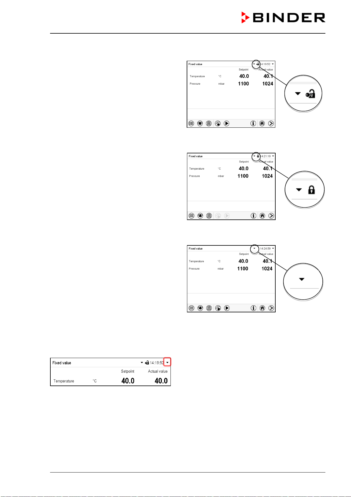
VDL (E3.1) 10/2020 Page 106/196
Operation after user login
At user login, the authorization level is selected
and confirmed by entering the respective pass-
word.
Following user login, controller operation is
available, recognizable by the open-lock icon in
the header. The available controller functions
correspond to the user’s authorization level.
Password protection activated for all levels: operation without user login is locked
If passwords have been assigned for all authori-
zation levels, the controller is locked without reg-
istration of a user.
As long as no user is registered, controller oper-
ation is locked, recognizable at the closed-lock
icon in the header. This requires that the user
management has been activated by the assign-
ment of passwords for the individual authoriza-
tion levels.
Password protection for at least one level deactivated: operation without user login is possible
If passwords have not been assigned for all au-
thorization levels, after turning on the chamber
there are those controller functions available,
which correspond to the highest authorization
level without password protection.
No lock icon is shown in the display header.
User login is neither required nor possible.
To activate the password protection and user
login, perform new password assignment (chap.
12.5.3).
Information window
To check the authorization level of the user currently logged-in, select in Normal display the arrow far right
in the display header.
The information window shows date and time, the controller’s free memory space and under “Authorization”
the authorization level of the current user.
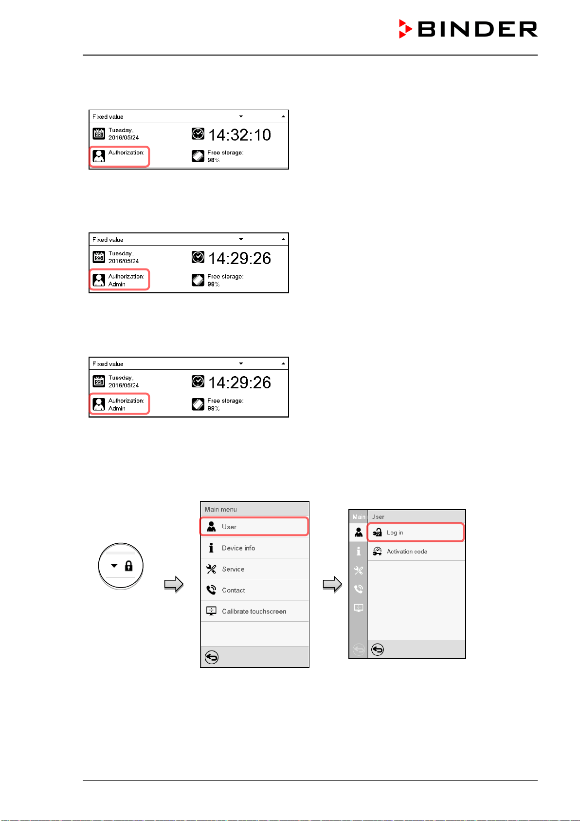
VDL (E3.1) 10/2020 Page 107/196
If passwords have been assigned for all authorization levels, a user without login (password entry) has no
authorization. There are only viewing functions available.
Display when all authorization levels are password
protected and no user has logged in:
No authorization level is displayed.
If passwords have been assigned only for some of the authorization levels, a user without login (password
entry) has access to the functions of the highest authorization level without password protection.
Display when only some of the authorization levels
are password protected (example: no protection for
the “User” and “Admin” levels) and no user has
logged in:
The user’s effective authorization (due to lack of
password protection) is shown.
Example: user with “Admin” authorization.
If passwords have been assigned for some or all of the authorization levels, user login (password entry)
provides the authorization for the corresponding password-protected level.
Display when at least some of the authorization levels
are password protected and a user has logged in.
The user’s authorization (by password entry) is
shown.
Example: user with “Admin” authorization.
12.2 Log in
Path: Main menu > User > Log in
Controller with-
out a user
logged-in
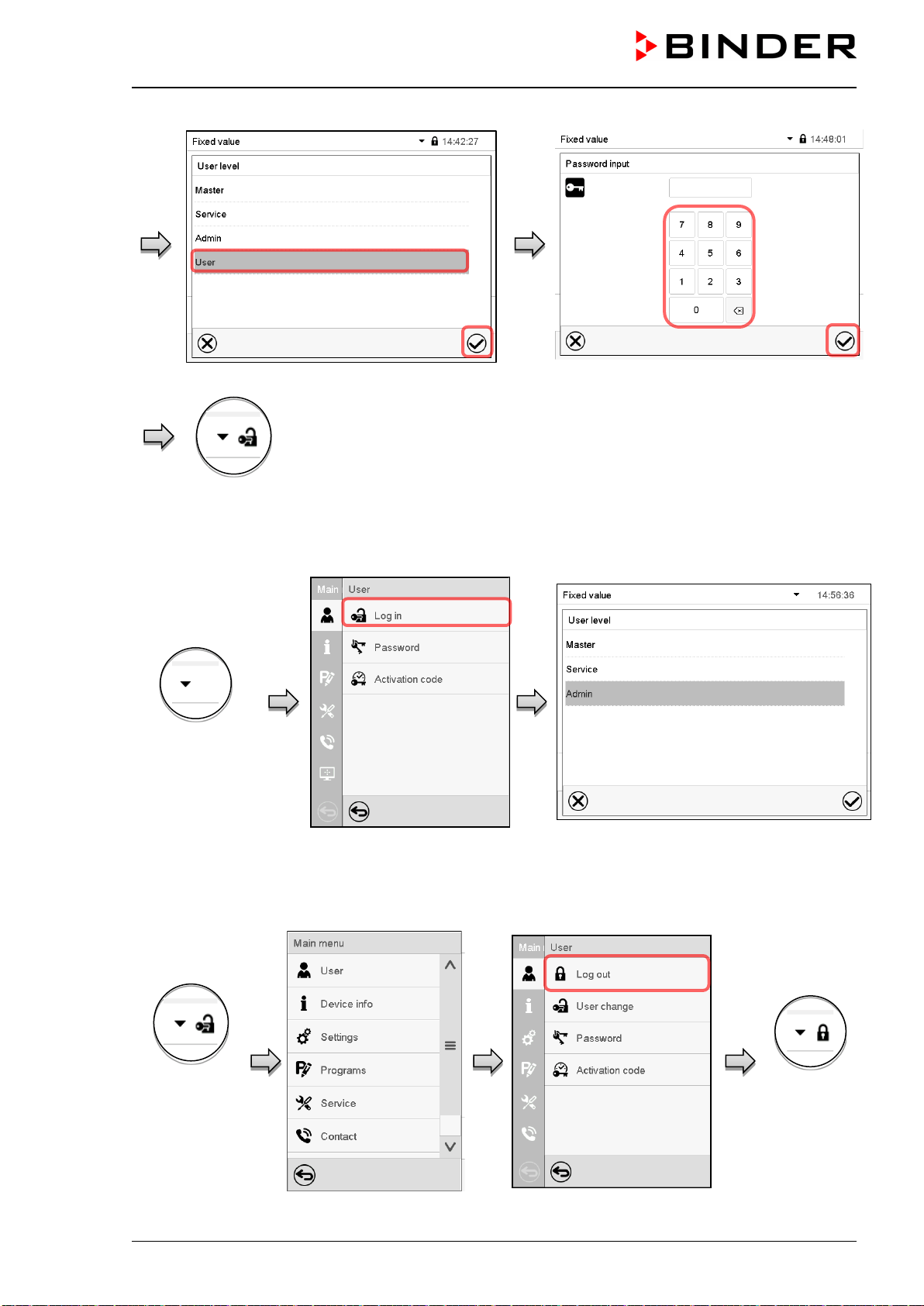
VDL (E3.1) 10/2020 Page 108/196
Selection of user type (example) All selection possibilities are password protected
Controller with logged-in user
After completing the settings, press the Confirm icon to take over the entries and exit the menu, or press
the Close icon to exit the menu without taking over the entries.
Controller with
deactivated
password
12.3 Log out
Path: Main menu > User > Log out
Controller with
logged-in user
(e.g. “Admin”
authorization)
Controller
without a user
logged-in
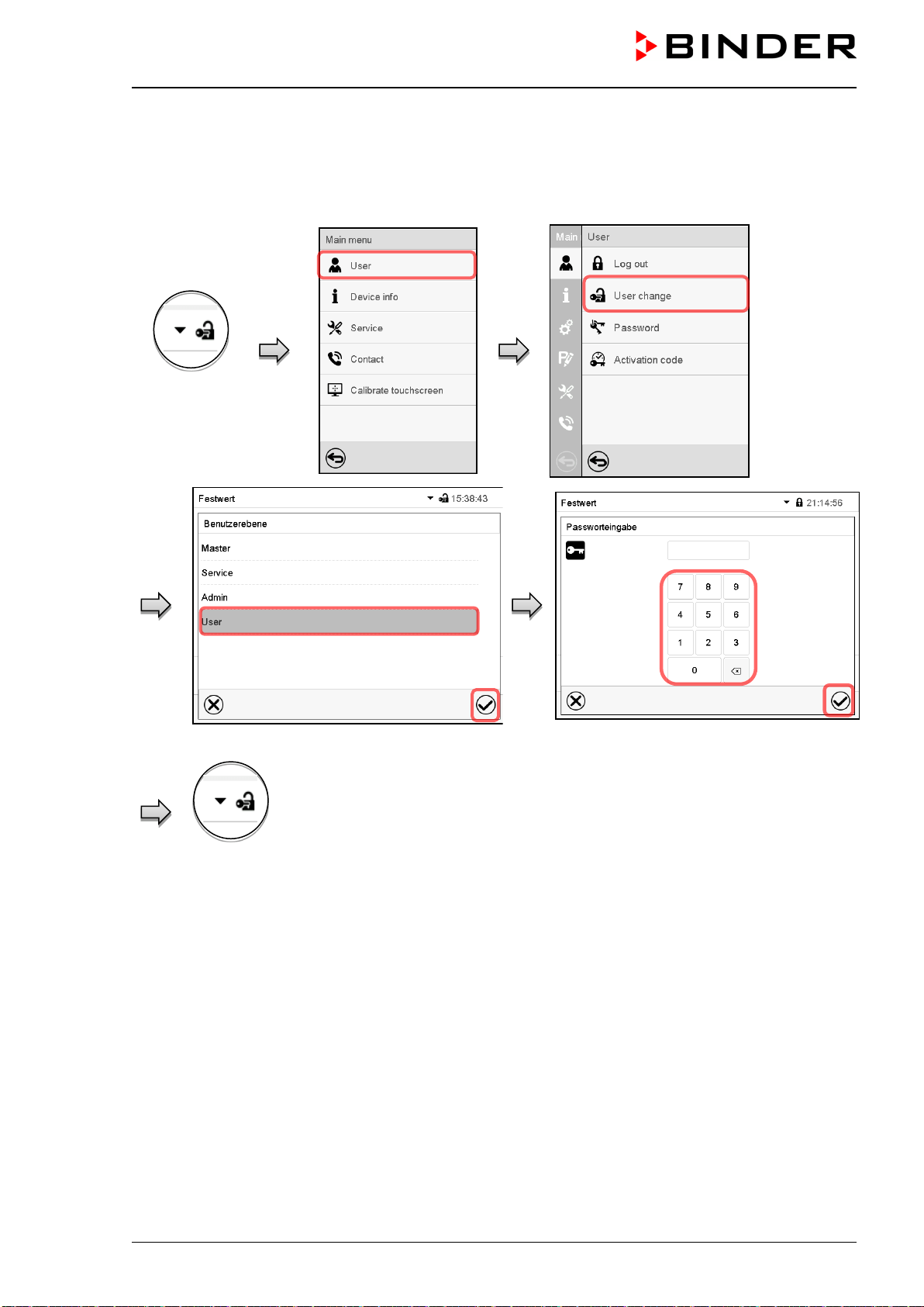
VDL (E3.1) 10/2020 Page 109/196
12.4 User change
If the password function has been deactivated (chap.12.5.2) this function is not available.
Path: Main menu > User > User change
Controller with
logged-in user
User selection (example) All selection possibilities are password protected
Controller with logged-
in user
12.5 Password assignment and password change
This function is not available for a user logged-in with “User” authorization.
12.5.1 Password change
A logged-in user can change the passwords of his current level and of the next lower level(s).
Example: A user with “Admin” authorization can change the passwords for the “Admin” and “User” author-
ization levels.
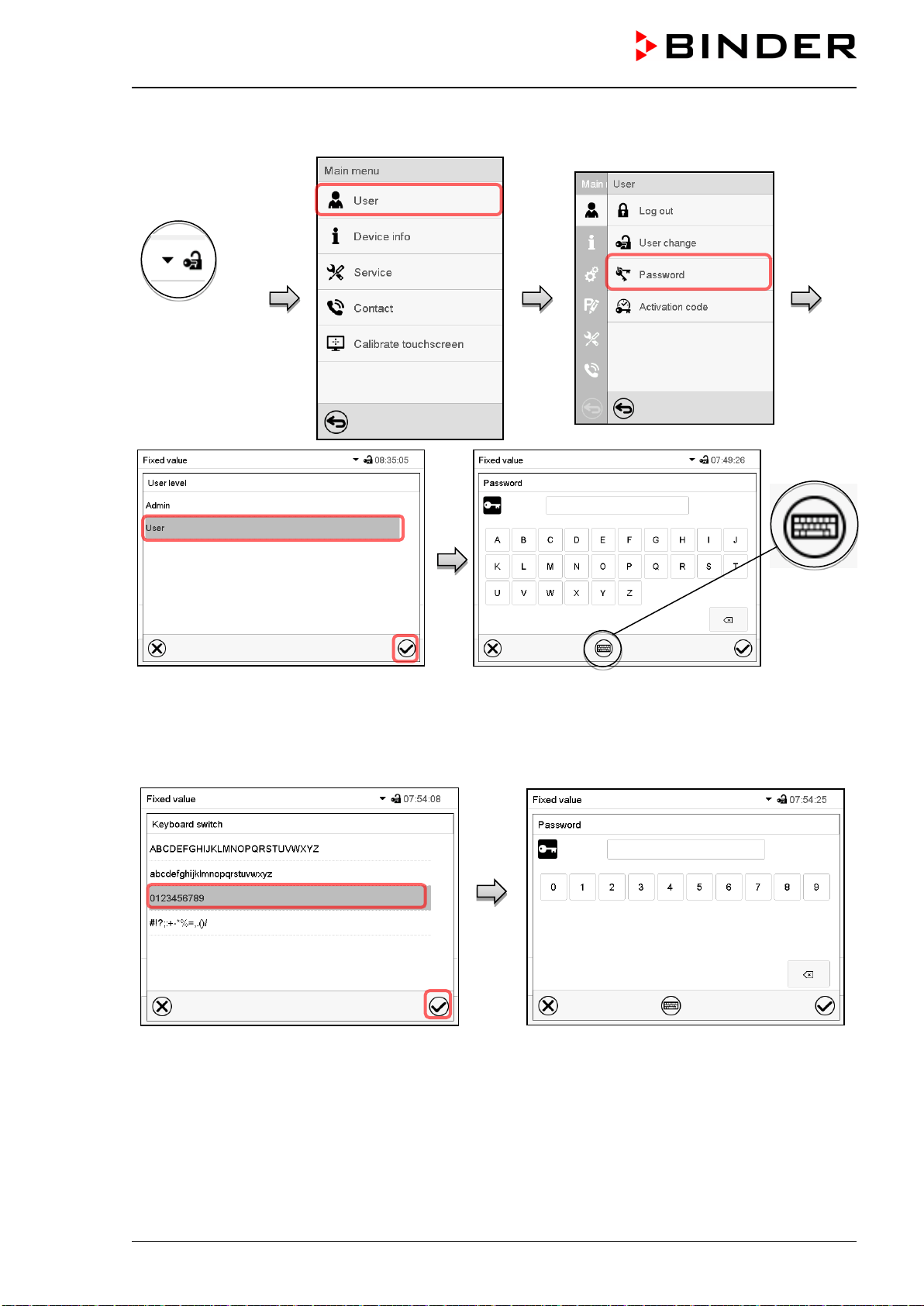
VDL (E3.1) 10/2020 Page 110/196
Path: Main menu > User > Password
User logged-in
with “Service” or
“Admin”
authorization
Selection of the authorization level
(example: view with “Admin” authorization)
Enter desired password. If desired, press the Change
keyboard icon to access other entry windows.
In the “Keyboard switch” window you can select different keyboards to enter uppercase and lowercase
letters, digits, and special characters. All types of characters can be combined within one single password.
Example: access the digit entry window
Entry of digits
To confirm the entry, press the Confirm icon.
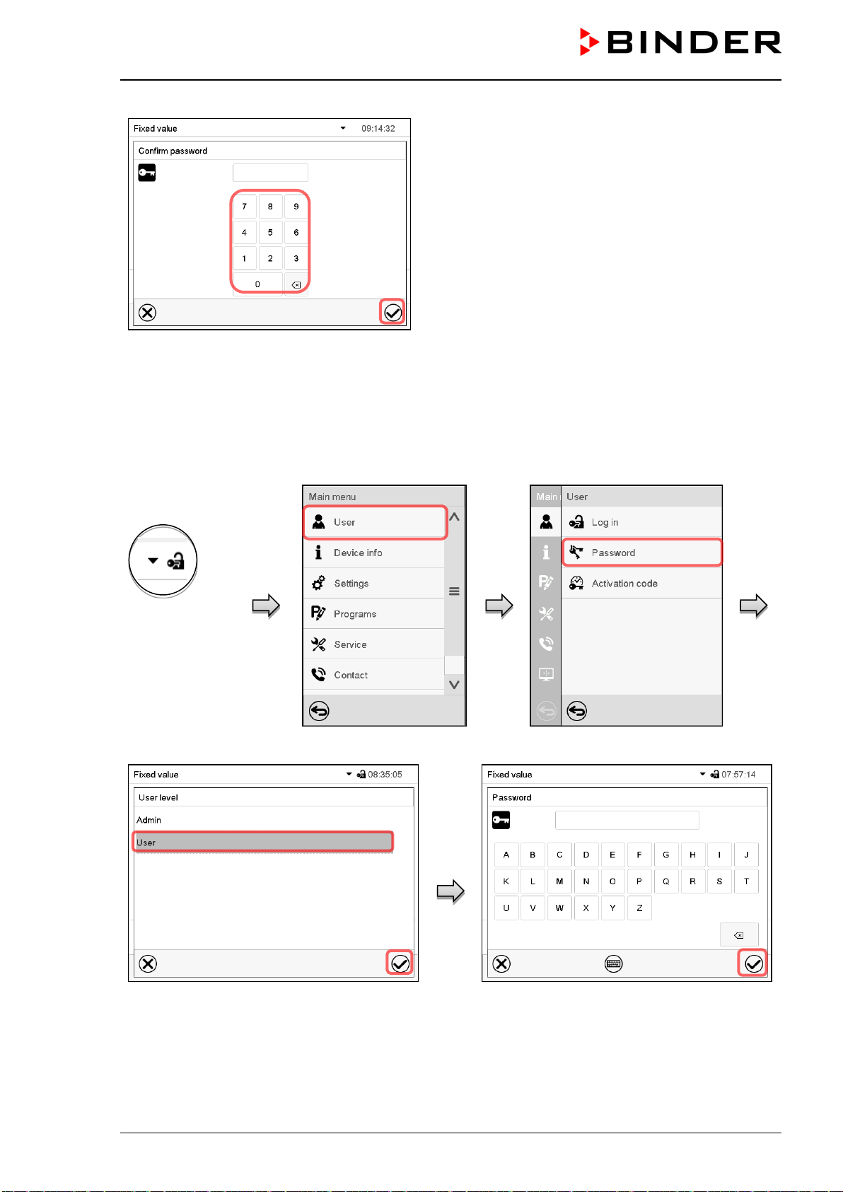
VDL (E3.1) 10/2020 Page 111/196
Repeat the password entry for confirmation (sample
picture). For each character of the password, the re-
quired keyboard appears automatically.
Then press the Confirm icon.
12.5.2 Deleting the password for an individual authorization level
A user logged-in with “Service” or “Admin” authorization can delete the passwords of his current level and
of the next lower level(s). To do this no password is entered during a password change.
Path: Main menu > User > Password
Controller with
logged-in user
(e.g. with “Ad-
min” authoriza-
tion)
Select the authorization level for which the
password shall be deleted.
Do NOT enter anything in the “Password”
screen. Press the Confirm icon.
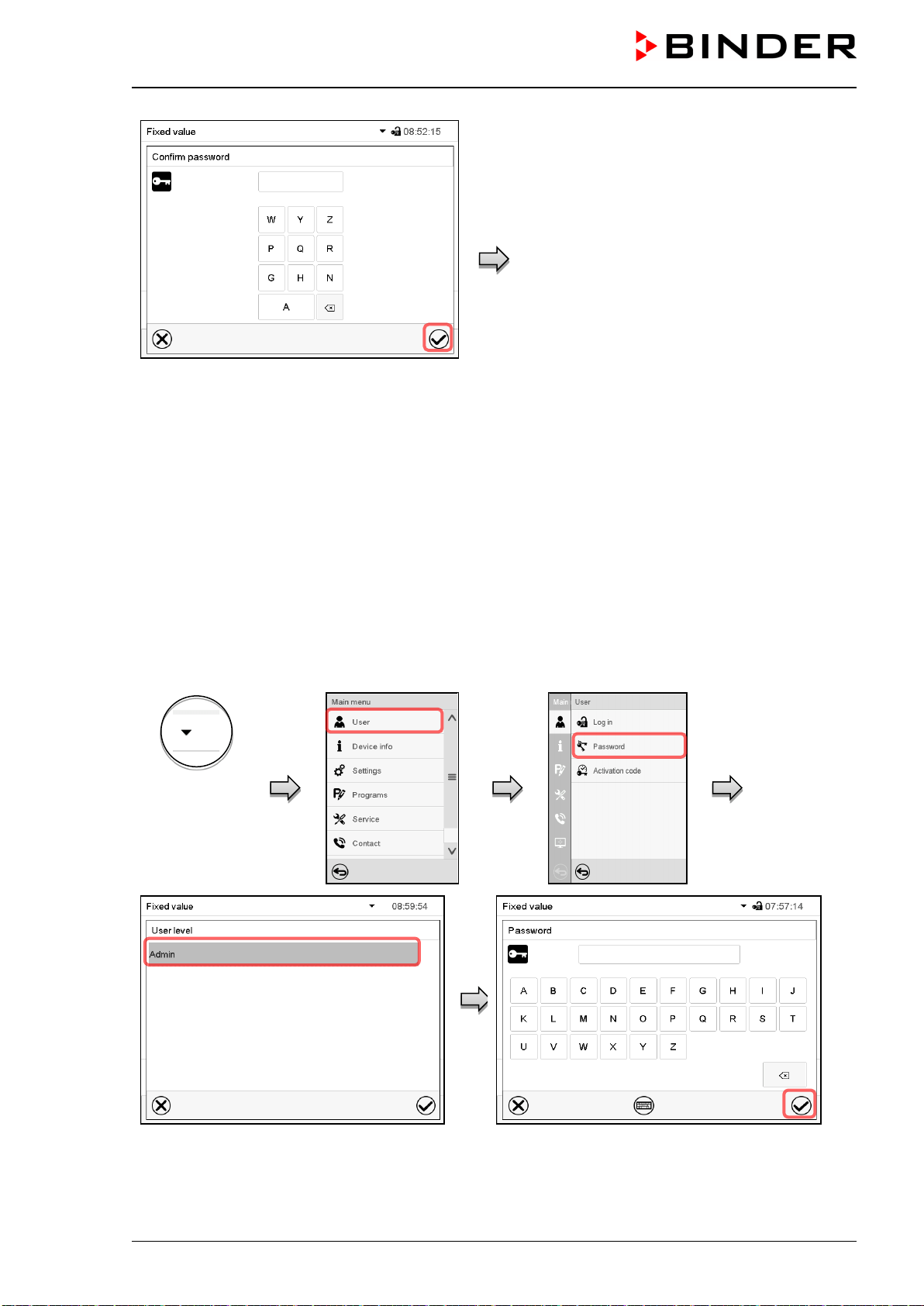
VDL (E3.1) 10/2020 Page 112/196
Do NOT enter anything in the “Confirm
password” screen. Press the Confirm icon.
The password is deleted.
12.5.3 New password assignment for “service” or “admin” authorization level when the
password function was deactivated
If the password protection for an authorization level has been deactivated, i.e., no password is assigned,
no login for this level is possible. Therefore, access to this authorization level is available without login.
If the password for the “Service” or “Admin” authorization has been deleted (chap. 12.5.2), a new password
can be assigned for the current level and the next lower level(s) without user login.
Example: The password for the “Admin” authorization level was deleted, therefore every user without login
has full access to the functions of the “Admin” authorization level. If access to this level shall become
password protected again, the user can assign a new password for the “Admin” authorization level with the
“Password” function.
Path: Main menu > User > Password
Controller with
deactivated
password for
“Service” or
“Admin” authori-
zation
Select the authorization level, for which you
want to assign a password.
(Example: “Admin” authorization)
Enter the desired password. If desired, press the
Change keyboard icon to access other entry win-
dows.
To confirm the entry, press the Confirm icon.
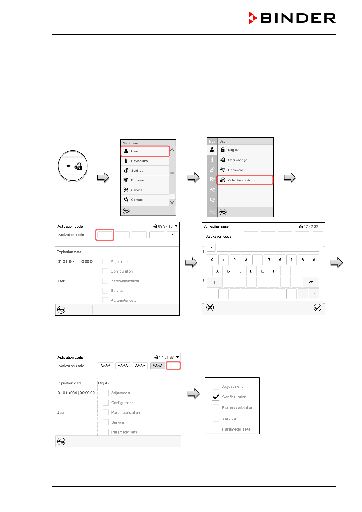
VDL (E3.1) 10/2020 Page 113/196
Repeat the password entry for confirmation. For each character of the password, the required keyboard
appears automatically. Then press the Confirm icon.
12.6 Activation code
Certain functions of the controller can be unlocked with a previously generated activation code.
The activation code enables access to functions available only in the “Service” authorization level by users
without a “Service” authorization. Such functions include e.g., adjustment or extended configurations.
The activation code is available in authorization levels.
Path: Main menu > User> Activation code
Controller
with logged-
in user
Activation code menu.
Select the first of the four entry fields.
Activation code entry window.
Enter the first four characters of the activation
code and press the Confirm icon.
Select the next of the four entry fields and proceed accordingly until the entire code has been entered.
“Activation code” menu with entered code (sam-
ple view). Press OK to take over the entry.
The available functions are indicated by
marked checkboxes.
Example: Extended configurations available.
Under “Expiration date” the date of expiry of
the code is displayed.
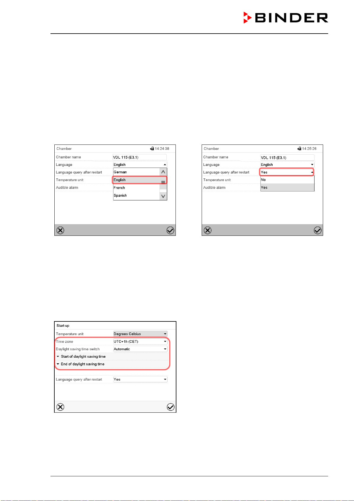
VDL (E3.1) 10/2020 Page 114/196
13. General controller settings and information
Most of the general settings can be accessed in the “Settings” submenu, which is available for users with
“Service” or “Admin” authorization level. It serves to enter date and time, select the language for the con-
troller menus and the desired temperature unit and to configure the controller’s communication functions.
13.1 Selecting the controller’s menu language
The MB2 program controller communicates by a menu guide using real words in German, English, French,
Spanish, and Italian.
Path: Main menu > Settings > Chamber
“Chamber” submenu.
Select the desired language.
“Chamber” submenu.
Select if there shall be a language query after
restarting the chamber and press the Confirm
icon.
Return to Normal display with the Back icon to take over the entries.
13.2 Setting date and time
Following start-up of the chamber after language selection:
Select the time zone and configure the day-
light-saving time switch.
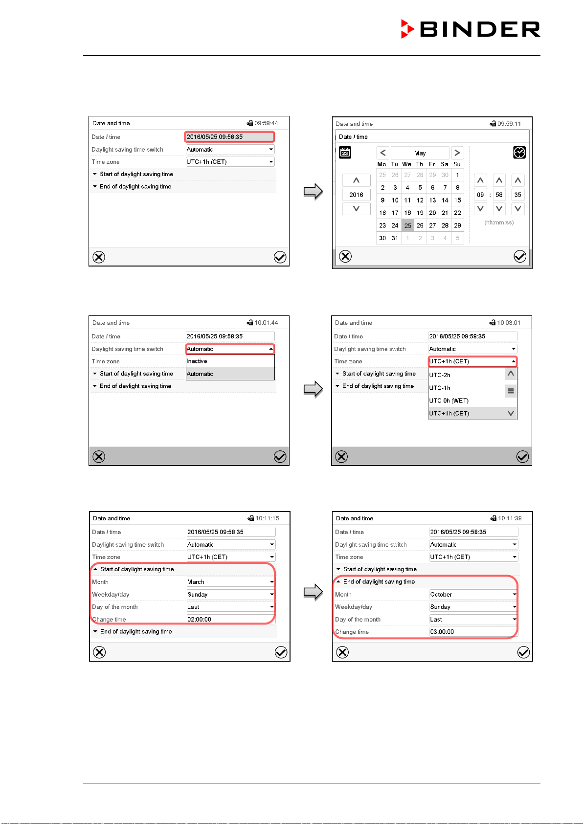
VDL (E3.1) 10/2020 Page 115/196
Or later:
Path: Main menu > Settings > Date and time
“Date and time” submenu.
Select the field “Date / time”.
“Date / time” entry menu.
Enter date and time and press the Confirm
icon.
“Date and time” submenu.
In the field “Daylight saving time switch” select
the desired setting “Automatic” or “Inactive”.
“Date and time” submenu.
Select the desired time zone and press the
Confirm icon.
“Date and time” submenu.
Select the desired start of the daylight saving
time.
“Date and time” submenu.
Select the desired end of the daylight saving
time and press the Confirm icon.
After completing the settings, press the Confirm icon to take over the entries and exit the menu, or press
the Close icon to exit the menu without taking over the entries.
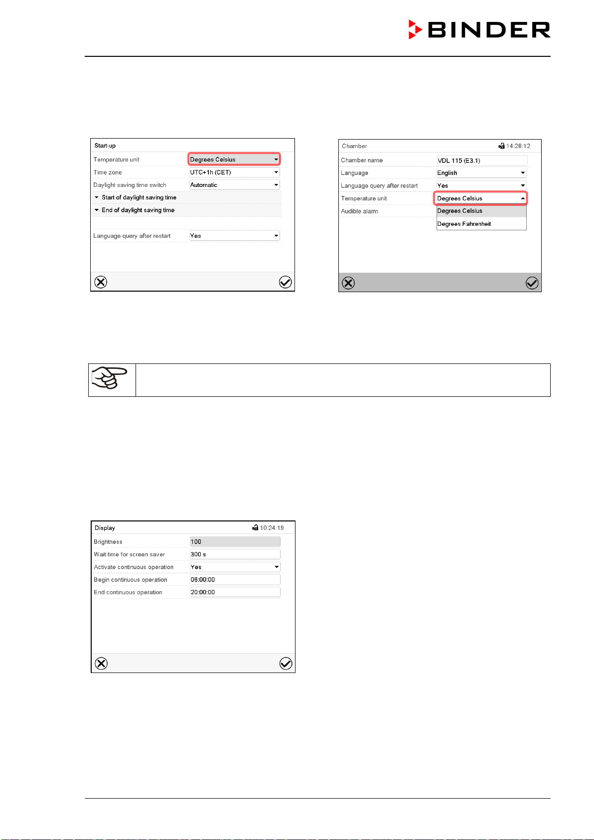
VDL (E3.1) 10/2020 Page 116/196
13.3 Selecting the temperature unit
Following start-up of the chamber:
Or later:
Path: Main menu > Settings > Chamber
Select the desired temperature unit and press
the Confirm icon.
Change of the temperature unit between °C and °F.
If the unit is changed, all values are converted accordingly
C = degree Celsius
F= degree Fahrenheit
0 °C = 31°F
100 °C = 212°F
Conversion:
[value in °F] = [value in °C] ∗ 1,8 + 32
13.4 Display configuration
13.4.1 Adapting the display parameters
This function serves to configure parameters like display brightness and operating times.
Path: Main menu > Settings > Display > Display
“Display” submenu.
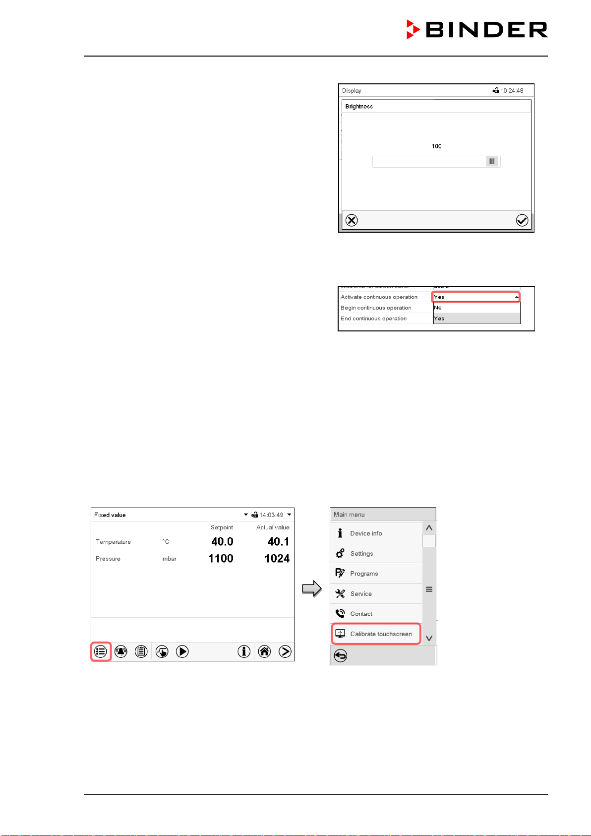
VDL (E3.1) 10/2020 Page 117/196
• Select the field “Brightness”.
Move the grey slide to the left or right to define the
brightness of the display
• left = darker (minimum value: 0)
• right = brighter (maximum value: 100)
Press the Confirm icon.
• Select the field “Wait time for screen saver” and enter the desired waiting time for the screen saver in
seconds. Setting range: 10 sec up to 32767 sec. During the waiting time the display is off. Confirm entry
with Confirm icon.
• In the field “Activate continuous operation” select the
desired setting “Yes” or “No”.
• Select the field “Begin continuous operation” (possible only if continuous operation is activated) and
enter the time with the arrow keys. Confirm entry with Confirm icon.
• Select the field “End continuous operation. (only possible if continuous operation is activated) and enter
the time with the arrow keys. Confirm entry with Confirm icon.
After completing the settings, press the Confirm icon to take over the entries and exit the menu, or press
the Close icon to exit the menu without taking over the entries.
13.4.2 Touchscreen calibration
This function serves to optimize the display for the user’s individual angular perspective.
Path: Main menu > Calibrate touchscreen
Normal display.
Select “Calibrate touchscreen” and follow the instructions on the display.
You need to touch all four corners of the touchscreen to calibrate it. Appropriate boxes appear successively
in each corner.
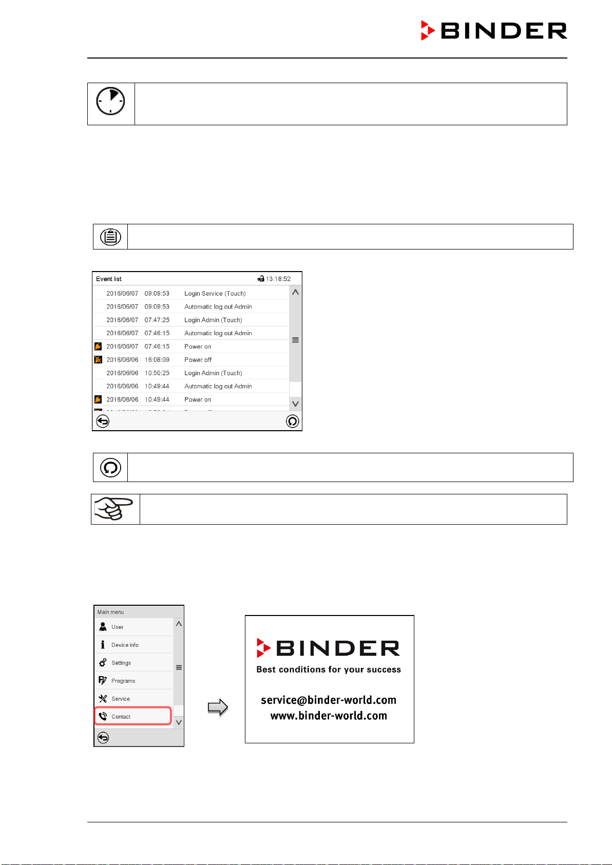
VDL (E3.1) 10/2020 Page 118/196
The waiting icon shows how much time there is left to touch the currently activated box. If
the box is not touched withing this period, calibration is aborted and the display changes to
Normal display.
After completing the calibration, i.e., touching all four boxes, the display changes to Normal display.
13.5 Event list
The “Event list” displays status information and errors of the current day. It enables to view the last 100
events or defective conditions of the chamber.
Press the Event list icon to access the event list from Normal display.
Event list
Press the Update icon to update the event list.
Attention: Following a modification of the language setting (chap. 13.1) or the storage inter-
val of the chart recorder (chap. 22.2) the Event list is cleared.
13.6 Service contact page
Path: Main menu > Contact
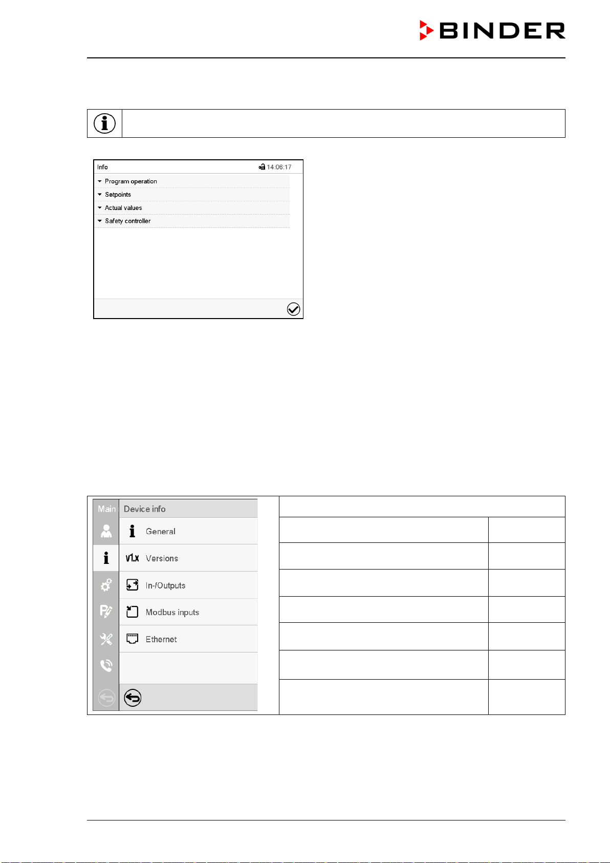
VDL (E3.1) 10/2020 Page 119/196
13.7 Current operating parameters
Press the Information icon to access the “Info” menu from Normal display.
“Info” menu.
Select the desired information.
• Select “Program operation” to see information on a currently running program.
• Select “Setpoints“ to see information on the entered setpoints and operation lines.
• Select “Actual values” to see information on the current actual values.
• Select “Safety controller” to see information on the safety controller status.
13.8 Technical chamber information
Path: Main menu > Device info
Chamber name and setup
Versions of CPU, I/O module and safety
controller
for BINDER
Service
Information on digital and analog inputs
and outputs and phase angle outputs
for BINDER
Service
Information on modbus analog and digital
inputs
for BINDER
Service
Information on Ethernet connection, MAC
address display
chap. 20.1
Back to main menu
VDL (E3.1) 10/2020 Page 120/196
14. Temperature safety devices
14.1 Safety temperature limiter (TL) class 2
The safety temperature limiter (TL) serves to protect the vacuum drying oven, its environment and loading
material against exceeding the permitted temperature. It has a fixed switching threshold and prevents ex-
ceeding the maximum surface temperature of the inner chamber of 160 °C in the event of a fault. If this
temperature is exceeded, the heater turns off. The TL protects the VDL vacuum drying oven, its environ-
ment and the loading material against impermissible excess temperatures and prevents exceeding the
maximum drying temperature in case of a fault.
The safety temperature limiter (TL) provides temperature monitoring through a thermal switch (bimetal
switch). If the permissible temperature is exceeded, the heating is switched off and an additional self-hold-
ing circuit is activated, which is only reset when the power plug is removed and reconnected. This prevents
the heating from being automatically switched on again. When the TL is triggered, an alarm message is
displayed on the controller. An annual function check by the operator is recommended, for this a controller
test routine is provided (chap. 16.5).
The safety temperature limiter (TL) provides ignition source monitoring . For further information of its func-
tion as part of the manufacturer's safety plan, please refer to chap. 3.1.
14.2 Overtemperature safety controller class 2
The chambers are regularly equipped with an electronic overtemperature safety controller (temperature
safety device class 2 – temperature limiter) acc. to DIN 12880:2007). The safety controller protects the
chamber, its environment and the charging material against exceeding the maximum permissible temper-
ature. The safety device class 2 is electrically independent of the temperature controller and turns off the
chamber permanently.
In the event of a fault in the temperature controller, the safety controller turns off the vacuum drying oven
permanently, i.e. until manual alarm reset. This condition (state of alarm) is indicated visually and addition-
ally with an audible alert if the buzzer is enabled (chap. 16.4). You can turn off the buzzer with the OK
button / Confirm icon. The alarm persists until the chamber cools down below the configured safety con-
troller value.
Please observe the DGUV guidelines 213-850 on safe working in laboratories, issued by the employers’
liability insurance association (for Germany).
Check the setting regularly and adjust it following changes of the set-point or charge.
The temperature safety device only activates after the set-point has been reached once.
14.2.1 Safety controller mode
You can set the safety controller mode to “Limit” or “Offset”.
• Limit: Limit value, absolute maximum permitted temperature value
This setting offers high safety as a defined temperature limit will not be exceeded. It is important to adapt
the safety controller value after each modification of the temperature set-point. Otherwise, the limit could
be too high to ensure efficient protection, or, in the opposite case, it could prevent the controller from
reaching an entered set-point outside the limit range.
• Offset: Offset value, maximum overtemperature above any active temperature set point. The resulting
maximum temperature changes internally and automatically with every temperature set-point change.
This setting is recommended for program operation. It is important to check the safety controller set-
point and safety controller mode occasionally, as it does not offer a fix, independent limit temperature
value, which would never be exceeded.
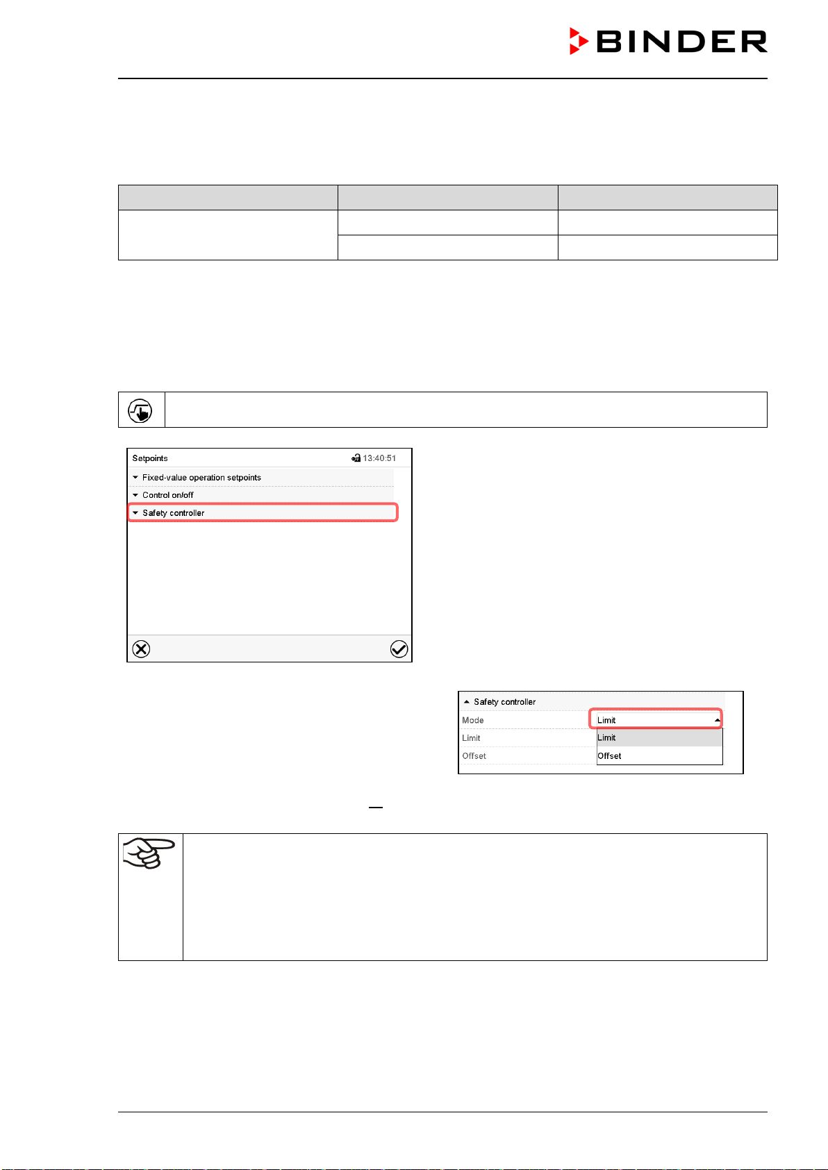
VDL (E3.1) 10/2020 Page 121/196
Example:
Desired temperature value: 40 °C, desired safety controller value: 45 °C.
Possible settings for this example:
Temperature set point Safety controller mode Safety controller value
40 °C
Limit Limit value 45 °C
Offset Offset value 5 °C
Recommended setting: Safety controller mode “Limit”, safety controller value by approx. 5 °C above the
temperature set-point.
14.2.2 Setting the safety controller
Press the Setpoint setting icon to access the “Setpoint” setting menu from Normal display.
“Setpoints” menu.
Select the field “Safety controller” to access the
settings.
• In the field “Mode” select the desired setting
“Limit” or “Offset”.
• Select the corresponding field “Limit” or “Offset” according to the selected mode and enter the desired
safety controller setpoint. Confirm entry with Confirm icon.
Regularly check the safety controller setting for set-point type “Limit” or “Offset”
• in Fixed value operating mode according to the entered set-point temperature value
• in progr
am mode according to the highest temperature value of the selected temperature
program
Recommended setting: Set the safety controller set-point by approx. 5 °C above the desired
temperature set-point.
After completing the settings, press the Confirm icon to take over the entries and exit the menu, or press
the Close icon to exit the menu without taking over the entries.
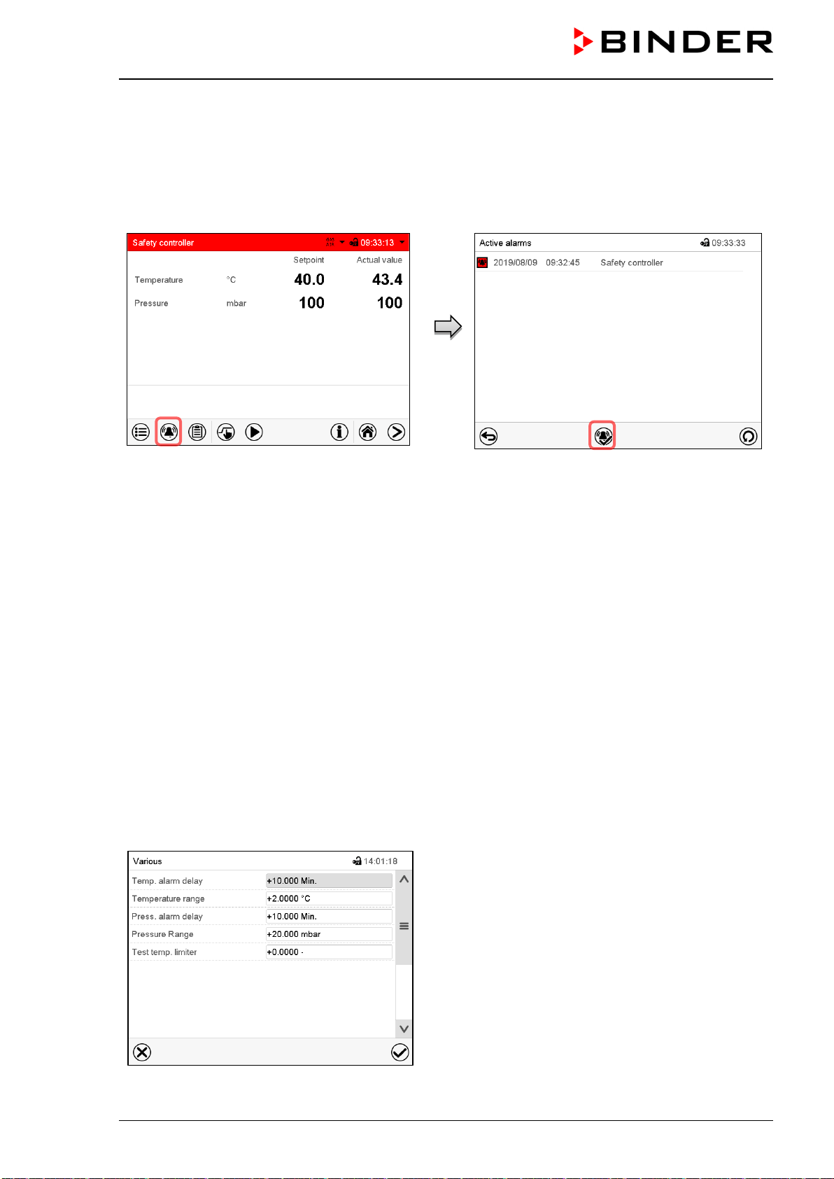
VDL (E3.1) 10/2020 Page 122/196
14.2.3 Message and measures in the state of alarm
The state of alarm is indicated visually and additionally with an audible alert if the buzzer is enabled (chap.
16.4).
The alarm remains active until it is acknowledged on the controller and the inner temperature falls below
the set safety controller setpoint. Then the heating is released again.
Normal display with safety controller alarm.
Press the Alarm icon
List of active alarms.
Press the Reset alarm icon.
14.2.4 Function check
Check the safety controller at appropriate intervals for its functionality. It is recommended that the author-
ized operating personnel should perform such a check, e.g., before starting a longer work procedure.
15. Tolerance range settings
In this menu you can define for temperature and pressure the deviation between the actual value and
setpoint, which that shall cause a tolerance range alarm. The entered value defines the limit of permitted
deviations from the set-point (exceeding and falling below). Reaching this limit triggers tolerance alarm.
In addition, you can specify delay times for these alarms.
This function only activates after the set-point has been reached once.
15.1 Setting the alarm delay times and the tolerance ranges
Path: Main menu > Settings > Various
Submenu “Various”.
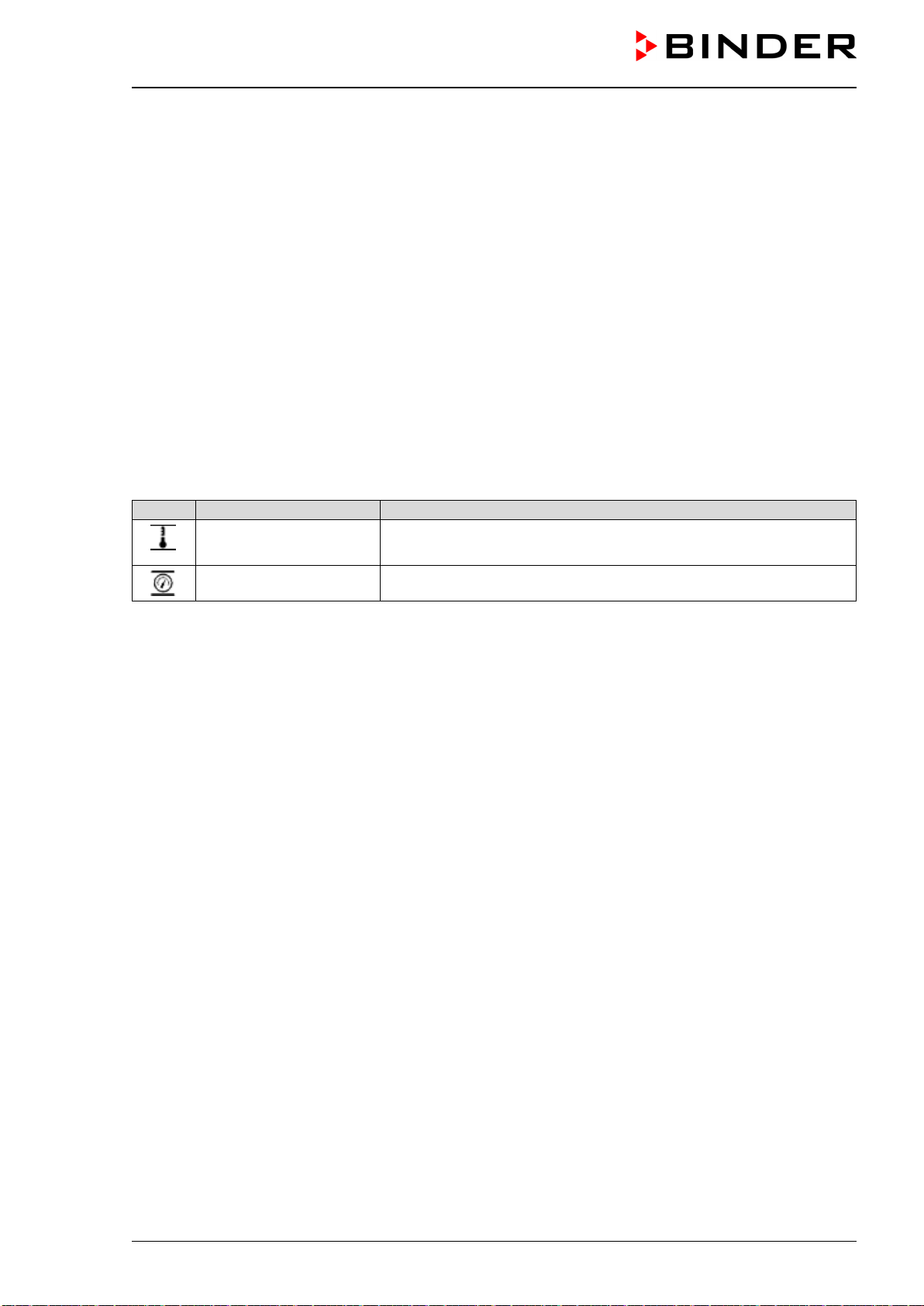
VDL (E3.1) 10/2020 Page 123/196
• Select the field “Temp. alarm delay” and enter the time in minutes, after which the temperature range
alarm shall be triggered. Setting range: 1 min to 120 min. Confirm entry with Confirm icon.
• Select the field “Temperature range” and enter the desired value for the temperature range. Setting
range: 1,0 °C to 10,0 °C. Confirm entry with Confirm icon.
• Select the field “Press. alarm delay” and enter the time in minutes, after which the pressure range alarm
shall be triggered. Setting range: 1 min to 120 min. Confirm entry with Confirm icon.
• Select the field “Pressure range” and enter the desired value for the pressure range. Setting range: 10
mbar to 200 mbar. Confirm entry with Confirm icon.
For testing the safety temperature limiter (TB) see chap. 16.5.
After completing the settings, press the Confirm icon to take over the entries and exit the menu, or press
the Close icon to exit the menu without taking over the entries.
15.1.1 Alarm condition
If there are actual values outside the tolerance range the following information icons for the corresponding
parameter are displayed:
Icon
Signification
Information
“Temperature range”
The current actual temperature value is outside the tolerance
range
“Pressure range” The current actual pressure value is outside the tolerance range
If the condition persists, an alarm is triggered after the configured interval (“range alarm delay”). It is visually
indicated in Normal display. If the alarm buzzer is activated (chap. 16.4) there is an audible alert. The alarm
is shown in the list of active alarms (chap. 16.3).
16. Notification and alarm functions
16.1 Information messages
Information messages are indicated by information icons displayed in the screen header in Normal dis-
play.
An information icon serves as an indication of a certain condition.
If this condition persists, in some cases an alarm will be triggered after a fix or configurable interval. As long
as the condition persists, the information icon therefore continues to be displayed also in state of alarm. If
during alarm the conditions ends, e.g., if during a tolerance range alarm the actual value returns to within
the tolerance range, the information icon disappears, whereas the alarm will continue until manual acknowl-
edgement.
Press the flash icon next to the information icon to access the corresponding text information.
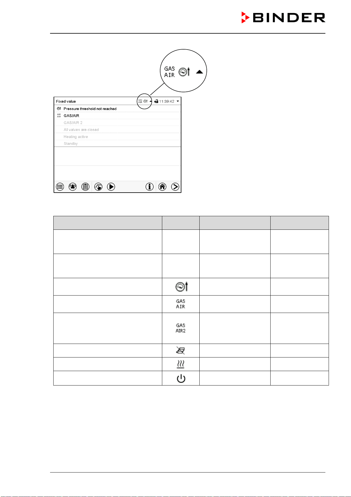
VDL (E3.1) 10/2020 Page 124/196
Normal display showing the text infor-
mation.
The currently valid information texts are
highlighted in black (example: “Pressure
threshold not reached” and “GAS/AIR”)
Information messages overview:
Condition
Information
icon
Text information
Start after
condition occurred
Deactivated temperature control
Temperature setpoint
value display shows
“ – – – – ”
immediately
Deactivated pressure control
Pressure setpoint value
display shows
“ – – – – ”
immediately
Pressure threshold of 100 mbar not
reached
“Pressure threshold not
reached”
immediately
Ventilation via regular connection
“GAS/AIR” (4)
“GAS/AIR” immediately
Ventilation via optional connection
“GAS/AIR 2” (5).
Regular connection “GAS/AIR” (4) de-
activated.
“GAS/AIR 2” immediately
All valves are closed
“All valves are closed” immediately
Chamber is heating up
“Heating active” immediately
Standby mode activated
“Standby” immediately
Information messages are not shown in the event list.
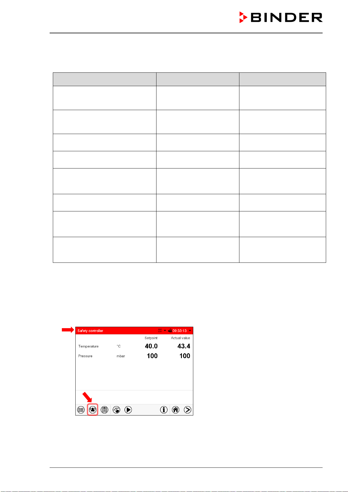
VDL (E3.1) 10/2020 Page 125/196
16.2 Alarm messages
Alarm messages overview:
Condition Alarm message
Start after
condition occurred
The current actual temperature value
is outside the tolerance range (chap.
15)
“Temperature range”
after configurable time
(chap. 15.1)
Factory setting: 10 minutes
The current actual pressure value is
outside the tolerance range (chap. 15
)
“Pressure range”
after configurable time
(chap. 15.1)
Factory setting: 10 minutes
Safety temperature limiter (TL) has
turned off the heater
“Overtemperature” immediately
Exceeded setpoint of the safety con-
troller class 2
“Safety controller” immediately
Inner chamber temperature sensor
defective. Heater turns off.
Actual temperature value dis-
play shows e.g. “- - - - “ or
“<-<-< “ or “>->->”
immediately
Heater temperature sensor defective.
Heater turns off.
“Heater temp.sensor” immediately
Pressure sensor defective
Actual pressure value display
shows e.g. “- - - - “ or
“<-<-< “ or “>->->”
immediately
Failure of temperature sensor for ob-
ject temperature (option)
Object pressure value dis-
play shows e.g. “- - - - “ or
“<-<-< “ or “>->->”
immediately
Alarm messages are displayed in the list of active alarms until acknowledging them. They are also shown
in the event list.
State of alarm
1. Visual indications in Normal display: alarm message, screen header flashing in red color
2. Audible alert, if the buzzer is enabled (chap. 16.4).
Normal display in state of alarm (example).
(a) Screen header
flashing in red color and
showing the alarm message
(b) Alarm icon on the bottom of the screen:
change to the list of active alarms and
alarm acknowledgement
(a)
(b)
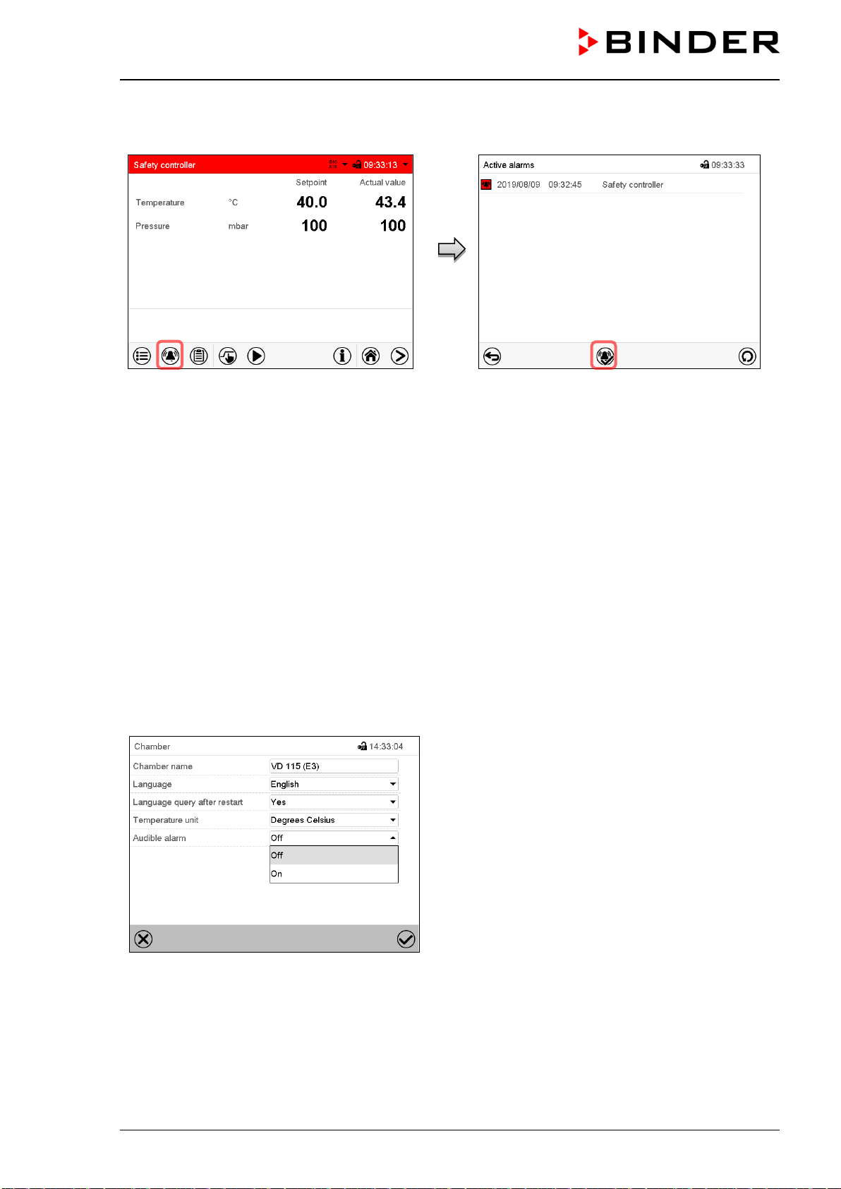
VDL (E3.1) 10/2020 Page 126/196
16.3 Resetting an alarm
Normal display in state of alarm (example).
Press the Alarm icon.
List of active alarms.
Press the Reset alarm icon.
Pressing the Reset alarm icon mutes the buzzer for all active alarms. The icon then disappears.
• Acknowledging while the alarm condition persists: Only the buzzer turns off. The visual alarm indication
remains on the controller display. The alarm remains in the list of active alarms.
When the alarm condition has ended, the visual alarm indication is automatically cleared. The alarm is
then no longer in the list of active alarms.
• Acknowledging after the alarm condition has ended: The buzzer and the visual alarm indication are reset
together. The alarm is then no longer in the list of active alarms.
16.4 Activating / deactivating the audible alarm (buzzer)
Path: Main menu > Settings > Chamber
“Chamber” submenu (example).
In the field “Audible alarm” select the desired setting
“off“ or “on” and press the Confirm icon.
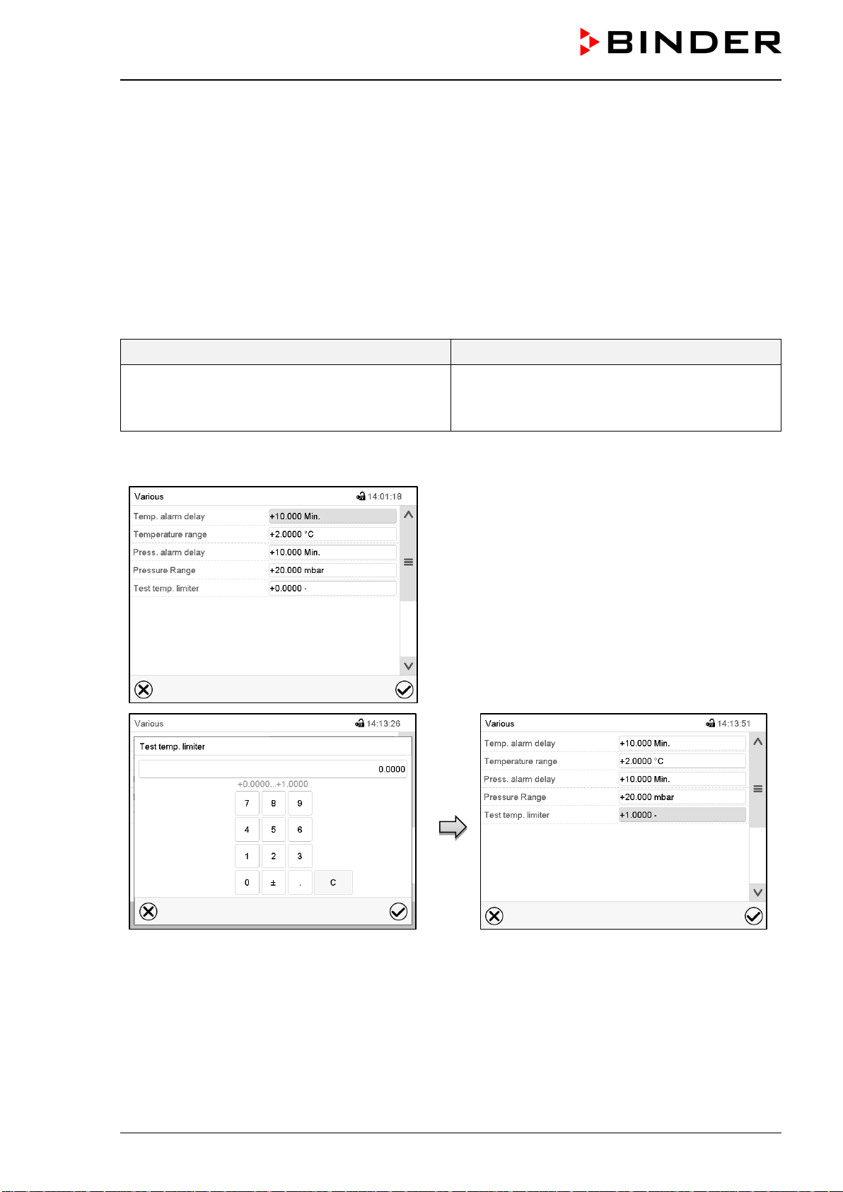
VDL (E3.1) 10/2020 Page 127/196
16.5 Test alarm of the safety temperature limiter (TL)
The safety temperature limiter (TL) provides temperature monitoring with a fixed switching threshold. It is
an essential element of the manufacturer's safety plan to prevent ignition and explosions (chap. 3.1). There-
fore, an annual function check by the operator is recommended. To do this, you can use the controller test
routine described following. The test is performed on an empty chamber (without vacuum expansion racks
and rack holders).
If the ambient temperature is below 28 °C, the chamber must be heated up to 28 °C to 38 °C before starting
the test. To activate the heating, the chamber must first be evacuated below 100 mbar. This negative pres-
sure is maintained during the test.
For chambers equipped with a single safety temperature limiter (TL), this is tested with the setting “1”. For
chambers with 2 TB, the test is run twice, first with the setting “1” and then again with the setting “2”.
Chambers with one TL Chambers with two TL
VDL 23
VDL 23-UL
VDL 115
VDL 56
VDL 56-UL
VDL 115-UL
Path: Main menu > Settings > Various
Submenu “Various”.
“Test temp. limiter” setting menu.
To activate the test alarm for the first TL, enter
“1” and press the Confirm icon.
Submenu “Various” with activated test alarm
“1”.
Press the Confirm icon and go back to Normal
display.
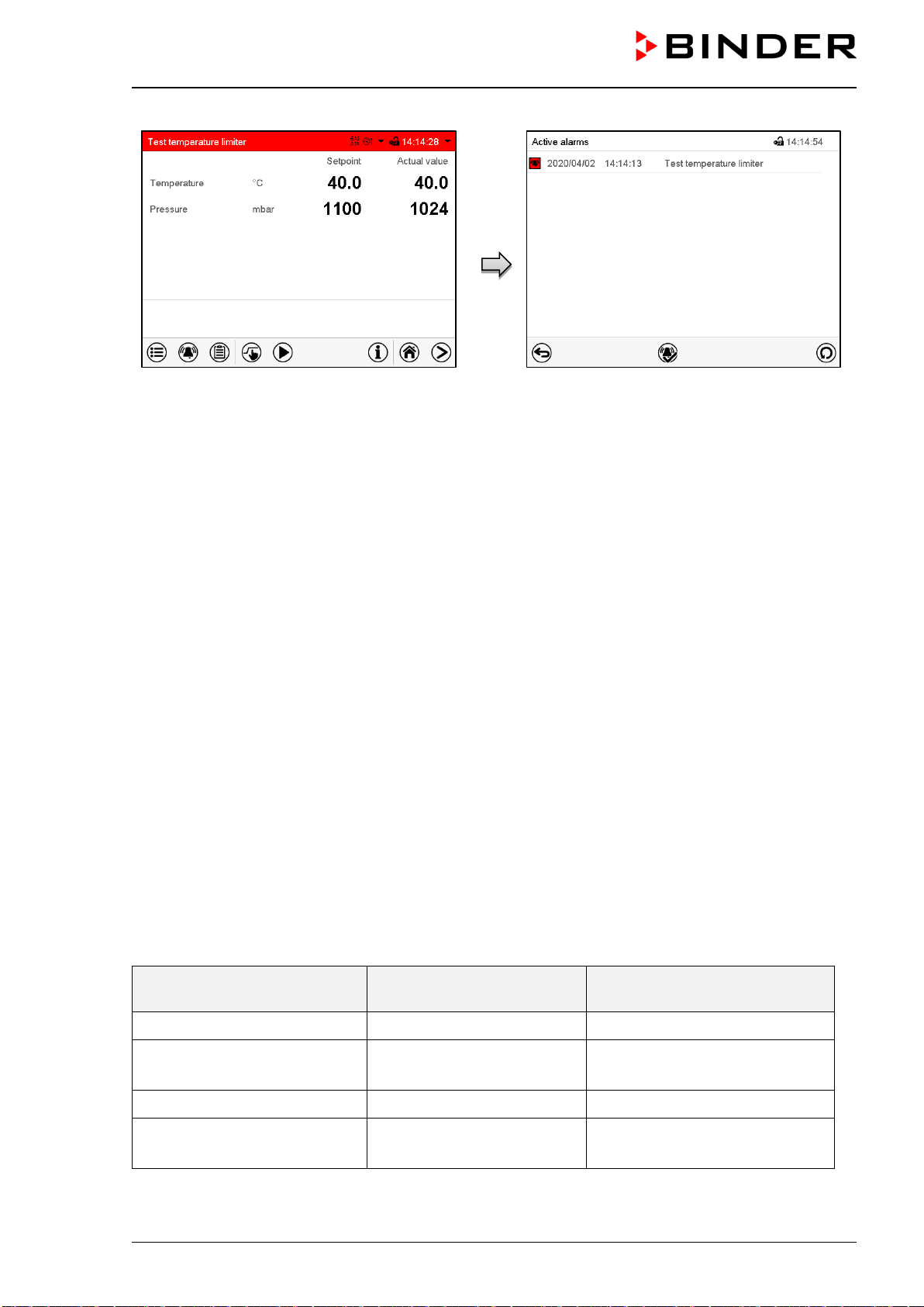
VDL (E3.1) 10/2020 Page 128/196
Normal display in state of alarm (sample val-
ues)
The alarm message “Test temperature limiter”
Screen header flashes in red color. if the buzzer
is enabled there is an audible alert. Press the
Alarm icon.
List of active alarms.
Press the Reset alarm icon.
The chamber only starts heating if the current actual value of the unit has reached at least once a value
below 40 °C. The chamber continues heating until one of the following alarm messages appears:
• If the test is passed, the alarm message “Temperature limiter 1 triggered” will be displayed.
• If the test fails, the alarm message “Temperature limiter 1 error” is displayed.
To deactivate the test alarm, go back to the “Test temp. limiter” setting menu and set the value to “0” (test
alarm deactivated).
Then pull out the power plug und let the chamber cool down for 30 minutes. Plug in the power plug again
to return to normal chamber operation.
For the chambers with a single safety temperature limiter (TL), the test is completed here.
For the chambers with two safety temperature limiters (TL), carry out another test for the second TL. For
this purpose, the inner temperature must have cooled down to a value between 28 °C and 38 °C after the
first test.
Enter “2” in the “Test temp. limiter” setting menu to activate the test alarm for the second TL and press the
Confirm icon. Then proceed as described above.
The following table gives an overview of the maximum trigger times of the different chamber models.
If the safety temperature limiter is triggered before the end of this maximum trigger time, the test is consid-
ered passed. This corresponds to the alarm message “Temperature limiter 1 triggered” or “Temperature
limiter 2 triggered”.
After the maximum trigger time has expired, the test is considered as failed. This corresponds to the alarm
message “Temperature limiter 1 error” or “Temperature limiter 2 error”.
Chamber Test Maximum trigger time
in minutes
VDL 23, VDL 23-UL 1 16
VDL 56, VDL 56-UL 1
2
20
55
VDL 115 1 17
VDL 115-UL 1
2
17
22
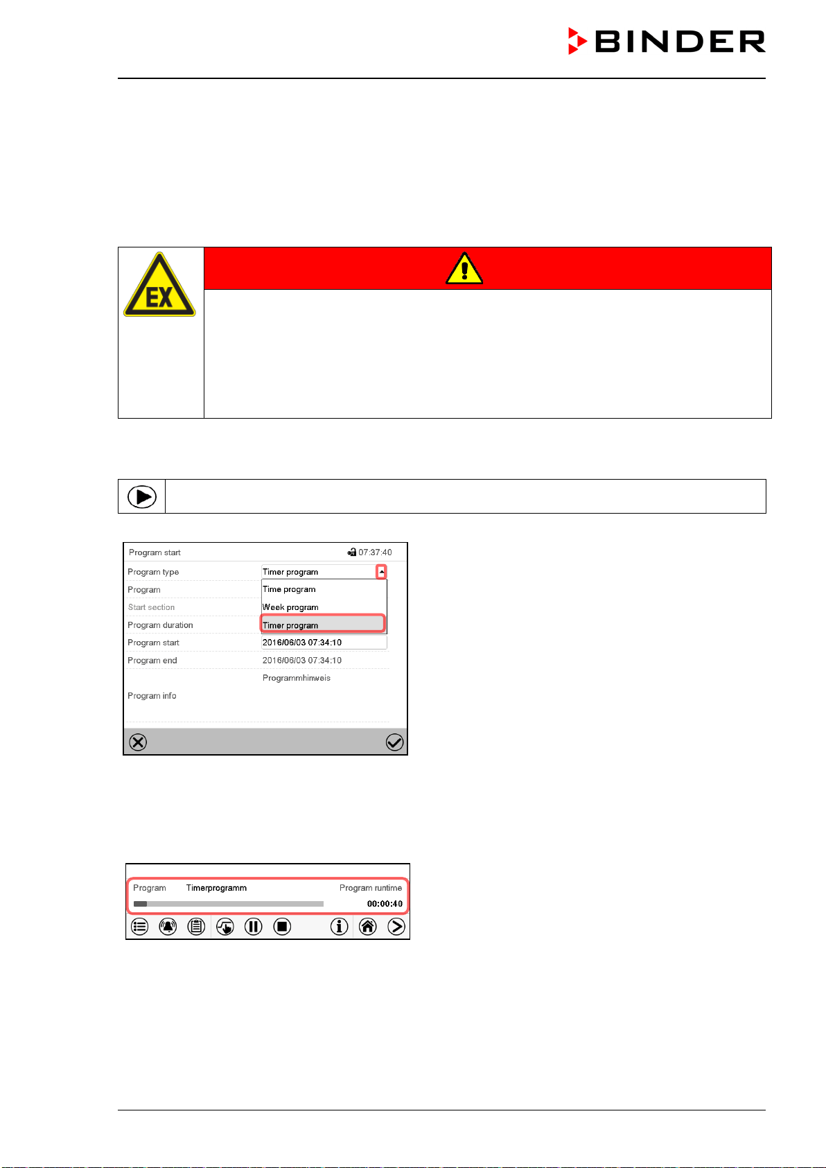
VDL (E3.1) 10/2020 Page 129/196
17. Timer program (stopwatch function)
During an entered duration the controller constantly equilibrates to the setpoints entered in Fixed value
operation mode (temperature, pressure, configuration of the special controller functions). This duration can
be entered as a “Timer program”. During the program runtime, any setpoint changes do not become effec-
tive; the controller equilibrates to the values which were active during program start.
Solvents and forming vapors can ignite if the drying temperature is too high
DANGER
Fire and explosion hazard when exceeding the auto-ignition temperature of the sol-
vent due to excess drying temperature.
Serious injury or death from burns and / or explosion pressure.
Make sure that only solvents with an auto-ignition temperature that is higher than
200 °C / 392 °F may be entered into the chamber. Check the auto-ignition temperature
with the safety specifications of the solvent. In the case of solvent mixtures, use the
auto-ignition temperature of the material with the lowest auto-ignition temperature.
17.1 Starting a timer program
In Normal display press the Program start icon to access the “Program start” menu.
“Program start” menu
• In the field “Program type” select “Timer program”.
• Select the field “Program duration” and enter the desired program duration. Press the Confirm icon.
• Select the field “Program start” and enter the desired start time of the program in the “Program start”
entry menu. Press the Confirm icon. The program delay time until program start begins.
Normal display.
Information on the bottom of the screen indicates the
currently running program and the time already
passed. The grey bar shows how much time of the
whole time is elapsed.
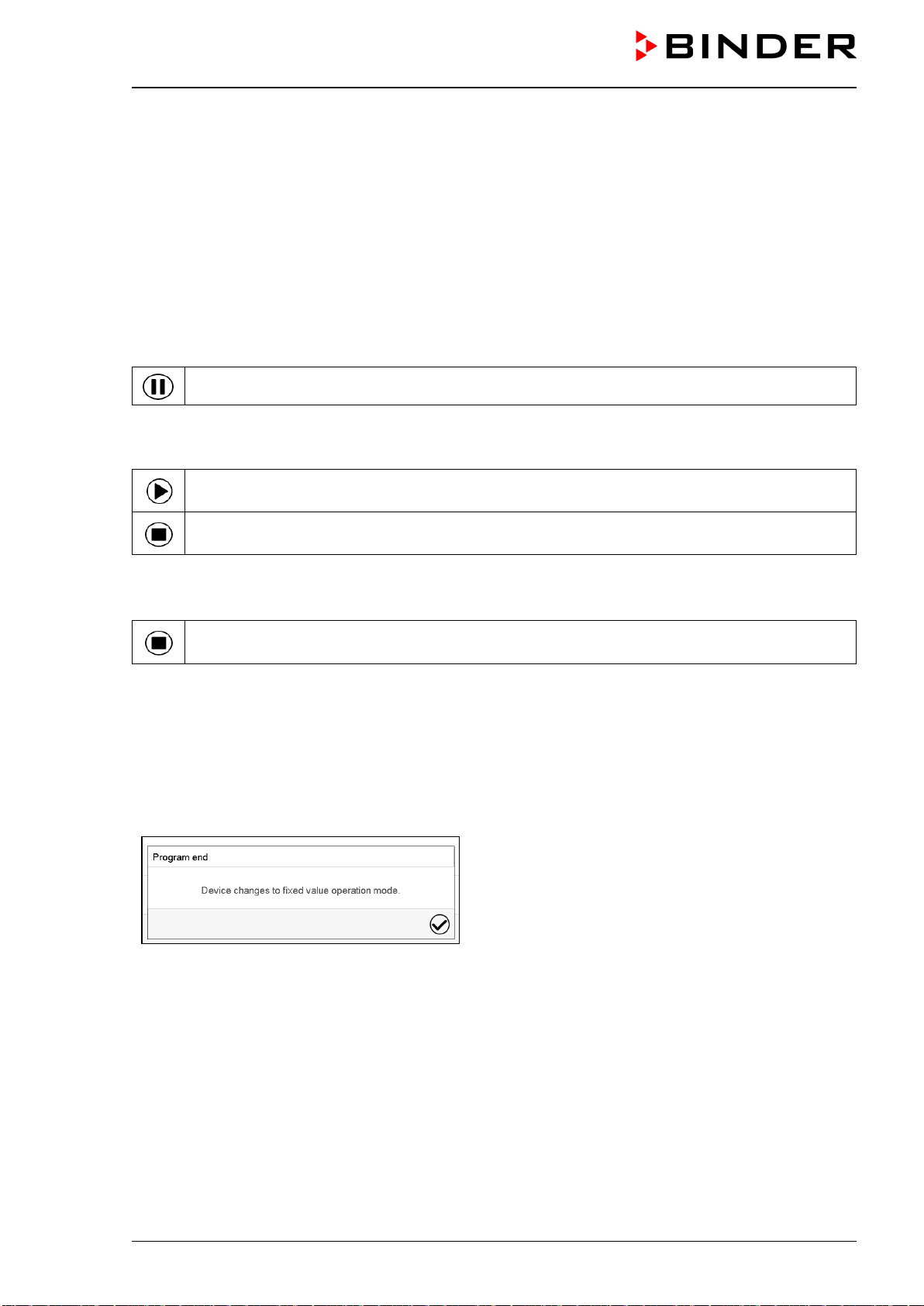
VDL (E3.1) 10/2020 Page 130/196
17.1.1 Performance during program delay time
During the configured program delay time until program start, the controller equilibrates to the current set-
points of Fixed value operation mode. Modifications of these setpoints are possible but become effective
only after the timer program is finished. When the configured moment for program start is reached, the
program delay time ends and the program starts running. The controller equilibrates to the values which
had been active during program start.
17.2 Stopping a running timer program
17.2.1 Pausing a running timer program
Press the Program pause icon to interrupt the program.
The program is paused. The program runtime stops running down, the time display flashes.
There are the following options:
Press the Program start icon to continue the program
Press the Cancelling icon to cancel the program
17.2.2 Cancelling a running timer program
Press the Program cancelling icon to cancel the program.
A confirmation prompt is displayed. Press the Confirm icon to confirm that the program shall really be
cancelled.
After confirming the message the controller changes to Fixed value operation mode. Temperature and
humidity will then equilibrate to the setpoints of Fixed value operation mode.
17.3 Performance after the end of the program
After the end of the program the message “Device
changes to fixed value operation mode” appears on
the screen.
Press the Confirm icon.
After confirming the message the controller changes to Fixed value operation mode. Temperature and
humidity will then equilibrate to the setpoints of Fixed value operation mode.
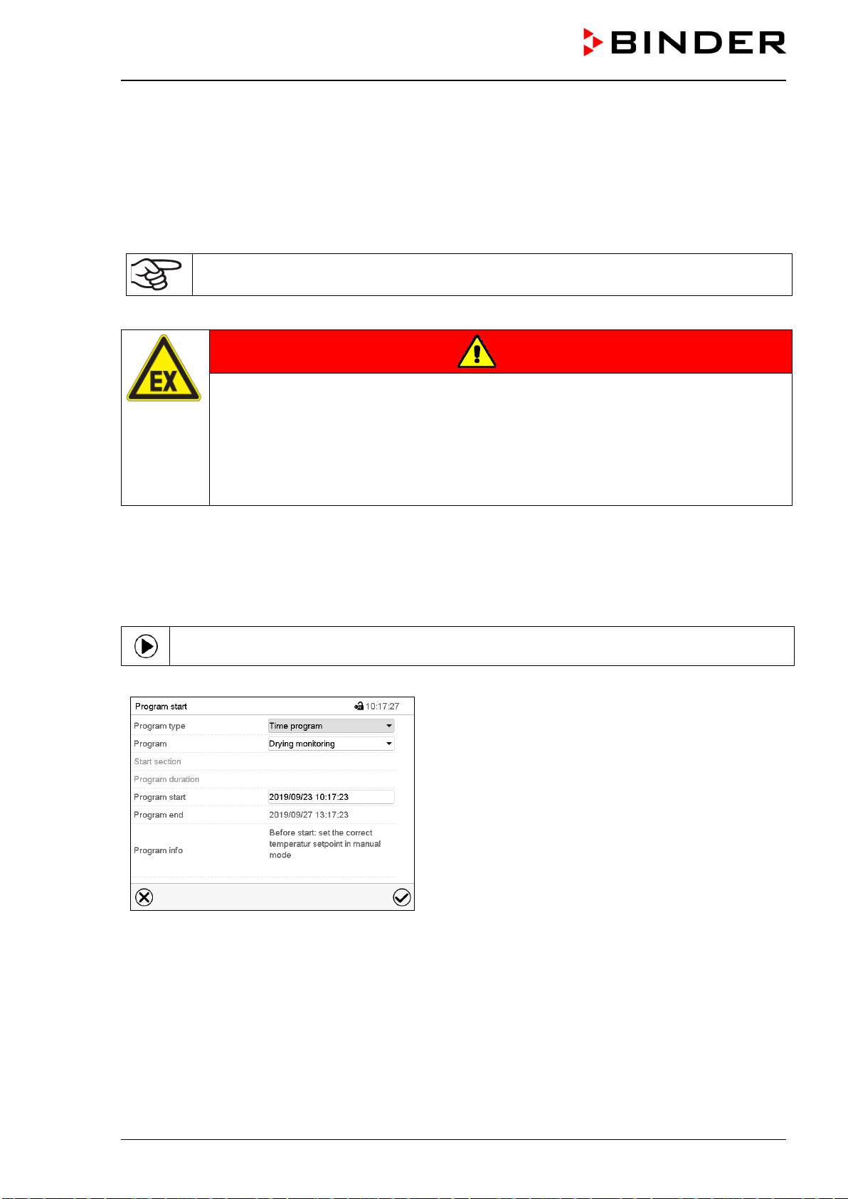
VDL (E3.1) 10/2020 Page 131/196
18. Time programs
The MB2 program controller permits programming time programs with real-time reference. It offers 25 pro-
gram memory positions with up to 100 program sections each.
For each program section you can enter a temperature set-point, a pressure set-point, section duration,
type of temperature and pressure transition (ramp or step), the switching states of the special controller
functions and the tolerance ranges.
Before starting the program, check the set-points entered in fixed value mode. After the end
of the program, the set-points will equilibrate to these values
Solvents and forming vapors can ignite if the drying temperature is too high.
DANGER
Fire and explosion hazard when exceeding the auto-ignition temperature of the sol-
vent due to excess drying temperature.
Serious injury or death from burns and / or explosion pressure.
Make sure that only solvents with an auto-ignition temperature that is higher than
200 °C / 392 °F may be entered into the chamber. Check the auto-ignition temperature
with the safety specifications of the solvent. In the case of solvent mixtures, use the
auto-ignition temperature of the material with the lowest auto-ignition temperature.
Programming remains saved in case of a power failure or after turning off the unit.
Path: Main menu > Programs> Time program
18.1 Starting an existing time program
In Normal display press the Program start icon to access the “Program start” menu.
“Program start” menu
• In the field “Program type” select the setting “Time program”.
• In the field “Program” select the desired program.
• Select the field “Program start” and enter the desired program start time in the “Program start” entry
menu. Press the Confirm icon. The program delay time until program start begins.
The program end is adapted automatically depending on the entered program duration.
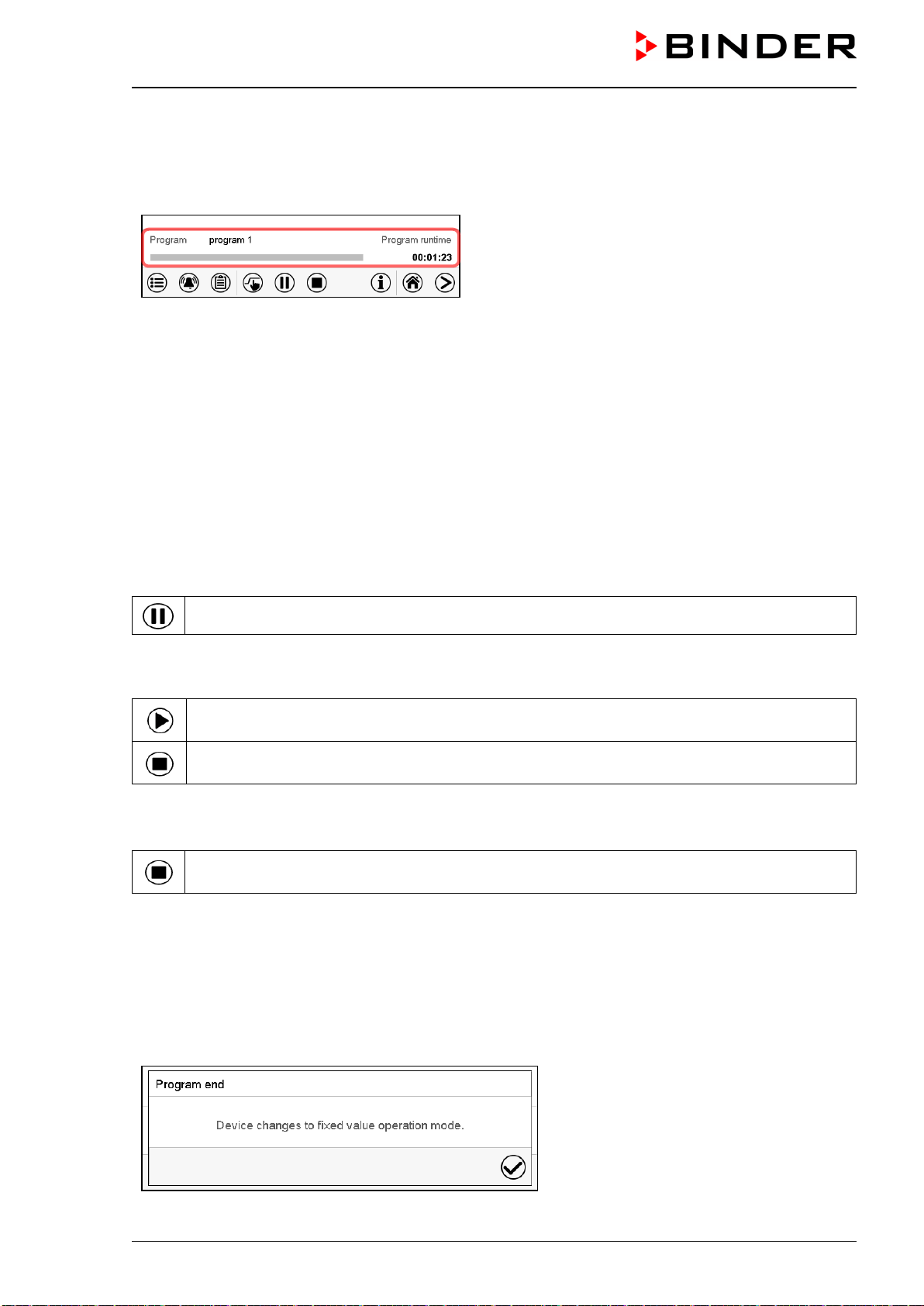
VDL (E3.1) 10/2020 Page 132/196
After completing the settings, press the Confirm icon to take over the entries and exit the menu. The pro-
gram starts running.
If instead you press the Close icon to exit the menu without taking over the entries, the program will not
start.
Normal display. Information on the bottom of the
screen indicates the currently running program and the
time already passed. The grey bar shows how much
time of the whole time is elapsed. If program duration
has been set to infinite, the grey bar is not displayed.
Heating takes place only when a vacuum according to the pressure threshold of 100 mbar is reached. Only
then start the program or set a tolerance range for the first program section.
18.1.1 Performance during program delay time
During the configured program delay time until program start, the controller equilibrates to the current set-
points of Fixed value operation mode. Modifications of these setpoints are effective. When the configured
moment for program start is reached, the program delay time ends and the program starts running.
18.2 Stopping a running time program
18.2.1 Pausing a running time program
Press the Program pause icon to interrupt the program.
The program is paused. The program runtime stops running down, the time display flashes.
There are the following options:
Press the Program start icon to continue the program
Press the Cancelling icon to cancel the program
18.2.2 Cancelling a running time program
Press the Program cancelling icon to cancel the program.
A confirmation prompt is displayed. Press the Confirm icon to confirm that the program shall really be
cancelled.
After confirming the message, the controller changes to Fixed value operation mode. Temperature and
humidity will then equilibrate to the setpoints of Fixed value operation mode.
18.3 Performance after the end of the program
After the end of the program the message
“Device changes to fixed value operation
mode” appears on the screen.
Press the Confirm icon.
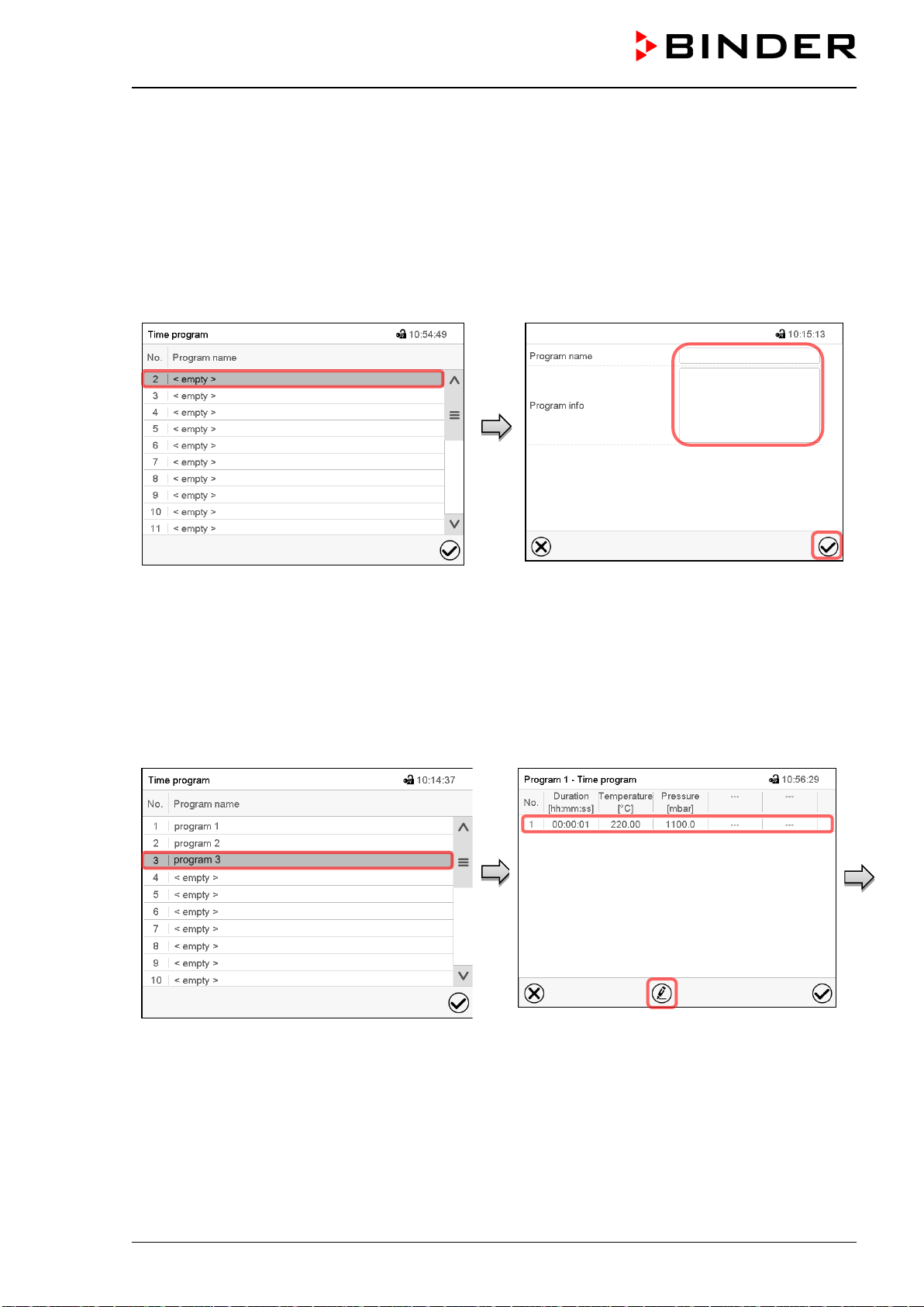
VDL (E3.1) 10/2020 Page 133/196
As long as the message has not been confirmed, the setpoint of the last program section remains effective.
Program the last section as desired. If e.g. temperature and pressure control shall turn off, activate the
corresponding controller functions (chap. 11.4, 11.5).
After confirming the message, the controller changes to Fixed value operation mode. Temperature and
humidity will then equilibrate to the setpoints of Fixed value operation mode.
18.4 Creating a new time program
Path: Main menu > Programs > Time program
“Time program” menu:
overview of the existing programs.
Select an empty program place.
Enter the program name and, if desired, addi-
tional program information in the corresponding
fields.
Press the Confirm icon.
The program view opens (chap. 18.5).
18.5 Program editor: program management
Path: Main menu > Programs > Time program
“Time program” menu:
overview of the existing programs.
Select an existing program (example: program
3) or create a new program (chap. 18.4).
The program view opens.
Program view (example: program 3).
If a new program has been created, there is
just one program section.
There are the following options:
Select a program section to open the sec-
tion editor (chap.
18.6)
Press the Edit icon to open the program
editor
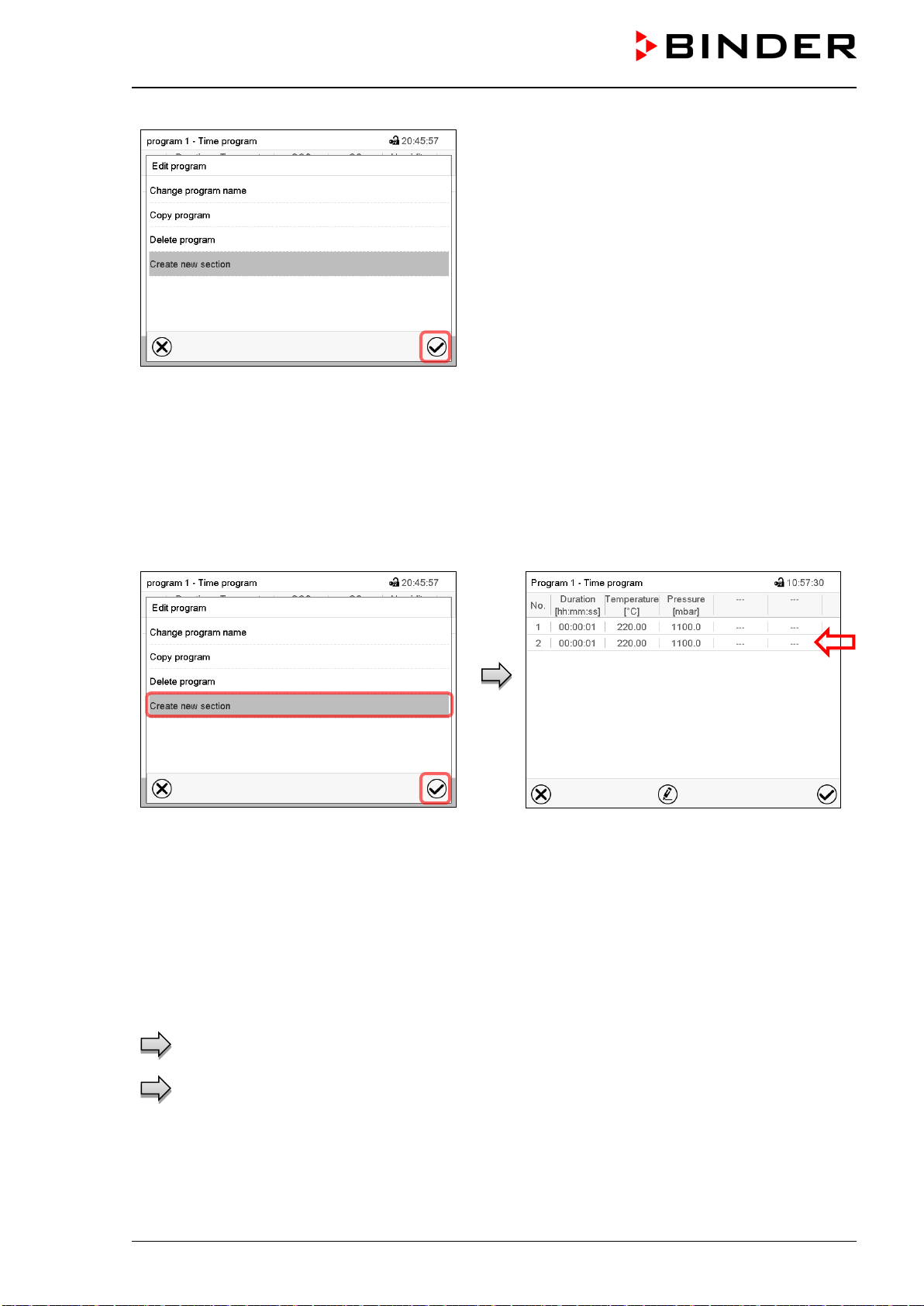
VDL (E3.1) 10/2020 Page 134/196
Program editor: “Edit program” menu
Select the desired function and press the Confirm
icon.
The program editor offers following options:
• Change the program name
• Copy program
• Replace program: Replacing a new or an existing program with the copied program. This menu point is
visible only after a program has been copied.
• Delete program
• Create new section
.
To add a new section, select “Create new sec-
tion” and press the Confirm icon.
The program view opens.
Program view.
A new section is always added at the very bot-
tom (example: section 2).
18.5.1 Deleting a time program
Path: Main menu > Programs > Time program
In the “Time program” menu select the program to be deleted. The program view opens.
In the program view press the Edit icon to open the program editor
In the program editor select “Delete program” and press the Confirm icon.
The program is deleted. The controller returns to the program view.
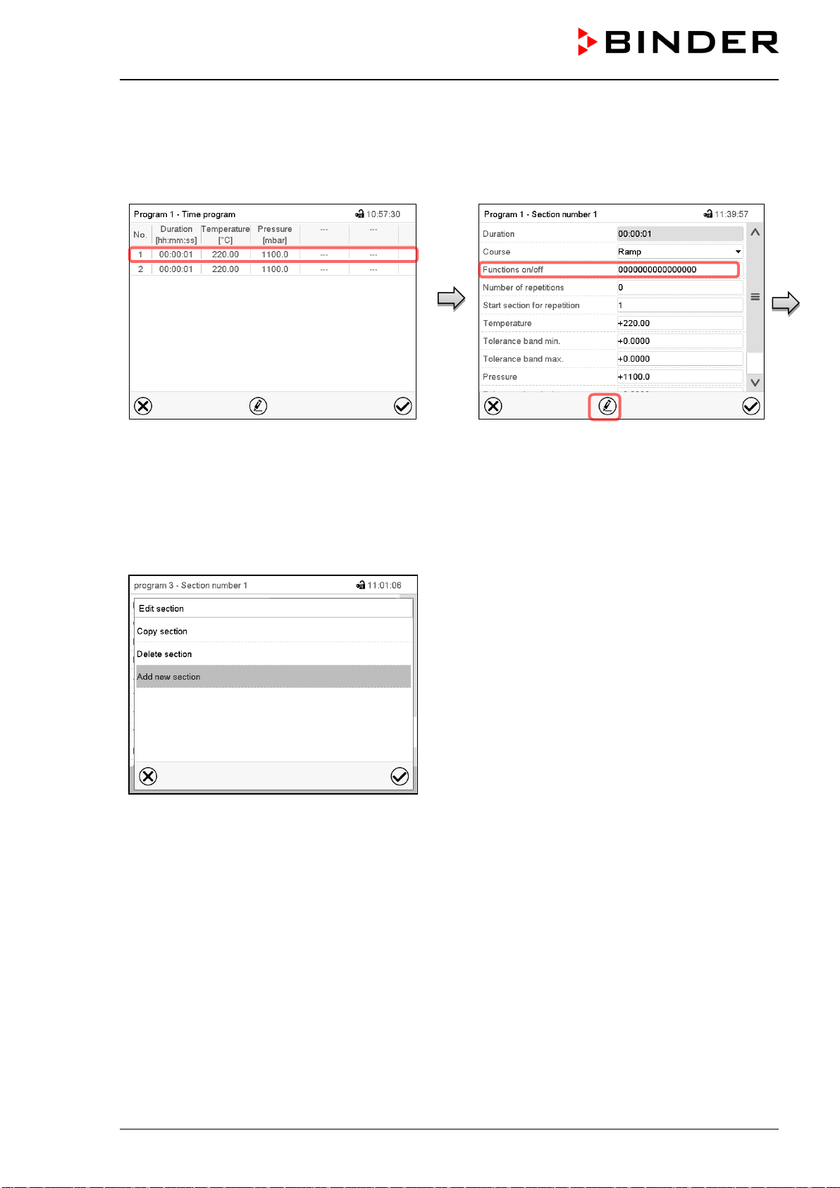
VDL (E3.1) 10/2020 Page 135/196
18.6 Section editor: section management
Path: Main menu > Programs > Time program
Select the desired program.
Program view.
Select the desired program section
(example: section 1)
Section view (example: section 1).
There are the following options:
Select a parameter to enter or modify
the according value (chap.
18.7)
Press the Edit icon to open the program
editor
Section editor: “Edit section” menu
Select the desired function and press the Confirm icon.
The section editor offers following options:
• Copy section
• Replace section: Replacing an existing section with the copied section. This menu point is visible only
after a section has been copied.
• Insert section: Adding the copied section. This menu point is visible only after a section has been copied.
• Delete section
• Add new section
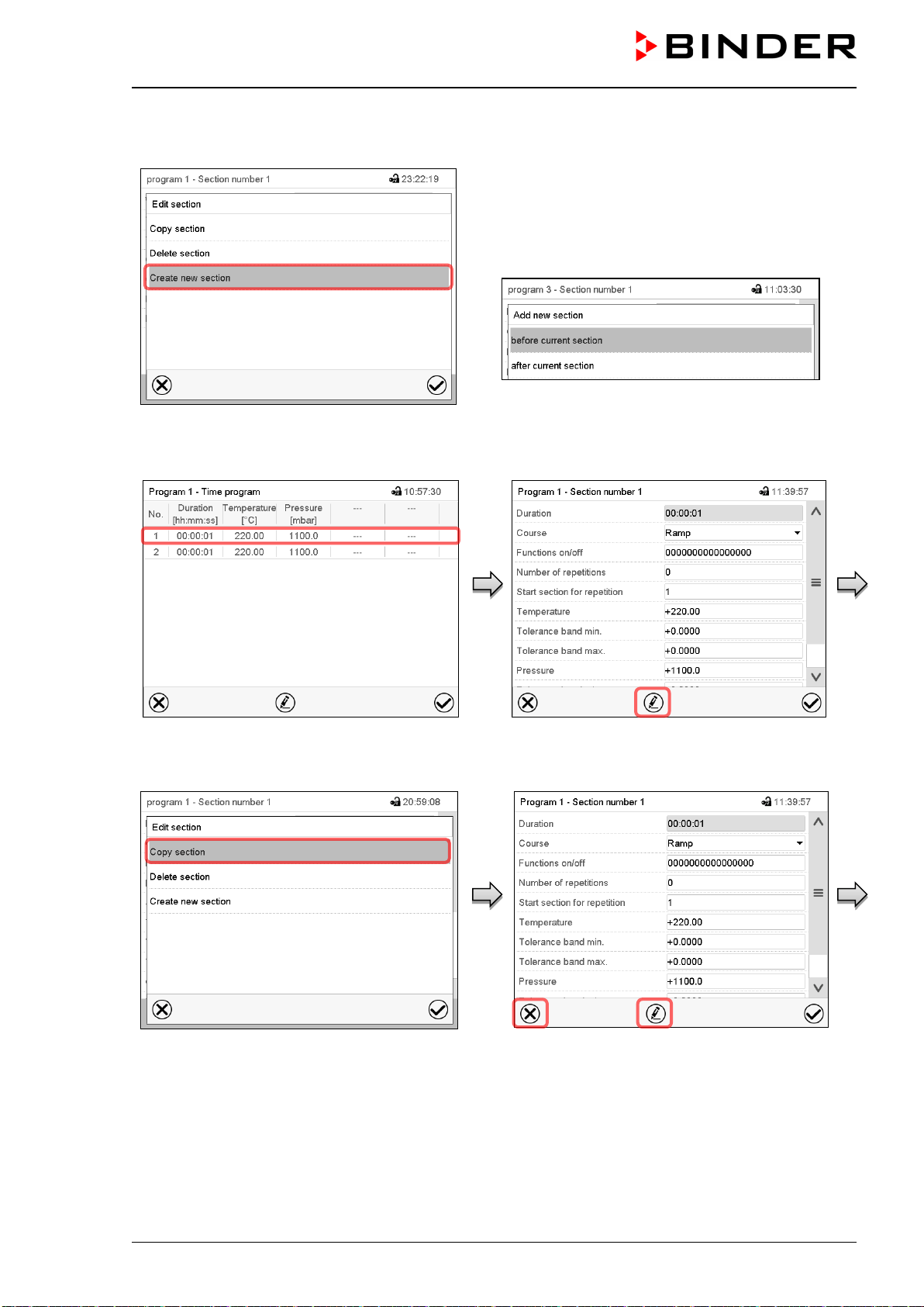
VDL (E3.1) 10/2020 Page 136/196
18.6.1 Add a new program section
Section editor: “Edit section” menu.
Select “Create new section” and press the Confirm
icon.
Then select whether to insert the new section be-
fore or after the current section.
Press the Confirm icon. The new section opens.
18.6.2 Copy and insert or replace a program section
Program view.
Select the program section to be copied
(example: section 1)
Section view (example: section 1).
Press the Edit icon to open the section editor.
Section editor: “Edit section” menu
Select “Copy section” and press the Confirm
icon.
The current section (example: section 1) is
copied. The controller returns to the section
view.
Section view (example: section 1).
Press the Close icon to change to the pro-
gram view, if you want to select another sec-
tion to be replaced or before or after which
the copied section shall be inserted…
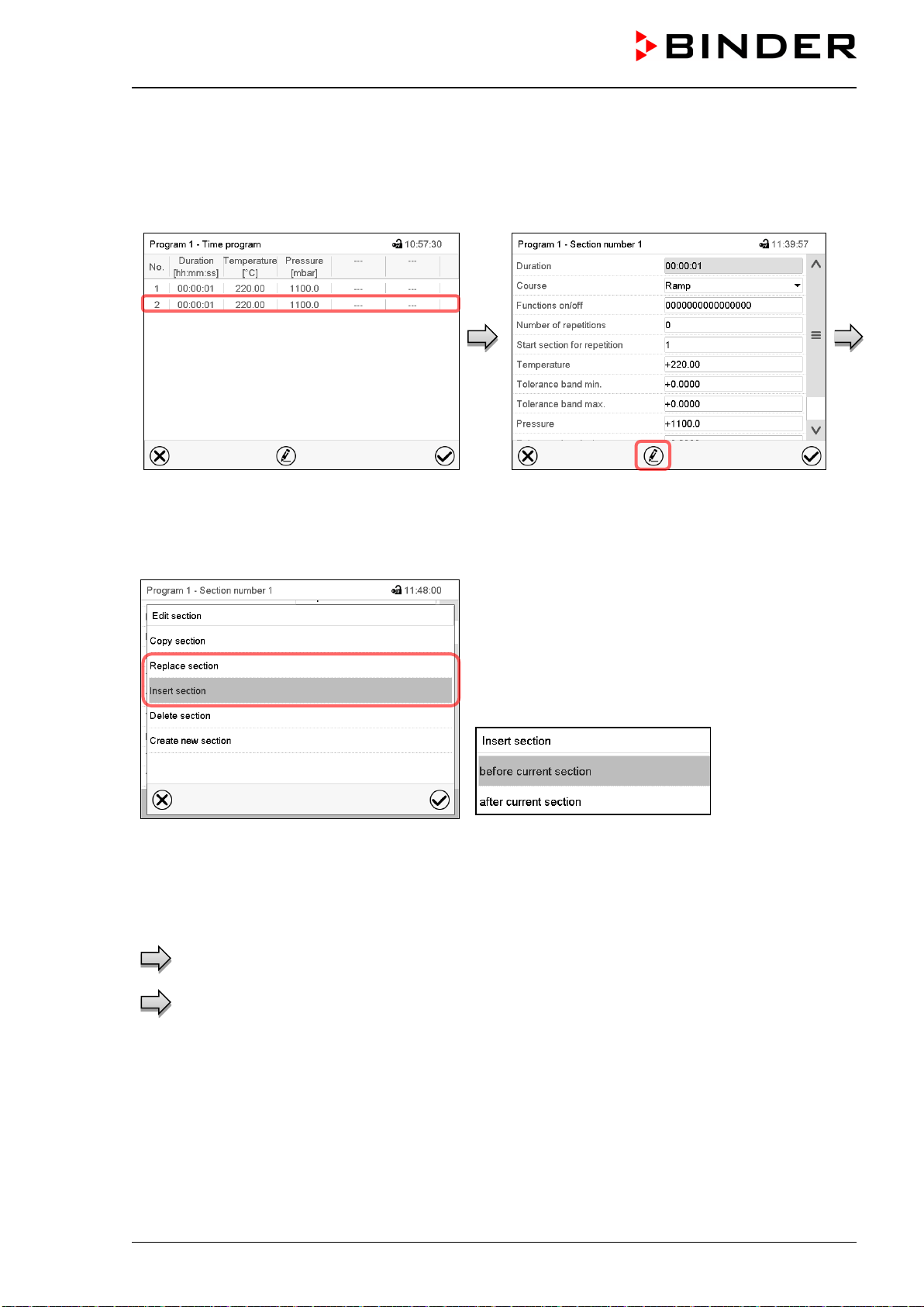
VDL (E3.1) 10/2020 Page 137/196
or
Press the Edit icon to open the section editor
if you want the current section to be replaced
or the copied section to be inserted before or
after it
Program view.
Select the section to be replaced or before or
after which the copied section shall be in-
serted (example: section 2) and press the
Confirm icon.
Section view (example: section 1).
Press the Edit icon to open the section editor
Section editor: “Edit section” menu
Select “Replace section” to replace the selected section
with the copied section
or
Select “Insert section” to additionally add the copied
section.
In this case select whether to insert it before or after the
selected section.
Press the Confirm icon
18.6.3 Deleting a program section
In the program view select the program section to be deleted. The section view opens.
In the section view press the Edit icon to open the section editor
In the section editor select “Delete section” and press the Confirm icon.
The section is deleted. The controller returns to the section view.
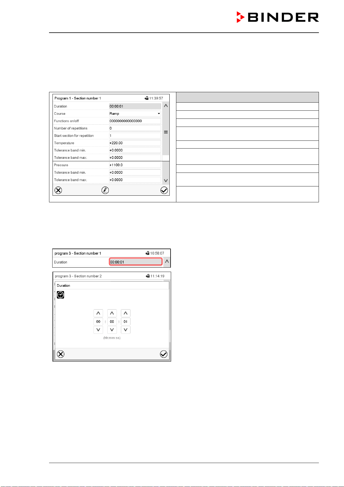
VDL (E3.1) 10/2020 Page 138/196
18.7 Value entry for a program section
Path: Main menu > Programs > Time program
Select the desired program and section.
The section view gives access to all parameters of a program section. You can enter or modify the values.
Program name and section number
Section duration
Type of setpoint transition: ramp or step
Special controller function
Repeating one or several sections within a program
Temperature setpoint
Temperature tolerance range: minimum and maxi-
mum
Pressure setpoint
Pressure tolerance range: minimum and maximum
The setting and control ranges for the individual parameters are the same as for “Fixed value” operating
mode.
18.7.1 Section duration
Section view (partial view).
Select the field “Duration” indicating the time.
“Duration” entry menu.
Enter the desired section duration with the arrow keys
and press the Confirm icon.
Setting range: 0 up to 99 hours 59 min 59 sec.
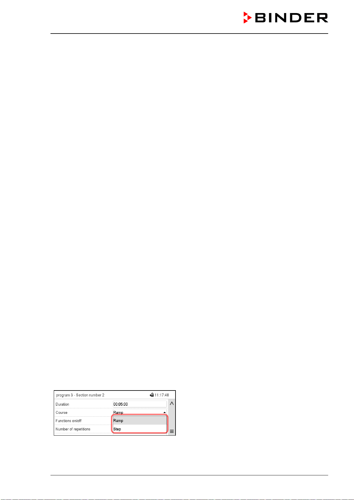
VDL (E3.1) 10/2020 Page 139/196
18.7.2 Set-point ramp and set-point step
You can define the type of temperature and pressure transitions for each individual program section.
“Ramp” mode: Gradual changes of temperature and pressure
The set-point of a given program section functions as the section’s start temperature. During the section’s
duration, the set-point gradually passes to the set-point of the subsequent program section. The actual
value follows the continually changing set-point.
If the last program section is in “ramp” mode and the setpoint shall change within this section, then you
must program an additional section (with the shortest possible section duration) to provide the target tem-
perature of the last program section. Otherwise, the setpoint would remain constant during the section’s
duration.
Programming in the “ramp” mode allows all kinds of temperature and humidity transitions:
• Gradual changes of temperature and pressure
The setpoint changes its value gradually during the entered section duration. The actual value follows
the continually moving set-point at any time.
• Program sections with constant temperature and pressure
The setpoints (initial values) of two subsequent program sections are identical; so, the temperature and
pressure remain constant during the entire duration of the first program section.
• Sudden changes of temperature and pressure
Steps can be programmed in ramp mode as temperature or humidity changes (ramps) that occur during
a very short interval. If the duration of this transitional program section is very short (minimum entry 1
sec), the temperature or humidity change will proceed rapidly within the minimum amount of time.
“Step” mode: Sudden changes of temperature and pressure
The set-point of any program section functions as the section’s target value. At the start of the program
section, the unit heats up and evacuates / ventilates the chamber with the maximum speed to reach the
entered value; and then it holds it for the remaining section time. Therefore, the set-point temperature
remains constant for the section’s duration. These changes occur rapidly within the minimum amount of
time (minimum entry: 1 second).
Programming in the “step” mode allows only two kinds of temperature and pressure transitions:
• Programming gradual changes of temperature and humidity (ramps) is impossible in the “step” mode
• Program sections with constant temperature and pressure
The setpoints (target values) of two subsequent program sections are identical; so, the temperature and
pressure remain constant during the entire duration of the first program section.
• Sudden changes of temperature and pressure
The entered setpoint of the section is reached as fast as possible and then held constant for the remain-
ing section duration.
Selecting the setting “Ramp” or “Step”
Section view (partial view).
In the field “Course” select the desired setting
“Ramp” or “Step”.
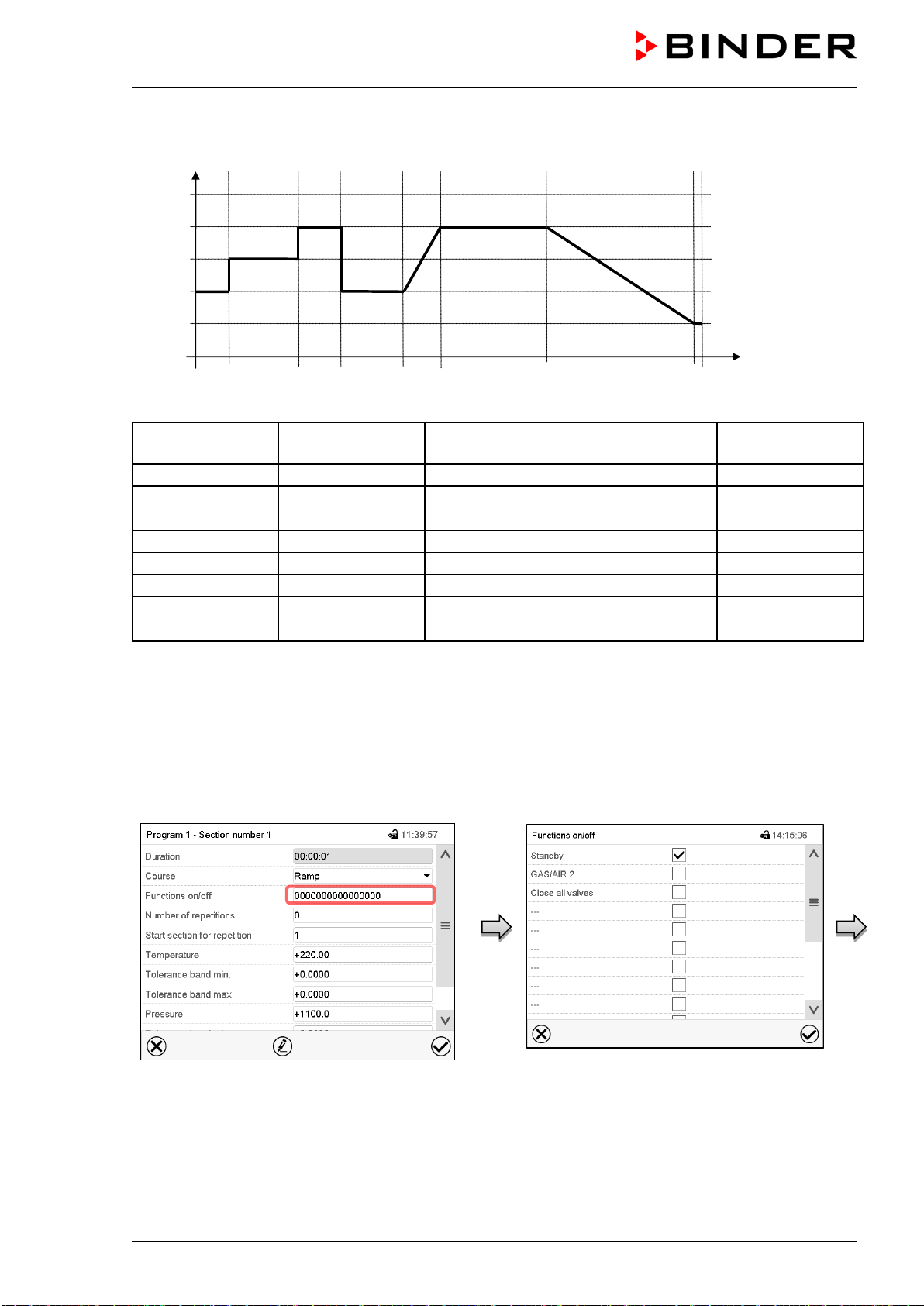
VDL (E3.1) 10/2020 Page 140/196
“Ramp” and “Step” mode example (representation of a temperature course)
W/°C
t/min.
0
20
40
60
80
100
10
30 40 60 70 100
130
1
2
3 4 5 6 7 8
Corresponding program table
Section No.
Duration
[hh:mm:ss]
Temperature
[°C]
Pressure
mbar]
Ramp or Step
1
00:10:00
40.0
xxxx
Step
2
00:20:00
60.0
xxxx
Step
3
00:10:00
80.0
xxxx
Step
4
00:20:00
40.0
xxxx
Step
5
00:10:00
40.0
xxxx
Ramp
6
00:30:00
80.0
xxxx
Ramp
7
00:30:00
80.0
xxxx
Ramp
8
00:00:01
20.0
xxxx
Ramp
18.7.3 Special controller functions
In the “Functions on/off” menu you can define the switching state of three controller functions.
• Function “Standby” (chap. 9.5)
• Function “GAS/AIR 2” (chap. 11.2)
• Function “Close all valves” (chap. 11.3)
Section view.
Select the field “Functions on/off”.
“Functions on/off” entry menu.
Mark / unmark the checkbox of the desired
function to activate / deactivate it and press
the Confirm icon.
The controller returns to the section view.
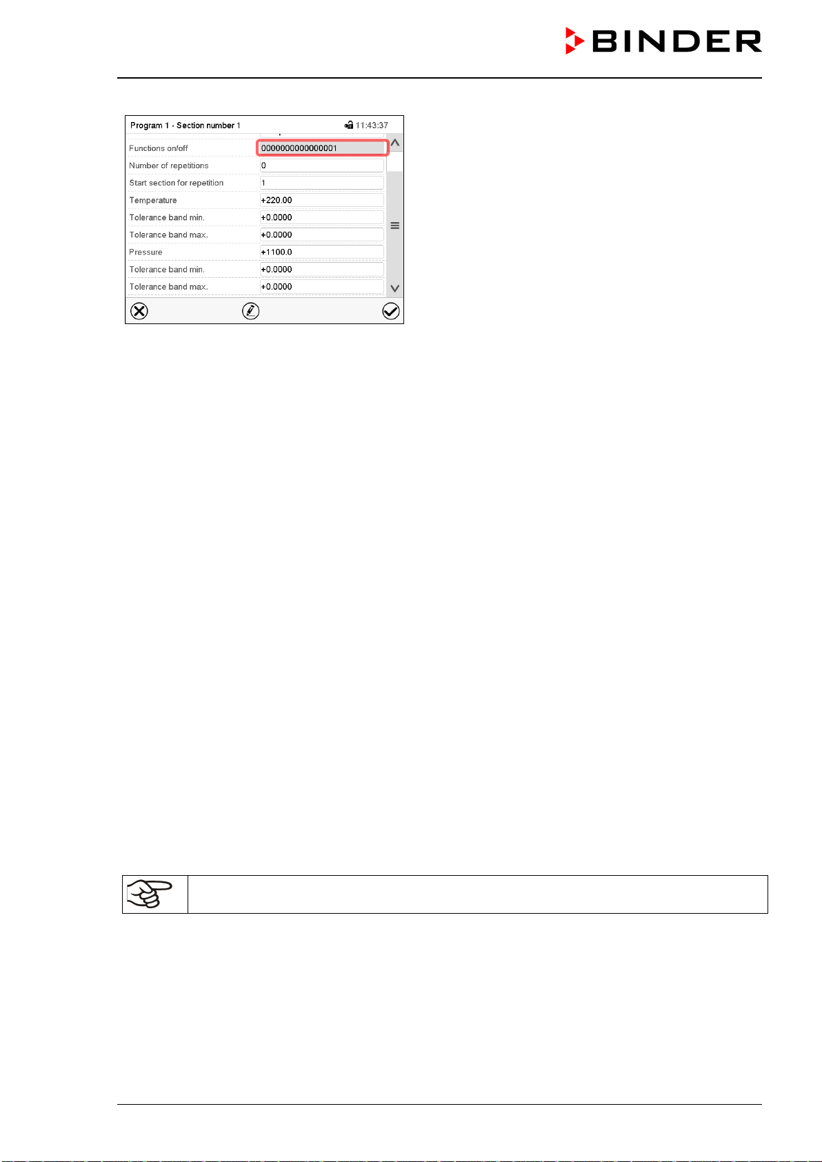
VDL (E3.1) 10/2020 Page 141/196
Section view indicating the controller functions.
The functions are displayed from right to left.
Activated function: switching status “1” (On)
Deactivated function: switching status “0” (Off)
Example:
Activated function “Standby” = 000000000000000
1
Deactivated function “Standby” = 000000000000000
0
18.7.4 Setpoint entry
• Select the field “Temperature” and enter the desired temperature setpoint.
Setting range: 0.0 °C up to 110.0 °C
Confirm entry with Confirm icon. The controller returns to the section view.
• Select the field “Pressure” and enter the desired pressure setpoint.
Setting range: 0 mbar up to 1100 mbar
Confirm entry with Confirm icon. The controller returns to the section view.
18.7.5 Tolerance range
You can specify a temperature and pressure program tolerance range for each program section with differ-
ent values for the tolerance minimum and maximum. When the actual value exceeds the given threshold,
the program is interrupted. This is indicated on the display (see below). When the actual temperature is
situated again within the entered tolerance limits, the program automatically continues. Therefore, the du-
ration of the program may be extended due to the programming of tolerances.
Programming of tolerances may extend program duration.
An entry of “-99999” for the tolerance minimum means “minus infinite” and an entry of “999999” for the
tolerance maximum means “plus infinite”. Entry of these values will never lead to program interruption. The
entry of “0” for the tolerance minimum and/or maximum deactivates the respective tolerance function.
When requesting rapid value transitions, we recommend not programming tolerance values in order to
enable the maximum heating-up speed.
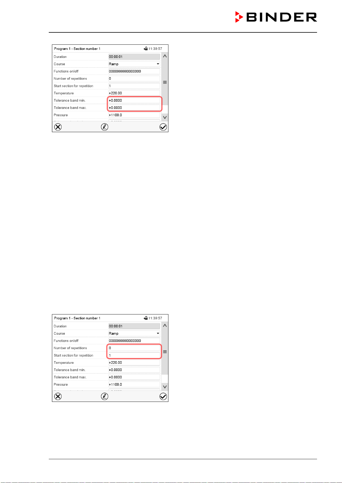
VDL (E3.1) 10/2020 Page 142/196
Section view, showing the temperature tolerance
range
• Select the field “Tolerance band min” and enter the desired lower tolerance band value. Setting range:
-99999 to 99999. Confirm entry with Confirm icon. The controller returns to the section view.
• Select the field “Tolerance band max” and enter the desired upper tolerance band value. Setting range:
-99999 to 99999. Confirm entry with Confirm icon. The controller returns to the section view.
Set the tolerance ranges for other parameters accordingly, if desired.
If one of the actual values (temperature and/or pressure) is outside the program tolerance range the whole
program course is interrupted. During this program interruption time the controller equilibrates to the set-
points of the current section.
The screen header indicates “Program pause (tolerance band)”. The program runtime indication flashes
and does not proceed any further.
When the temperature or pressure values are back within the entered program tolerance range, the pro-
gram continues automatically.
18.7.6 Repeating one or several sections within a time program
You can repeat several subsequent sections together. It is not possible to define the start section the same
time also as the target section, therefore you cannot repeat a single individual section.
Enter the desired number of repetitions in the field “Number of repetitions” and the number of the section
to start the repetition cycle with in the field “Start section for repetition” To have sections repeated infinitely,
enter the number of repetitions as “-1”.
The selected sections are repeated as many times as selected. Then the program continues.
Section view, showing the repetition function
• Select the field “Number of repetitions” and enter the desired number of repetitions. Setting range: 1 to
99, and -1 for infinite. Confirm entry with Confirm icon. The controller returns to the section view.
• Select the field “Start section for repetition” and enter the section number, at which the repetition
should start. Setting range: 1 up to the section before the currently selected section. Confirm entry
with Confirm icon. The controller returns to the section view.
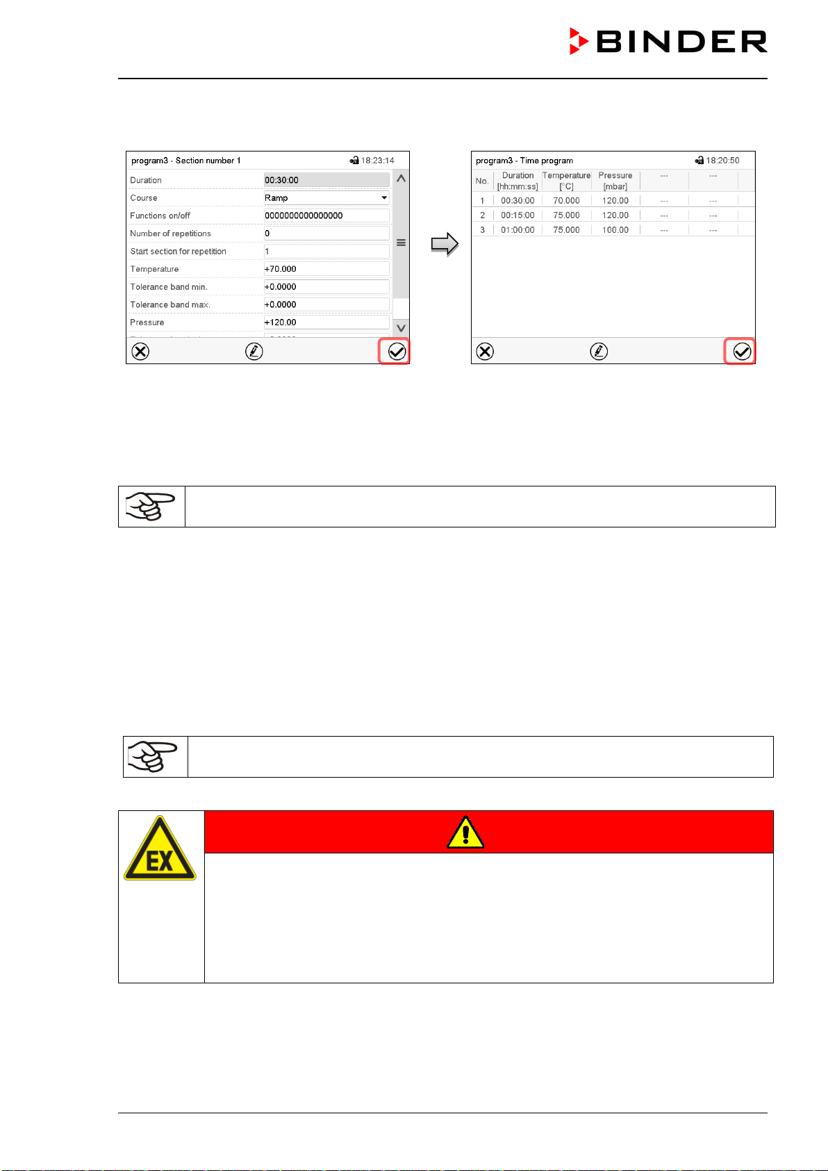
VDL (E3.1) 10/2020 Page 143/196
18.7.7 Saving the time program
Section view (sample values).
After the all desired values of the program
section have been configured, press the Con-
firm icon to take over the programming.
The controller changes to the program view.
Program view (sample program).
Press the Confirm icon to take over the pro-
gramming.
The controller changes to the Normal display.
To save the programming it is absolutely required to press the Confirm icon. Otherwise all
settings will be lost! There is no confirmation prompt!
19. Week programs
The MB2 program controller permits programming week programs with real-time reference. It offers 5 week
program places in total with up to 100 shift points for each week program.
Path: Main menu > Programs> Week program
For each program section you can enter the moment in time, the temperature set-point, the pressure set-
point, and the switching states of the special controller functions.
Before starting the program, check the set-points entered in fixed value mode. After the end
of the program, the set-points will equilibrate to these values.
Solvents and forming vapors can ignite if the drying temperature is too high
DANGER
Fire and explosion hazard when exceeding the auto-ignition temperature of the sol-
vent due to excess drying temperature.
Serious injury or death from burns and / or explosion pressure.
Make sure that only solvents with an auto-ignition temperature that is higher than
200 °C / 392 °F may be entered into the chamber. Check the auto-ignition temperature
with the safety specifications of the solvent. In the case of solvent mixtures, use the
auto-ignition temperature of the material with the lowest auto-ignition temperature.
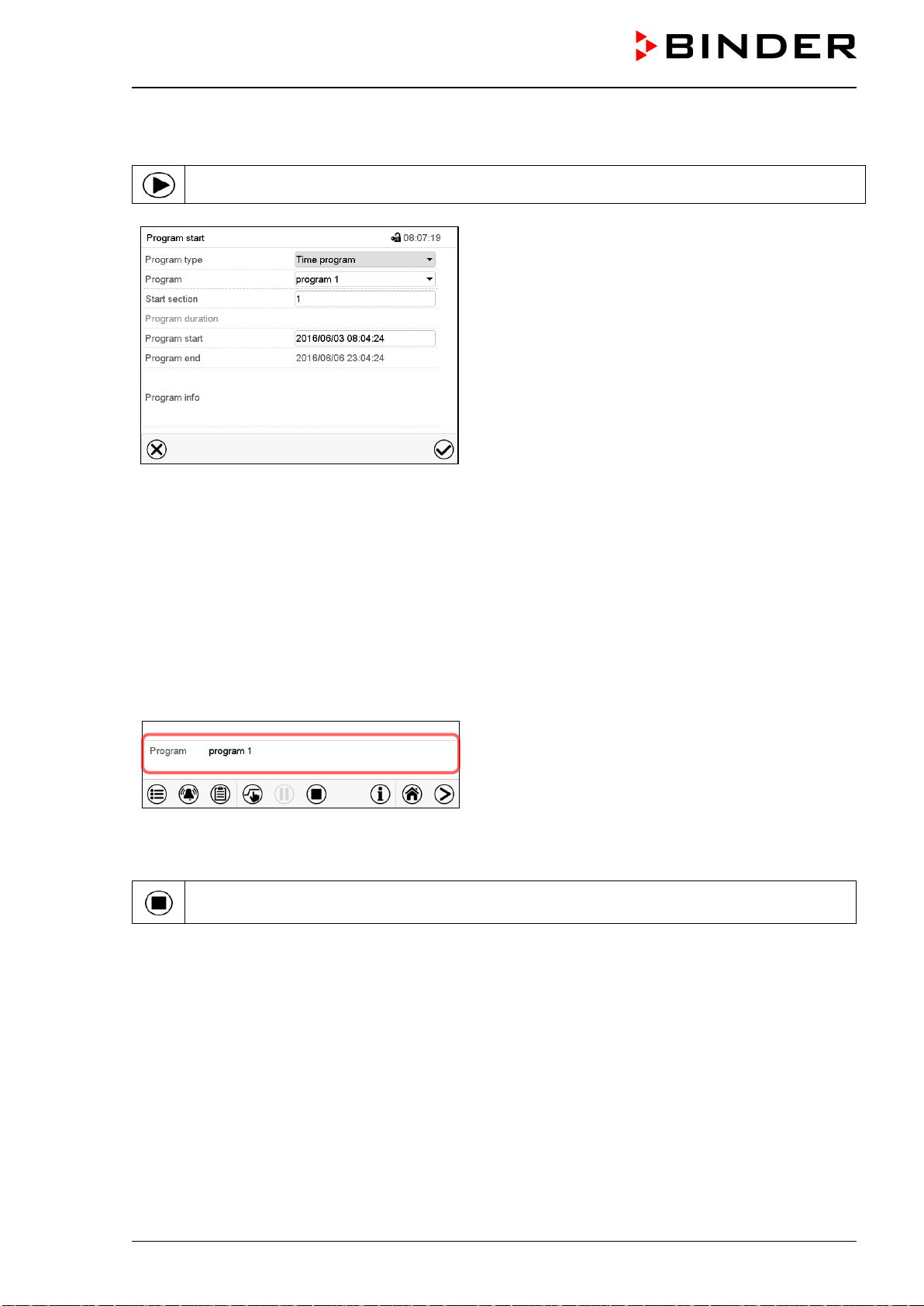
VDL (E3.1) 10/2020 Page 144/196
19.1 Starting an existing week program
In Normal display press the Program start icon to access the “Program start” menu.
“Program start” menu.
• In the field “Program type” select the setting “Week program”.
• In the field “Program” select the desired program.
• There are no further settings available in the “Program start” menu for week programs, as they are
needed only for time programs.
After completing the settings, press the Confirm icon to take over the entries and exit the menu. The pro-
gram starts running.
If instead you press the Close icon to exit the menu without taking over the entries, the program will not
start.
After starting the week program, the previously entered week program setpoints are active and will be
equilibrated according to the current time.
Information on the bottom of the screen indicates the
currently running program.
19.2 Cancelling a running week program
Press the Program cancelling icon to cancel the program.
A confirmation prompt is displayed. Press the Confirm icon to confirm that the program shall really be
cancelled.
After confirming the message, the controller changes to Fixed value operation mode. Temperature and
humidity will then equilibrate to the setpoints of Fixed value operation mode.
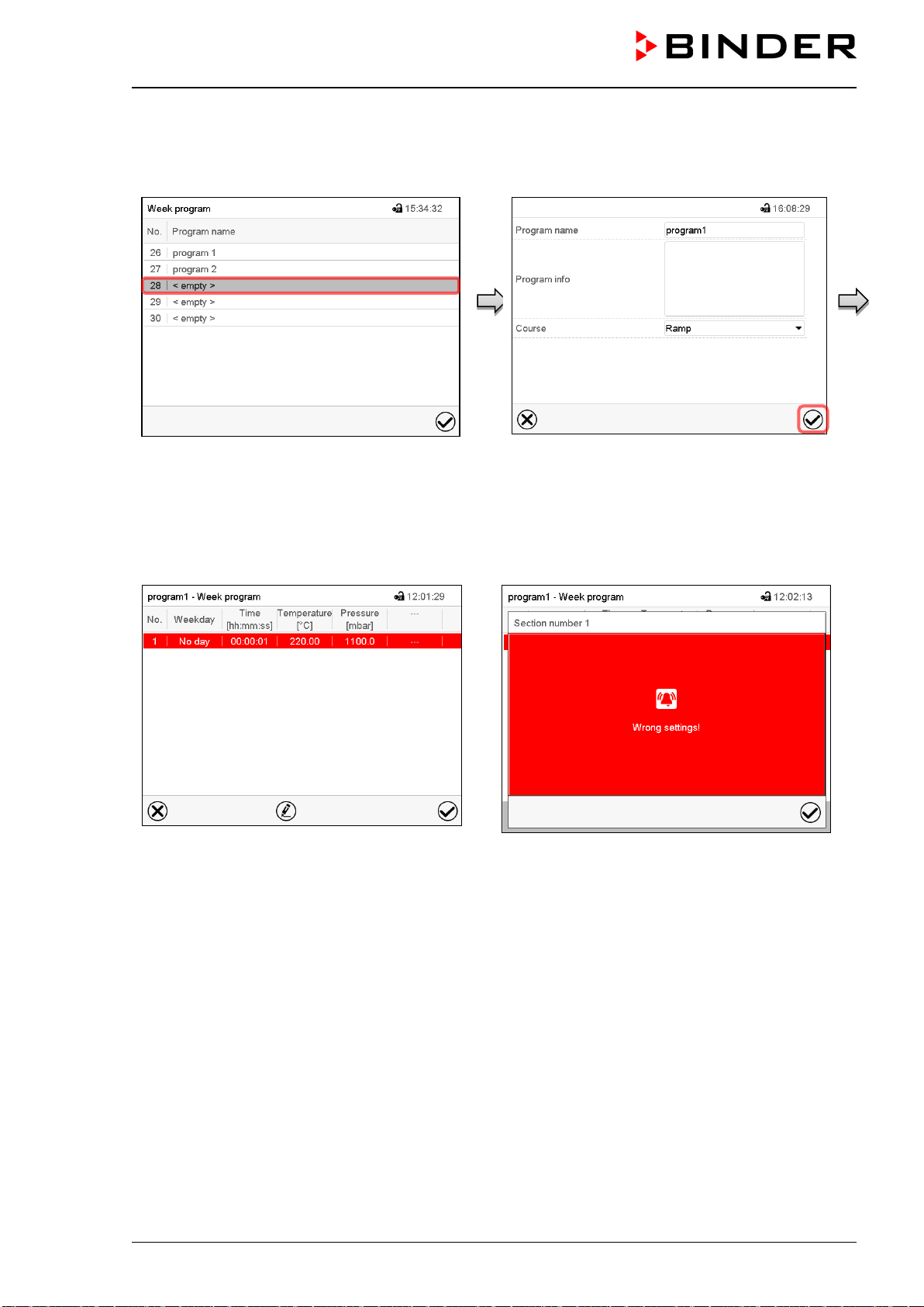
VDL (E3.1) 10/2020 Page 145/196
19.3 Creating a new week program
Path: Main menu > Programs > Week program
“Week program” menu:
overview of the existing programs.
Select an empty program place.
Enter the program name and, if desired, addi-
tional program information in the correspond-
ing fields.
Select the set-point course “Ramp” or “Step”
(chap. 19.6.1).
Press the Confirm icon. The program view
opens.
Program view.
For the first section no weekday is specified.
Therefore the section is first marked in red
and cannot be saved.
Error message when attempting to save the
program
To enter the values, select the program section which is marked in red. You will have access to the Section
view where you can enter the values of the selected section (chap. 19.6).
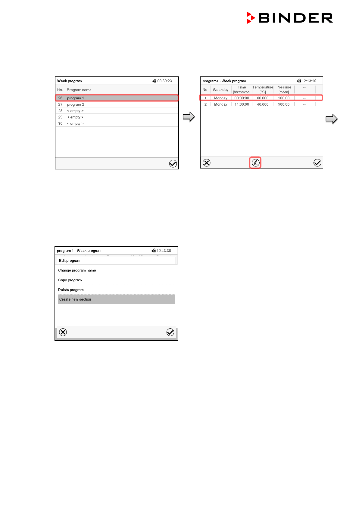
VDL (E3.1) 10/2020 Page 146/196
19.4 Program editor: program management
Path: Main menu > Programs > Week program
“Week program” menu:
overview of the existing programs.
Select an existing program (example: pro-
gram 1).
Program view (example: program 1).
If a new program has been created, there is
just one program section.
There are the following options:
Select a program section to open the sec-
tion editor (chap.
19.5)
Press the Edit icon to open the program
editor
Program editor: “Edit program” menu.
Select the desired function and press the Confirm icon.
The program editor offers following options:
• Change program name. This menu also offers to configure the ramp / step mode setting (chap. 19.6.1).
• Copy program
• Replace program: Replacing a new or an existing program with the copied program. This menu point is
visible only after a section has been copied.
• Delete program
• Create new section
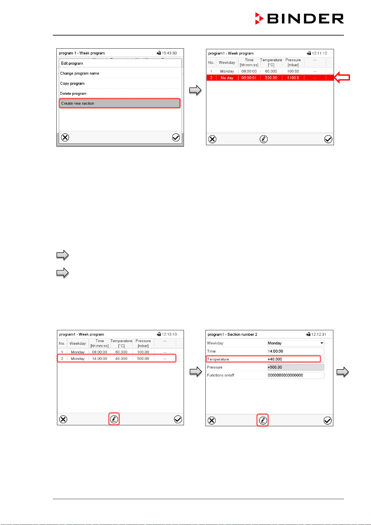
VDL (E3.1) 10/2020 Page 147/196
To add a new section, select “Create new
section” and press the Confirm icon.
The program view opens.
Program view.
With a new section no weekday is specified. There-
fore, the section is first marked in red and cannot be
saved.
A new section is always added at the very bottom
(example: section 3). When the section start is
specified the sections are automatically arranged in
the correct chronological order.
19.4.1 Deleting a week program
Path: Main menu > Programs > Week program
In the “Week program” menu select the program to be deleted. The program view opens.
In the program view press the Edit icon to open the program editor
In the program editor select “Delete program” and press the Confirm icon.
The program is deleted. The controller returns to the program view.
19.5 Section editor: section management
Path: Main menu > Programs > Week program
Select the desired program.
Program view.
Select the desired program section
(example: section 2)
Section view (example: section 2).
There are the following options:
Select a parameter to enter or modify
the according value (chap.
19.6)
Press the Edit icon to open the program
editor
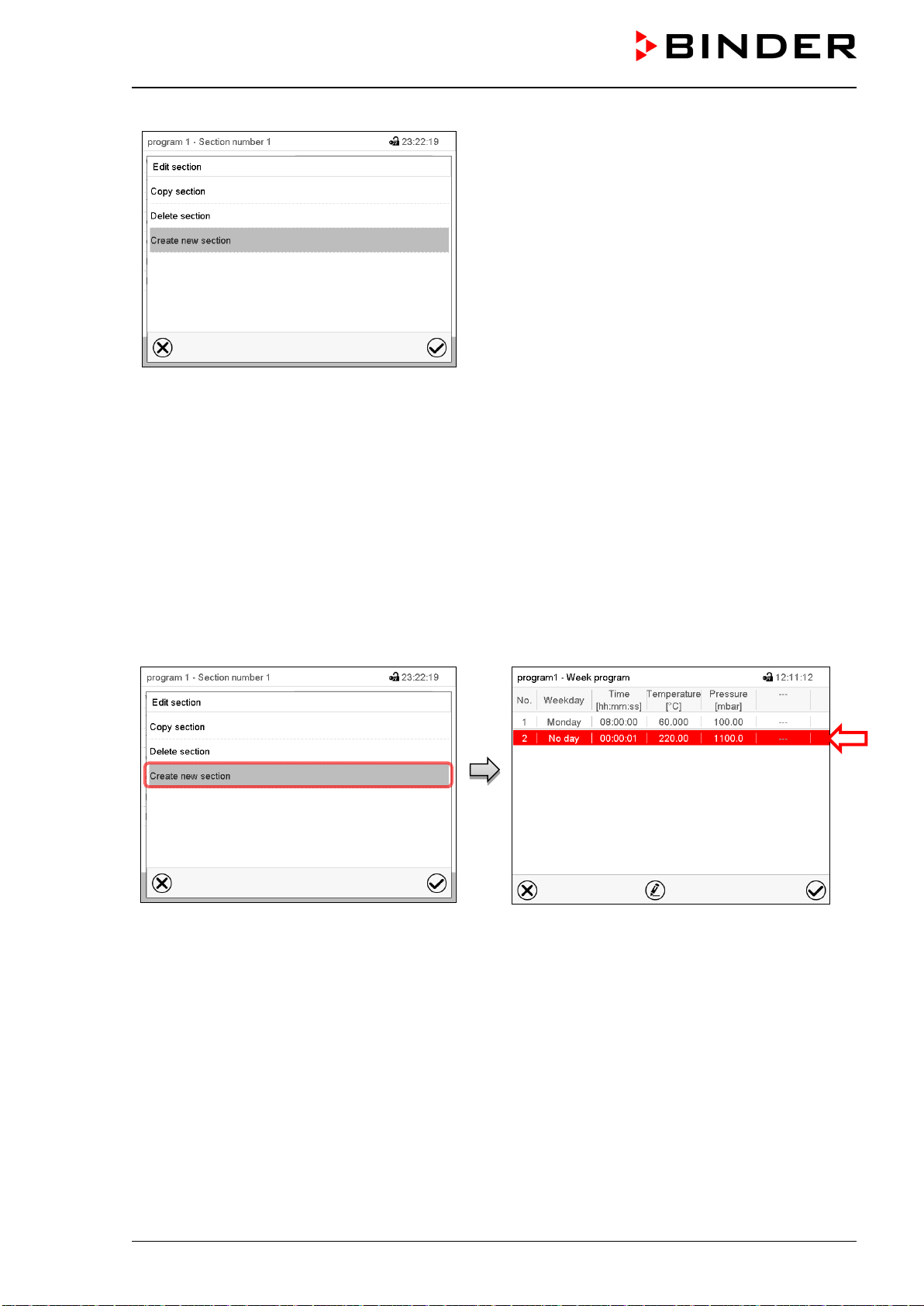
VDL (E3.1) 10/2020 Page 148/196
Section editor: “Edit section” menu
Select the desired function and press the Confirm icon.
The section editor offers following options:
• Copy section
• Replace section: Replacing an existing section with the copied section. This menu point is visible only
after a section has been copied.
• Insert section: Adding the copied section. This menu point is visible only after a section has been copied.
• Delete section
• Create new section
19.5.1 Add a new program section
Section editor: “Edit section” menu.
Select “Create new section” and press the
Confirm icon.
Program view.
With a new section no weekday is specified. There-
fore, the section is first marked in red and cannot be
saved.
A new section is always added at the very bottom
(example: section 3). When the section start is
specified the sections are automatically arranged in
the correct chronological order.
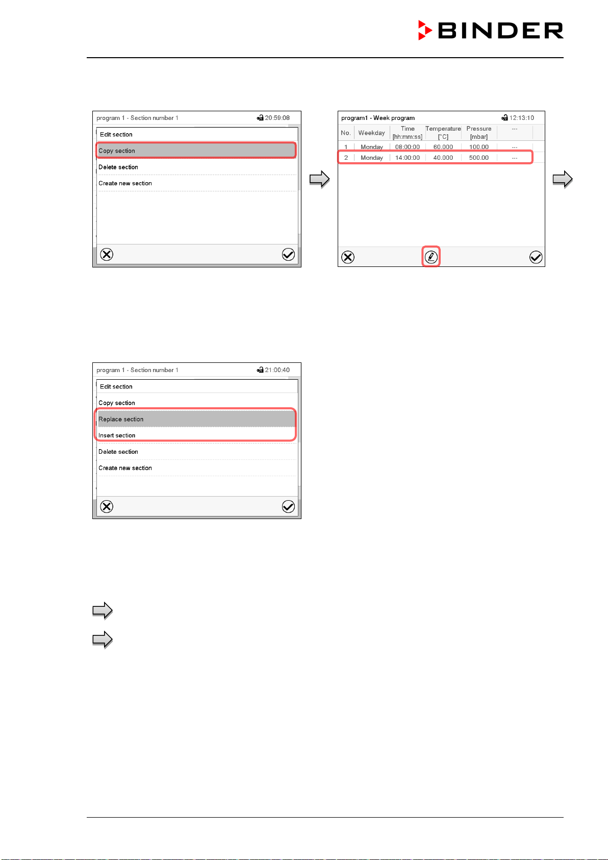
VDL (E3.1) 10/2020 Page 149/196
19.5.2 Copy and insert or replace a program section
Section editor: “Edit section” menu
Select “Copy section” and press the Confirm
icon.
The current section (example: section 1) is
copied.
The controller returns to the program view.
Program view
Select the section to be replaced or before or
after which the copied section shall be in-
serted (example: section 2).
Press the Confirm icon
The controller returns to the section editor
Section editor: “Edit section” menu
Select “Replace section” to replace the selected sec-
tion with the copied section
or
Select “Insert section” to additionally add the copied
section.
Press the Confirm icon.
If you selected “Insert section” the sections are auto-
matically arranged in the correct chronological order.
19.5.3 Deleting a program section
In the program view select the program section to be deleted. The section view opens.
In the section view press the Edit icon to open the section editor
In the section editor select “Delete section” and press the Confirm icon.
The section is deleted. The controller returns to the section view.
19.6 Value entry for a program section in the Section view
Path: Main menu > Programs > Week program
Select the desired program and section.
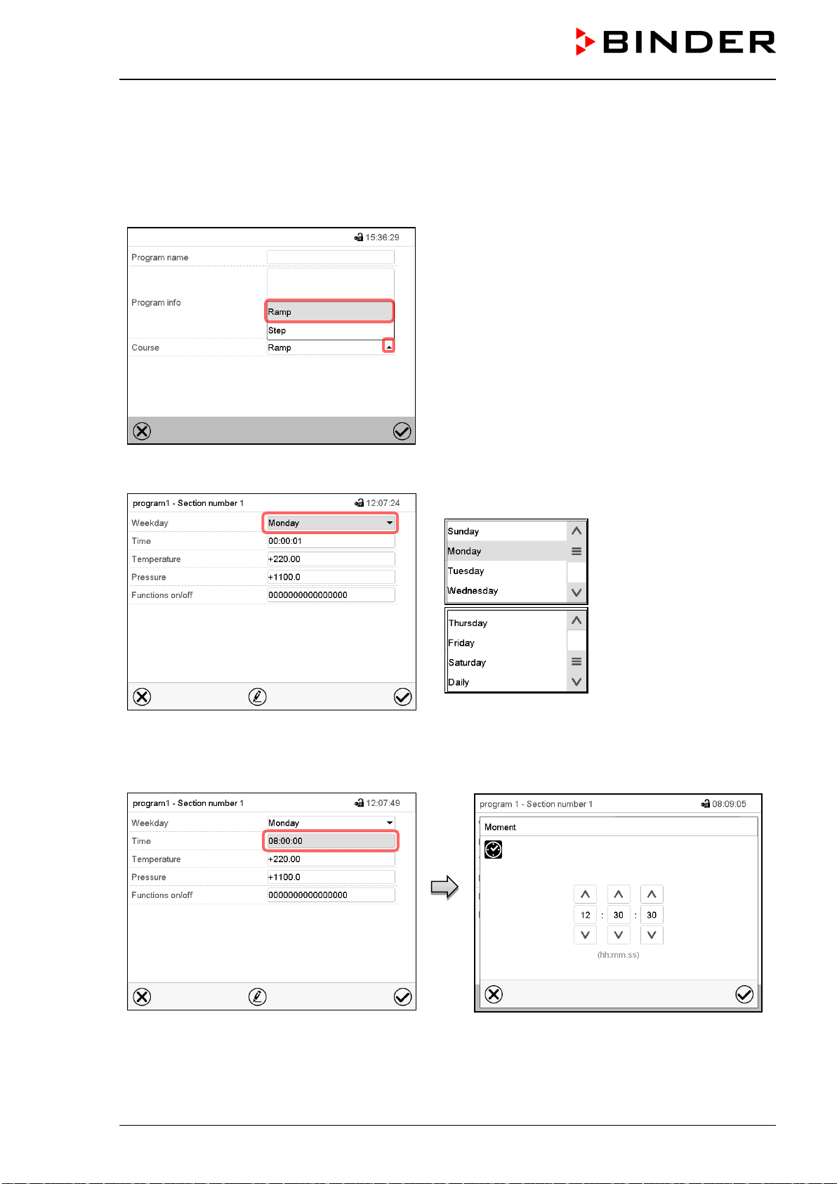
VDL (E3.1) 10/2020 Page 150/196
19.6.1 Set-point ramp and set-point step modes
The explanation of the settings “Ramp” or “Step” is given in chap. 18.7.2.
You can define the type of temperature and pressure transitions for the entire week program.
Select the desired program and press the Edit icon to open the program editor. In the program editor select
the “Change program name” function and press the Confirm icon.
“Change program name” menu.
In the field “Course” select the desired setting
“Ramp” or “Step” and press the Confirm icon.
19.6.2 Weekday
Section view.
In the field “Weekday” select the desired weekday.
With “Daily” selected, this section will run every day
at the same time.
19.6.3 Start time
Section view.
Select the field “Moment”.
Entry menu “Moment”.
Select with the arrow keys the desired start mo-
ment of the section and press the Confirm icon.
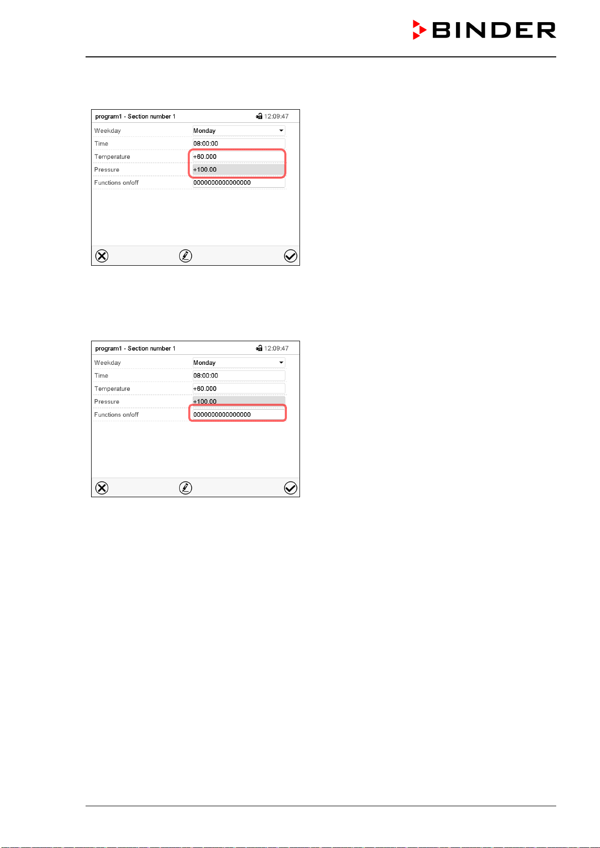
VDL (E3.1) 10/2020 Page 151/196
19.6.4 Setpoint entry
Section view.
• Select the field “Temperature” and enter the de-
sired temperature setpoint.
Setting range: 0.0 °C up to 110.0 °C
Confirm entry with Confirm icon. The controller
returns to the section view.
• Select the field “Pressure” and enter the desired
pressure setpoint.
Setting range: 0 mbar up to 1100 mbar
Confirm entry with Confirm icon. The controller
returns to the section view.
19.6.5 Special controller functions
Section view.
In the “Functions on/off” menu you can define the
switching state of three controller functions.
• Function “Standby” (chap. 9.5)
• Function “GAS/AIR 2” (chap. 11.2)
• Function “Close all valves” (chap. 11.3)
For details please refer to chap. 18.7.3.
After the all desired values of the program section have been configured, press the Confirm icon. The
controller changes to the program view
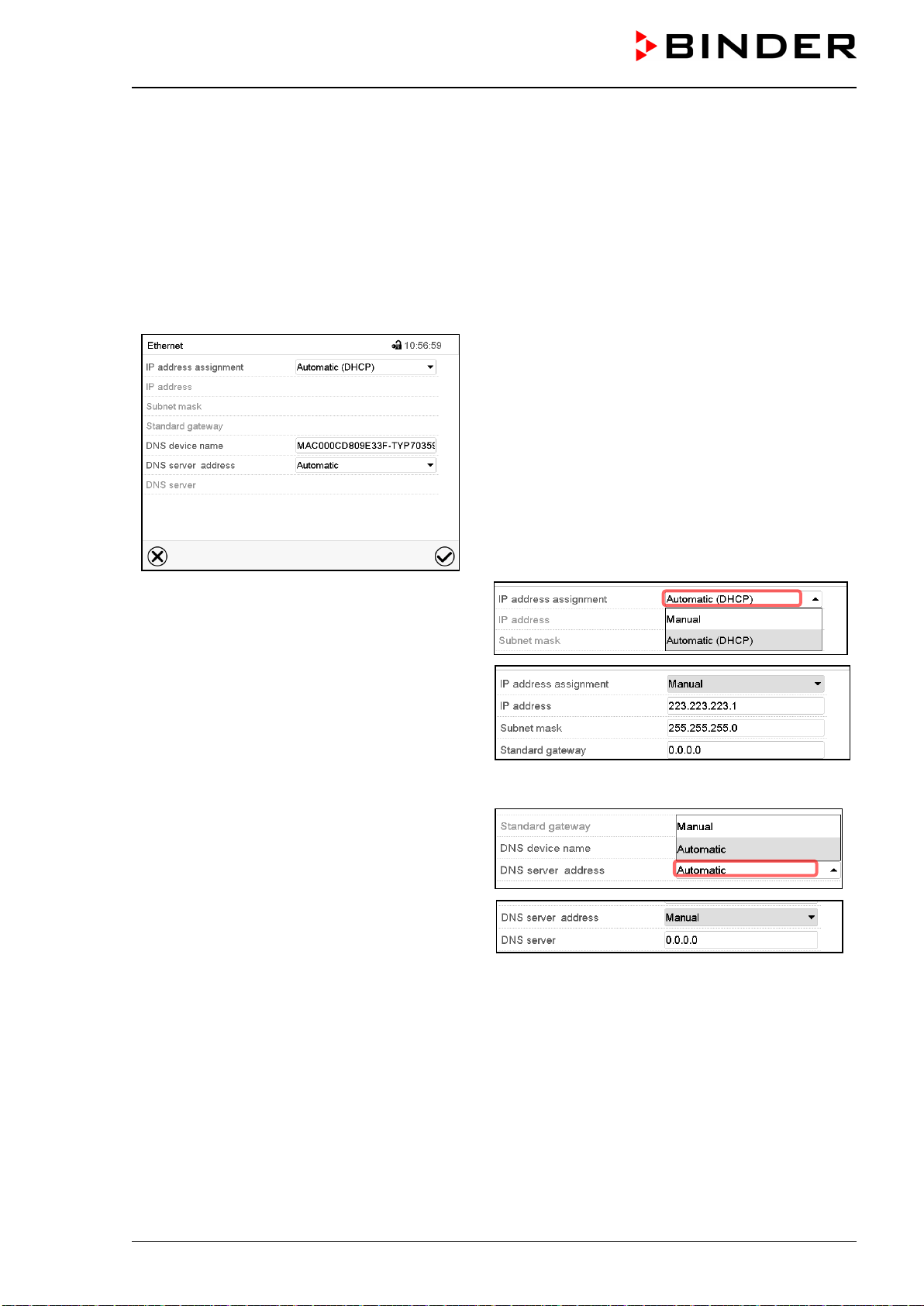
VDL (E3.1) 10/2020 Page 152/196
20. Network and communication
For the network and communication settings at least the “Admin” authorization level is required.
20.1 Ethernet
20.1.1 Configuration
Path: Main menu > Settings > Ethernet
“Ethernet” submenu.
• In the field “IP address assignment” select the
desired setting “Automatic (DHCP)” or “Man-
ual”.
With selection “Manual” you can enter the IP-
address, the subnet mask and the standard
gateway manually.
• Select “DNS device name” and enter the DNS device name. Confirm entry with Confirm icon.
• In the field “DNS server address” select the de-
sired setting “Automatic” or “Manual”.
With selection “Manual” you can enter the DNS
server address manually.
After completing the settings, press the Confirm icon to take over the entries and exit the menu, or press
the Close icon to exit the menu without taking over the entries.
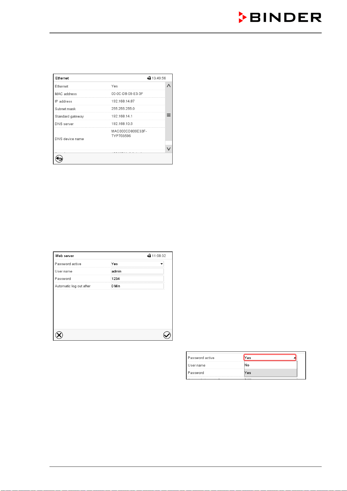
VDL (E3.1) 10/2020 Page 153/196
20.1.2 Display of MAC address
Path: Main menu > Device info > Ethernet
“Ethernet” submenu (example).
20.2 Web server
This controller menu serves to configure the web server. Then you can enter the chamber’s IP-address in
the Internet. The IP address is available via Chamber information > Ethernet. The BINDER web server
opens. Enter the user name and password which have been assigned for the web server in the controller
menu. This enables online access to the controller display, to see e.g., the event list or error messages. In
this view no settings can be changed.
Path: Main menu > Settings > Web server
“Webserver” submenu.
•
In the field “Password active” select the desired
setting “Yes” or “No”.
• Select the field “User name” and enter the desired user name. Confirm entry with Confirm icon.
• Select the field “Password” and enter the desired password. Confirm entry with the Confirm icon.
• Select the field “Automatic log out after” and enter the time in minutes after which the webserver shall
log out automatically. Setting range: 0 min to 65535 min. Confirm entry with Confirm icon.
After completing the settings, press the Confirm icon to take over the entries and exit the menu, or press
the Close icon to exit the menu without taking over the entries.
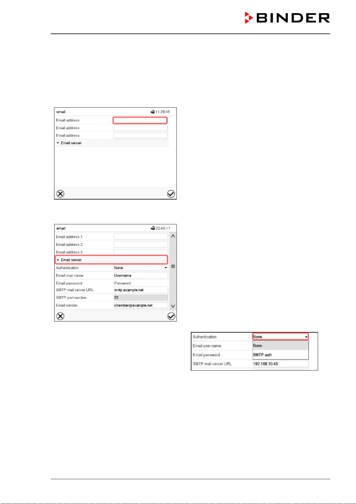
VDL (E3.1) 10/2020 Page 154/196
20.3 E-Mail
As soon as an alarm was triggered, an e-mail is sent to the configured e-mail address.
Path: Main menu > Settings > Email
E-mail address entry:
“Email” submenu.
Select the desired e-mail address field and enter the
e-mail address. You can use the Keyboard change
icon for entry. Confirm entry with Confirm icon.
E-mail server settings:
“Email” submenu.
Select the field “Email server” to access the settings
• In the field “Authentication” select the desired
setting “None” or “SMTP” auth“.
With the setting “SMTP auth”, you can enter a
password under “Email password”.
• Select the field “Email user name” and enter the desired user name. Confirm entry with Confirm icon.
• Select the field “SMTP mail server URL” and enter the SMPT mail server URL. Confirm entry with Con-
firm icon.
• Select the field “SMTP port number” and enter the desired port number. Standard setting: “25”. Confirm
entry with Confirm icon.
• Select the field “Email sender” and enter the desired Email sender. Confirm entry with Confirm icon.
After completing the settings, press the Confirm icon to take over the entries and exit the menu, or press
the Close icon to exit the menu without taking over the entries.
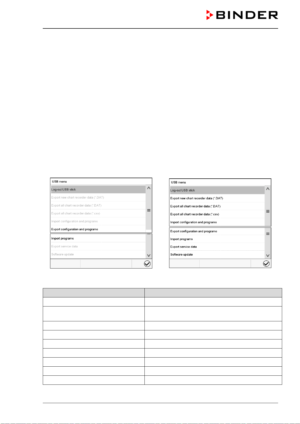
VDL (E3.1) 10/2020 Page 155/196
21. USB menu: Data transfer via USB interface
21.1 Using the USB connection during chamber operation
• Turn the pressure regulator on the chamber rear until the clamping ring touches the lower stop (turn
clockwise. This gives the maximum overpressure.
• Open the USB cover on the controller housing (triangle instrument box)
• Observe the display of the manometer: The overpressure must not drop below 25 Pa (recommendation:
>40 Pa).
• Connect the USB stick.
• If the USB stick remains on the unit for a longer period of time, the pressure can be set to an overpres-
sure of at least 25 Pa (recommendation: >40 Pa) on the pressure regulator.
• Close the USB cover on the controller housing (triangle instrument box)
• Now the pressure regulator can be turned back (counter-clockwise rotation) until the clamping ring
touches the upper stop. (Only tighten to the stop by hand)
The USB port is located in the controller housing (triangle instrument box).
When you insert a USB-stick, the “USB” menu opens. Depending on the user’s authorization level, different
functions (highlighted in black) are available for the logged-in user.
Available functions
with “User” authorization level
Available functions
with “Admin” authorization level
Function Explanation
Log-out USB stick Log-out USB stick bevor pulling it
Export new chart recorder data (*.DAT) Export chart recorder data, which have been added since
last export, in .dat format
Export all chart recorder data (*.DAT) Export all chart recorder data in .dat format
Export all chart recorder data (*.csv) Export all chart recorder data in .csv format
Import configuration and programs Import configuration and timer / time / week programs
Export configuration and programs Export configuration and timer / time / week programs
Import programs Import timer / time / week programs
Export service data Export service data
Software update Controller firmware update
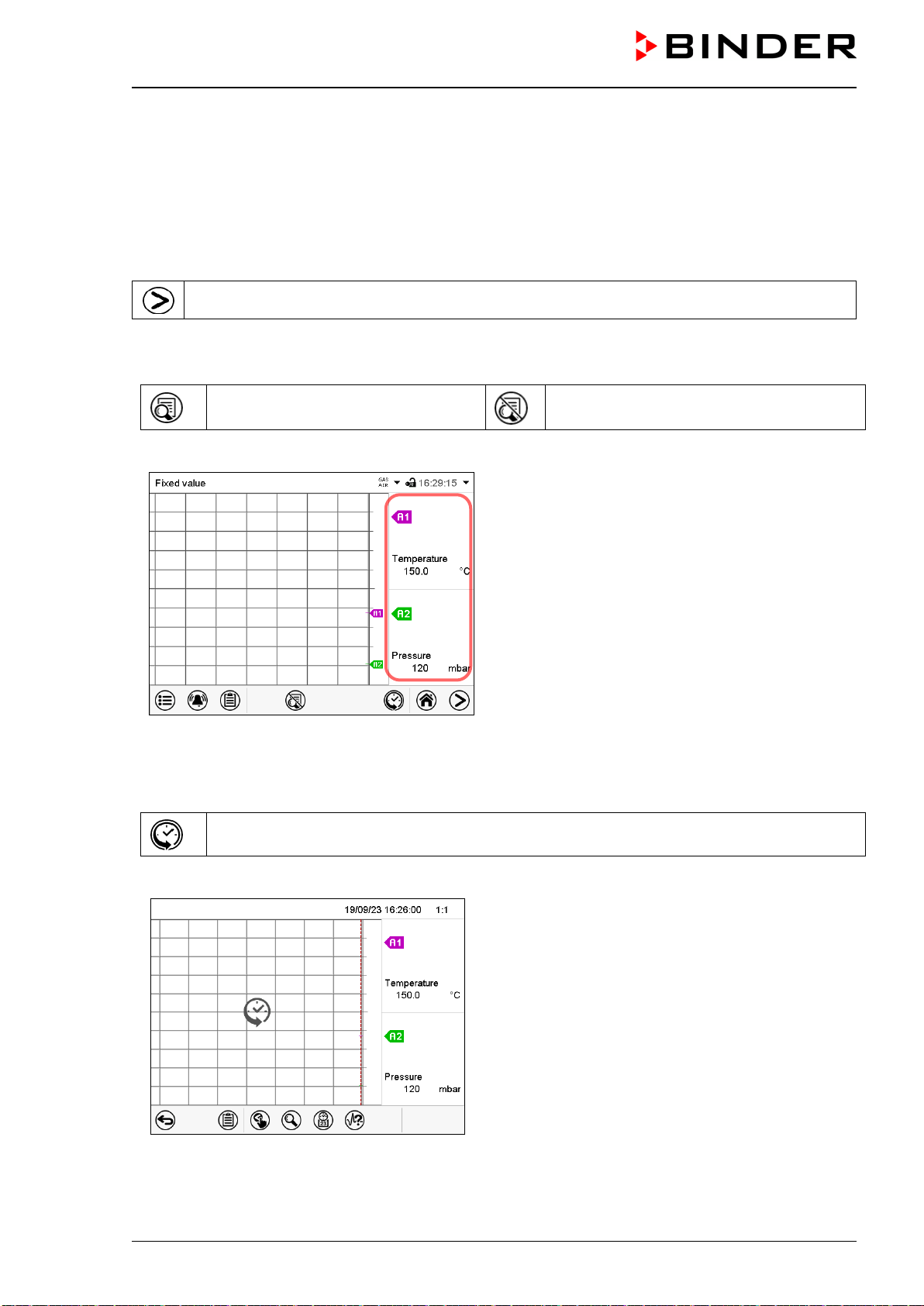
VDL (E3.1) 10/2020 Page 156/196
22. Chart recorder display
This view offers graphic representation of the measurement course. Data representation imitates a chart
recorder and allows recalling any set of measured data at any point of time taken from the recorded period.
22.1 Views
Press the Change view icon to access the pen recorder display.
22.1.1 Show and hide legend
Show legend
Hide legend
Press the Show legend icon to display the legend on the right side of the display
Legend shown on the right side of the display
22.1.2 History display
History display
Press the History display icon to change to the history display.
History display with legend shown.
The chart recorder is paused. Data recording
continues in the background.
Move the central red line by tapping and holding to
the desired position.
The legend at the right side shows the values of the
current line position.
Then further icons appear:
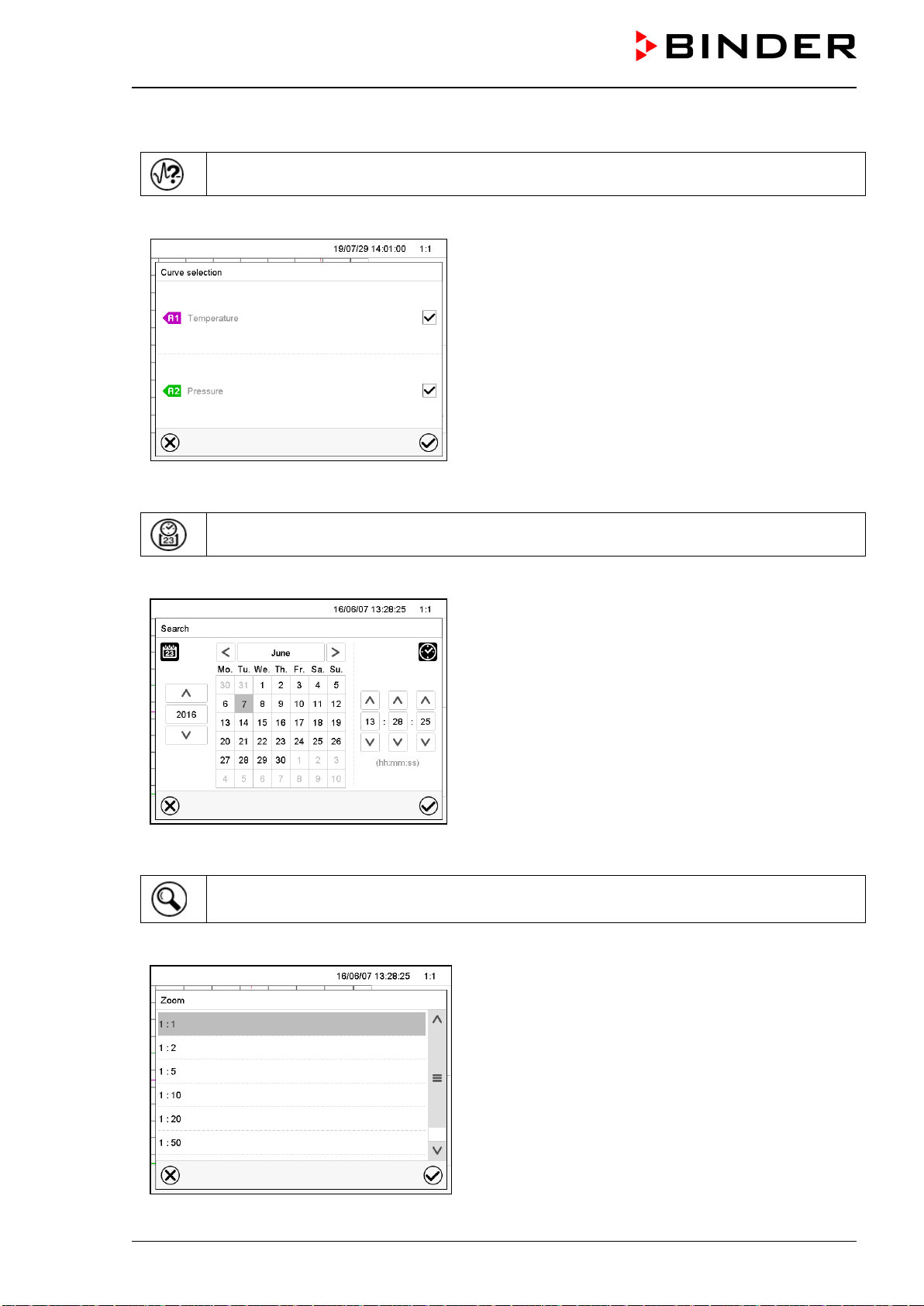
VDL (E3.1) 10/2020 Page 157/196
History display: Curve selection
Curve selection
Press the Curve selection icon to access the “Curve selection” submenu.
“Curve selection” submenu.
Select the curves to be displayed by checking the
checkbox of the corresponding parameter. Press the
Confirm icon
History display: Search the required instant
Search
Press the Search icon to access the “Search” submenu.
“Search” submenu.
Select the required instant by entering its date and
time and press the Confirm icon
History display: Zoom function
Zoom
Press the Zoom icon to access the “Zoom” submenu.
“Zoom” submenu.
Select the zoom factor and press the Confirm icon
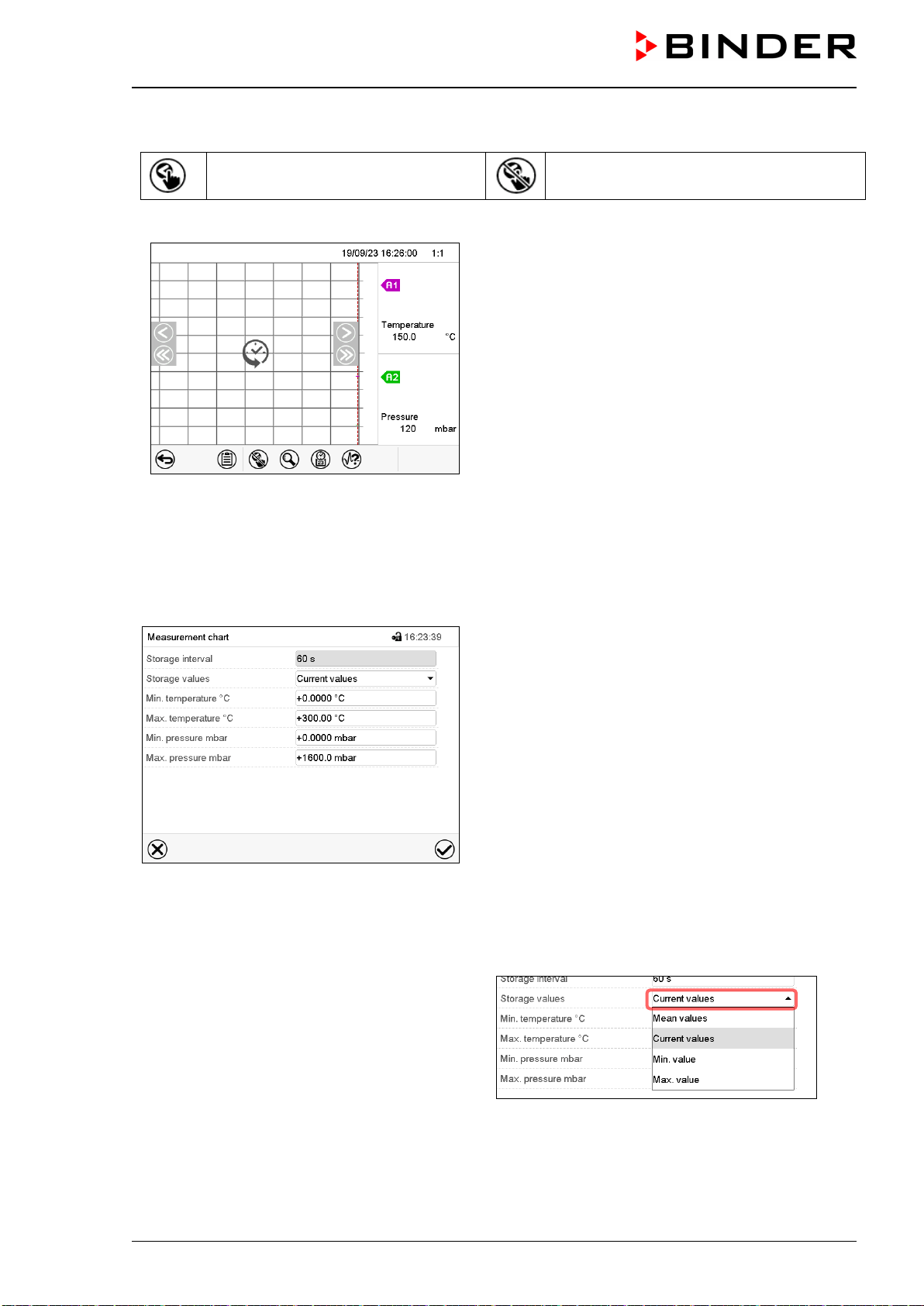
VDL (E3.1) 10/2020 Page 158/196
History display: Show and hide scroll buttons to scroll to an instant
Show scroll buttons
Hide scroll buttons
Press the Show scroll buttons icon to access the “Page selection” submenu.
“Page selection” submenu.
Scroll buttons are shown on the left and on the right.
Use them to move along the timeline.
22.2 Setting the parameters
This menu allows setting the storage interval, the type of values to be shown and the scaling of the tem-
perature and humidity charts.
Path: Main menu > Settings > Measurement chart
“Measurement chart” submenu.
• Select the field “Storage interval” and enter the desired storage interval. Confirm entry with Confirm
icon.
The available presentation depends on the pre-selected storage rate. Factory setting: 60 seconds. This
means the higher the storage rate, the more precisely but shorter the data representation will be.
• In the field “Storage values” select the desired
value type to be displayed.
• For scaling the representation select the desired minimum and maximum temperature or pressure value
and enter the desired values. Temperature display range: 0 °C up to 300 °C. Pressure display range: 0
mbar up to 1600 mbar. Confirm each entry with Confirm icon.
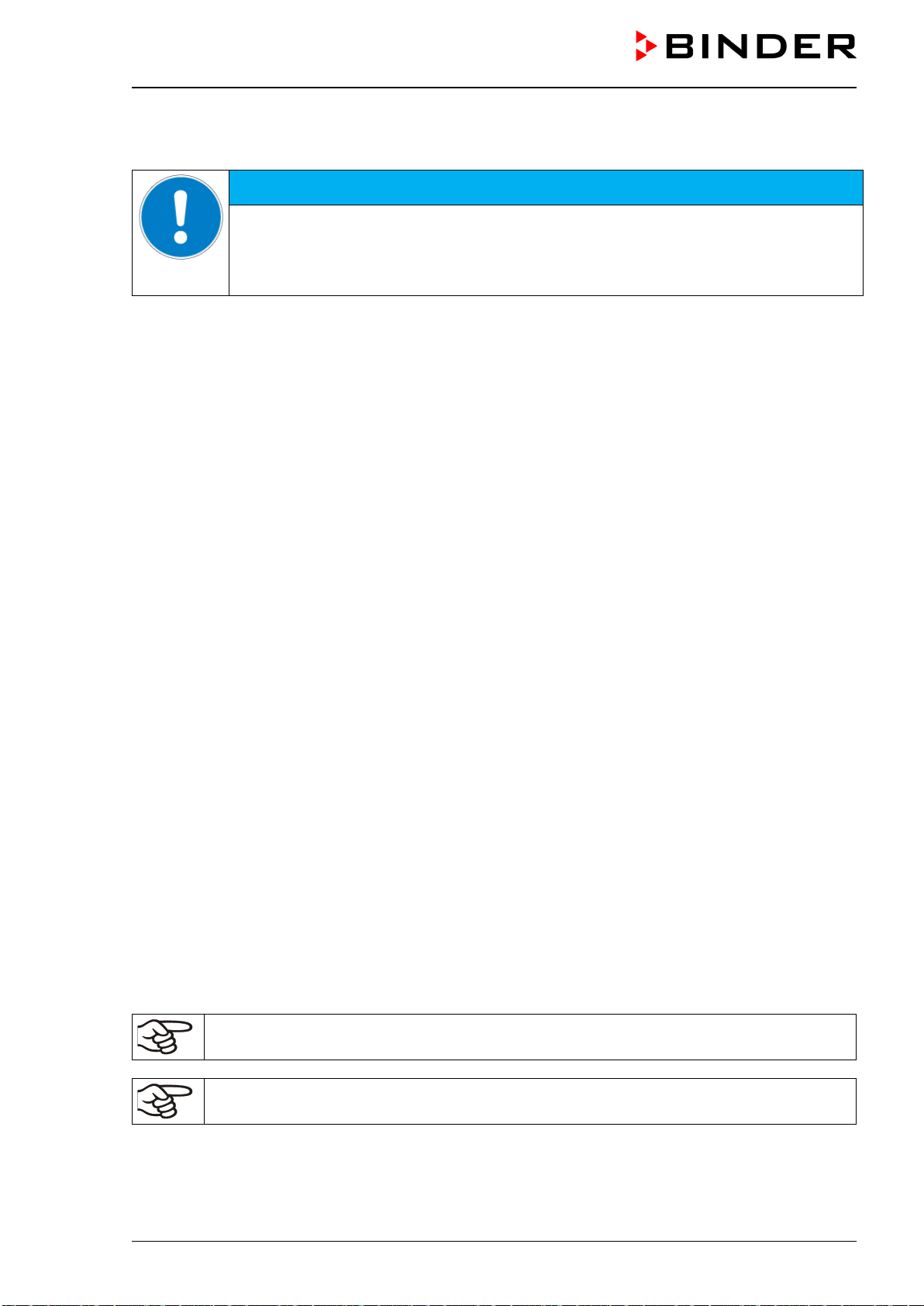
VDL (E3.1) 10/2020 Page 159/196
Setting the storage rate or rescaling (minimum and/or maximum) will clear the measured-value memory
and the event list.
NOTICE
Danger of information loss when setting the storage rate or rescaling.
Data loss of measured-value memory and event list.
Change the storage rate or scaling ONLY if the previously registered data is no longer
needed.
After completing the settings, press the Confirm icon to take over the entries and exit the menu, or press
the Close icon to exit the menu without taking over the entries.
23. Reference measurements
23.1 Checking the temperature in the inner chamber
The controller display was adjusted in the factory to the temperature in the center of the usable volume
(chap. 28.1). The sensor probe of the reference measuring device was connected tightly to an expansion
rack positioned in the middle of the chamber.
23.1.1 Checking the controller display
• Conduct the reference sensor into the inner chamber through the measuring port (12). The port must
be largely vacuum tight to enable a typical operation vacuum for the calibration. Use e.g., a silicone plug
with a hole for the sensor wire.
• Fix the sensor to the center of an expansion rack in the middle of the useable volume with adhesive
aluminum tape or thermal conductive paste to ensure sufficient thermal conductivity.
• Perform the measurement in a thermally stable condition with 3 expansion racks and empty oven.
• Equilibrating time: at least 12 hours.
23.1.2 Checking the spatial temperature exactitude
• Fix at least 9 sensor probes on 3 racks with adhesive aluminum tape or thermal conductive paste to
ensure sufficient thermal conductivity
• The distance of the sensor probes to all inner chamber walls must be at least 10% of the corresponding
inner chamber dimension (see DIN 12880:2007).
• Perform the measurement in a thermally stable condition with 3 expansion racks and empty oven.
• Response time: at least 12 hours.
Do NOT use the temperature probe of the reference measurement device without any con-
tact to the expansion rack, i.e., do NOT measure vacuum values!
In case the temperature probe is a thermo element, mount it so it is electrically insulated from
the rack.
If you note an excessive divergence between the controller and reference temperatures, please contact
BINDER Service to calibrate the temperature controller.
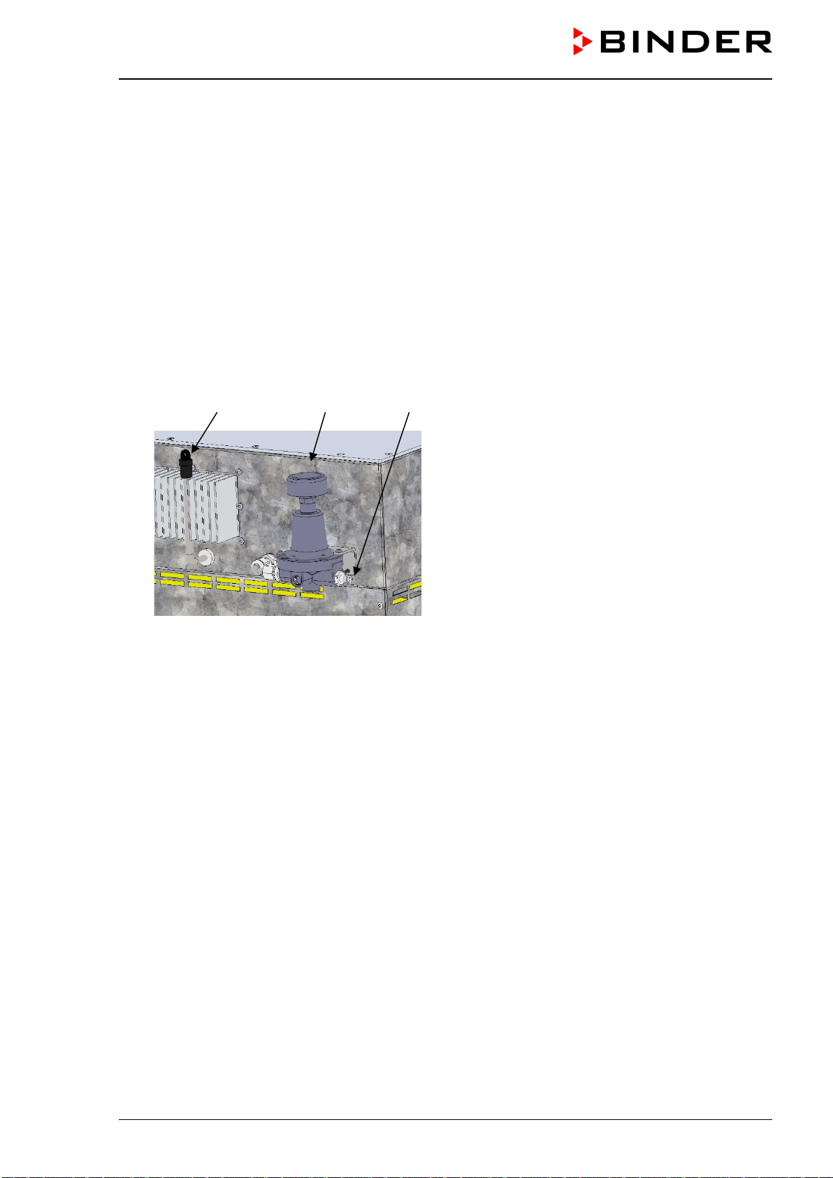
VDL (E3.1) 10/2020 Page 160/196
23.1.3 Checking the function of the manometer for compressed air sweeping
We recommend checking the manometer display for compressed air sweeping in the chamber door at least
once a year.
Via the outlet with sweeping plug for compressed air sweeping before start-up (11), the manometer display
in the door can be tested with a reference manometer.
• Remove the sweeping plug and attach a hose to the tube Ø 8 mm of the outlet (11).
• Open the USB cover on the controller housing (triangular instrument box)
• Use the pressure regulator to set a visible value on the manometer.
• Measure the pressure at the outlet (11) and compare it to the manometer display
The acceptable deviation between the manometer display of the chamber and the reference measuring
device is +/- 10 Pa.
(11) (9) (10)
(9) Pressure regulator for c
ompressed air
sweeping
(10) Connection for compressed air sweeping /
overpressure
(11) Outlet with sweeping plug for compressed
air sweeping before start-up
Figure 26: Pressure regulator and sweeping plug for
compressed air sweeping on the chamber rear
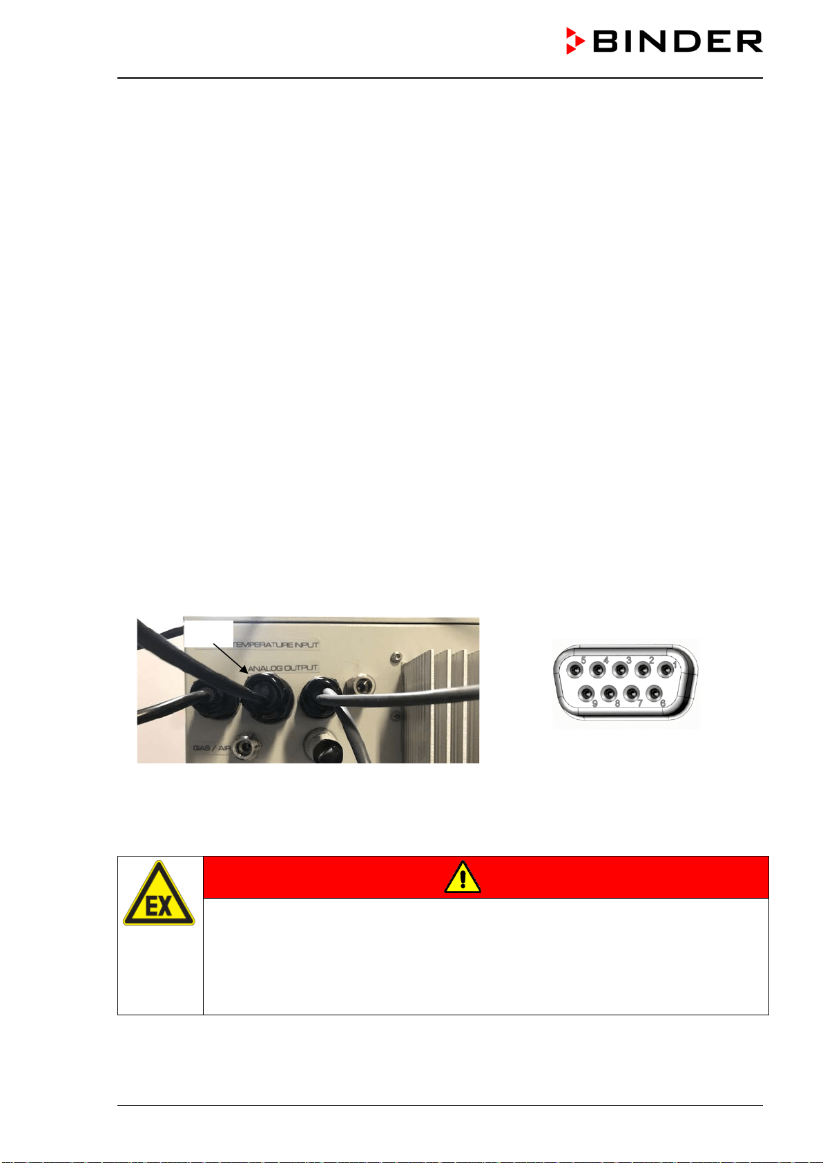
VDL (E3.1) 10/2020 Page 161/196
24. Options
24.1 APT-COM™ 4 Multi Management software (option)
The chamber is regularly equipped with an Ethernet interface (2) that can connect the BINDER APT-COM™
4 Multi Management Software.
The MAC Address is indicated in the “Device info” controller menu (chap. 20.1.2).
The actual temperature and pressure values are given at adjustable intervals. Programming can be per-
formed graphically via PC.
Up to 100 chambers can be cross-linked. For further information please refer to the APT-COM™ 4 operat-
ing manual.
24.2 Analog outputs for temperature and pressure (option)
With this option, the camber is equipped with analog outputs 4-20 mA for temperature and pressure. These
outputs allow transmitting data to external data registration systems or devices.
A 2-meter connection cable is firmly connected to the connection “Analog output” (3b) located in the VDL
rear connection panel. The connection of this cable is realized as a 9-poles SUB-D socket as follows:
ANALOG OUTPUT 4-20 mA DC
PIN 1: Temperature +
PIN 2: Temperature –
PIN 4: Pressure +
PIN 5: Pressure –
Temperature range: 0 °C to +110 °C, pressure range: 0 mbar to 1100 mbar
F
igure 27: Connection cable
on the “Analog output” (3b) connection
Figure 28: SUB-D socket
for the analog outputs option
A suitable plug is enclosed. Please note that the plug connection of the analog output is unprotected and
must therefore be established outside a zone.
DANGER
Explosion hazard due to sparking when disconnecting an electrical connection.
Serious injury or death from burns and / or explosion pressure.
Make sure that the plug connection of the analog output is located outside a zone.
Make sure that the plug connection of the analog output is located outside the installa-
tion area of the VDL and the pump. Take into account the information on zone classifi-
cation (chap. 3.5.2)
(3b)
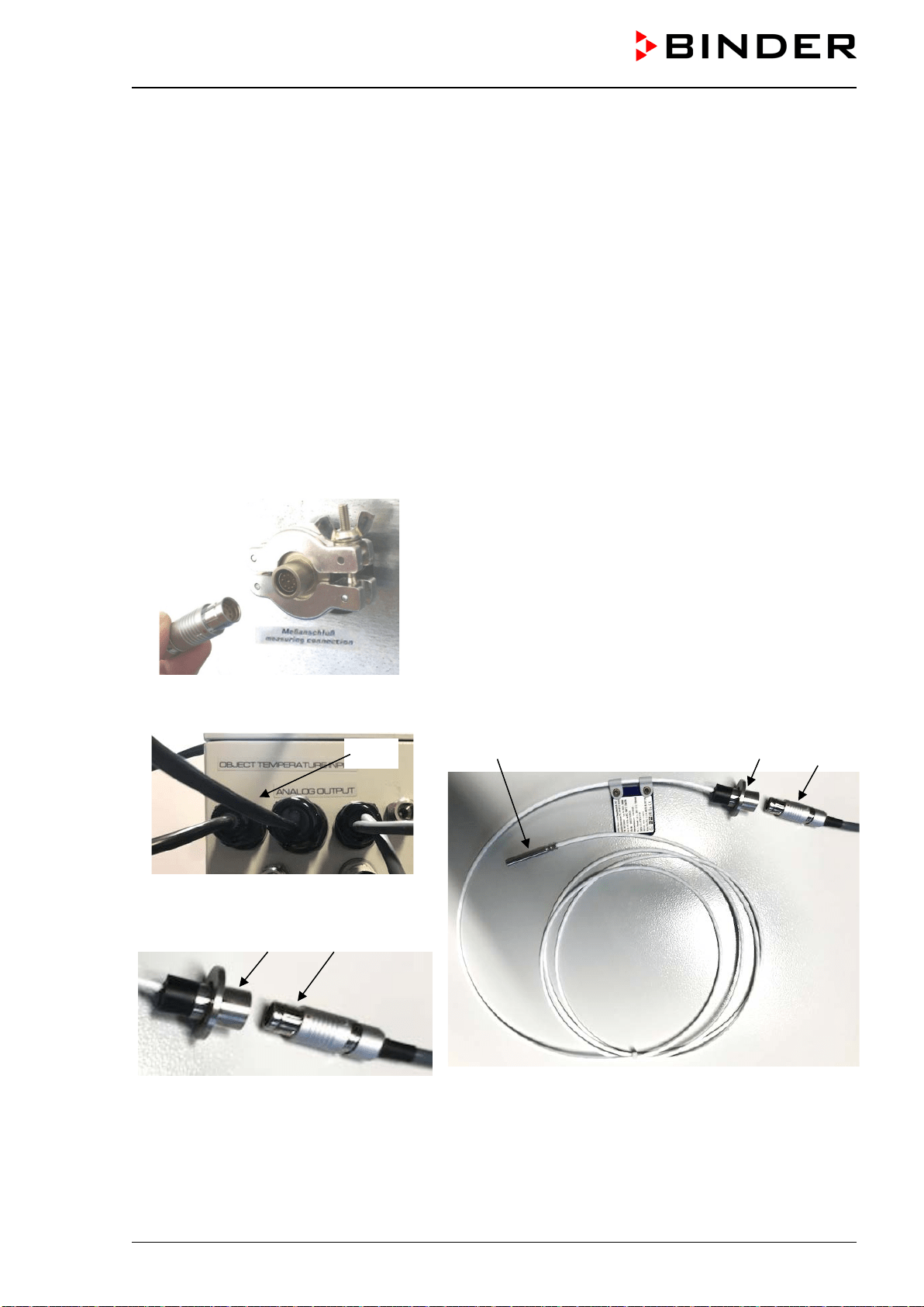
VDL (E3.1) 10/2020 Page 162/196
24.3 Object temperature display with flexible Pt 100 temperature sensor (option)
The object temperature display permits recording the object temperature directly on or in the drying mate-
rial. This enables the determination of the actual temperature of the charging material during the whole
process. The object temperature is measured via a flexible Pt100 sensor inside the inner chamber and can
be viewed on the controller display. The sensor needs to be in thermally conducting contact with the charg-
ing material. It can be plunged into humid charging material up to the length of its protecting tube.
The intrinsically safe connection cable is firmly connected (via an isolation amplifier) to the connection
“Object temperature input” (3a) located in the VDL rear connection panel. This cable connection is realized
as a Lemo socket, which will be connected to a measuring access port on the measuring connection (12)
in the rear panel of the chamber.
24.3.1 Connection of the object temperature sensor
• Insert the Pt 100 temperature sensor from the rear through the measuring connection (12) into the inner
chamber.
• The 3 contacts of the Pt 100 sensor are conducted outside via a measuring access port. For reasons of
explosion protection, this electrical connection to the inner chamber is conducted via a triple internal
safety barrier with a conducting-state voltage of 1.6 Volt maximum against ground.
Technical data of the Pt 100 sensor:
• Three-wire technique
• Class B (DIN EN 60751)
• Temperature range up to 320 °C / 608 °F
• Stainless steel protective tube, length 45 mm / 1.77 in, stain-
less steel material no. 1.4501
Figure 29: Measuring connection (12) with measuring access
port
• Establish a plug connection between the measuring access port and the Lemo socket of the cable
,
w
hich is connected to the connection (3a)
(18) (16) (17)
F
igure 30: Connection cable on the “Object
temperature input” connection (3a)
(16) (17)
Figure 31: Plug connection between meas-
uring access port and Lemo socket
Figure 32: Cable connection of the optional Pt 100 sensor
(16) Measuring access port for Object temperature display
(17) Lemo socket
(18) Pt 100 Temperature sensor
(3a)
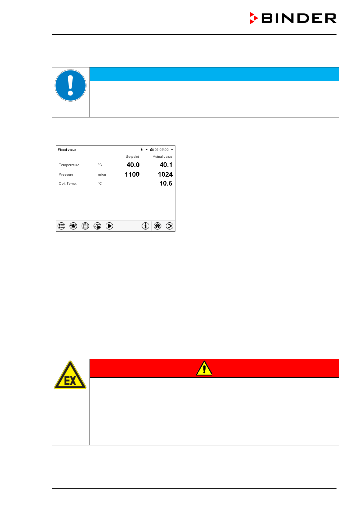
VDL (E3.1) 10/2020 Page 163/196
• For the correct function and temperature display of the device, this plug connection must not be discon-
nected.
NOTICE
Danger of malfunctions by disconnecting the plug connection of the object tempera-
ture display.
Incorrect regulation and display of the temperature.
∅ Do NOT disconnect the plug connection of the object temperature display.
24.3.2 Display on the MB2 controller
Normal display with object temperature display
(sample values)
The object temperature data are put out together with the data of the temperature controller to the cham-
ber’s interface and can be documented by the APT-COM™ 4 Multi Management Software (option, chap.
24.1) developed by BINDER.
25. Cleaning and decontamination
Clean the chamber after each use to avoid potential corrosion damage by ingredients of the charging ma-
terial. .
25.1 Safety instructions on cleaning and decontamination
During cleaning and decontamination, no explosive atmosphere may be present in the installation area of
the chamber and inside the chamber.
DANGER
Fire and explosion hazard due to explosive atmosphere during cleaning and decon-
tamination.
Serious injury or death from burns and / or explosion pressure.
Before performing any cleaning and decontamination measures, make sure that there
is no explosive atmosphere in the installation area of the chamber or inside the cham-
ber.
∅ Do NOT clean the chamber in potentially explosive areas.
Before commissioning, ensure that the system is correctly and completely grounded
VDL (E3.1) 10/2020 Page 164/196
Prior to renewed startup, allow the chamber to completely dry after all cleaning and decontamination
measures.
DANGER
Electrical hazard by water entering the chamber.
Deadly electric shock.
Make sure that the chamber will not become wet during cleaning or decontamination.
∅ Do NOT spill water or cleaning agents over the inner and outer chamber surfaces.
∅ Do NOT put ANY cleaning aids (cloth or brush) into slots or openings on the chamber.
Make sure that no water will enter into slots or openings on the chamber, especially in
the area of the door hinges.
Before cleaning, disconnect the power plug. Let the chamber cool down to ambient
temperature.
Completely dry the chamber before turning it on again.
Avoid electrostatic charges.
DANGER
Explosion hazard due to electrostatic charge when rubbing with a dry cloth.
Serious injury or death from burns and / or explosion pressure.
Use only damp cloth when wiping the device. You may use water and the specified
cleaning agents.
∅ NEVER wipe the device with a dry cloth.
25.2 Cleaning
Disconnect the oven from the power supply before cleaning. Disconnect the power plug.
The interior of the chamber must be kept clean. Thoroughly remove any residues of the
charging material
Wipe the surfaces with a moistened towel. In addition, you can use the following cleaning agents:
Exterior surfaces,
inner chamber,
door gaskets
Standard commercial cleaning detergents free from acid or halides.
Alcohol based solutions.
We recommend using the neutral cleaning agent Art. No. 1002-0016.
Expansion racks,
rack holders
Standard commercial cleaning detergents free from acid or halides, no salt so-
lution or chlorinated solvents.
We recommend using the neutral cleaning agent Art. No. 1002-0016.
Controller housing (tri-
angular instrument box)
Standard commercial cleaning detergents free from acid or halides.
We recommend using the neutral cleaning agent Art. No. 1002-0016.
Zinc coated hinge parts
rear chamber wall
Standard commercial cleaning detergents free from acid or halides.
Do NOT use a neutral cleaning agent on zinc coated surfaces.
Do not use cleaning agents that may cause a hazard due to reaction with components of the device or the
charging material. If there is doubt regarding the suitability of cleaning products, please contact BINDER
service.
VDL (E3.1) 10/2020 Page 165/196
We recommend using the neutral cleaning agent Art. No. Art. 1002-0016 for a thorough
cleaning.
Any corrosive damage that may arise following use of other cleaning agents is excluded from
liability by BINDER GmbH.
Any corrosive damage caused by a lack of cleaning, is excluded from liability by BINDER
GmbH.
NOTICE
Danger of corrosion by using unsuitable cleaners.
Damage to the chamber.
∅ Do NOT use acidic or chlorine cleaning detergents.
∅ Do NOT use a neutral cleaning agent on other kind of surfaces e.g., the zinc coated
hinge parts or the rear chamber wall.
For surface protection, perform cleaning as quickly as possible.
After cleaning completely remove cleaning agents from the surfaces with a moistened towel.
Let the chamber dry.
Soapsuds may contain chlorides and must therefore NOT be used for cleaning.
With every cleaning method, always use adequate personal safety controls.
Following cleaning, leave the chamber door open or remove the access port plugs.
The neutral cleaning agent may cause health problems in contact with skin and if ingested.
Follow the operating instructions and safety hints labeled on the bottle of the neutral clean-
ing agent.
Recommended precautions: To protect the eyes use sealed protective goggles. Suitable protective gloves
with full contact: butyl or nitrile rubber, penetration time >480 minutes.
CAUTION
Danger of chemical burns due to contact with skin or ingestion of the
neutral cleaning agent.
Skin and eye damage. Environmental damage.
∅ Do NOT empty the neutral cleaning agent into drains.
∅ Do not ingest the neutral cleaning agent. Keep it away from food and bev-
erages.
Wear protective gloves and goggles.
Avoid skin contact with the neutral cleaning agent.
25.3 Decontamination / chemical disinfection
The operator must ensure that proper decontamination is performed in case a contamination of the cham-
ber by hazardous substances has occurred.
Disconnect the chamber from the power supply prior to chemical decontamination. Disconnect the power
plug.
VDL (E3.1) 10/2020 Page 166/196
Do not use decontamination agents that may cause a hazard due to reaction with components of the device
or the charging material. If there is doubt regarding the suitability of cleaning products, please contact
BINDER service.
You can use the following disinfectants:
Inner chamber Standard commercial surface disinfectants free from acid or halides.
Alcohol based solutions.
We recommend using the disinfectant spray Art. No. 1002-0022.
For chemical disinfection, we recommend using the disinfectant spray Art. No. 1002-0022.
Any corrosive damage that may arise following use of other disinfectants is excluded from lia-
bility by BINDER GmbH.
With every decontamination / disinfection method, always use adequate personal safety con-
trols.
In case of contamination of the interior by biologically or chemically hazardous material, proceed as follows:
Remove the vacuum expansion racks and removable rack holders and spray the inner chamber with an
appropriate disinfectant.
If desired you can sterilize the vacuum expansion racks and removable rack holders in a sterilizer or auto-
clave. Before start-up, the chamber must be absolutely dry and ventilated, as explosive gases may form
during the decontamination process.
In case of eye contact, the disinfectant spray may cause eye damage due to chemical
burns. Follow the operating instructions and safety hints labeled on the bottle of the disin-
fectant spray.
Recommended precautions: To protect the eyes use sealed protective goggles.
CAUTION
Danger of chemical burns due to eye contact with desinfactants.
Eye damage. Environmental damage.
∅ Do NOT empty desinfactants into drains.
Wear protective goggles.
After using the disinfectant spray, allow the chamber to dry thoroughly, and aerate it suffi-
ciently.
VDL (E3.1) 10/2020 Page 167/196
26. Maintenance and service, troubleshooting, repair, testing
DANGER
Fire and explosion hazard due to explosive atmosphere during maintenance and ser-
vice, troubleshooting, repair, and testing.
Serious injury or death from burns and / or explosion pressure.
Before performing troubleshooting, maintenance or repair work, make sure that there is
no explosive atmosphere in the installation area of the chamber or inside the chamber
∅ Do NOT perform any maintenance, repair or tests on the chamber in potentially explo-
sive areas.
Conduct the explosion protection test when performing the annual maintenance and af-
ter repair.
∅ Do NOT put the chamber into operation if it did not pass the explosion protection test.
Before commissioning, ensure that the system is correctly and completely grounded.
26.1 General information, personnel qualifications
• Maintenance
Please refer to chap. 26.3
• Simple troubleshooting
Chap. 26.2. describes troubleshooting by operating personnel. It does not require technical intervention
into the chamber, nor disassembly of chamber parts
For personnel requirements please refer to chap. 1.1
• Detailed troubleshooting
If errors cannot be identified with simple troubleshooting, further troubleshooting must be performed by
BINDER Service or by BINDER qualified service partners or technicians, in accordance with the de-
scription in the VDL Service Manual.
For personnel requirements please refer to the Service Manual.
• Repair
Repair of the chamber can be performed by BINDER Service or by BINDER qualified service partners
or technicians, in accordance with the description in the VDL Service Manual.
After maintenance, the chamber must be tested prior to resuming operation. An electrical test and an
explosion protection test are required.
• Electrical testing
To prevent the risk of electrical shock from the electrical equipment of the chamber, an annual repeat
inspection as well as a test prior to initial startup and prior to resuming operation after maintenance or
repair, are required. This test must meet the requirements of the competent public authorities. We rec-
ommend testing under DIN VDE 0701-0702:2008 in accordance with the details in the Service Manual.
For personnel requirements please refer to the Service Manual.
• Test for explosion protection
Testing before initial commissioning and before restarting after maintenance or repair as well as repeat
tests according to the explosion protection concept created by the operator is required.
Observe the relevant legal regulations for the qualification of the examiner. In Germany, the explosion
protection test may only be carried out by a qualified person recognized by a state authority or by
the manufacturer (BINDER Service).
VDL (E3.1) 10/2020 Page 168/196
26.2 Simple troubleshooting
DANGER
Fire and explosion hazard due to explosive atmosphere during troubleshooting.
Serious injury or death from burns and / or explosion pressure.
Before performing a simple troubleshooting, make sure that there is no explosive at-
mosphere in the installation area of the chamber or inside the chamber.
Defects and shortcomings can compromise the operational safety of the chamber and can lead to risks and
damage to equipment and persons. If there are is a technical fault or shortcoming, take the chamber out of
operation and inform BINDER Service. If you are not sure whether there is a technical fault, proceed ac-
cording to the following list. If you cannot clearly identify an error or there is a technical fault, please contact
BINDER Service.
Only qualified service personnel authorized by BINDER must perform repair.
Repaired chambers must comply with the BINDER quality standards and pass the required
tests.
Fault description
Possible cause
Required measures
General
Chamber permanently turned
off.
No power supply.
Check connection to power supply.
Wrong voltage.
Check power supply for voltage of
115V or 230V.
Chamber fuse has responded.
Check chamber fuse.
Controller defective.
Contact BINDER Service.
Heating
Chamber doesn’t heat up.
Pressure threshold of 100 mbar
not reached. No heater release.
Wait until pressure threshold is
reached and heater released.
Select suitable pressure setpoint.
Chamber door not properly
closed.
Completely close chamber door.
Door gasket defective.
Replace door gasket,
Pt 100 sensor defective.
Contact BINDER service.
Heating element defective.
Semiconductor relay defective
Chamber doesn’t heat up.
Alarm message “Safety control-
ler” on the controller display
Safety controller has responded:
Inner chamber temperature has
reached the safety controller
value. Safety controller value set
too low or temperature set-point
too high, or error in the heating
system.
Let the chamber cool down.
Acknowledge the alarm on the con-
troller. Check the settings of the
temperature setpoint and safety
controller value. If appropriate, se-
lect suitable safety controller value
(chap. 14.2).
Safety controller defective.
Contact BINDER service.
Chamber doesn’t heat up.
Alarm message “Overtempera-
ture” on the controller display
Safety temperature limiter (TL)
has turned off the heater. Cham-
ber defective.
Let the chamber cool down.
Acknowledge the alarm on the con-
troller and restart the chamber (re-
connect power plug). If the error re-
peats, turn off the chamber and
contact BINDER service.
Set-point temperature is not
reached after specified time.
Chamber door not properly
closed.
Completely close chamber door.
Door gasket defective.
Replace door gasket,
Controller not adjusted.
Calibrate and adjust controller.
VDL (E3.1) 10/2020 Page 169/196
Fault description
Possible cause
Required measures
Heating (continued)
Chamber heating permanently,
set-point not maintained.
Controller defective.
Contact BINDER service
Pt 100 sensor defective.
Semiconductor relay defective
Controller not adjusted.
Calibrate and adjust controller.
Deviations from the indicated
heating-up times.
Oven fully loaded.
Charge the oven less or consider
longer heating-up times.
Deviations from the temperature
set-point in equilibrated state.
Invalid calibration
Use the delivered expansion racks
only. Do NOT change between alu-
minum and stainless-steel racks
Wrong temperature value meas-
ured during calibration
Reference temperature sensor
has insufficient contact to expan-
sion rack.
Fix the reference temperature sen-
sor with thermal conductive paste
or adhesive aluminum tape.
Leakage current when using a
thermo element not electrically
isolated.
Mount a thermo element electrically
isolated from the rack.
Vacuum
Vacuum not held.
Door gasket defective.
Replace door gasket,
Safety glass panel defective.
Replace safety glass panel.
Gaskets of small flange connec-
tions (universal eccentric ring)
defective.
Replace gaskets of small flange
connections.
Inner tube connection leaky.
Contact BINDER Service.
Controller
No chamber function
(dark display).
Chamber is in standby mode.
Deactivate standby mode (chap.
9.5).
Menu functions not available.
Menu functions not available
with current authorization level.
Log in with the required higher au-
thorization.
Log in with the required higher au-
thorization. or contact BINDER ser-
vice to obtain an activation code
(chap. 12.6).
No access to controller
Incorrect password.
Contact BINDER service.
Controller does not equilibrate to
entered setpoints.
Temperature control is turned
off
Turn on temperature control (chap.
11.4).
Pressure control is turned off.
Turn on pressure control (chap.
11.5).
Set-points were entered in
Fixed value operation mode.
Controller is in program opera-
tion mode.
Change to Fixed value operation
mode.
Pressure alarm when operating
without a vacuum connection.
Pressure control turned on.
Turn off pressure control (chap.
11.5).
Acknowledging the alarm does
not cancel the alarm state.
Cause of alarm persists.
Remove cause of alarm. If the alarm
state continues, contact BINDER
service.
Alarm message:
- - - - or <-<-< or >->->
Sensor rupture between sensor
and controller or Pt 100 sensor
defective.
Contact BINDER service.
Short-circuit.
VDL (E3.1) 10/2020 Page 170/196
Fault description
Possible cause
Required measures
Controller (continued)
Measured-value memory
cleared in Chart recorder func-
tion, information lost.
New setting of storage rate or
scaling (minimum and/or maxi-
mum) (chap. 22.2).
Change the storage rate or scaling
ONLY if the previously registered
data are no longer required.
Program does not run correctly
after starting it.
Pressure threshold of 100 mbar
not reached. No heater release
Wait until pressure threshold is
reached and heater released. Start
program after this or set suitable toler-
ance limits.
If appropriate, select suitable pres-
sure setpoint.
Controller does not equilibrate
to program set-points.
Controller is not in program op-
eration mode, or program delay
time is running.
Start the program again. If appropri-
ate, wait for the program delay time.
Program duration longer than
programmed.
Tolerances have been pro-
grammed.
For rapid transition phases, do NOT
program tolerance limits in order to
permit maximum heating, evacuating,
or ventilation speed.
Program keeps the last pro-
gram setpoint constant while in
setting “ramp”.
Program line with setting “ramp”
is incomplete.
When programming with setting
“ramp”, define the end value of the
desired cycle by adding an additional
section with a section time of at least
one second.
Ramp temperature transitions
are only realized as steps.
Setting “step” has been se-
lected.
Select setting “ramp”.
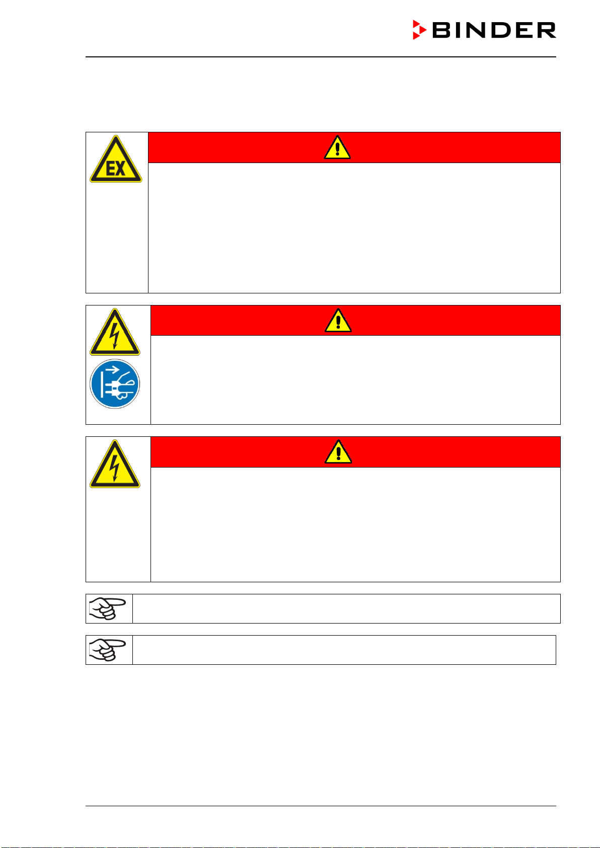
VDL (E3.1) 10/2020 Page 171/196
26.3 Maintenance, Service
26.3.1 Safety instructions on maintenance work
DANGER
Fire and explosion hazard due to explosive atmosphere during maintenance .
Serious injury or death from burns and / or explosion pressure.
Before performing maintenance work, make sure that there is no explosive atmosphere
in the installation area of the chamber or inside the chamber.
∅ Do NOT perform any maintenance or tests on the chamber in potentially explosive ar-
eas s.
Conduct the explosion protection test when performing the annual maintenance.
∅ Do NOT put the chamber into operation if it did not pass the explosion protection test.
Before commissioning, ensure that the system is correctly and completely grounded.
DANGER
Electrical hazard during live maintenance work.
Deadly electric shock.
Disconnect the chamber before conducting maintenance work. Pull the power plug.
∅ Do NOT remove the rear panel of the chamber.
Make sure that general maintenance work will be conducted by licensed electricians
with additional skills in explosion protection (ATEX) or experts authorized by BINDER.
DANGER
Electrical hazard due to high voltage after improper repairs.
Deadly electric shock.
Make sure to perform the electrical safety test during annual maintenance and after
any repairs.
∅ Do NOT put the chamber into operation if it did not pass the electrical safety test.
Have potential causes for errors checked and eliminated by servicing technicians.
Make sure that general maintenance work will be conducted by licensed electricians
with additional skills in explosion protection (ATEX) or experts authorized by BINDER.
The warranty becomes void if maintenance work is conducted by non-authorized personnel.
Replace the door gasket only when cold. Otherwise, the door gasket may become damaged.
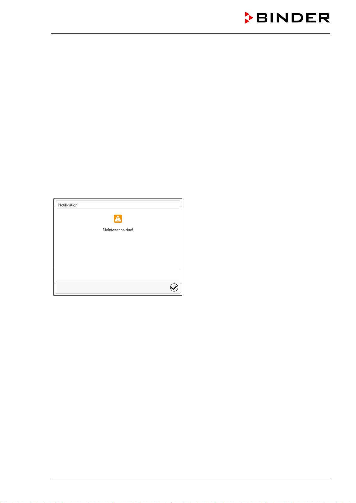
VDL (E3.1) 10/2020 Page 172/196
26.3.2 Maintenance intervals
Ensure regular maintenance work is performed at least once a year and that the legal requirements are
met regarding the qualifications of service personnel, scope of testing and documentation.
Calibration of the Pt 100 controller sensor and, if required, subsequent adjustment shall be performed an-
nually during maintenance. The procedure is described in the Service manual (customer version).
An extended test of the safety temperature limiter (TL) as described in the Service manual shall be per-
formed annually during maintenance.
Maintenance of the pump or vacuum system must be performed regularly as specified by the manufacturer.
When using the VP4 pump provided by BINDER, note the information given by the pump manufacturer.
The technical ventilation (extraction) in the installation area of the chamber must also be monitored in ac-
cordance with relevant standards and regulations (for Germany: TRBS2152 Part 2).
Regular maintenance of the pump must also be carried out.
26.4 Service Reminder
After 8760 operating hours or two years the following message appears:
After confirmation with the Confirm icon, the mes-
sage window will pop up again every two weeks until
it is reset by BINDER Service.
26.4.1 BINDER Service contact data
We recommend taking out a maintenance agreement. Please consult BINDER Service.
BINDER telephone hotline: +49 (0) 7462 2005 555
BINDER fax hotline: +49 (0) 7462 2005 93555
BINDER e-mail hotline: customerservice@binder-world.com
BINDER service hotline USA: +1 866 885 9794 or +1 631 224 4340 x3 (toll-free in the USA)
BINDER service hotline Asia Pacific: +852 390 705 04 or +852 390 705 03
BINDER service hotline Russia and CIS +7 495 988 15 16
BINDER Internet website http://www.binder-world.com
BINDER address BINDER GmbH, post office box 102, D-78502 Tuttlingen
International customers, please contact your local BINDER distributor.
VDL (E3.1) 10/2020 Page 173/196
26.5 Sending the chamber back to BINDER GmbH
If you return a BINDER product to us for repair or any other reason, we will only accept the product upon
presentation of an authorization number (RMA number) that has previously been issued to you. An au-
thorization number will be issued after receiving your complaint either in writing or by telephone prior to
your sending the BINDER product back to us. The authorization number will be issued following receipt of
the information below:
• BINDER product type and serial number
• Date of purchase
• Name and address of the dealer from which you bought the BINDER product
• Exact description of the defect or fault
• Complete address, contact person and availability of that person
• Exact location of the BINDER product in your facility
• A contamination clearance certificate (chap. 32) must be faxed in advance
The authorization number must be applied to the packaging in such a way that it can be easily recognized
or be recorded clearly in the delivery documents.
For security reasons we cannot accept a chamber delivery if it does not carry an authoriza-
tion number.
Return address: BINDER GmbH, Abteilung Service, Gänsäcker 16, 78502 Tuttlingen, Germany
27. Disposal
27.1 Disposal of the transport packing
Packing element
Material
Disposal
Straps to fix packing on pallet
Plastic
Plastic recycling
Wooden transport box (option)
with metal screws
Non-wood (compressed match-
wood, IPPC standard)
Wood recycling
Metal
Metal recycling
Pallet
with foamed plastic stuffing
Solid wood (IPPC standard)
Wood recycling
PE foam
Plastic recycling
Shipping box
with metal clamps
Cardboard
Paper recycling
Metal
Metal recycling
Top cover
Cardboard
Paper recycling
Edge protection
Styropor
®
or PE foam
Plastic recycling
Protection of doors
PE foam
Plastic recycling
Bag for operating manual
PE foil
Plastic recycling
Insulating air cushion foil (packing of
optional accessories)
PE foil Plastic recycling
If recycling is not possible, all packing parts can also be disposed of with normal waste.
27.2 Decommissioning
• Disconnect the oven from the power supply. Disconnect the power plug.
• Turn off the inert gas supply.
VDL (E3.1) 10/2020 Page 174/196
Through the open inert gas connection, inert gas can enter the vacuum drying oven and escape into
the ambient air.
DANGER
Risk of suffocation by inert gas in a high concentration.
Death by suffocation.
Respect the relevant regulations for handling inert gases.
When decommissioning the vacuum drying oven, turn off the inert gas supply.
• Turn off the vacuum pump. Ventilate the chamber as described in chap. 9.9.1.
• Remove the vacuum connection (chap. 6.5).
• Remove the inert gas connection and the pressure reducer (chap. 6.6).
Temporal decommissioning: See indications for appropriate storage, chap. 4.3.
Final decommissioning: Dispose of the chamber as described in chap. 27.3 to 27.5.
27.3 Disposal of the chamber in the Federal Republic of Germany
According to Annex I of Directive 2012/19/EU of the European Parliament and of the Council on waste
electrical and electronic equipment (WEEE), BINDER devices are classified as “monitoring and control
instruments” (category 9) only intended for professional use”. They must not be disposed of at public col-
lecting points.
The chambers bear the symbol for the marking of electrical and electronic equipment manu-
factured / placed on the market in the EC after 13 August 2005 and be disposed of in separate
collection according to Directive 2012/19/EU on waste electrical and electronic equipment
(WEEE) and German national law for electrical and electronic equipment (Elektro- und El-
ektronikgerätegesetz, ElektroG). WEEE marking: crossed-out wheeled bin with solid bar un-
der. A significant part of the materials must be recycled in order to protect the environment.
At the end of the device’s service life, have the chamber disposed of according to the German national law
for electrical and electronic equipment (Elektro- und Elektronikgerätegesetz, ElektroG from 20 October
2015, BGBl. I p. 1739) or contact BINDER service who will organize taking back and disposal of the cham-
ber according to the German national law for electrical and electronic equipment (Elektro- und El-
ektronikgerätegesetz, ElektroG from 20 October 2015, BGBl. I p. 1739).
NOTICE
Danger of violation against existing law if not disposed of properly.
Alteration of the environment.
∅ Do NOT dispose of BINDER devices at public collecting points.
Have the device disposed of professionally at a recycling company which is certified ac-
cording to the German national law for electrical and electronic equipment (Elektro- und
Elektronikgerätegesetz, ElektroG from 20 October 2015, BGBl. I p. 1739).
or
Instruct BINDER Service to dispose of the device. The general terms of payment and
delivery of BINDER GmbH apply, which were valid at the time of purchasing the cham-
ber.
Certified companies disassemble waste (used) BINDER equipment in primary substances for recycling
according to Directive 2012/19/EU. The devices must be free from toxic, infectious or radioactive sub-
stances in order to eliminate any health hazards to the employees of the recycling companies.
VDL (E3.1) 10/2020 Page 175/196
Prior to handing the chamber over to a recycling company, it is the user’s responsibility that it
is free from toxic, infectious or radioactive substances.
• Prior to disposal, clean all introduced or residual toxic substances from the chamber.
• Prior to disposal, disinfect the chamber from all sources of infection. Be aware that sources
of infection may also be located outside the inner chamber.
• If you cannot safely remove all toxic substances and sources of infection from the chamber,
dispose of it as “special” waste according to national law.
• Fill out the contamination clearance certificate (chap. 32) and enclose it with the chamber.
WARNING
Danger of intoxication and infection through contamination of the chamber with
toxic, infectious or radioactive substances.
Damages to health.
∅ NEVER take a chamber contaminated with toxic substances or sources of infection for
recycling according to Directive 2012/19/EU.
Prior to disposal, remove all toxic substances and sources of infection from the cham-
ber.
A chamber from which all toxic substances or sources of infection cannot be safely re-
moved must be considered as “special” waste according to national law. Dispose of it
accordingly.
27.4 Disposal of the chamber in the member states of the EU except for the Fed-
eral Republic of Germany
According to Annex I of Directive 2012/19/EU of the European Parliament and of the Council on waste
electrical and electronic equipment (WEEE), BINDER devices are classified as “monitoring and control
instruments” (category 9) only intended for professional use”. They must not be disposed of at public col-
lecting points.
The chambers bear the symbol for the marking of electrical and electronic equipment manu-
factured / placed on the market in the EC after 13 August 2005 and be disposed of in separate
collection according to the Directive 2012/19/EU on waste electrical and electronic equipment
(WEEE). WEEE marking: crossed-out wheeled bin with solid bar under.
At the end of the device’s service life, notify the distributor who sold you the device, who will
take back and dispose of the chamber according to the Directive 2012/19/EU on waste elec-
trical and electronic equipment (WEEE).
NOTICE
Danger of violation against existing law if not disposed of properly.
Alteration of the environment.
∅ Do NOT dispose of BINDER devices at public collecting points.
Have the device disposed of professionally at a recycling company that is certified ac-
cording to conversion of the Directive 2012/19/EU into national law.
or
Instruct the distributor who sold you the device to dispose of it. The agreements apply
that were agreed with the distributor when purchasing the chamber (e.g. his general
terms of payment and delivery).
If your distributor is not able to take back and dispose of the chamber, please contact
BINDER service.
Certified companies disassemble waste (used) BINDER equipment in primary substances for recycling
according to Directive 2012/19/EU. The devices must be free from toxic, infectious or radioactive sub-
stances in order to eliminate any health hazards to the employees of the recycling companies.
VDL (E3.1) 10/2020 Page 176/196
Prior to handing the chamber over to a recycling company, it is the user’s responsibility that it
is free from toxic, infectious or radioactive substances.
• Prior to disposal, clean all introduced or residual toxic substances from the chamber.
• Prior to disposal, disinfect the chamber from all sources of infection. Be aware that sources
of infection may also be located outside the inner chamber.
• If you cannot safely remove all sources of infection and toxic substances from the chamber,
dispose of it as “special” waste according to national law.
• Fill out the contamination clearance certificate (chap. 32) and enclose it with the chamber.
WARNING
Danger of intoxication and infection through contamination of the chamber with
toxic, infectious or radioactive substances.
Damages to health.
∅ NEVER take a chamber contaminated with toxic substances or sources of infection for
recycling according to Directive 2012/19/EU.
Prior to disposal, remove all toxic substances and sources of infection from the cham-
ber.
A chamber from which all toxic substances or sources of infection cannot be safely re-
moved must be considered as “special” waste according to national law. Dispose of it
accordingly.
27.5 Disposal of the chamber in non-member states of the EU
NOTICE
Danger of violation against existing law if not disposed of properly.
Alteration of the environment.
For final decommissioning and disposal of the vacuum drying oven, please contact
BINDER Service.
Follow the statutory regulations for appropriate, environmentally friendly disposal.
The main board of the vacuum drying oven in the controller housing (triangular instrument box) includes a
lithium cell. Please dispose of it according to national regulations.
28. Technical description
28.1 Factory calibration and adjustment
This chamber was calibrated and adjusted in the factory. Calibration and adjustment were performed using
standardized test instructions, according to the QM DIN EN ISO 9001 system applied by BINDER (certified
since December 1996 by TÜV CERT). All test equipment used is subject to the administration of measure-
ment and test equipment that is also a constituent part of the BINDER QM DIN EN ISO 9001 systems. They
are controlled and calibrated to a DKD-Standard at regular intervals.
Factory adjustment was done in the center of the usable volume and under vacuum conditions. The sensor
is fixed in the middle of the expansion rack in a way ensuring good thermal conductivity (heat conduction).
Measuring is performed in equilibrated state.
VDL (E3.1) 10/2020 Page 177/196
NOTICE
Risk of invalid calibration due to modified heat transmission when changing be-
tween aluminum and stainless-steel racks.
Undefined heating behavior.
∅ Do NOT change between aluminum and stainless-steel racks.
Use the delivered expansion racks only.
28.2 Over current protection
The chambers are protected by one or two miniature fuses against over current, accessible from the out-
side. The miniature fuses are located at the rear of the chamber next to the power cable connection. Each
fuse holder is equipped with a fuse clip 5mm x 20 mm (cUL version 6,3x32 mm). A fuse may be replaced
only with a substitute of the same ratings. Refer to the technical data of the respective device type.
28.3 VDL / VDL-UL technical data
Chamber size
23
56
115
External dimensions
Vacuum drying oven
Width, net
mm / inch
520 / 20.47
637 / 25.10
742 / 29.21
Height, gross (including feet)
mm / inch
720 / 28.35
837 / 32.95
964 / 37.95
Depth, net
mm / inch
490 / 19.29
540 / 21.26
660 / 25.98
Depth, gross (including controller, door handle,
connections, pressure regulator)
mm / inch
632 / 24.88 680 / 26.77 801 / 31.54
Window width
mm / inch
265 / 10.43
380 / 14.96
486 / 19.13
Window height
mm / inch
265 / 10.43
380 / 14.96
486 / 19.13
Pump module (option)
Width, net
mm / inch
523 / 20.59
638 / 25.12
743 / 29.25
Height, net
mm / inch
705 / 27.76
705 / 27.76
705 / 27.76
Depth, net
mm / inch
491 / 19.33
539 / 21.22
659 / 25.94
Depth, gross (including door handle, connec-
tions)
mm / inch
546.5 / 21.52 594.5 / 23.41 714.5 / 28.13
External dimensions
Chamber with optional pump module
Width, net
mm / inch
523 / 20.59
637 / 25.10
742 / 29.21
Height, net
mm / inch
1425 / 56.10
1542 / 60.71
1669 / 65.71
Depth, net
mm / inch
491 / 19.33
540 / 21.26
660 / 25.98
Depth, gross (including controller, door handle,
connections, pressure regulator)
mm / inch
632 / 24.88 680 / 26.77 801 / 31.54
Wall clearances
Wall clearance, rear (minimum)
mm / inch
100 / 3.94
100 / 3.94
100 / 3.94
Wall clearance, side (minimum)
mm / inch
70 / 2.76
70 / 2.76
70 / 2.76
Internal dimensions
Width
mm / inch
285 / 11.22
400 / 15.75
506 / 19.92
Height
mm / inch
285 / 11.22
400 / 15.75
506 / 19.92
Depth
mm / inch
295 / 11.61
343 / 13.50
460 / 18.11
Interior volume
l / cu.ft.
24 / 0.85
55 / 1.94
119 / 4.20

VDL (E3.1) 10/2020 Page 178/196
Chamber size
23
56
115
Racks
Number of expansion racks (aluminum), series
2
2
2
Number of expansion racks (aluminum), max.
4
5
6
Distance between the racks
mm / inch
53 / 2.09
62 / 2.44
68 / 2.68
Usable space per rack (width x depth)
mm / inch
234 x 280
9.21 x 11.02
349 x 320
13.74 x 12.60
455 x 440
17.91 x 17.32
Permissible load per rack
Kg / lbs
20 / 44
20 / 44
20 / 44
Permissible total load
Kg / lbs
50 / 110
60 / 132
70 / 154
Weight
Weight (empty)
Kg / lbs
72 / 159
104 / 229
158 / 348
Temperature data
Temperature range
degrees above room
temperature
°C / °F 9 / 16.2 9 / 16.2 9 / 16.2
up to
°C / °F
110 / 230
110 / 230
110 / 230
Temperature fluctuation at 100 °C / 212 °F
± K
0,1
0,1
0.1
Temperature uniformity (variation)
at 100 °C / 212 °F
± K 1,0 1,5 2,9
Heating up time to 100 °C / 212 °F
Min
150
140
170
Vacuum data
Vacuum connection with small flange
DN mm / inch
16
16
16
Measuring access port with small flange
DN mm / inch
16
16
16
Inert gas connection with flow-limiter
Adapter with hose olive
∅ mm / inch
8 8 8
Vacuum range (adjustable)
mbar / inHg
10 to 1100
10 to 1100
10 to 1100
Leak rate
bar/h
/
inHg
/h
1x10
-2
/ 0.295
1x10
-2
/ 0.295
1x10
-2
/ 0.295
Ex Classification
Ex-Classification of the entire chamber
according to ATEX Directive 2014/34/EU
II 2/3/- G IIB T3 Gb/Gc/- X
Electrical data (model versions VDL023-230V, VDL056-230V, VDL115-230V)
Protection type according to EN 60529 - MB2
controller housing
IP 20 20 20
Protection type, VDL general (type plate)
IP
20
20
20
Nominal voltage
(+/-10%)
at 50 Hz power frequency
V
200-230
200-230
200-230
at 60 Hz power frequency
V
200-230
200-230
200-230
Current type
1N~
1N~
1N~
Nominal power
kW
0,90
1,40
1,60
Nominal current
A
3,9
6,1
7,0
Chamber fuse 5 x 20 mm / 250V / time-lag T
A
2 x 6,3
2 x 8
2 x 10
Power plug
Grounded plug
Over-voltage category acc. to IEC 61010-1
II
II
II
Pollution degree acc. to IEC 61010-1
2
2
2
Different electrical data for VD-UL constructed for the USA and Canada
(model versions VDL023UL-120V, VDL056UL-120V, VDL115UL-120V)
Nominal voltage
(+/-10%)
at 50 Hz power frequency
V
100-120
100-120
100-120
at 60 Hz power frequency
V
100-120
100-120
100-120
Nominal current
A
7,5
11,7
13,4
Chamber fuse 5 x 20 mm / 250V / time-lag T
A
10
2 x 16
--
Chamber fuse 6.3 x 32 mm / 250V / time-lag T
A
--
--
2 x 20
Power plug
NEMA
5-15P
5-20P
5-20P
VDL (E3.1) 10/2020 Page 179/196
Chamber size
23
56
115
Environment-specific data
VDL noise level (mean value)
dB (A)
40
40
40
Energy consumption at 100 °C / 212 °F
Wh/h
140
180
230
All technical data is specified for unloaded chambers with standard equipment (with aluminum racks) at an
ambient temperature of +22 °C +/- 3 °C / 71.6 °F +/- 5.4 °F and a power supply voltage fluctuation of +/- 10
%. Technical data is determined in accordance to BINDER Factory Standard Part 2:2015 and DIN
12880:2007.
All indications are average values, typical for chambers produced in series. We reserve the right to
change technical specifications at any time.
28.4 Equipment and options (extract)
To operate the VDL vacuum drying oven, use only original BINDER accessories or accesso-
ries / components from third-party suppliers authorized by BINDER. The user is responsible
for any risk arising from using unauthorized accessories.
Regular equipment
Microprocessor display program controller MB2 with touch screen
Ethernet interface for computer communication
USB interface
Safety controller (safety device class 2 according to DIN 12880:2007)
Universal connection for inert gas / ambient air “GAS/AIR”, adapter with 8 mm hose olive, with solenoid
valve for inert gas / ambient air
Pressure regulator (rear) for sweeping with compressed air
Analog pressure display (manometer) for sweeping with compressed air
Pressure switch for heating release at 100 mbar
Measuring connection (DN 16), rear
2 vacuum expansion racks
Safety glass panel
Options / accessories
Expansion racks , aluminum or stainless steel 1.4571
Lockable door
Analog outputs 4-20 mA for temperature and pressure
Additional universal connection for inert gas / ambient air „GAS/AIR 2“, adapter with 8 mm hose olive,
with solenoid valve for inert gas / ambient air
Additional universal access port 40 mm
FKM door gasket (temperature resistant up to 150 °C / 302 °F
Object temperature display with flexible Pt 100 temperature sensor
APT-COM™ 4 Multi Management Software for logging and display of temperature data and networking
up to 100 chambers with PC
ATEX connection kit for VP4 vacuum pump with various small flange parts
Pump module
Chemical membrane pump VP4 with separator and emission condenser
•
Ready to connect: Suction power
m
3
/h
1,9
•
End vacuum
mbar
12
•
Electrical connection (50-60 Hz)
V
120 / 230
VDL (E3.1) 10/2020 Page 180/196
Options / accessories
Factory calibration certificate
Extension to factory calibration certificate (additional value)
Calibration certificate of object temperature display
Calibration certificate of pressure display
Extension to factory calibration certificate (additional value) of pressure display
Qualification folder
Evaporating dish, small or large
Stable table on wheels with castors and locking brakes
28.5 Accessories and spare parts (extract)
BINDER GmbH is responsible for the safety features of the chamber only, provided skilled
electricians or qualified personnel authorized by BINDER perform all maintenance and repair,
and if components relating to chamber safety are replaced in the event of failure with original
spare parts. The user is responsible for any risks arising from using unauthorized accesso-
ries/components.
Failure to follow these instructions can result in loss of explosion protection.
Chamber size
23
56
115
Description
Art. no.
Expansion rack, aluminum
8009-1031
8009-1030
8009-1029
Expansion rack, stainless steel
8009-1093
8009-1092
8009-1091
Exchange of aluminum expansion racks for stainless
steel, calibration included
8012-1955 8012-1956 8012-1957
Silicon door gasket, temperature-resistant up to 200 °C /
392°F
6005-0290 6005-0291 6005-0292
FKM door gasket, temperature-resistant up to 150 °C /
302 °F, acid-resistant, silicon free
8012-0502 8012-0501 8012-0500
Chamber fuse 5 x 20 mm / 250V / time lag T for VDL
230 V
5006-0092 5006-0093 5006-0079
Chamber fuse 5 x 20 mm / 250V / time lag T for VDL 23-
UL, VD 56-UL
5006-0079 5006-0103 ---
Chamber fuse 6,3 x 32 mm / 250V / time lag T for VDL
115-UL
--- --- 5006-0030
Safety glass panel
6012-0012
6012-0013
6012-0014
Rack holder
6004-0230
6004-0229
6004-0211
Pump module
8012-1948
8012-1949
8012-1950
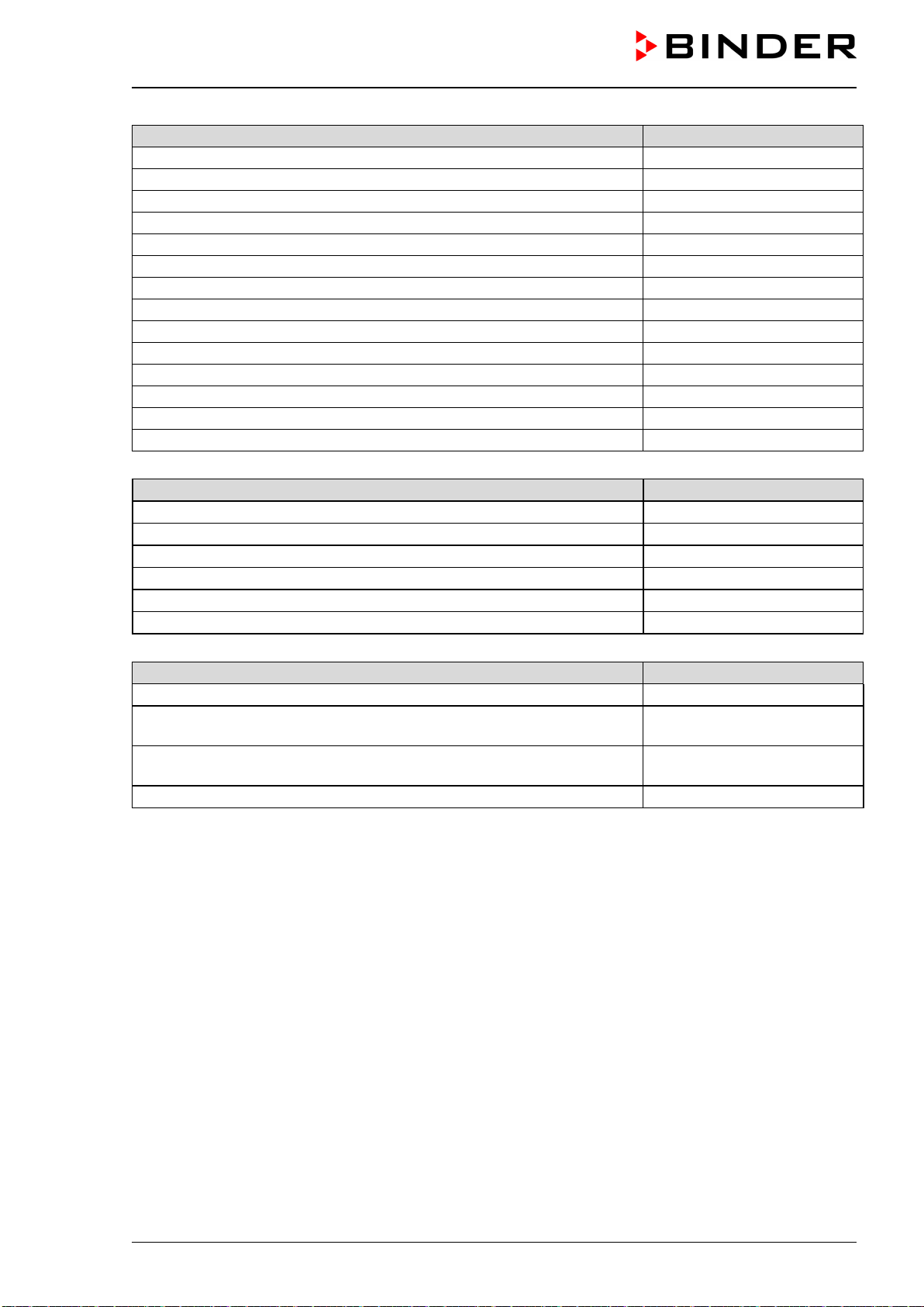
VDL (E3.1) 10/2020 Page 181/196
Description
Art. no.
Accessory kit, consisting of:
8009-0070
Copper seal ring
6005-0056
Hose olive
6009-0064
Universal centering ring
6009-0048
Straining ring
6009-0009
Blind flange
6009-0010
Door handle, complete
6002-0541
Stable table on wheels with castors and locking brakes
9051-0018
Evaporating dish, small
4022-0125
Evaporating dish, large
4022-0126
Vacuum pump VP 4 (230V)
5013-0049
Vacuum pump VP 4 (120V)
5013-0118
Connection kit for vacuum pump VP4
8012-0621
Neutral cleaning agent, 1 kg
1002-0016
Validation service
Art. No.
Qualification folder IQ-OQ (printed version)
7007-0001
Qualification folder IQ-OQ (digital version)
7057-0001
Qualification folder IQ-OQ-PQ (printed version)
7007-0005
Qualification folder IQ-OQ-PQ (digital version)
7057-0005
Execution of IQ-OQ
DL420300
Execution of IQ-OQ-PQ
DL440500
Calibration service
Art. no.
Calibration of temperature including certificate (1 measuring point)
8012-1145
Spatial temperature measurement including certificate (9 measuring
points)
8012-0916
Spatial temperature measurement including certificate (15 measuring
points)
8012-0919
Calibration of pressure including certificate
8012-0440
For information on components not listed here, please contact BINDER Service.
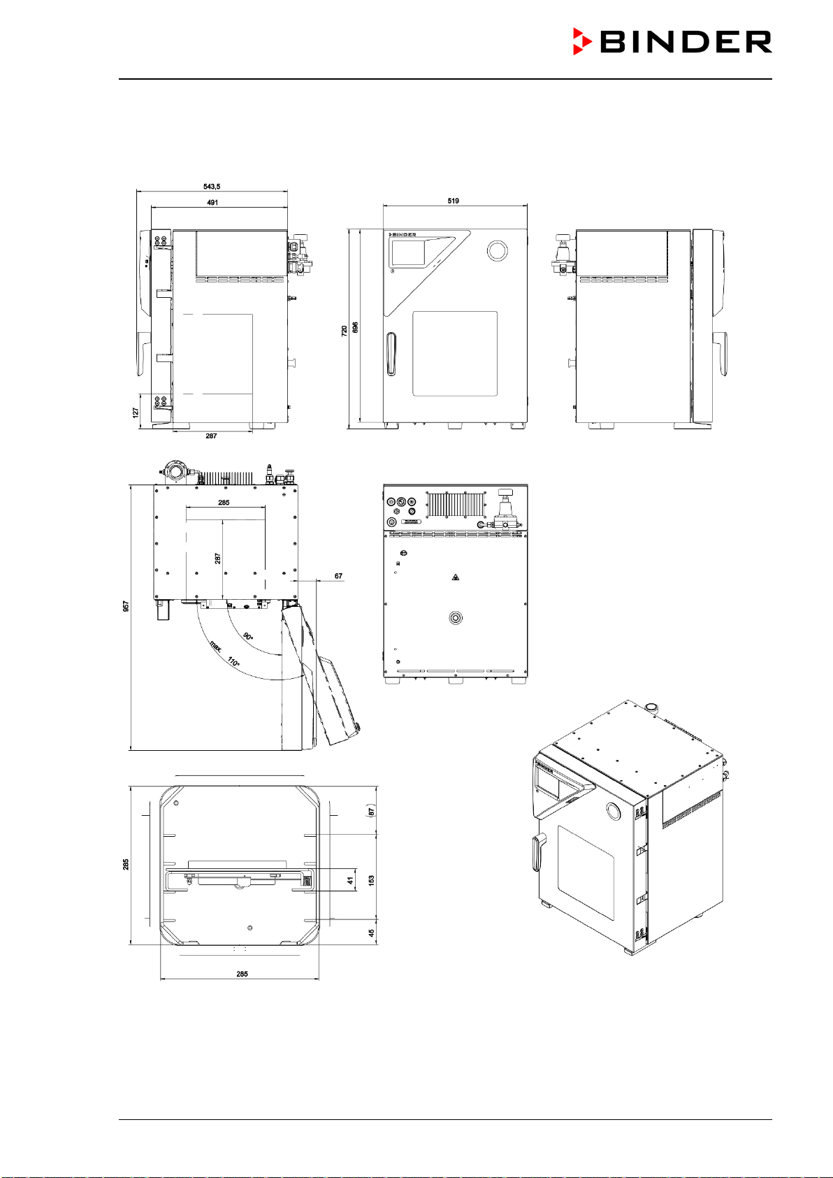
VDL (E3.1) 10/2020 Page 182/196
28.6 Dimensions
28.6.1 VDL 23
(Dimensions in mm)
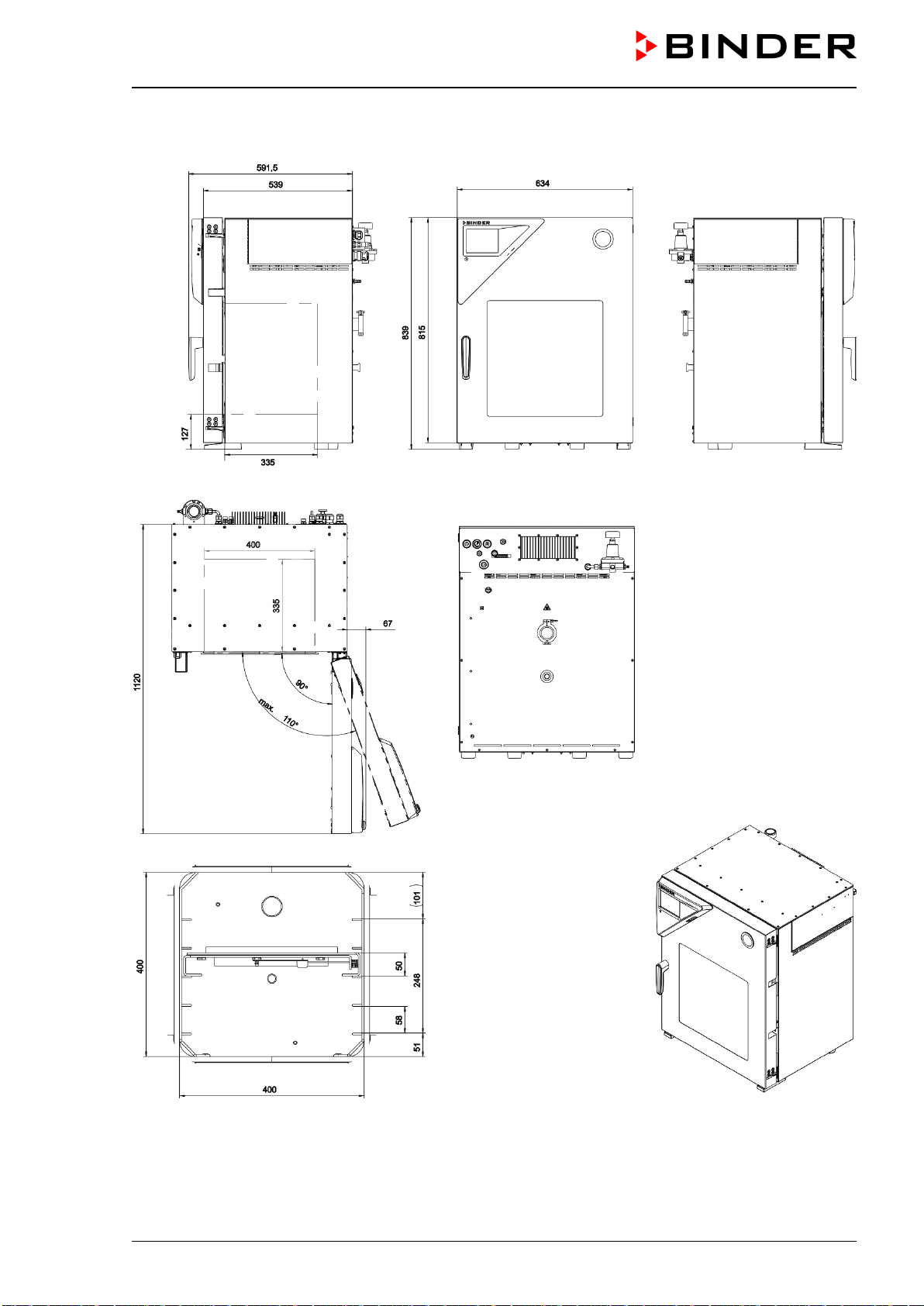
VDL (E3.1) 10/2020 Page 183/196
28.6.2 VDL 56
(Dimensions in mm)
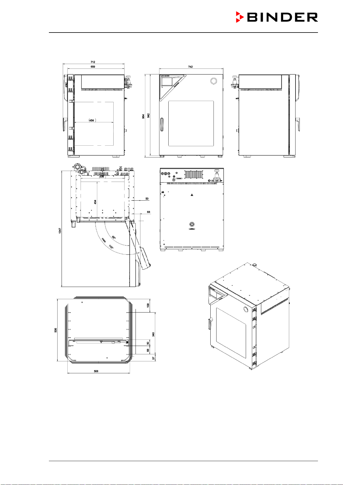
VDL (E3.1) 10/2020 Page 184/196
28.6.3 VDL 115
(Dimensions in mm)

VDL (E3.1) 10/2020 Page 185/196
29. Index
Activation code 113
Ambient temperature 52
Analog output 161
Analog outputs 44
Area classification 25, 44, 47
Audible alarm 126
Auto-ignition temperature 18, 19, 22, 25, 26, 33,
34, 35, 37, 38, 60, 62, 63, 84, 85, 91, 92, 95,
96, 97, 129, 131, 143
Cleaning 163
Commissioning 70, 71
Compressed air supply 16, 21, 27, 30, 44, 52, 54,
56, 84, 85, 86, 160
Compressed air sweeping 16, 21, 22, 24, 25, 27,
44, 46, 56, 84, 85, 86, 87, 88, 160
Condensate catchpot 18, 27, 39, 51, 85, 96
Connection kit 59, 64, 179, 181
Corrosion 53, 61, 63
Domestic vacuum system 59
Drying monitoring 103
Drying monitoring 85
Dust 15, 19, 26, 50, 92
Emergency ventilation 44, 48, 82, 93, 94
Equipotential bonding 26, 38, 40, 52, 66, 67, 91
Equipotential bonding 84
ESD 20, 27, 28, 32, 33, 39, 52, 66, 68, 85, 91,
95, 96
Ethernet 36, 44, 161, 179
Ex classification 13, 36
Exothermal reactions 26
Expansion rack 180
Expansion racks 37, 53, 54, 164, 166, 178, 179
Explosion group 19, 26
Explosion hazard 8, 15, 16, 17, 18, 19, 21, 50,
51, 53, 57, 58, 60, 61, 62, 63, 69, 92, 94, 95,
97, 129, 131, 143, 161
Explosion protection document 32, 70, 71
Explosion protection plan 14, 32, 33, 70, 71
Explosion protection symbol 10, 13
Extraction 18, 27, 39, 50, 51, 91, 95, 96, 172
Fire extinguisher 52
Flame arrester 64
Foreseeable misuse 34
Foreseeable Misuse 28
Fuse 177
Gas group 19, 26
Gas inlet temperature 18, 60, 62, 63
GAS/AIR 44, 93, 100, 179
Gloves 28, 33, 39, 72, 91, 96
Grounding concept 15, 66, 84
Grounding plan 26, 38, 40, 91
Heater release 38
Heating release 179
Ignition source monitoring 37, 120
Inert gas
21, 22, 62, 63, 64, 93, 100, 174
Inert gas connection 64
Instrument box 42, 155
Intended use 25
interface 179
Interface 36, 42, 44, 161, 163
Labels 12
Lightning protection device 52
Loading area 20, 39, 51, 52, 92
Maintenance 35, 171, 172
Manual ventilation 44, 48, 93, 94
Measuring connection 42, 162, 179
Medical devices 26
Object temperature display 44, 162, 163
Object temperature input 162
Operating instructions 28, 29, 33, 34
Overheating 15
Password protection 91, 105
Personal protective equipment 28, 32, 33, 52, 66,
68, 91, 95, 96
Personal protective equipment 20
Plug 44, 48, 93, 94
PPE 20, 27, 33, 52, 66, 68, 72, 91, 95, 96
Pressure threshold 85

VDL (E3.1) 10/2020 Page 186/196
Pump module 21, 38, 39, 47, 48, 50, 52, 57, 59,
61, 62, 63, 66, 67, 70, 177, 179, 180
Rack holder 180
Rack holders 53
Residual risks 30, 34
Risk assessment 32
safety alert symbol 10
Safety controller 22, 35, 40, 83, 84, 96, 119, 121,
168, 179
Safety glass panel 40, 180
Safety glass window 41
Safety pressure monitoring 38
Safety temperature 91
SOP 34
Stacking 50
Standard Operating Procedures 34
Standby 84, 89, 91, 99, 140
Technical ventilation 16, 18, 21, 22, 27, 39, 46,
49, 50, 51, 59, 72, 73, 83, 84, 88, 89, 91, 95,
96, 172
Temperature class 13, 18, 19, 25, 36, 60, 62, 63
Termination of the drying process 34, 94
Tests 71, 73
tolerance range 83
Tolerance range 122
Transport 49
TRGS 725 72, 73
Type plate 13, 25, 28, 36, 40, 68
Unpacking 48
USB 36, 42, 155, 179
Vacuum connection 44, 59
Vacuum pump 17, 47, 50, 52, 59, 60, 61, 62, 63,
64, 66, 70, 181
Vacuum supply 17
Zone 15, 17, 21, 25, 27, 28, 44, 50, 59, 62, 63,
64
Zone classification 44
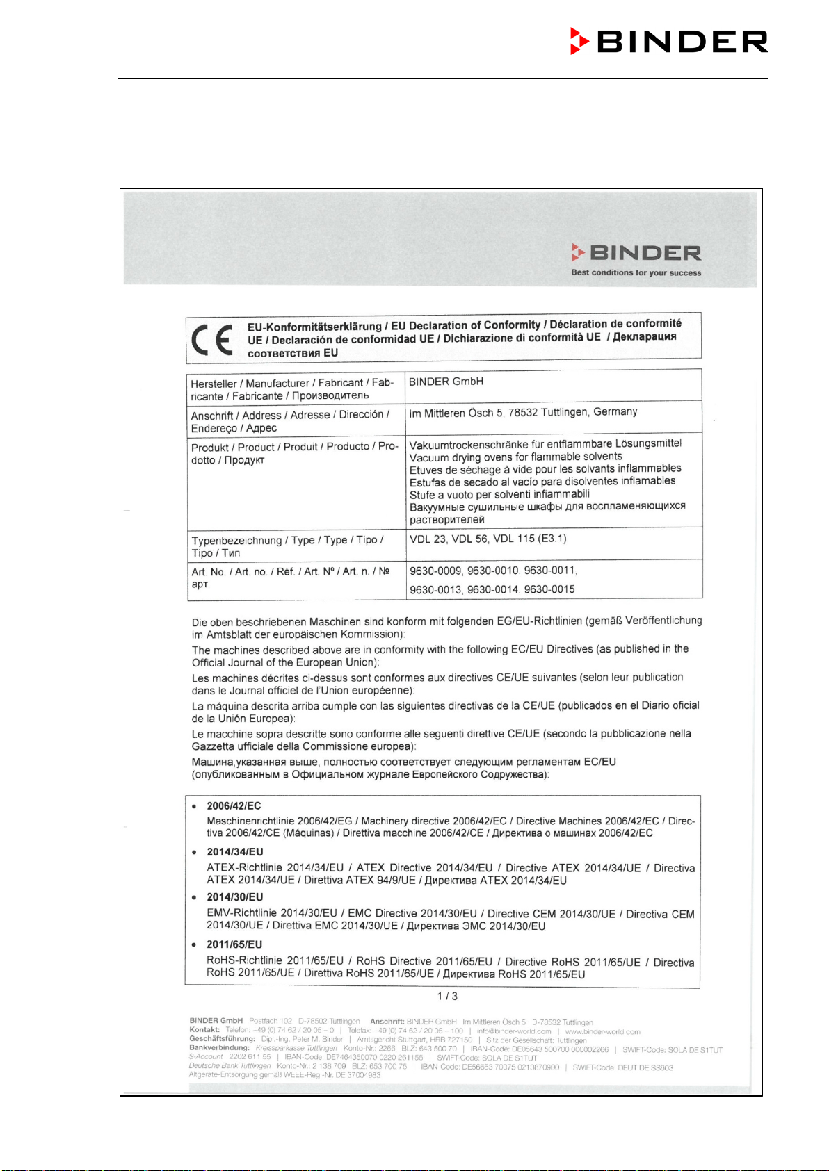
VDL (E3.1) 10/2020 Page 187/196
30. Certificates and declarations of conformity
30.1 EU Declaration of Conformity
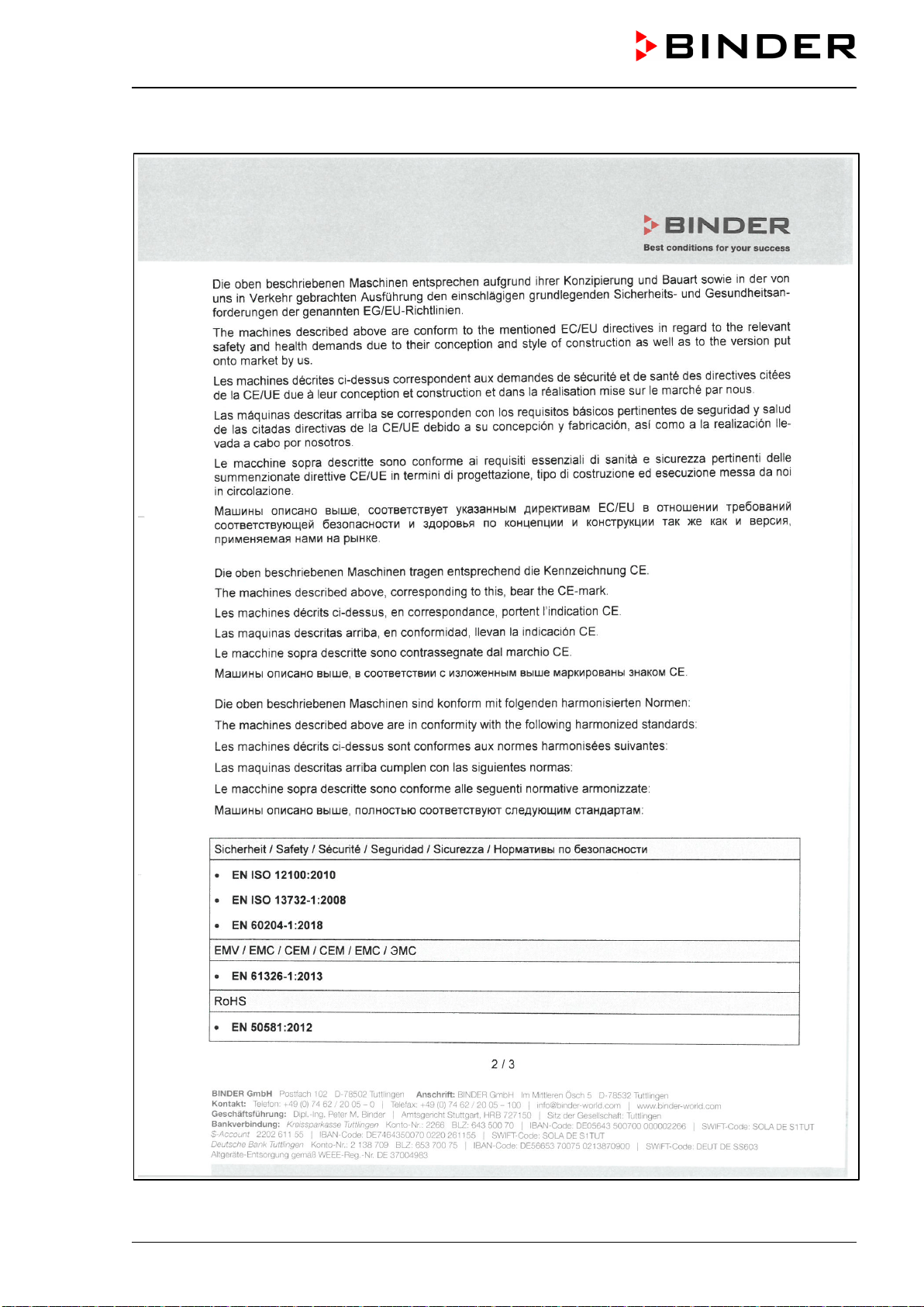
VDL (E3.1) 10/2020 Page 188/196
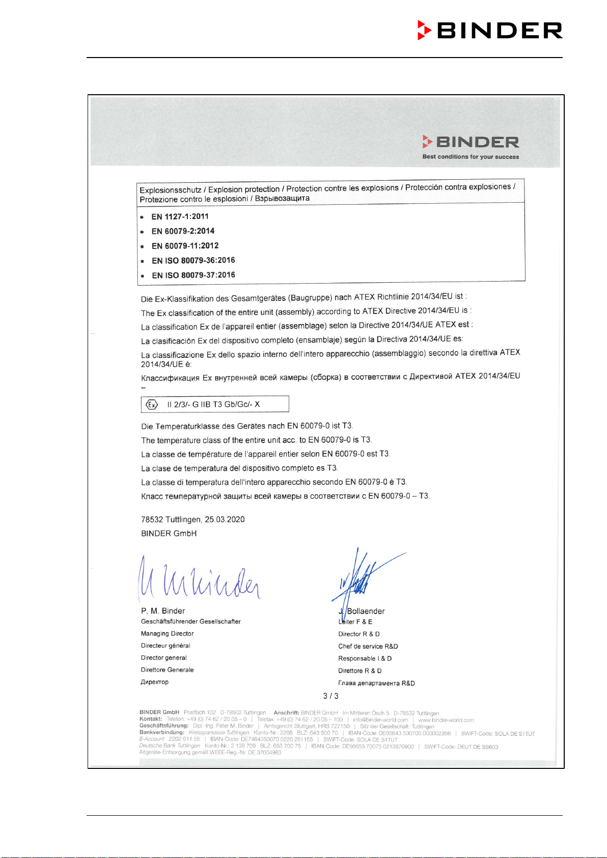
VDL (E3.1) 10/2020 Page 189/196
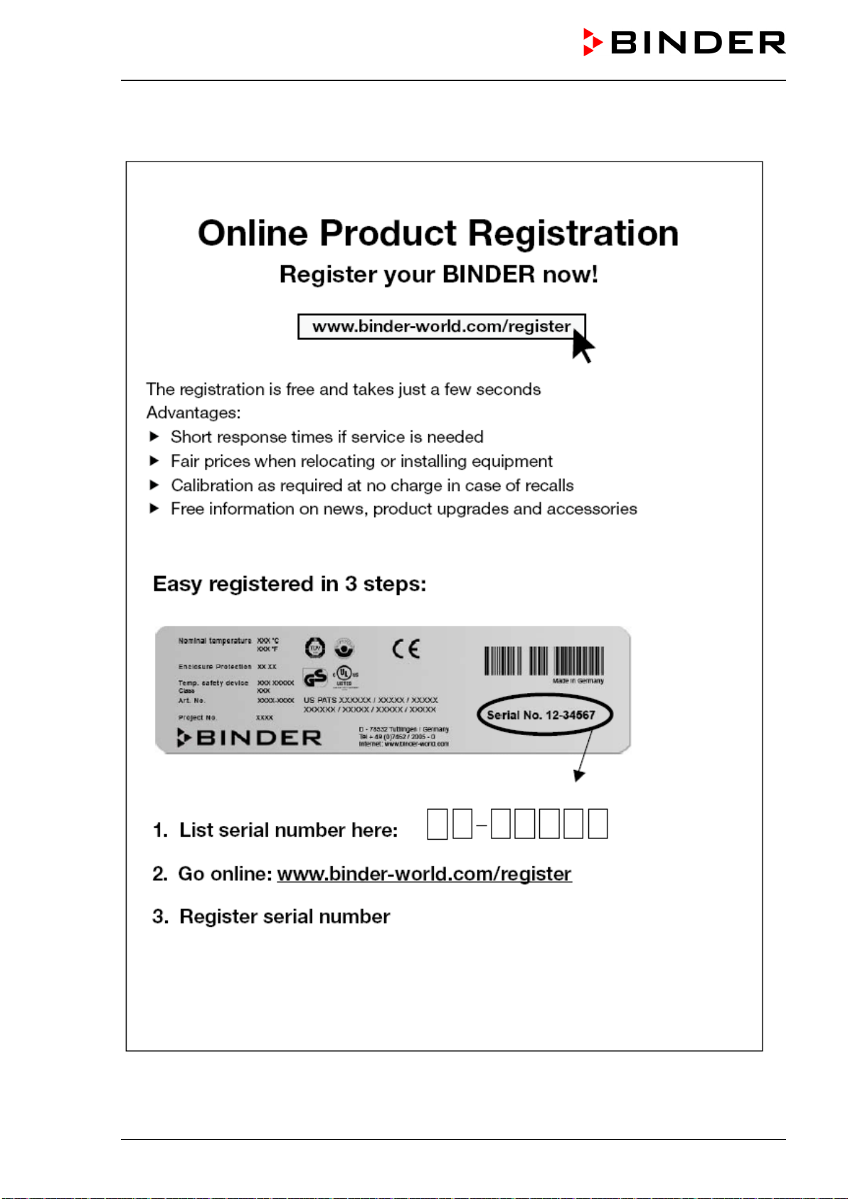
VDL (E3.1) 10/2020 Page 190/196
31. Product registration
VDL (E3.1) 10/2020 Page 191/196
32. Contamination clearance certificate
32.1 For chambers located outside USA and Canada
Declaration regarding safety and health
Erklärung zur Sicherheit und gesundheitlichen Unbedenklichkeit
The German Ordinance on Hazardous Substances (GefStofV), and the regulations regarding safety at the
workplace, require that this form be filled out for all products that are returned to us, so that the safety and
the health of our employees can be guaranteed.
Die Sicherheit und Gesundheit unserer Mitarbeiter, die Gefahrstoffverordnung GefStofV und die Vorschriften zur Si-
cherheit am Arbeitsplatz machen es erforderlich, dass dieses Formblatt für alle Produkte, die an uns zurückgeschickt
wird.
Note: A repair is not possible without a completely filled out form.
Ohne Vorliegen des vollständig ausgefüllten Formblattes ist eine Reparatur nicht möglich.
• A completely filled out form must be transmitted via Fax (+49 (0) 7462 2005 93555) or by letter in
advance, so that this information is available before the equipment/component part arrives. A second
copy of this form must accompany the equipment/component part. In addition, the carrier should be
notified.
Eine vollständig ausgefüllte Kopie dieses Formblattes soll per Telefax (Nr. +49 (0) 7462 2005 93555) oder Brief
vorab an uns gesandt werden, so dass die Information vorliegt, bevor das Gerät/Bauteil eintrifft. Eine weitere Kopie
soll dem Gerät/Bauteil beigefügt sein. Ggf. ist auch die Spedition zu informieren.
• Incomplete information or non-conformity with this procedure will inevitably lead to substantial delays in
processing. Please understand the reason for this measure, which lies outside our area of influence,
and will help us to speed up this procedure.
Unvollständige Angaben oder Nichteinhalten dieses Ablaufs führen zwangsläufig zu beträchtlichen Verzögerungen
in der Abwicklung. Bitte haben Sie Verständnis für Maßnahmen, die außerhalb unserer Einflussmöglichkeiten liegen
und helfen Sie mit, den Ablauf beschleunigen.
• Please print and fill out this form completely.
Bitte unbedingt vollständig ausfüllen!
1. Unit/ component part / type: /
Gerät / Bauteil / Typ:
2. Serial No. /
Serien-Nr.:
3. Details about utilized substances / biological substances /
Einzelheiten über die eingesetzten
Substanzen/biologische Materialien:
3.1 Designations /
Bezeichnungen:
a) ____________________________________________________________________________
b) ____________________________________________________________________________
c) ____________________________________________________________________________
3.2 Safety measures required for handling these substances /
Vorsichtsmaßnahmen beim Umgang
mit diesen Stoffen:
a) ____________________________________________________________________________
b) ____________________________________________________________________________
c) ____________________________________________________________________________
VDL (E3.1) 10/2020 Page 192/196
3.3 Measures to be taken in case of skin contact or release into the atmosphere /
Maßnahmen
bei Personenkontakt oder Freisetzung:
a) ____________________________________________________________________________
b) ____________________________________________________________________________
c) ____________________________________________________________________________
d) ____________________________________________________________________________
3.4 Other important information that must be taken into account /
Weitere zu beachtende und
wichtige Informationen:
a) ____________________________________________________________________________
b) ____________________________________________________________________________
c) ____________________________________________________________________________
4. Declaration on the risk of these substances (please checkmark the applicable items) /
Erklärung zur Gefährlichkeit der Stoffe (bitte Zutreffendes ankreuzen) :
4.1 For non toxic, non radioactive, biologically harmless materials /
für nicht giftige, nicht radioak-
tive, biologisch ungefährliche Stoffe:
We hereby guarantee that the above-mentioned unit / component part… / Wir versichern, dass o.g.
Gerät/Bauteil...
Has not been exposed to or contains any toxic or otherwise hazardous substances /
weder giftige noch
sonstige gefährliche Stoffe enthält oder solche anhaften.
That eventually generated reaction products are non-toxic and also do not represent a hazard / auch
evtl. entstandene Reaktionsprodukte weder giftig sind noch sonst eine Gefährdung darstellen.
Eventual residues of hazardous substances have been removed /
evtl. Rückstände von Gefahrstoffen ent-
fernt wurden.
4.2 For toxic, radioactive, biologically harmful or hazardous substances, or any other ha-
zardous materials / für giftige, radioaktive, biologisch bedenkliche bzw. gefährliche Stoffe oder ander-
weitig gefährliche Stoffe.
We hereby guarantee that … / Wir versichern, dass …
The hazardous substances, which have come into contact with the above-mentioned equipment/com-
ponent part, have been completely listed under item 3.1 and that all information in this regard is com-
plete /
die gefährlichen Stoffe, die mit dem o.g. Gerät/Bauteil in Kontakt kamen, in 3.1 aufgelistet sind und alle
Angaben vollständig sind.
That the unit /component part has not been in contact with radioactivity / das Gerät/Bauteil nicht mit Radi-
oaktivität in Berührung kam
5. Kind of transport / transporter /
Transportweg/Spediteur:
Transport by (means and name of transport company, etc.)
Versendung durch (Name Spediteur o.ä.)
__________________________________________________________________________________
Date of dispatch to BINDER GmbH /
Tag der Absendung an BINDER GmbH:
__________________________________________________________________________________
VDL (E3.1) 10/2020 Page 193/196
We hereby declare that the following measures have been taken /
Wir erklären, dass folgende Maßnahmen
getroffen wurden:
Hazardous substances were removed from the unit including component parts, so that no hazard exists
for any person in the handling or repair of these items /
das Gerät/Bauteil wurde von Gefahrstoffen befreit,
so dass bei Handhabung/Reparaturen für die betreffenden Person keinerlei Gefährdung besteht
The unit was securely packaged and properly identified /
das Gerät wurde sicher verpackt und vollständig
gekennzeichnet.
Information about the hazardousness of the shipment (if required) has been provided to the transporter
/
der Spediteur wurde (falls vorgeschrieben) über die Gefährlichkeit der Sendung informiert.
We hereby commit ourselves and guarantee that we will indemnify BINDER GmbH for all damages that
are a consequence of incomplete or incorrect information provided by us, and that we will exempt
BINDER GmbH from eventual damage claims by third parties./
Wir versichern, dass wir gegenüber BINDER
für jeden Schaden, der durch unvollständige und unrichtige Angaben entsteht, haften und BINDER gegen eventuell
entstehende Schadenansprüche Dritter freistellen.
We are aware that, in accordance with Article 823 of the German Civil Code (BGB), we are directly liable
with regard to third parties, in this instance especially the employees of BINDER GmbH, who have been
entrusted with the handling / repair of the unit / component. /
Es ist uns bekannt, dass wir gegenüber Dritten –
hier insbesondere mit der Handhabung/Reparatur des Geräts/des Bauteils betraute Mitarbeiter der Firma BINDER -
gemäß §823 BGB direkt haften
Name: _______________________________________________________________________
Position/Title: _______________________________________________________________________
Date /
Datum: _______________________________________________________________________
Signature /
Unterschrift: _______________________________________________________________
Company stamp /
Firmenstempel:
Equipment that is returned to the factory for repair must be accompanied by a completely
filled out contamination clearance certificate. For service and maintenance on site, such a
contamination clearance certificate must be submitted to the service technician before the
start of any work. No repair or maintenance of the equipment is possible, without a properly
filled out contamination clearance certificate.
VDL (E3.1) 10/2020 Page 194/196
32.2 For chambers located in USA and Canada
Product Return Authorization Request
Please complete this form and the Customer Decontamination Declaration (next 2 pages) and attach the
required pictures. E-mail to: IDL_SalesOrderProcessing_USA@binder-world.com
After we have received and reviewed the complete information we will decide on the issue of a RMA num-
ber. Please be aware that size specifications, voltage specifications as well as performance specifications
are available on the internet at www.binder-world.us
at any time.
Take notice of shipping laws and regulations.
Please fill:
Reason for return request Duplicate order
Duplicate shipment
Demo Page one completed by sales
Power Plug / Voltage 115V / 230 V / 208 V / 240V
Size does not fit space
Transport Damage Shock watch tripped? (pictures)
Other (specify below)
_____________________
Is there a replacement PO? Yes No
If yes -> PO #
If yes -> Date PO placed
Purchase order number
BINDER model number
BINDER serial number
Date unit was received
Was the unit unboxed? Yes No
Was the unit plugged in? Yes No
Was the unit in operation? Yes No
Pictures of unit attached?
Pictures of Packaging at-
tached?
Yes No
Yes No
Pictures have to be attached!
Customer Contact Information Distributor Contact Information
Name
Company
Address
Phone
E-mail
VDL (E3.1) 10/2020 Page 195/196
Customer (End User) Decontamination Declaration
Health and Hazard Safety declaration
To protect the health of our employees and the safety at the workplace, we require that this form is com-
pleted by the user for all products and parts that are returned to us. (Distributors or Service Organizations
cannot sign this form)
NO RMA number will be issued without a completed form. Products or parts returned to our
NY warehouse without a RMA number will be refused at the dock.
A second copy of the completed form must be attached to the outside of the shipping box.
1. Unit/ component part / type
:
2. Serial No.
3. List any exposure to hazardous liquids, gasses or substances and radioactive material
3.1 List with MSDS sheets attached where available or needed
(if there is not enough space available below, please attach a page):
a) ____________________________________________________________________________
b) ____________________________________________________________________________
c) ____________________________________________________________________________
3.2 Safety measures required for handling the list under 3.1
a) ____________________________________________________________________________
b) ____________________________________________________________________________
c) ____________________________________________________________________________
3.3 Measures to be taken in case of skin contact or release into the atmosphere
:
a) ____________________________________________________________________________
b) ____________________________________________________________________________
c) ____________________________________________________________________________
d) ____________________________________________________________________________
3.4 Other important information that must be considered
:
a) ____________________________________________________________________________
b) ____________________________________________________________________________
c) ____________________________________________________________________________
VDL (E3.1) 10/2020 Page 196/196
4. Declaration of Decontamination
For toxic, radioactive, biologically and chemically harmful or hazardous substances, or any other
hazardous materials.
We hereby guarantee that
4.1 Any hazardous substances, which have come into contact with the above-mentioned equipment /
component part, have been completely listed under item 3.1 and that all information in this regard is
complete
.
4.2 That the unit /component part has not been in contact with radioactivity
4.3 Any Hazardous substances were removed from the unit / component part, so that no hazard exists
for a persons in the shipping, handling or repair of these returned unit
4.4 The unit was securely packaged in the original undamaged packaging and properly identified on the
outside of the packaging material with the unit designation, the RMA number and a copy of this dec-
laration.
4.5 Shipping laws and regulations have not been violated.
I hereby commit and guarantee that we will indemnify BINDER Inc. for all damages that are a con-
sequence of incomplete or incorrect information provided by us, and that we will indemnify and
hold harmless BINDER Inc. from eventual damage claims by third parties.
Name: _______________________________________________________________________
Position: _______________________________________________________________________
Company: _______________________________________________________________________
Address: _______________________________________________________________________
Phone #: _______________________________________________________________________
Email: _______________________________________________________________________
Date: _______________________________________________________________________
Signature: _______________________________________________________________________
Equipment returned to the NY warehouse for repair must be accompanied by a completed
customer decontamination declaration. For service and maintenance works on site, such a
customer decontamination declaration must be submitted to the service technician before the
start of work. No repair or maintenance of the equipment is possible without a completed
form.