
Cybex - V Series Treadmill
Assembly Instructions
Part Number
1008693-0001 AA


User and Service Documents Link
Operation Manuals and other Product Information available at
https://www.lftechsupport.com/web/document-library/documents
https://www.lftechsupport.com/web/document-library/documents
https://www.lftechsupport.com/web/document-library/documents
https://www.lftechsupport.com/web/document-library/documents
https://www.lftechsupport.com/web/document-library/documents
https://www.lftechsupport.com/web/document-library/documents
Trobareu el manual de funcionament i altra informació de producte a
https://www.lftechsupport.com/web/document-library/documents
Mae Llawlyfrau Gweithredu a Gwybodaeth Arall am Beiriannau ar gael yn
https://www.lftechsupport.com/web/document-library/documents
Die Betriebsanleitung und andere Produktinformationen erhalten Sie unter
https://www.lftechsupport.com/web/document-library/documents
Encontrará el manual de funcionamiento y otra información de producto en
https://www.lftechsupport.com/web/document-library/documents
Erabiltzailearen Eskuliburua eta Beste Produktuei buruzko Informazioa eskuratu
https://www.lftechsupport.com/web/document-library/documents gunean
Käyttöoppaat ja muut tuotetiedot ovat saatavana osoitteessa
https://www.lftechsupport.com/web/document-library/documents
Les manuels d’utilisation, ainsi que d’autres informations sur les Produits, sont disponibles sur
https://www.lftechsupport.com/web/document-library/documents
Felhasználói kézikönyvek és más termékinformációk:
https://www.lftechsupport.com/web/document-library/documents
Manuali di funzionamento e altre informazioni sui prodotti disponibili su
https://www.lftechsupport.com/web/document-library/documents
Instrukcje obsługi i inne informacje o produktach dostępne na stronie
https://www.lftechsupport.com/web/document-library/documents
Manuais de Operação e Informações sobre outros produtos disponíveis em
https://www.lftechsupport.com/web/document-library/documents
https://www.lftechsupport.com/web/document-library/documents
Kullanım Kılavuzları ve Diğer Ürün Bilgileri https://www.lftechsupport.com/web/document-library/documents’da
bulunmaktadır
Page 3 of 31

Table of Contents
Getting Started
Safety Instructions........................................................................................................................5
Consignés de Sécurité..................................................................................................................7
Set-Up..............................................................................................................................................9
Product Overview
Product Features........................................................................................................................13
Mounting and Dismounting the Treadmill............................................................................13
User Position................................................................................................................................13
Using and Testing the Emergency Stop System...................................................................14
Assembly
Component and Hardware List...............................................................................................15
Tools Required............................................................................................................................16
Remove Motor Cover..................................................................................................................16
Install Uprights............................................................................................................................17
Install Front Crossbar.................................................................................................................18
Install Bridge................................................................................................................................18
Tighten Upper Hardware...........................................................................................................20
Tighten Lower Hardware...........................................................................................................20
Install Plastic Grommets...........................................................................................................20
Install Upper Dashboard Tray..................................................................................................21
Install Console.............................................................................................................................22
Console Connections.................................................................................................................22
Install Lower Dashboard Tray..................................................................................................23
Install Rear End Caps.................................................................................................................23
Install Motor Cover.....................................................................................................................23
Install Front End Caps................................................................................................................24
Service and Technical Data
Preventive Maintenance Tips...................................................................................................25
Approved and Compatible Cleaners.......................................................................................25
Preventive Maintenance Schedule..........................................................................................26
Troubleshooting the Treadmill................................................................................................26
How to Adjust and Tension the Striding Belt........................................................................28
The Belt Tensioning Bolts.........................................................................................................28
Tracking (Centering) A Striding Belt........................................................................................28
Tensioning an Existing Striding Belt.......................................................................................29
How To Obtain Product Service..............................................................................................29
Specifications
V Series Treadmill - Specifications..........................................................................................30
Cybex
®
and the Cybex logo are registered trademarks of Cybex International, Inc.
DISCLAIMER: CybexInternational, Inc. makes no representations or warranties regarding the contents of this manual. We reserve the right to revise this document
at any time or to make changes to the product described within it without notice or obligation to notify any person of such revisions or changes.
©
Copyright 2018, Cybex International, Inc.
Columbia Center III - 9525 West Bryn Mawr Ave, Rosemont, IL 60018 • 800-351-3737 • 847-288-3700 • FAX 800-216-8893
www.cybexintl.com • 1008693-0001 AA • 2018
Page 4 of 31

Getting Started
Safety Instructions
Read all instructions before use.
Warning: Health-related injuries may result from incorrect or excessive use of exercise equipment. Cybex
International, Inc. STRONGLY recommends seeing a physician for a complete medical exam before undertaking
an exercise program, particularly if the user has a family history of high blood pressure or heart disease, is
over the age of 45, smokes, has high cholesterol, is obese, or has not exercised regularly in the past year. If,
at any time while exercising, the user experiences faintness, dizziness, pain, or shortness of breath, he or she
must stop immediately.
Caution: Any changes or modifications to this equipment could void the product warranty.
Danger: To reduce the risk of electrical shock or injury from moving parts, always unplug product before
cleaning or attempting any maintenance activity.
Warning: To reduce the risk of burns, fire, electric shock, or injury, it is imperative to connect each product
to a properly grounded electrical outlet.
Warning: Heart rate monitoring systems may be inaccurate. Over exercising may result in serious injury or
death. If you feel faint, stop exercising immediately.
Warning: Keep the area 6.5 ft. (2 m) by 3 ft. (0.9 m) behind the treadmill clear of any obstructions, including
walls, furniture, and other equipment. Contact Customer Support Services for an optional longer power cord
if necessary.
Warning: Be sure the emergency stop lanyard is clipped to the user and in proper position on the treadmill
before beginning any workout.
Warning: The belt centering adjustment must be performed if the belt is not between the marks indicating
the maximum allowed lateral positions. Refer to Treadmill Assembly Instructions.
Caution: Risk of injury to persons – to avoid injury, use extreme caution when stepping onto or off of a
moving belt. Read assembly instruction manual before using.
• Never operate the product if it has a damaged power cord or electrical plug, or if it has been dropped, damaged,
or even partially immersed in water. Contact Customer Support Services.
• Position the product so that the power cord plug to the wall is accessible to the user. Make sure that the power
cord is not knotted or twisted and that it is not trapped under any equipment or other objects.
• If the electrical supply cord is damaged, it must be replaced by the manufacturer, an authorized service agent,
or a similarly qualified person to avoid a hazard.
• Always follow the console instructions for proper operation.
• This appliance is not intended for useby persons (including children) with reduced physical, sensory, or mental
capabilities, or lack of experience or knowledge unless they have supervision or been given instruction concerning
the use of the appliance by a person responsible for their safety.
• Do not use this product outdoors, near swimming pools or in areas of high humidity.
• Never operate the product with the air openings blocked. Keep air openings free of lint, hair, or any other
obstructing material.
• Never insert objects into any opening in these products. If an object should drop inside, turn off the power,
unplug the power cord from the outlet, and carefully retrieve it. If the item cannotbe reached, contact Customer
Support Services.
• Never place liquids of any type directly on the unit, except in an accessory tray or holder. Containers with lids
are recommended.
Page 5 of 31

• Do not use these products in bare feet. Always wear shoes. Wear shoes with rubber or high-traction soles. Do
not use shoes with heels, leather soles, cleats or spikes. Make sure no stones are embedded in the soles.
• Keep all loose clothing, shoelaces, and towels away from moving parts.
• Do not reach into, or underneath, the unit or tip it on its side during operation.
• This equipment is not intended for use by children. Keep children under the age of 14 away from the machine.
• Do not allow other people to interfere in any way with the user or equipment during a workout.
• Allow LCD consoles to “normalize” with respect to temperature for one hour before plugging the unit in and
using.
• The product should never be left unattended when plugged in. Disconnect from the electrical outlet when not
in use, and before putting on or taking off parts. To disconnect, turn power OFF at the ON/OFF switch, then
remove plug from electrical outlet.
• Keep the power cord away from heated surfaces. Do not pull the equipment by the power cord or use the cord
as a handle. Do not run the power cord on the floor under or along the side of the treadmill.
• Handrails may be held to enhance stability as needed, but are not for continuous use.
• Never mount or dismount the treadmill while the running belt is moving. Use the handrails whenever additional
stability is required. In case of an emergency, such as tripping, grasp the handrails, and place the feet on the
side platforms.
• Never walk or jog backwards on the treadmill.
• Do not use this product in areas where aerosol spray products are being used or where oxygen is being
administered. Such substances create the danger of combustion and explosion.
• The system causes immobilization of the treadmill when a pre-defined hard key sequence has been activated.
This sequence is currently defined as 3 STOP key presses followed by 3 SPEED DOWN ARROW key presses. To
prevent false toggling of the Immobilized feature, this sequence must be done in a 5-10 second period.
• Use these products for their intended use as described in this manual. Do not use attachments that have not
been recommended by the manufacturer.
• In conformity with the European Union Machinery Directive 2006/42/EC, this equipment unloaded runs at sound
pressure levels below 70 dB (A) at the average operating speed of 12 km/hr (commercial units) and 8 km/hr
(home units). Noise emission under load is higher than without load.
• Free standing equipment shall be installed on a stable and leveled surface.
• Read all warnings on each product prior to starting a workout.
• If warnings are missing or damaged, please contact Customer Support Services immediately for replacement
warning labels. Warning labels are shipped with every product and should be installed before product is used.
Cybex International, Inc. is not responsible for missing or damaged warning labels.
• Health and Environmental Regulations Warning - This product may contain chemicals known to the State of
California to cause cancer, birth defects, or other reproductive harm. For more information related to the
European Commission Regulation (EC) No. 1907/2006 (REACH) and the California Safe Drinking Water and Toxic
Enforcement Act of 1986 (Proposition 65), please visit
https://www.lftechsupport.com/web/guest/environmental-regulations-information.
Page 6 of 31

Consignés de Sécurité
Veuillez lire toutes les instructions avant d’utiliser Cybex International, Inc. les appareils.
Attention: Une utilisation incorrecte ou excessive de l'appareil peut entraîner des blessures. Cybex
International, Inc. Recommande VIVEMENT aux utilisateurs de passer un examen médical complet avant
d'entamer un programme d'entraînement, et tout particulièrement dans les cas suivants : antécédents
familiaux d'hypertension (pression sanguine trop élevée) ou de pathologies cardiaques, utilisateurs de 45
ans ou plus, tabagisme, hypercholestérolémie (taux de cholestérol sanguin trop élevé), obésité, absence
d'exercice physique depuis un an ou plus. Arrêtez immédiatement votre entraînement si vous ressentez l'un
des signes suivants lors de l'utilisation de votre appareil : étourdissements, vertiges, douleur ou essoufflement.
Attention: Toute modification apportée à cet équipement pourrait en annuler la garantie.
Danger: Pour réduire les risques de chocs électriques ou de blessures en raison des pièces mobiles,
débranchez toujours les produits Cybex International, Inc. avant de les nettoyer ou de procéder aux tâches
d’entretien.
Attention: Pour réduire les risques de brûlures, d'incendies, de chocs électriques ou de blessures, il est
essentiel de brancher chaque appareil sur une prise électrique correctement mise à la terre.
Attention: Les systèmes de surveillance de la fréquence cardiaque peuvent être inexacts. Un exercice trop
intensif peut entraîner des blessures graves, voire mortelles. Si vous ressentez une sensation de malaise,
arrêtez immédiatement l’exercice.
Attention: Laissez un espace de 2 m sur 0,9 m (6,5 pi. sur 3 pi.) autour du tapis de course. Ne placez pas ce
dernier près des murs, meubles ou d'autres équipements qui pourraient en obstruer l'accès. Contactez le
Cybex International, Inc. service à la clientèle pour obtenir un cordon plus long au besoin.
Attention: Avant de commencer tout exercice, il convient de s'assurer que le cordon de sécurité est bien
fixé à l'utilisateur et correctement placé sur le tapis de course.
Attention: La surface de course doit être recentrée si elle ne se situe pas entre les marques indiquant les
positions latérales maximales autorisées. Consultez les instructions d'assemblage du tapis de course.
Attention: Risque de blessures - pour éviter toute blessure, faire preuve d'extrême prudence pour monter
sur un tapis en mouvement, ou pour en descendre. Lisez les instructions d'assemblage avant toute utilisation.
• Ne faites jamais fonctionner d’appareil Cybex International, Inc. dont la fiche ou le cordon d'alimentation sont
altérés, ni aucun appareil qui serait tombé, aurait été endommagé ou même partiellement plongé dans l'eau.
Contactez le Service clients
• Placez l'appareil de façon à ce que l'utilisateur ait accès à la fiche du cordon d'alimentation. Assurez-vous que
le cordon d'alimentation n'est pas noué ou tordu et qu'il n'est pas coincé sous un autre appareil ou sous tout
autre objet.
• Si le cordon d'alimentation électrique est endommagé, il doit être remplacé par le fabricant, par un réparateur
agréé ou par une personne qualifiée afin d'éviter tout danger.
• Suivez toujours les instructions s'affichant sur la console.
• Cet appareil n'est pas destiné à être utilisé par des personnes ou des enfants présentant des capacités physiques,
sensorielles ou mentales réduites, ou un manque d'expérience et de connaissances, sauf en cas de supervision
ou d'instructions relatives à son utilisation par une personne responsable de leur sécurité.
• N'utilisez pas cet appareil à l'extérieur, près d'une piscine ou dans des endroits très humides.
• Ne bloquez jamais le système d’aération de votre appareil Cybex International, Inc.. Le système d'aération doit
être propre et ne contenir aucun résidu de tissus, cheveux ou autres matériaux.
• N'insérez jamais d'objet dans les ouvertures de cet appareil. Siun objet tombe dans l'appareil, mettezce dernier
hors tension, débranchez le cordon d'alimentation et récupérez l'objet avec précaution. Si vous ne pouvez pas
l'atteindre, consultez le Service clients .
• Ne placez jamais de liquides d'aucune sorte directement sur l'appareil, sauf si vous disposez d'un support ou
d'un plateau pour accessoires. Nous vous recommandons de n'utiliser que des récipients pourvus d'un bouchon.
Page 7 of 31

• N'utilisez pas ce produit pieds nus. Portez toujours des chaussures. Portez des chaussures avec semelles en
caoutchouc ou antidérapantes. N'utilisez pas de chaussures à talon,à semelle en cuir, à crampons ouà pointes.
Vérifiez qu'aucun gravier n'est coincé dans vos semelles.
• Éloignez les vêtements amples, les lacets de chaussure et les serviettes des parties mobiles de l'appareil.
• Ne placez pas les mains à l'intérieur ou sous l'appareil ; ne le faites pas basculer sur le côté durant son
fonctionnement.
• Cet équipement n'est pas destiné à être utilisé par les enfants. Tenez les enfants âgés de moins de 14 ans à
l'écart de la machine.
• Ne laissez personne gêner l'utilisateur ou le fonctionnement de l'appareil pendant un exercice.
• Laissez les consoles LCD s'adapter à la température ambiante pendant 1 heure avant de brancher l'appareil
et de l'utiliser.
• Ne laissez jamais l'appareil sans surveillance lorsqu'il est branché. Débranchez-le systématiquement après son
utilisation, et avant l'ajout et le retrait de pièces. Pour débrancher l'appareil, placez l'interrupteur sur OFF et
ôtez la prise électrique du mur.
• Maintenez le cordon d'alimentation à l'écart des surfaces chaudes. Ne tirez pas l'appareil par son cordon et
n'utilisez pas ce dernier comme poignée. Ne faites pas passer le cordon sur le sol, sous le tapis de course, ni le
long de l'appareil.
• Les barres d'appui latérales peuvent servir àaméliorer la stabilité, le caséchéant, mais elles ne sontpas conçues
pour être utilisées de façon continue.
• Ne montez et ne descendez jamais du tapis de course lorsqu'il est en marche. Le cas échéant, utilisez les barres
latérales pour renforcer votre stabilité. En cas d'urgence, si vous trébuchez par exemple, saisissez les barres
latérales et placez les pieds sur les plates-formes latérales.
• Ne reculez jamais sur le tapis, que ce soit en marchant ou en courant.
• N'utilisez pas l'appareil en présence d'aérosols ou en cas d'administration d'oxygène. Ces substances pourraient
entraîner des risques d'incendie et d'explosion.
• Le système provoque une immobilisation du tapis de course lorsqu'une séquence de touches de claviers
prédéfinie est activée. Cette séquence est activée en appuyant 3 fois sur la touche ARRÊT, puis en appuyant 3
fois sur la TOUCHE FLÉCHÉE RALENTIR. Pour éviter un basculement accidentel de la fonctionnalité
d'immobilisation, cette séquence doit être effectuée dans une période comprise entre 5 et 10 secondes.
• Utilisez cet équipement uniquement aux fins auxquelles il est destiné et de la manière décrite dans le présent
manuel. N'utilisez pas d'accessoires qui ne sont pas recommandés par le fabricant.
• Conformément à la directive Machines 2006/42/EC de l'Union européenne, à vide, cet équipement fonctionne
à des niveaux de pression acoustique inférieurs à 70 dB(A) à une vitesse de fonctionnement moyenne de 12 km/h
(gamme commerciale) et 8 km/h (gamme domestique). Les émissions sonores sont plus importantes lorsque
l'appareil est chargé.
• L'appareil utilisé de manière autonome doit être installé sur une surface stable et plane.
• Lisez les avertissements avant de commencer à vous entraîner.
• Si certaines étiquettes d’avertissement sont manquantes ou endommagées, contactez Cybex International,
Inc. immédiatement. Nous vous en fournirons de nouvelles. Les étiquettes d’avertissementsont expédiées avec
les appareils et doivent être installées avant utilisation de ces derniers. Cybex International, Inc. n'est pas
responsable des étiquettes manquantes ou endommagées.
• Réglementation en matière de santé et d’environnement : avertissement – Cet appareil peut contenir des
produits chimiques considérés par l’État de Californie comme étant cancérigènes et causant des malformations
congénitales et d’autres troubles de l’appareil reproducteur. Pour plus d'informations sur le règlement de la
Commission européenne (CE) n°1907/2006 (REACH) et sur le California Safe Drinking Water and Toxic Enforcement
Act de 1986 (Proposition 65), consultez la page
https://www.lftechsupport.com/web/guest/environmental-regulations-information.
Page 8 of 31

Set-Up
Read the entire manual before setting up the treadmill. Place the treadmill where it will be used before beginning
the setup procedure.
Electrical Power Requirements
The treadmill requires a dedicated* line with isolated neutral according to the electrical configurations listed in
the chart below.
Rated Current (Amps)Frequency (Hz)Supply Voltage (VAC)
1850 / 60100
1850 / 60120
950 / 60200
950 / 60220
950 / 60230
950 / 60240+
* One individual branch circuit for each treadmill per NEC article 210-21 (b) (1) and 210-22 (or other appropriate,
country specific electrical compliance guidelines). The hot and neutral wires must each be routed independently
(not looped or tied to other circuits).
Note: Do not modify the plug provided with this product. If the plug does not fit into an available electrical
outlet, have a proper outlet installed by a qualified electrician.
Grounding Instructions
This product must be properly grounded. If the unit malfunctions or breaks down, proper grounding provides a
path of least resistance for the electric current, which reduces the risk of shock to anyone touching or using the
equipment. Each unit is equipped with an electrical cord, which includes an equipment grounding conductor and
a grounding plug. The plug must be inserted into an outlet that has been properly installed and grounded in
accordance with all local codes and ordinances.
Warning: A temporary adapter MUST NOT BE USED to connect this plug to a two-pole receptacle in North
America. If a properly grounded, 20-amp outlet is not available, one must be installed by a qualified electrician.
Models drawing 16 amps or more must be installed on a dedicated line. (Commercial Units Only).
Attention: Si vous êtes aux États-Unis, n’utilisez PAS d'adaptateur temporaire pour raccorder la fiche à un
adaptateur bipolaire. Si aucune prise de 20 A correctement mise à la terre n'est disponible, il convient d'en
faire installer une par un électricien qualifié. Les modèles utilisant 16 A ou plus doivent être installés sur des
lignes qui leur sont réservées. (Gamme commerciale uniquement).
Danger: A risk of electrical shock may result from improper connection of the equipment-grounding
conductor. Check with a qualified electrician if in doubt as to proper grounding technique. DO NOT modify
the plug provided with the product. If it will not fit an electrical outlet, have a proper outlet installed by a
qualified electrician. Any modification to the electrical plug will result in a voided warranty.
Danger: Un branchement incorrect du fil de terre peut entraîner des risques de choc électrique. Consultez
un électricien si des doutes subsistent quant à la technique de mise à la terre. NE MODIFIEZ PAS la fiche
fournie avec l'appareil. Si cette dernière n'entre pas dans la prise, faites effectuer l'installation par un
technicien qualifié. Toute modification de la fiche entraînerait une annulation de la garantie.
Page 9 of 31
How to Position and Stabilize the Treadmill
Follow all safety instructions. Move the treadmill to the location in which it will be used.
Note: See How to Adjust and Tension the Striding Belt to center the striding belt.
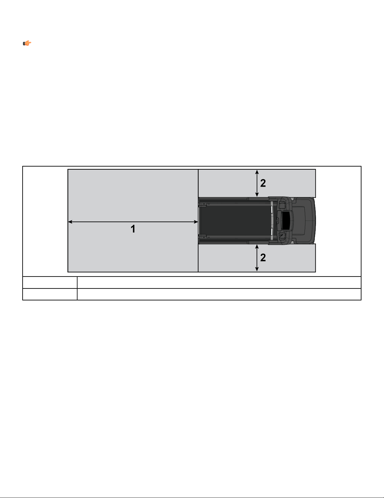
Safety Clearances
The following information is supplied as regional reference data regarding safety clearances around the exterior
of the treadmill.
• EU: The European EN ISO 20957 Safety Standard requires a 6.5 ft. (2 m) minimum from the rear of the treadmill
to any object or surface and at least as wide as the treadmill.
• U.S. and other regions: The ASTM International (ASTM ) F2115 - 12 Standard recommends the minimum
dimensions to be 1.64 ft. (0.5 m) on each side of the treadmill and 6.5 ft. (2 m) behind the rearward most portion
of the usable moving surface or 6.5 ft. (2 m) behind the furthest rearward obstruction to emergency egress from
the treadmill.
Free area
6.5 ft. (2.0m)
1
1.64 ft. (0.5m)2
After placing the unit where it will be used, check its stability. If there is even a slight rocking motion or the unit is
not stable, determine which stabilizing leg is not resting on the floor. To adjust, loosen the Jam Nut, and turn the
Stabilizing Leg until the rocking motion ceases, and both stabilizing legs rest firmly on the floor. Re tighten the
Jam Nut.
Page 10 of 31
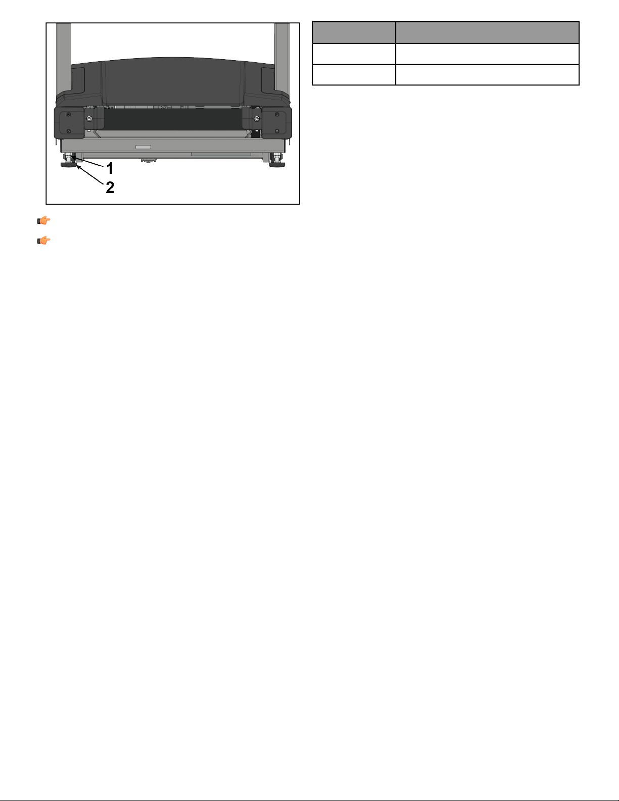
DescriptionItem
Jam Nut1
Stabilizing Leg2
Note: Stabilize the treadmill each time the unit is relocated.
Note: It is extremely important that the stabilizing leg be correctly adjusted for proper operation. An
unbalanced unit may cause striding belt misalignment. A bubble level is recommended to ensure proper
leveling.
Power Switch
Located on the front panel at the base of the treadmill, the ON/OFF switch has two positions: "I" (one) for ON and
"0" (zero) for OFF.
Page 11 of 31
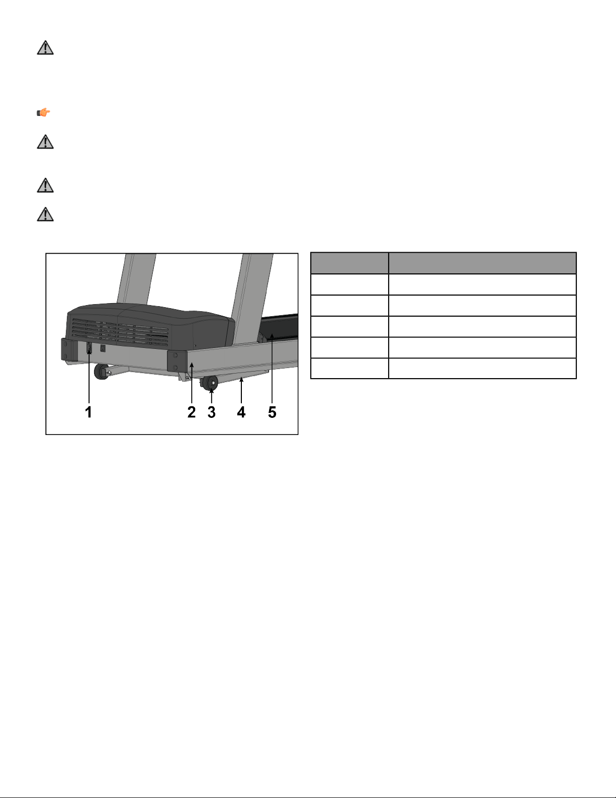
Power Cord Routing
Warning: Make sure the power cord is unplugged before attempting to route it around or through the
treadmill.
Connect the power cord to the power receptacle in the front of the treadmill. The power cord can be run to the
user-front left or right sides depending on installation / site needs.
Note: To accommodate treadmill incline, at least 2 ft. (24”) of power cord is required between the outlet
and the last power cord clip for outlets in front of the treadmill.
Warning: Keep the area 6.5 ft. (2 m) by 3 ft. (0.9 m) behind the treadmill clear of any obstructions, including
walls, furniture, and other equipment. Contact Customer Support Services for an optional longer power cord
if necessary.
Danger: Ensure that the power cord does not contact the striding belt or get pinched between the frame,
lift arm or under the wheels; failure to follow this warning may result in serious injury.
Danger: Assurez-vous que le cordon d’alimentation n’entre pas en contact avec le tapis et ne soit pas pincé
entre le cadre, le bras de levage ou sous les roues. Le non respect de cet avertissement peut provoquer de
graves blessures.
DescriptionItem
Power Receptacle1
Frame2
Wheel3
Lift Arm4
Striding Belt5
Page 12 of 31
Product Overview
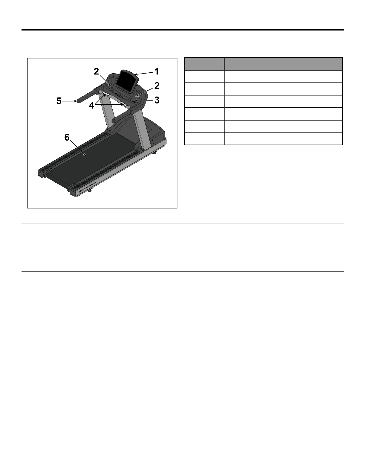
Product Features
DescriptionItem
Console1
Cup Holders2
Emergency Stop Lanyard3
Contact Heart Rate Sensors4
Handrails5
Striding Belt6
Mounting and Dismounting the Treadmill
Use the handrails to enhance stability when mounting or dismounting a treadmill. Never mount or dismount the
treadmill while the running belt is moving. Use the STOP button on the console to end a workout and stop the
running belt. Use the Emergency Stop System to stop the belt immediately.
User Position
The width of the moving walking/running surface is 20 in. (51 cm). Users must keep their feet within this width
while in motion. If standing on the stationary side rails, a user should ensure that his/her feet are completely on
the non-moving portion. Never step partially on the moving surface and partially on the non-moving surface
simultaneously.
• Users can adjust their fore-aft position on the moving belt as desired for reach to the console and handles,
clearance for arm swing and attachment of the safety stop pull cord. Do not step on the rear roller.
• It is recommended that the user run within the length of the side handrails to allow usage of the side arms to
dismount the belt if needed.
Page 13 of 31

Using and Testing the Emergency Stop System
The treadmill is equipped with an Emergency Stop System. The system consists of a rectangular stop magnet
(located on the upper bridge plastic) attached to a safety stop pull cord.
Before starting a workout, attach the lanyard on the safety stop pull cord to an item of the user's clothing. During
a workout, pull the cord to remove the magnet from the bridge. This will immediately stop the treadmill belt.
Note: Test the safety stop pull cord by attaching the lanyard to a user's item of clothing during operation
of the treadmill. While the treadmill is on and the console display is active, remove the safety stop pull cord
/ magnet from the bridge. A message will be displayed on the console similar to "Replace the emergency
stop switch". With the safety stop pull cord removed no keys shall function on the treadmill. Place the safety
stop pull cord back in place. The treadmill will reset and will be ready for operation.
Page 14 of 31

Assembly
Component and Hardware List
Components
QtyDescriptionItem
1Left Upright1
1Right Upright2
1Ergo™ Front Crossbar3
1Upper Dashboard Tray4
1Lower Dashboard Tray5
1Console6
2End Cap Front7
2End Cap Rear8
1Bridge9
1Console10
2Ergo™ Bar Backing Plate11
2Cable Tie12
Hardware
QtyDescriptionItem
8Bolt, 3/8 x 5” Hex Head1
8Washer, 3/8” Flat2
6Lock Nut, 3/8”3
8Bolt, M8 x 20mm Hex Head4
12Washer, M85
8Lock Nut, M86
2Plastic Grommet7
14Screw, M4.2 x 19mm Phillips Head8
4Screw, M5 x 25mm Phillips Head9
2Screw, #10 x 0.5” Phillips Head (silver)10
2Screw, #10 x 0.5” Phillips Head (black)11
Page 15 of 31
Tools Required
• Phillips screwdriver
• 9/16" Wrench (2)
• 9/16" Socket 3/8" Drive
• 13 mm Socket
• 13 mm Wrench
• 3" Extension 3/8" Drive
• 3/8” Drive ratchet
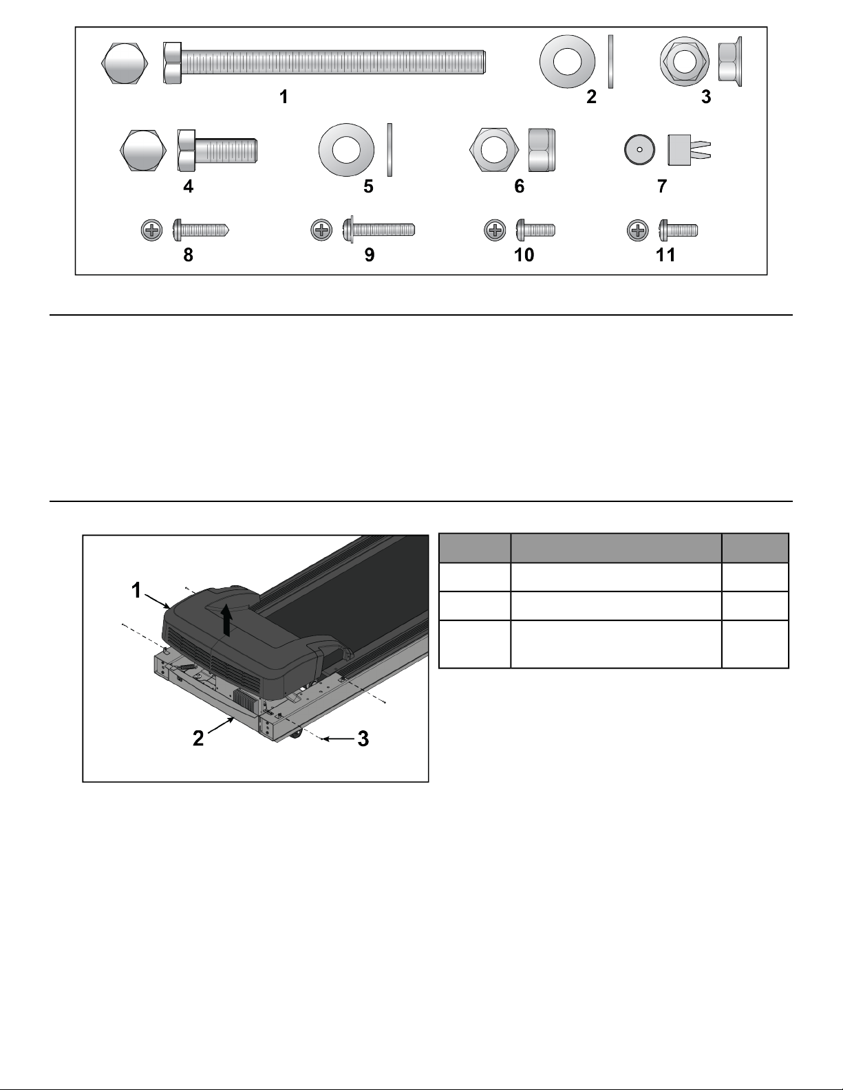
Remove Motor Cover
1. Remove screws securing motor cover to base assembly using a Phillips screwdriver.
QtyDescriptionItem
1Motor Cover1
1Base Assembly2
4
Screw, M4.2 x 19mm Phillips
Head
3
2. Remove motor cover.
Page 16 of 31
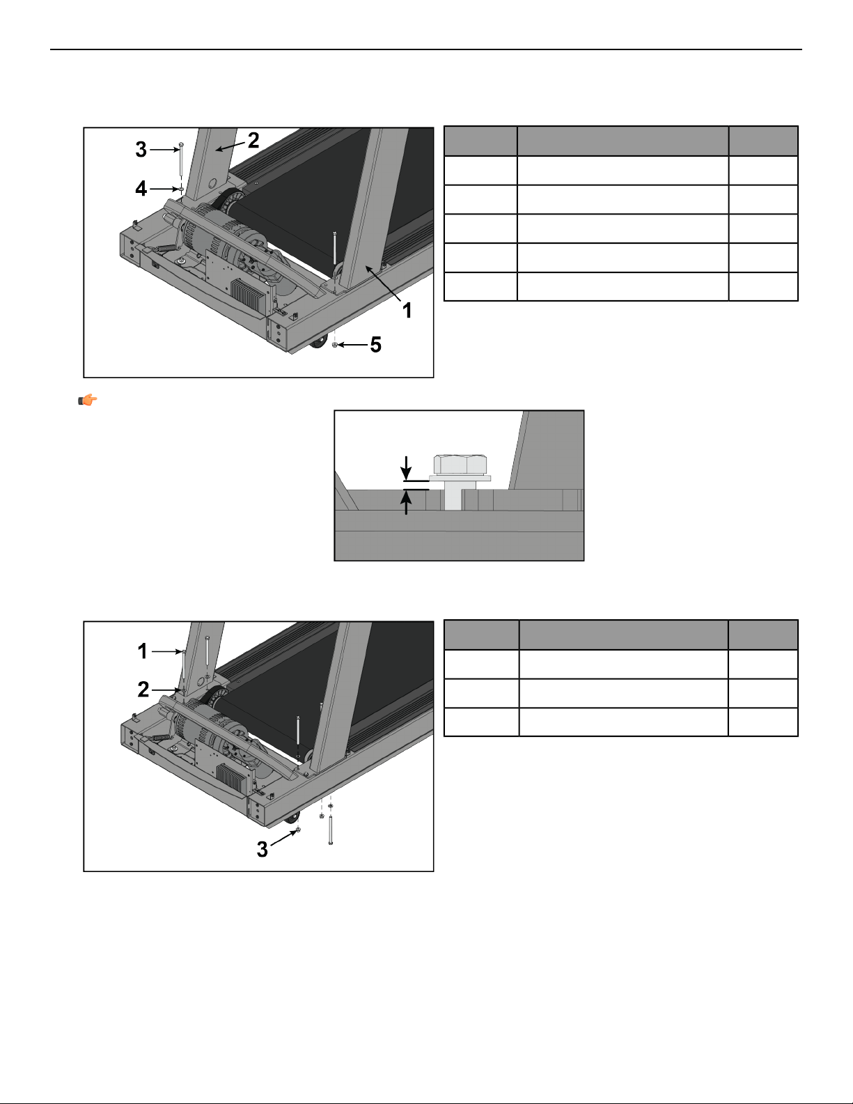
Install Uprights
1. Place uprights on base assembly.
2. Install one bolt, washer, and lock nut to left and right upright and base assembly using a 9/16" socket and
wrench.
QtyDescriptionItem
1Left Upright1
1Right Upright2
2Bolt, 3/8 x 5” Hex Head3
2Washer, 3/8” Flat4
2Lock Nut, 3/8"5
Note: Leave a spacing of 5-12mm between washer and upright.
3. Align uprights with holes in base assembly.
4. Install bolts, washers, and lock nuts securing uprights to base assembly using a 9/16" socket and wrench.
QtyDescriptionItem
6Bolt, 3/8 x 5” Hex Head1
6Washer, 3/8” Flat2
4Lock Nut, 3/8"3
Page 17 of 31
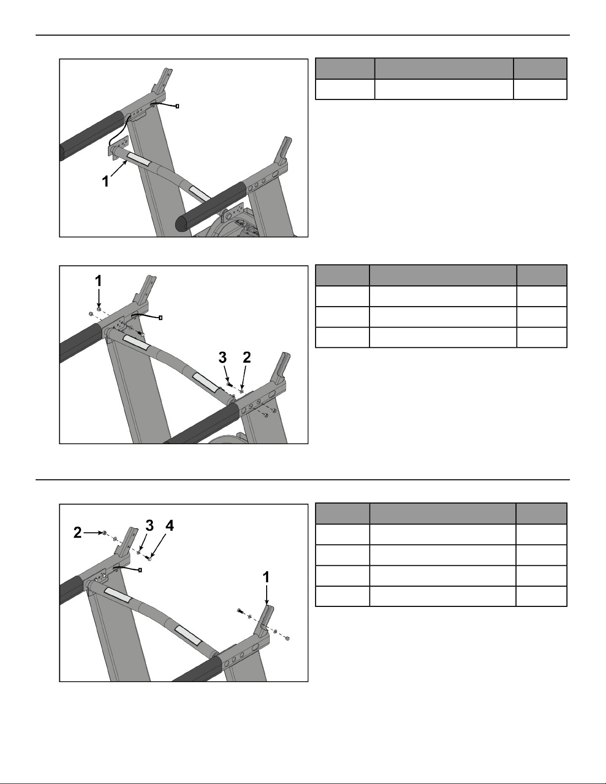
Install Front Crossbar
1. Route cable from front crossbar into left upright.
QtyDescriptionItem
1Ergo™ Front Crossbar1
2. Install bolts, washers, and lock nuts securing front crossbar to uprights using a 13mm socket and wrench.
QtyDescriptionItem
4Lock Nut, M81
4Washer, M82
4Bolt, M8 x 20mm Hex Head3
Install Bridge
1. Install a bolt, washers, and lock nut to each upright using a 13mm socket and wrench.
QtyDescriptionItem
2Upright1
2Lock Nut, M82
4Washer, M83
2Bolt, M8 x 20mm Hex Head4
Page 18 of 31
Note: Leave a spacing of 5-12mm between washer and upright.
2. Slide bridge down uprights.
QtyDescriptionItem
1Bridge1
2Upright2
3. Install bolts, washers, and lock nuts securing the bridge to uprights using a 13mm socket and wrench.
QtyDescriptionItem
1Bridge1
2Upright2
2Lock Nut, M83
4Washer, M84
2Bolt, M8 x 20mm Hex Head5
Page 19 of 31
Tighten Upper Hardware
Tighten hardware 100%.
QtyDescriptionItem
8Bolt, M8 x 20mm Hex Head1
Tighten Lower Hardware
Tighten hardware 100%.
QtyDescriptionItem
8Bolt, 3/8 x 5” Hex Head1
Install Plastic Grommets
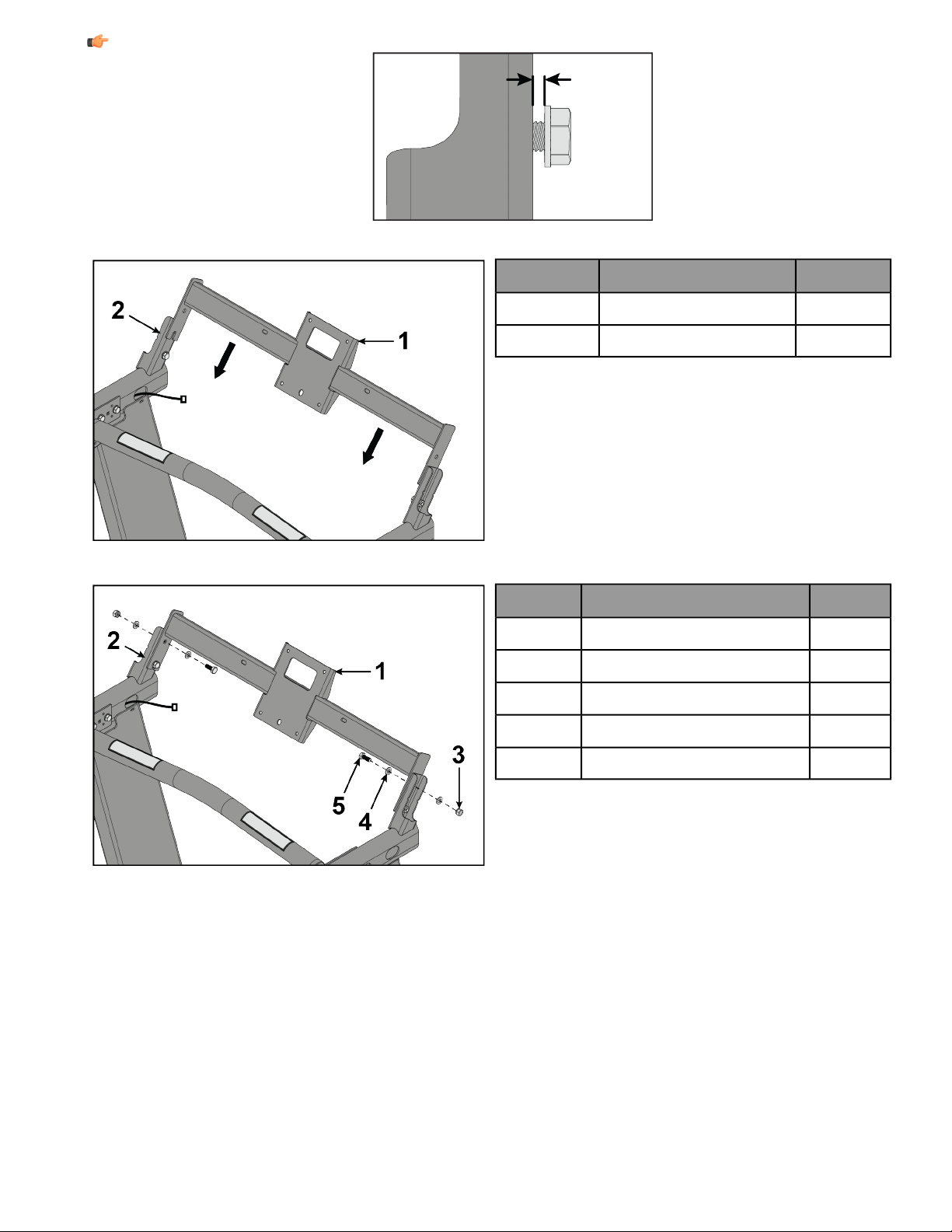
1. Secure cables from front crossbar and left upright to the bridge using cable ties.
2. Connect cables.
Page 20 of 31
3. Install plastic grommets to front crossbar.
QtyDescriptionItem
2Plastic Grommet1
2Cable Tie2
1Console Cable3
Note: For international units, install the ferrite approximately 7 inches from the center of the bridge.
Route console cable through ferrite and secure with cable tie.
QtyDescriptionItem
1Ferrite1
1Cable Tie2
1Console Cable3
Install Upper Dashboard Tray
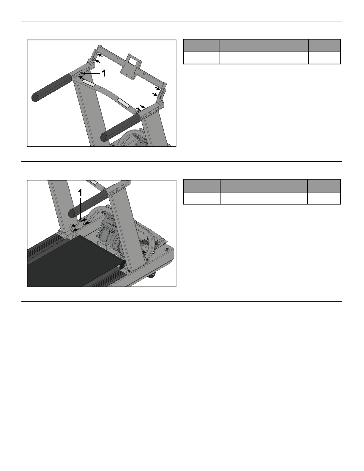
1. Install screws securing bar backing plate to front crossbar using a Phillips screwdriver.
QtyDescriptionItem
2Ergo™ Bar Backing Plate1
2
Screw, #10 x 0.5” Phillips Head
(black)
2
Page 21 of 31
2. Install screws securing upper dashboard tray to front crossbar using a Phillips screwdriver.
QtyDescriptionItem
1Upper Dashboard Tray1
2
Screw, M4.2 x 19mm Phillips
Head
2
Note: Be careful not to over tighten screws. Over tightening can damage the plastic.
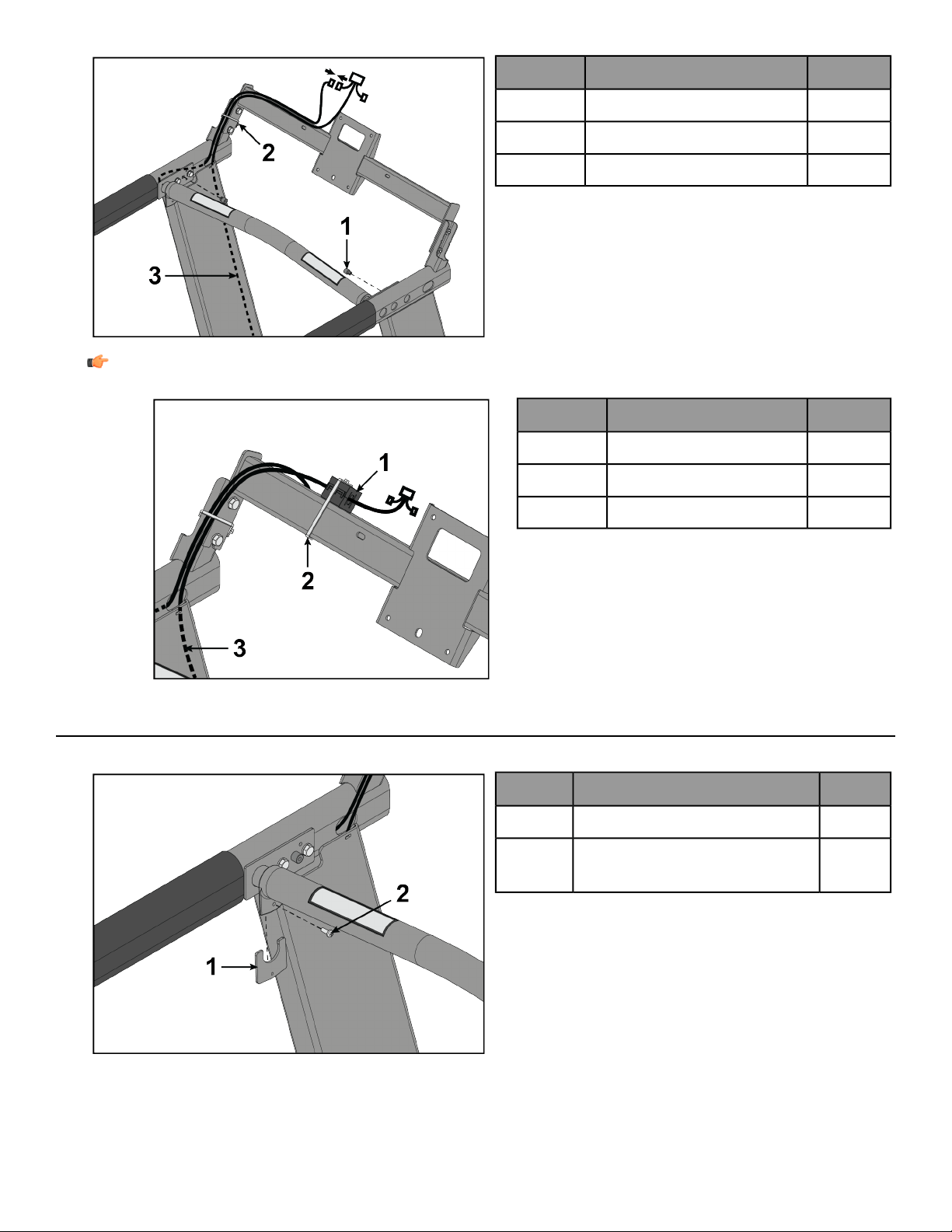
Install Console
1. Install screws securing console to upper dashboard tray using a Phillips screwdriver.
QtyDescriptionItem
1Console1
4
Screw, M5 x 25mm Phillips
Head
2
2. Connect cables.
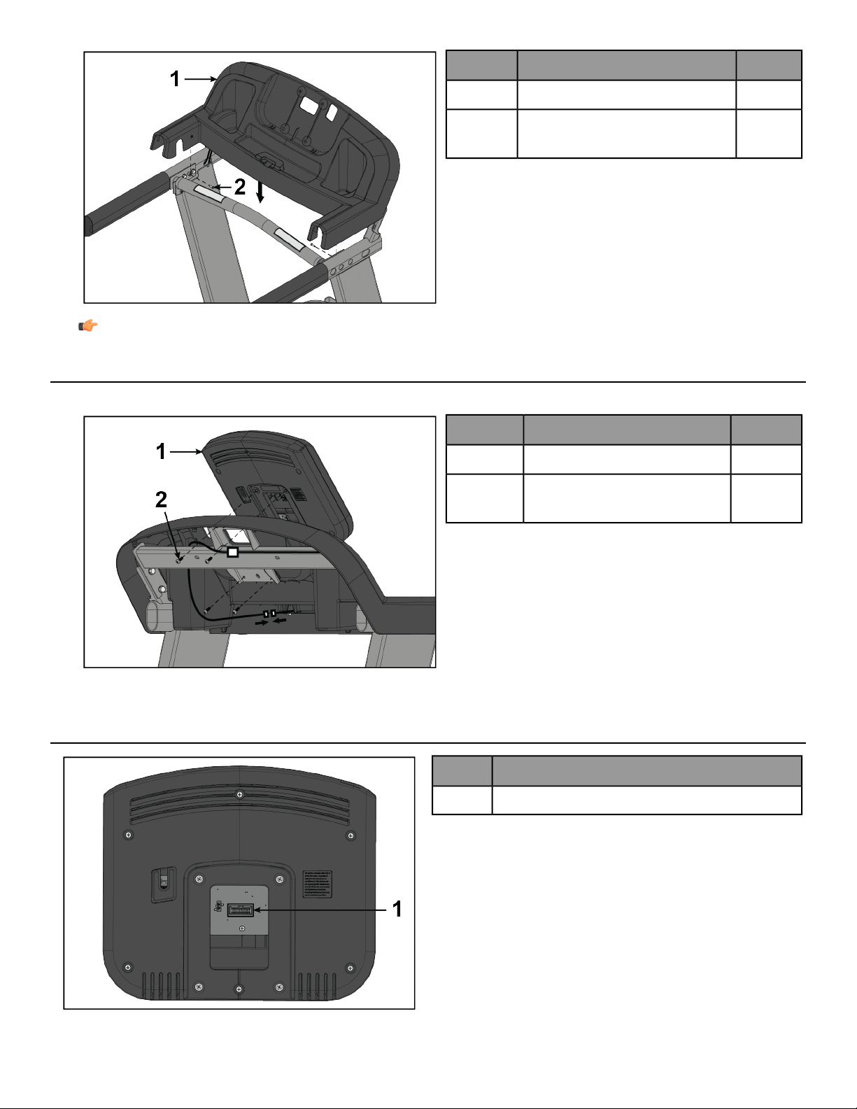
Console Connections
Description
Display Connection1
Page 22 of 31
Install Lower Dashboard Tray
Install screws securing lower dashboard tray to upper dashboard tray using a Phillips screwdriver.
QtyDescriptionItem
1Lower Dashboard Tray1
4Screw, M4.2 x 19mm Phillips Head2
2
Screw, #10 x 0.5” Phillips Head
(silver)
3
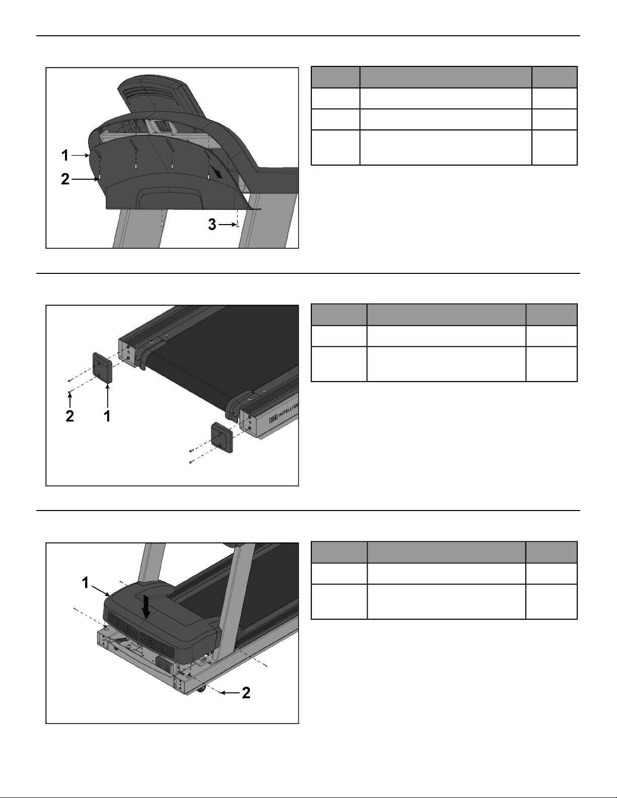
Install Rear End Caps
Install screws securing rear end caps to base assembly using a Phillips screwdriver.
QtyDescriptionItem
2Rear End Cap1
4
Screw, M4.2 x 19mm Phillips
Head
2
Install Motor Cover
Install screws securing motor cover to base assembly using a Phillips screwdriver.
QtyDescriptionItem
1Motor Cover1
4
Screw, M4.2 x 19mm Phillips
Head
2
Page 23 of 31
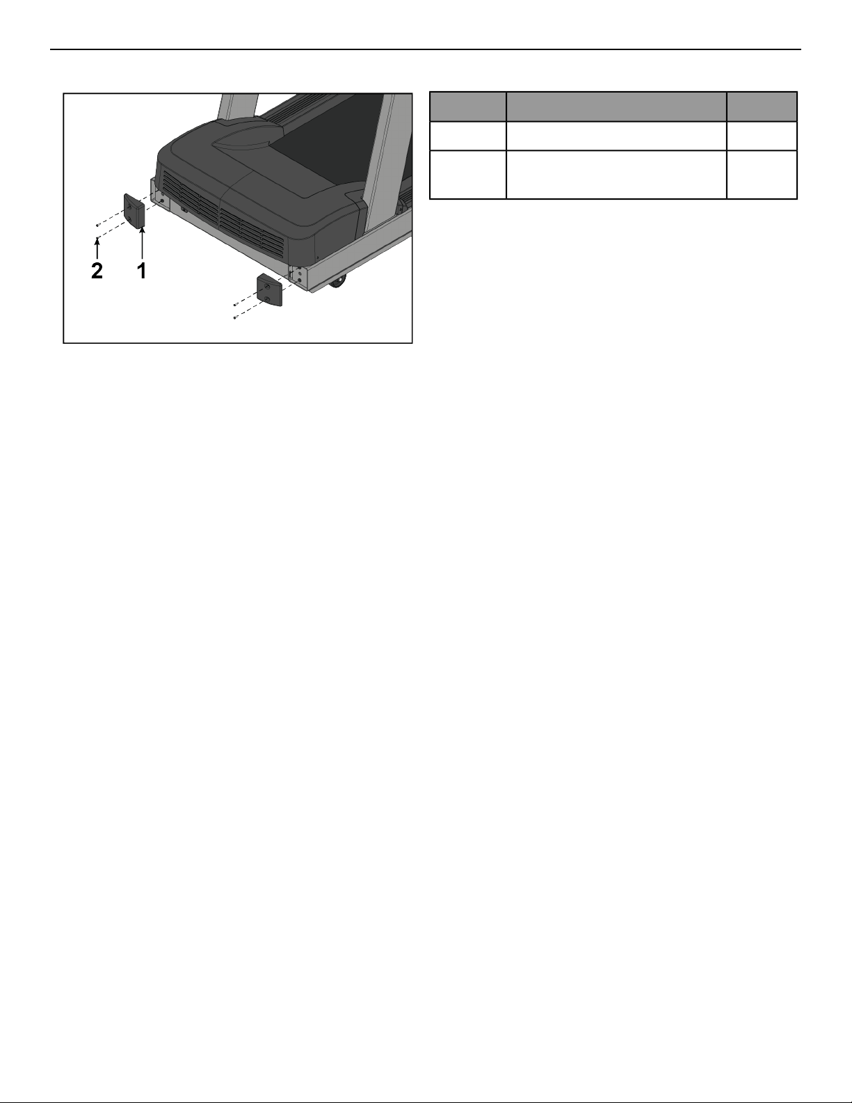
Install Front End Caps
Install screws securing front end caps to base assembly using a Phillips screwdriver.
QtyDescriptionItem
2Front End Cap1
4
Screw, M4.2 x 19mm Phillips
Head
2
Page 24 of 31

Service and Technical Data
Preventive Maintenance Tips
Note: Safety of the equipment can be maintained only if the equipment is examined regularly for damage
or wear. Keep the equipment out of use until defective parts are repaired or replaced. Pay special attention
to parts that are subject to wear, as outlined below.
Note: Pour assurer la sécurité du matériel,il convient de l'inspecter régulièrement afin de déceler tout signe
d'usure ou d'endommagement. N’utilisez pas l’appareil avant d’avoir réparé ou remplacé les pièces
défectueuses. Prêtez une attention particulière aux pièces sujettes à usure, tel que décrit ci-dessous.
The following preventive maintenance tips will keep the product operating at peak performance:
• Locate the product in a cool, dry place.
• Clean the display console and all exterior surfaces with an approved or compatible cleaner (see Approved and
Compatible Cleaners) and a microfiber cloth.
• Long fingernails may damage or scratch the surface of the console; use the pad of the finger to press the selection
buttons on the console.
• Check operation of the emergency stop system once a week.
• Inspect and vacuum the area directly surrounding and under the unit regularly.
• Vacuum around the striding belt regularly to keep debris from accumulating.
• Inspect exterior parts regularly for wear, particularly the striding belt, deck and line cord.
• Check to make sure the unit is properly leveled.
• Check the position (centering) of the striding belt.
Note: Normal belt operating position is for the belt to be located within the belt travel indicators on the
rear roller guards. Refer to Tracking (Centering) A Striding Belt or contact Customer Support Services for
proper alignment instructions.
Approved and Compatible Cleaners
Two preferred cleaners have been approved by reliability experts: PureGreen 24 and Gym Wipes. Both cleaners
will safely and effectively remove dirt, grime and sweat from equipment. PureGreen 24 and the Antibacterial Force
formula of Gym Wipes are both disinfectants that are effective against MRSA and H1N1.
PureGreen 24 is available in a spray which is convenient for gym staff to use. Apply the spray to a microfiber cloth
and wipe down the equipment. Use PureGreen 24 on the equipment for at least 2 minutes for general disinfection
purposes and at least 10 minutes for fungus and viral control.
Gym Wipes are large, durable pre-moistened wipes to use on the equipment before and after workouts. Use Gym
Wipes on the equipment for at least 2 minutes for general disinfection purposes.
Contact Customer Support Services to order these cleaners (1-800-351-3737 or email:
Mild soap and water or a mild non-abrasive household cleanercan also be used to clean thedisplay and all exterior
surfaces. Use a soft microfiber cloth only. Apply the cleaner to the microfiber cloth before cleaning. DO NOT use
ammonia or acid based cleaners. DO NOT use abrasive cleaners. DO NOT use paper towels. DO NOT apply cleaners
directly to the equipment surfaces.
Page 25 of 31

Preventive Maintenance Schedule
BiannuallyMonthlyWeeklyItem
InspectCleanConsole Overlays
InspectCleanBottle Holders / Accessory Trays
InspectConsole Mounting Bolts
InspectHardware
InspectCleanFrame
InspectCleanPlastic Covers
Clean / InspectLifepulse Sensors
InspectStriding Belt Centered
Clean / InspectEmergency Stop Magnet
Vacuum / CleanCleanMotor Cover
InspectMotor Electronic Compartment
InspectDrive Belt
Inspect / AdjustLeg Levelers
InspectFront and Rear Rollers
InspectCleanSide Step Area
InspectCleanSide Hand Rails
InspectCleanErgo™ Front Handlebar
Troubleshooting the Treadmill
No power
Corrective ActionProbable Cause
Turn the switch to the ON position.ON / OFF switch is not in proper position.
Plug treadmill into an appropriate circuit. Refer to Grounding
Instructions.
Note: In North America use a dedicated 20 amp circuit.
Using a voltmeter, verify power at outlet. If no power exists, reset
circuit breaker at panel.
Power source is insufficient.
Replace line cord. Contact Customer Support Services.Line cord is damaged.
Inspect power connections at wall outlet and at machineforproper
contact.
Line cord is improperly seated in socket.
Striding belt slips off- center.
Corrective ActionProbable Cause
Check levelers and level treadmill. Check striding belt & re-tension
as necessary. Refer to How to Adjust and Tension the Striding Belt.
Floor surface is uneven.
Page 26 of 31

Maximum speed is reduced.
Corrective ActionProbable Cause
Instruct users not to push striding belt in either direction.
User is pushing striding belt. This occurs when the runner is running
faster than the striding belt will travel, with the result of the striding
belt being pushed with the runner’s feet.
User is stalling striding belt. This occurs with heavier users at lower
striding belt speeds. The striding belt will "stall" if the user is
traveling slower than the striding belt.
Replace belt and deck.
Striding belt/deck malfunctions. Thedeck laminate is worn through
or the underside of striding belt is glazed over (hard, glossy).
Plug treadmill into an appropriate circuit. Refer to Grounding
Instructions.
Note: In North America use a dedicated 20 amp circuit.
Power source is insufficient.
Rubbing sound comes from underneath machine.
Corrective ActionProbable Cause
Power down theunit and disconnect AC power. Inspect underneath
striding belt and machine. Remove any debris or objects that may
cause interference with the treadmill.
Foreign objects may be stuck underneath the machine.
Display does not illuminate when machine is powered on.
Corrective ActionProbable Cause
Check all electrical connections for proper attachment.
• AC outlet and line cord
• Line cord at treadmill
• Power switch
• All console connections
• All lower electronics connections
Contact Customer Support Services.
• No power.
• Loose connection(s).
• Incorrect console or power supply.
Unit resets randomly or pauses.
Corrective ActionProbable Cause
Plug treadmill into an appropriate circuit. Refer to Grounding
Instructions.
Note: In North America use a dedicated 20 amp circuit.
Power source is insufficient.
Replace line cord.Damaged ground prong is on line cord.
Inspect power connection at electrical outlet and at machine for
proper contact.
Line cord improperly seated in electrical outlet.
Re-engage the emergency stop magnet.Emergency stop magnet is not engaged.
Move all possible obstructions off display console and handlebar.
Towel or other item may be making contact with stop switch while
user is running.
Page 27 of 31
Corrective ActionProbable Cause
Contact Customer Support Services.
Stop switch is activated with very light pressure or returns slowly
after being pressed.
Stop switch cable is not making proper contact.
Main wire harness is pinched.
Ground path is open.
How to Adjust and Tension the Striding Belt
Do not move the treadmill or place hands under the treadmill while it is plugged into an electrical outlet!
The Belt Tensioning Bolts
An 8mm hex key wrench is required for this task. The treadmill has access holes in the rear roller guards which
allow access to the tensioning bolts. These tensioning bolts make it possible to adjust the tracking and centering
of the striding belt without removing the guards.
Note: It is extremely important that the treadmill be correctly leveled prior to any tracking adjustments. An
unstable unit may cause striding belt misalignment. See How To Stabilize the Treadmill prior to attempting
any rear roller adjustments.
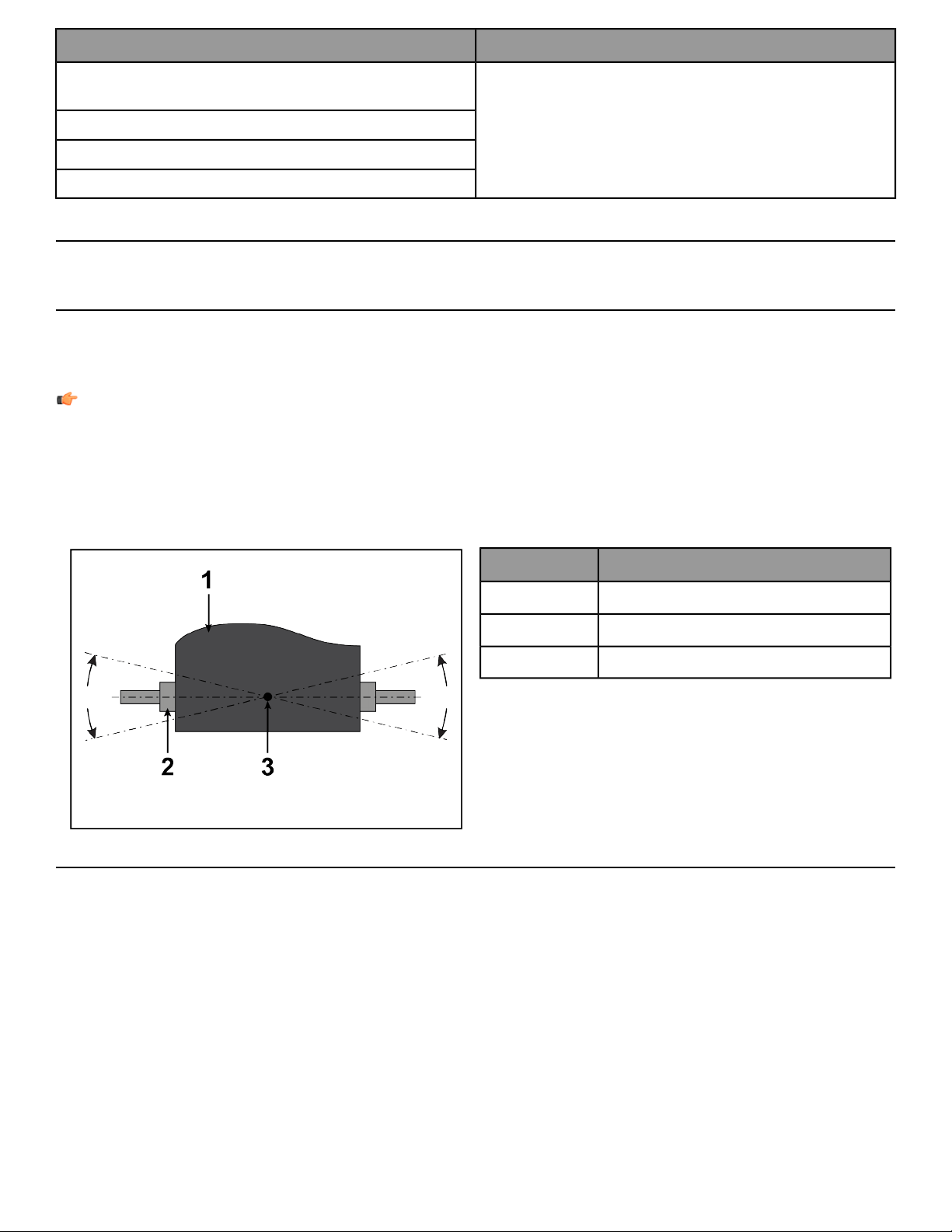
Before proceeding, it is helpful to visualize the pivot point of the rear roller. Each adjustment made to one side of
the roller must be met with an equal and opposite adjustment to the other side of the roller to maintain an ideal
belt tension at the pivot point.
DescriptionItem
Belt1
Rear Roller2
Pivot Point of Rear Roller3
Tracking (Centering) A Striding Belt
Two people are needed to perform this procedure.
1. Locate the two access holes to the belt tensioning bolts on each of the rear roller guards.
2. One person stands on the side rails of the treadmill and straddles the belt. This person presses GO and sets
the belt speed to 2.5 MPH (4.0 KPH).
Page 28 of 31

3. If the striding belt has moved to the right, the second person turns the right tension bolt a quarter-turn clockwise
and then turns the left tension bolt a quarter-turn counter-clockwise to make the striding belt track back to
the center of the roller. If the striding belt has moved to theleft, turn the left tension bolt a quarter-turn clockwise
and then turn the right tension bolt a quarter-turn counter-clockwise to make the striding belt track back to
the center of the roller.
Note: If the striding belt has moved as far as to the edge of the roller (either right or left side), it must
be re-centered per the above procedure.
4. Repeat the adjustments until the striding belt appears centered. Allow the machine to continue running for
several minutes at 4.0 MPH. (6.4 KPH) to observe if tracking remains stabilized.
Note: Do not exceed one full turn of the adjusting screws in either direction. If after one full turn the belt
does not track properly, contact Cybex International, Inc. Customer Support. Do not overtighten the
tensioning bolts while making belt adjustments. Overtightening of bolts may over stretch and damage
the striding belt or roller.
Tensioning an Existing Striding Belt
1. Press GO and operate the treadmill for five minutes at 5.0 MPH (8.0 KPH).
Note: Do not run or walk on belt!
2. Reduce the speed to 2.0 MPH (3.2 KPH). Walk on the treadmill. Tightly grip the handrails and apply force with
feet on the striding belt near the motor cover against the moving belt direction. If the belt slips, continue to
Step 3. If it does not slip, the tension is correct.
3. Using the STOP key, stop the treadmill. Turn the belt tensioning bolts a quarter-turn clockwise for each side.
4. Repeat STEPS 2 and 3 until the belt no longer slips. Do not exceed one full turn (four quarter turns) per side
when adjusting the belt tensioning bolts.
5. Press GO, operate the treadmill at 2.0 MPH (3.2 KPH) and check to insure proper tracking (see Tracking
(Centering) A Striding Belt). If the striding belt drifts to the left or right see Centering an Existing or New Striding
Belt .
Do not overtighten the tensioning bolts while making belt adjustments. Overtightening of bolts may over
stretch and damage the striding belt or roller bearings. Do not exceed one full turn of either bolt in either
direction.
How To Obtain Product Service
1. Verify the symptom and review the operating instructions. The problem may be unfamiliarity with the product
and its features and workouts.
2. Locate and write down the serial number of the unit which is located on the back of the unit near the toe
guard.
3. Contact Customer Support at http://www.lifefitness.com.
Page 29 of 31

Specifications
V Series Treadmill - Specifications
Heavy / Commercial, EN ISO 20957 Class SDesigned Use
400 lbs. / 181 kgMaximum User Weight
0.5 - 12.0 MPH (0.8 - 19.3 KPH) in 0.1 incrementsSpeed Range
0% - 15%Incline Range
AC motor with variable speed controllerDrive Train
AC InductionMotor Type
4.0 HP continuous duty, 8.0 HP peakMotor Size
See Electrical Requirements for requirements outside the U.S.
Power Requirements
Dedicated 120 volt, 20 amp (U.S)
2.75” (70 cm) diameter, precision-crowned, front and backRollers
60” Length x 20” Width (152 cm Length x 51 cm Width) (pre-lubricated)Striding Belt
2-ply, polyester weave, anti-slip PU top cover, antistaticBelt Type
3/4" Medium Density Fiberboard (MDF), reversibleDeck Type
Intelligent Suspension IS4Shock Absorption System
16" (41 cm) flaredSide Handrail
Red magnetic lanyard emergency stop systemStop Systems
Patented Lifepulse™ digital contact heart rateHeart Rate Monitoring Systems
F-type connectorCATV (1)
Shipped Dimensions (without console)Physical Dimensions (with console)
85 in. / 216 cm80.68 in. / 204.93 cmLength
40 in. / 101.6 cm32.098 in. / 81.53 cmWidth
25 in. / 63.5 cm57 in. / 145 cmHeight
346 lbs. / 157 kg325 lbs. / 147.42 kgWeight
Page 30 of 31

Columbia Center III - 9525 West Bryn Mawr Ave, Rosemont, IL 60018 • 800-351-3737 • 847-288-3700 • FAX 800-216-8893
www.cybexintl.com