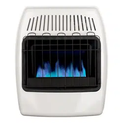
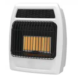
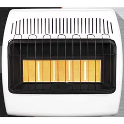
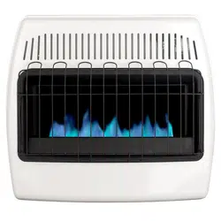
User Manual Convection Wall Heater
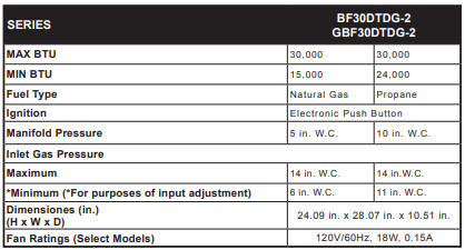
PRODUCT FEATURES
SAFETY PILOT
This heater has a pilot with an Oxygen Depletion Sensing (ODS) safety shutoff system. The ODS/pilot shuts off the heater if there is not enough fresh air and cuts off main burner gas in the event of flame out.
DUAL FUEL CAPABILITY
Your heater is equipped to operate on either propane or natural gas. The heater is shipped from the factory ready for connecting to propane. The heater can easily be changed to natural gas by having your qualified installer follow the instructions on page 11 and the markings on the heater.
LEG KIT(SELECT MODELS)
2 support legs and 4 support leg screws are included for floor mounting the heater. See page 13.
NOTE: This is an optional accessory and is not required for operation of the heater.
ELECTRONIC PUSH BUTTON IGNITION SYSTEM
This heater is equipped with an electronic push button ignition system. This system requires one AAA battery (provided).
THERMOSTAT HEAT CONTROL(SELECT MODELS)
The control automatically cycles the burner on and off to maintain a desired room temperature. See page 24.
FAN KIT(SELECT MODELS)
The fan kit helps to distribute the warmed air into the space more rapidly
LOCAL CODES
Install and use heater with care. The installation must conform with local codes or, in the absence of local codes, with the latest edition of The Nation Fuel Gas Code, ANSI Z223.1/NFPA 54
PREPARING FOR INSTALLATION
UNPACKING
1. Remove heater from carton.
2. Remove all protective packaging applied to heater for shipping
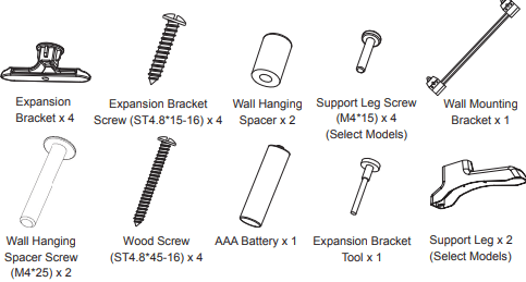
3. Verify all contents are present.
NOTE: Support Leg Screw (M4*15) (Select Models), Wood Screw (ST4.8*45-16), Expansion Bracket Screw (ST4.8*15-16), and Expansion Bracket come with (2) extra each.
4. Check heater for any shipping damage. If heater is damaged, promptly inform dealer where you bought the heater.
WATER VAPOR: A BY-PRODUCT OF UNVENTED ROOM HEATERS
Water vapor is a by-product of gas combustion. An unvented room heater produces approximately one (1) ounce (30 mL) of water for every 1,000 BTUs (0.3 Kw) of gas input per hour. An unvented room heater is intended as a supplemental heater rather than a primary heat source. In most supplemental heat applications, the water vapor does not create a problem. In most applications, the water vapor enhances the low humidity atmosphere experienced during cold weather.
The following steps will help ensure that water vapor does not become a problem:
1. Be sure the heater is the proper size for the application, including adequate combustion air and circulation air.
2. If there is high humidity, a dehumidifier may be used to help lower the water vapor content of the air.
3. Do not use an unvented room heater as the primary heat source.
AIR FOR COMBUSTION AND VENTILATION
CAUTION: This heater shall not be installed in a room or space unless the required volume of indoor combustion air is provided by the method described in the National Fuel Gas Code, ANSI Z223.1/NFPA54, the International Fuel Gas Code, or applicable local codes.
PRODUCING ADEQUATE VENTILATION
All spaces in homes fall into one of the three following ventilation classifications:
1. Unusually Tight Construction
2. Unconfined Space
3. Confined Space
The information on pages 7 through 9 will help you classify your space and provide adequate ventilation.
Confined and Unconfined Space
A confined space as a space whose volume is less than 50 cu. ft. per 1,000 BTU/hr (4.8 m^3 per kw) of the aggregate input rating of all appliances installed in that space and an unconfining space as a space whose volume is not less than 50 cu. ft. per 1,000 BTU/hr (4.8 m^3 per kw) of the aggregate input rating of all appliances installed in that space. Rooms connecting directly with the space in which the appliances are installed*, through openings not furnished with doors, are considered a part of the unconfined space. This heater shall not be installed in a confined space or unusually tight construction unless provisions are provided for adequate combustion and ventilation air.
* Adjoining rooms are connecting only if there are doorless passageways or ventilation grills between them.
Unusually Tight Construction
The air that leaks around doors and windows may provide enough fresh air for combustion and ventilation. However, in buildings of unusually tight construction, you must provide additional fresh air.
Unusually tight construction is defined as construction where:
a) walls and ceilings exposed to the outside atmosphere have a continuous water vapor retarder with a rating of one perm (6x10-11kg per pa-sec-m2) or less with openings gasketed or sealed and
b) weather stripping has been added on windows that can be opened and on doors and
c) caulking or sealants are applied to areas such as joints around window and door frames, between sole plates and floors, between wall-ceiling joints, between wall panels, at penetrations for plumbing, electrical, and gas lines, and at other openings.
If your home meets all of the three criteria above, you must provide additional fresh air. See “Ventilation Air From Outdoors” (page 9). If your home does not meet all of the three criteria above, proceed to “Determining Fresh-Air Flow For Heater Location”.
DETERMINING FRESH-AIR FLOW FOR HEATER LOCATION
Determining if You Have a Confined or Unconfined Space
Use this worksheet to determine if you have a confined or unconfined space.
Space: Includes the room in which you will install heater plus any adjoining rooms with doorless passageways or ventilation grills between the rooms.
1. Determine the volume of the space Length × Width × Height = cu. ft. (volume of space) Example: Space size 20 ft. (length) × 16 ft.(width) × 8 ft. (ceiling height) = 2560 cu. ft. (volume of space)
If additional ventilation to adjoining room is supplied with grills or openings, add the volume of these rooms to the total volume of the space.
2. Divide the space volume by 50 cu. ft. to determine the maximum BTU/hr the space can support. _______ (volume of space) ÷ 50 cu. ft.= (Maximum BTU/hr the space can support) Example: 2560 cu. ft. (volume of space) ÷ 50 cu. ft. = 51.2 or 51,200 (maximum BTU/hr the space can support)
3. Add the BTU/hr of all fuel burning appliances in the space.
Vent-free heater _________ BTU/hr
Gas water heater* ________BTU/hr
Gas furnace _____________BTU/hr
Vented gas heater ________BTU/hr
Example: Gas heater logs __________BTU/hr
Gas water heater 30,000 BTU/hr
Other gas appliances*+ ____BTU/hr
Vent-free heater + 26,000 BTU/hr
Total = ____BTU/hr Total = 56,000 BTU/hr
*Do not include direct-vent gas appliances. Direct-vent draws combustion air from the outdoors and vents to the outdoors.
4. Compare the maximum BTU/hr the space can support with the actual amount of BTU/hr used.
_______ BTU/hr (maximum the space can support)
_______ BTU/hr (actual amount of BTU/hr used).
Example : 51,200 BTU/hr (maximum the space can support) 56,000 BTU/hr (actual amount of BTU/hr used) The space in the above example is a confined space because the actual BTU/hr used is more than the maximum BTU/hr the space can support. You must provide additional fresh air. Your options are as follows:
a) Rework worksheet, adding the space of an adjoining room. If the extra space provides an unconfined space, remove door to adjoining room or add ventilation grills between rooms. See “Ventilation Air From Inside Building,” page 9.
b) Vent room directly to the outdoors. See “Ventilation Air From Outdoors”, page 9.
c) Install a lower BTU/hr heater if lower BTU/hr size makes room unconfined. If the actual BTU/hr used is less than the maximum BTU/hr the space can support, the space is an unconfined space. You will need no additional fresh air ventilation.
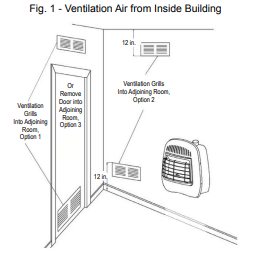
Ventilation Air From Inside Building
This fresh air would come from adjoining unconfined space. When ventilating to an adjoining unconfined space, you must provide two permanent openings: one within 12 in. of the wall connecting the two spaces (see options 1 and 2, Fig. 1). You can also remove door into adjoining room (see option 3, Fig. 1). Follow the National Fuel Gas Code NFPA 54/ANS Z223.1. Air for Combustion and Ventilation for required size of ventilation grills or ducts.
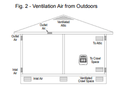
Ventilation Air From Outdoors
Provide extra fresh air by using ventilation grills or duct. You must provide two permanent openings: one within 12 in. of the ceiling and one within 12 in. of the floor. Connect these items directly to the outdoors or spaces open to the outdoors. These spaces include attics and crawl spaces. Follow the National Fuel Gas Code NFPA 54/ANS Z223.1. Air for Combustion and Ventilation for required size of ventilation grills or ducts.
IMPORTANT: Do not provide openings for inlet or outlet air into attic if attic has a thermostat-controlled power vent. Heated air entering the attic will activate the power vent. Rework worksheet, adding the space of the adjoining unconfined space. The combined spaces must have enough fresh air to supply all appliances in both spaces.
INSTALLATION
CLEARANCES TO COMBUSTIBLES
Carefully follow the instructions below. This heater can be mounted on the wall or on the floor using the support legs (Select models).
WARNING: Maintain the minimum clearances shown in (See Fig. 3). If you can, provide greater clearances from floor, ceiling, and joining wall.
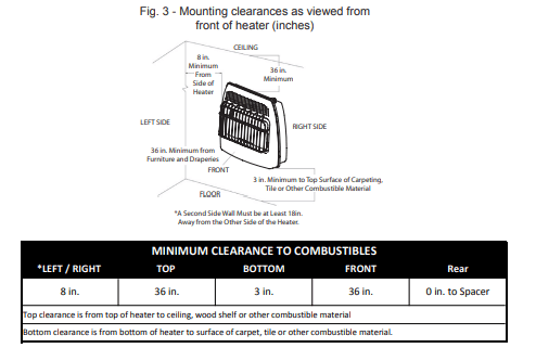
*A second side wall must be at least 18 in. away from the other side of the heater. Always maintain a minimum of 36 in. clearance from furniture and draperies.
*For the installation in residential garages please refer to the bottom of page 3.
GAS SELECTION
CAUTION: The knob to the gas selection means shall not be accessed or adjusted while the appliance is in operation
WARNING
- Gas selection should only be done by a qualified technician.Gas selection should only be done by a qualified technician.
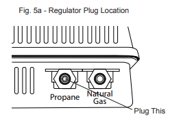
- The unused regulator must be fitted with a metal plug with a pipe thread sealant.
- Failure to plug the unused regulator may result in a fire, property damage, personal injury, or death.
Units to be used with LP
Remove the plug from the inlet of the LP regulator; do not make any further adjustments. Proceed to installing the gas line as instructed in the Owner’s Manual.
LP TO NG Conversion
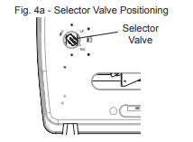
1. Before gas conversion, remove screws and access panel for selector valve.
2. The gas selector valve should be in the LP position. Push and turn the selector knob clockwise until the knob locks into the NG position (See Fig. 4a). The selector valve must be locked in the NG position. DO NOT operate the heater between the locked positions.
3. Remove plug from the inlet of the NG regulator.
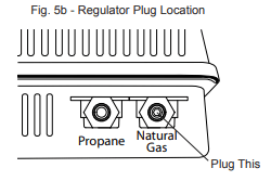
4. If the LP plug was removed previously, apply thread sealant to ensure that there are no leaks and install the NG plug into the inlet of the LP regulator and tighten firmly. (See Fig 5a and 5b).
5. Replace selector valve access panel.
NG TO LP CONVERSION
1. Before gas conversion, remove screws and access panel for selector valve.
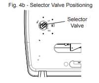
2. The gas selector valve should be in the NG position. Push and turn the selector knob counter clockwise until the knob locks into the LP position (See Fig. 4b). The selector valve must be locked in the LP position. DO NOT operate the heater between the locked positions.
3. Remove plug from the inlet of the LP regulator.
4. Using thread sealant to ensure there are no leaks, replace plug into the inlet of the NG regulator and tighten firmly (See Fig. 5b).
5. Replace selector valve access panel.
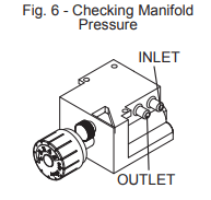
IMPORTANT: Before proceeding with the installation, the qualified ser- vice technician converting the heater between gas supplies must verify correct manifold pressure. A reading can be taken using a pressure gauge and the appropriate pressure tap (See Fig. 6).
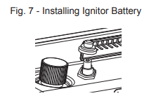
INSTALLING IGNITOR BATTERY
- Battery is included.
- Unscrew ignitor cap and insert included battery negative (flat) side down (See Fig. 7). Replace Ignitor cap.
- Be sure to observe proper polarity (+/-) when installing or re- placing the battery. Damage due to improper battery installa- tion may void the warranty on the product.
- Install/replace the battery according to the type and quantity stated in table below.
- Remove battery when depleted.
- For long periods of non-operation, remove the battery from all components for safety
Do NOT dispose of batteries in fire. Improper disposal may cause batteries to leak or explode.
INSTALLING FAN(OPTIONAL)
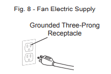
WARNING: Electrical Grounding Instructions This appliance is equipped with a three-prong (grounding) plug for your protection against shock hazard and should be plugged directly into a properly grounded three-prong receptacle (See Fig. 8).
1. Wall mounted heater must be disconnected from gas supply and removed from wall before installing fan accessory. Contact a qualified service person to do this.
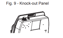
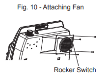
2. Remove fan knock-out panel using a screwdriver (See Fig. 9). Attach Fan to the rear panel of the heater using the four screws provided.
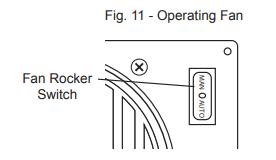
NOTE: Be sure the rocker switch is positioned in the upper right corner. (See Fig. 10).
3. This fan is equipped with manual “MAN” and automatic “AUTO” settings (See Fig. 11 on page 13). Set the rocker switch to “MAN” for manual mode, allowing the fan to continuously run until the rocker switch is returned to the OFF “O” position. Set the rocker switch to “AUTO” for the automatic mode, which will turn the fan on and off based on ambient room temperature. It may take 5 to 10 minutes for the fan to come on when the unit is cold.
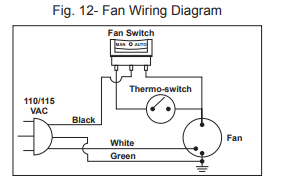
NOTE: If any of the original wire as supplied with the appliance must be replaced, it must be replaced with a wire of at least an equal tem- perature rating. Refer to Fig. 12 on page 13 for wiring diagram.
LOCATING HEATER
This heater is designed to be mounted on a wall or on a floor, using the Support Legs (Select Models) includ- ed with select models.
For convenience and efficiency, install heater:
1. Where there is easy access for operation, inspection, and service.
2. In the coldest part of room.
3. A minimum of 3' away from furniture and draperies
FLOOR MOUNTING (SELECT MODELS)
(Cannot be done in bedroom or bathroom)
(Cannot be used for garage and ice-house heaters)
NOTE: This is an optional accessory and is not required for operation of the heater
Before installing Support Legs to heater base, please make sure you have the following items:
(2) Support Legs
(4) Support Leg Screws (M4*15)
1. Set down a blanket onto the table where the heater will be placed for leg installation to prevent scratch- ing of the table and/or the heater.
2. Set back of heater on table with the bottom of heater extending outside the table edge.
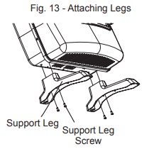
3. Fasten Support Legs to heater using Support Leg Screws (Fig.13)
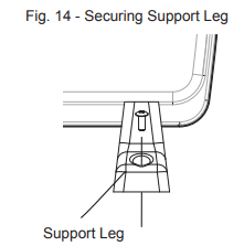
4. Once positioned, secure heater to the floor using Support Leg Screws (M4*15) and mounting holes found on heater Support Legs (See Fig. 14).
WALL MOUNTING
WARNING: Failure to position the parts in accordance with these diagrams or failure to use only parts specifically approved with this heater may result in property damage or personal injury.
Mounting Bracket
The mounting bracket is located separately from the unit, but packed inside the same box.
Methods For Attaching Mounting Bracket To Wall
Use only the last hole on each end of mounting bracket to attach bracket to wall. Attach mounting bracket to a wall only in one of two ways:
1. Attaching to wall stud: This method provides the strongest hold. Insert wood screws (ST.8*45-16) through mounting bracket and into wall studs.
2. Attaching to expansion bracket: This method allows you to attach mounting bracket to hollow walls (wall areas between studs) or to solid walls (concrete or masonry).
Decide which method better suits your needs. Either method will provide a secure hold for the mounting bracket.
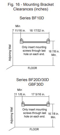
Marking Screw Locations
1. Tape mounting bracket to wall where heater will be located. Make sure mounting bracket is level.
2. Mark screw locations on wall (See Fig. 16).
Note: Mark only last hole on each end of mounting bracket. Insert (2) wood screws (ST.8*45-16) total through these holes only.
3. Remove tape and mounting bracket from wall.
Attaching Mounting Bracket To Wall
Note: Expansion bracket, wood screws (ST.8*45-16), and wall hanging spacers are in hardware package. The hardware package is provided with heater.
Attaching to Wall Stud Method
For attaching mounting bracket to wall studs:
1. Drill holes at marked locations using 9/64-inch drill bit.
2. Place mounting bracket onto wall. Line up last hole on each end of bracket with holes drilled in wall.
3. Insert wood screws (ST.8*45-16) through bracket and into wall studs.
4. Tighten wood screws (ST.8*45-16) until mounting bracket is firmly fastened to wall studs.
5. Check that the bracket is secure before mounting heater
Attaching to Expansion Bracket Method
For attaching mounting bracket to hollow walls (wall areas between studs) or solid walls (concrete or masonry):
1. Drill holes at marked locations using 5/16-inch drill bit. For solid walls (concrete or masonry), drill at least 1 inch deep.
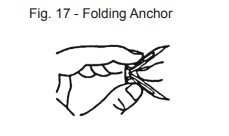
2. Fold wall expansion bracket as shown in (See Fig. 17).
3. Insert wall expansion bracket (wings first) into hole. Tap expansion bracket flush to wall.
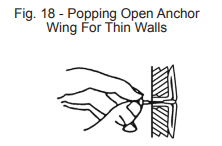
4. For thin walls (1/2 inch or less), insert expansion bracket tool into expansion bracket. Push expansion bracket tool to “pop” open expansion bracket wings (See Fig. 18).
5. Place mounting bracket onto wall. Line up last hole on each end of bracket with expansion bracket.
6. Insert expansion bracket screws (ST4.8*15-16) through wall mounting bracket and into expansion brackets.
7. Tighten expansion bracket screws (ST4.8*15-16) until mounting bracket is firmly fastened to wall.
8. Check that the bracket is secure before mounting heater!
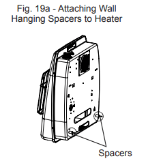
Attaching Wall Hanging Spacers to Heater
WARNING: Failure to properly install the wall hanging spacers may result in property damage, personal injury or even death.
1. Locate spacer mounting holes on the lower right/left sections of the heater back panel.
2. Secure (2) wall hanging spacers to heater back panel using (2) wall hanging spacer screws (M4*25) (See Fig. 19a).
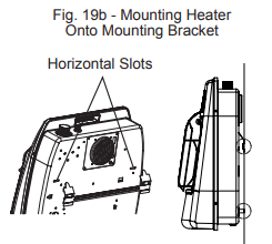
Placing Heater On Mounting Bracket
1. Locate two horizontal slots on back panel of heater.
2. Place heater onto mounting bracket. Slide horizontal slots onto stand-out tabs on mounting bracket. Be sure spacers rest evenly against wall (See Fig. 19b).
CONNECTING TO GAS SUPPLY
Typical Inlet Pipe Diameters
Use 3/8-inch black iron pipe or greater. Installation must include an equipment shutoff valve, union, and plugged 1/8-inch NPT tap. Locate NPT tap within reach for test gauge hook up. NPT tap must be upstream from heater (see Fig. 20).
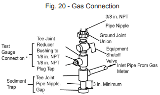
IMPORTANT: Install an equipment shutoff valve in an accessible location. The equipment shutoff valve is for turning on or shutting off the gas to the appliance.
Apply pipe joint sealant lightly to male threads. This will prevent excess sealant from going into pipe. Excess sealant in pipe could result in clogged heater valves.
Install sediment trap in supply line as shown (See Fig. 20). Place sediment trap where it is within reach for cleaning. Place sediment trap where trapped matter is not likely to freeze. A sediment trap traps moisture and contaminants. This keeps them from going into heater controls. If sediment trap is not installed or is installed wrong, heater may not run properly.
CHECKING GAS CONNECTIONS
Pressure Testing Gas Supply Piping System Test Pressures In Excess Of 1/2 PSIG ( 3.5kPa )
The appliance and its appliance main gas valve must be disconnected from the gas supply piping system during any pressure testing of that system at test pressures in excess of ½ psi (3.5 kPa).
Pressure Testing Gas Supply Equal To or less than 1/2 PSIG ( 3.5kPa )
The appliance must be isolated from the gas supply piping system by closing its equipment shut-off valve during any pressure testing of the gas supply piping system at test pressures equal to or less than ½ psi (3.5 kPa).
Leak Testing Heater Gas Internal Connections
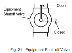
1. Open equipment shutoff valve (See Fig. 21).
2. Make sure control knob of heater is in the OFF position.
3. Open gas supply tank valve (LP systems).
4. Check all joints from equipment shutoff valve to control valve. Apply 50/50 mixture of liquid soap and water to gas joints. If bubbles form, there may be a leak.
5. Light heater (see Operation, page 18). Check all other internal joints for leaks.
6. Turn off heater (see "To Turn Off Gas to Appliance," page 19).
OPERATION
FOR YOUR SAFETY READ BEFORE LIGHTING
A. This appliance has a pilot which must be lighted using the Ignitor. When lighting the pilot, follow these instructions exactly.
B. BEFORE LIGHTING smell all around the appliance area for gas. Be sure to smell next to the floor because some gas is heavier than air and will settle on the floor.
WHAT TO DO IF YOU SMELL GAS
- Do not try to light any appliance.
- Do not touch any electrical switch; do not use any phone in your building.
- Immediately call your gas supplier from a neighbor’s phone. Follow the gas supplier’s instructions.
- If you cannot reach your gas supplier, call the fire department.
C. Use only your hand to push in or turn the gas control knob. Never use tools. If the knob will not push in or turn by hand, don't try to repair it, call a qualified service technician. Forced or attempted repair may result in a fire or explosion.
D. Do not use this appliance if any part has been under water. Immediately call a qualified service technician to inspect the appliance and to replace any part of the control system and any gas control, which has been under water.
LIGHTING INSTRUCTIONS
MANUAL GAS CONTROL
1. STOP! Read the safety information above on this page.
2. Turn off all electric power to the appliance.
3. Push in gas control knob slightly and turn clockwise to OFF  position. (See Fig. 22a)
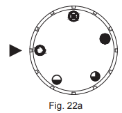
NOTE: Knob cannot be turned from PILOT  to OFF unless knob is pushed in slightly. Do not force.
4. Wait (5) minutes to clear out any gas. Then smell for gas, including near the floor. If you smell gas, STOP! Follow “B” in the safety information above. If you don’t smell gas, go to the next step.
5. Push in gas control knob slightly and turn counterclockwise to the PILOT position. (See Fig. 23a) Depress control knob.
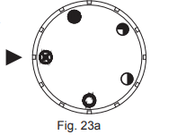
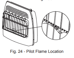
6. With control knob depressed, push down on the ignitor button until the pilot lights. The pilot is visible, centered below the main burner, behind the glass panel. (See Fig. 24 on page 19)
7. Keep control depressed for (30) seconds after pilot lights. Release control knob
Note: If pilot goes out repeat steps 3 through 7. Wait (1) minute before attempting to light pilot again. If after several tries the pilot still goes out, turn the gas control knob clockwise to the "OFF" position and call your service technician or gas supplier. If the control knob does not pop up when released, stop and immediately and call your service technician or gas supplier.
8. Turn on all electric power to the appliance.
9. Turn control knob counter clockwise to desired setting.
THERMOSTAT GAS CONTROL
1. STOP! Read the safety information on the previous page.
2. Turn off all electric power to the appliance.
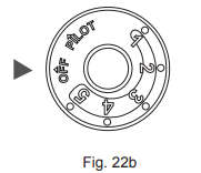
3. Turn control knob clockwise to "OFF" position. (See Fig. 22b)
4. Wait (5) minutes to clear out any gas. Then smell for gas, including near the floor. If you smell gas, STOP! Follow “B” in the safety information above. If you don’t smell gas, go to the next step.
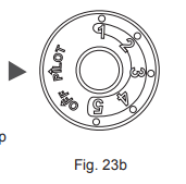
5. Turn knob counterclockwise to the "PILOT" position. (See Fig. 23b) Depress control knob.
6. With control knob depressed, push down on the ignitor button until the pilot lights. The pilot is visible, centered below the main burner, behind the glass panel. (See Fig. 24)
7. Keep control depressed for (30) seconds after pilot lights. Release control knob.
8. Turn on all electric power to the appliance.
9. Turn control knob counter clockwise to desired setting.
TO TURN OFF GAS TO APPLIANCE
1. Turn off all electric power to the appliance if service is to be performed.
2. Push in gas control knob slightly and turn clockwise to "OFF" or position. DO NOT FORCE.
THERMOSTATIC CONTROL OPERATION (SELECT MODELS)
The control knob can be set to any comfort level between "HIGH" (5) and "LOW"(1) (See Fig. 25).The thermostat used on this heater senses the room temperature. At times the room may exceed the set temperature. When this begins to happen, the burner will begin to modulate the BtuH down until the unit meets the desired heat setting and shuts off. When the room temperature drops below the desired heat setting, the burner will cycle back on. The unit may start at a lower BtuH rate if the room is still warm.
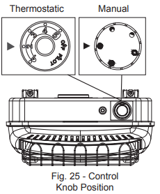
MANUAL CONTROL OPERATION
Manual valves remain burning at the desired setting until manually turned to OFF (See Fig. 25).
INSPECTING BURNERS
Check pilot flame pattern daily when in use and at least yearly by a qualified service agency.
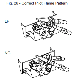
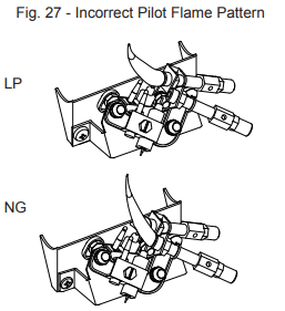
PILOT FLAME PATTERN
Fig. 26 shows a correct pilot flame pattern. Fig. 27 shows an incorrect pilot flame pattern. The incorrect pilot flame is not touching the thermocouple. This will cause the thermocouple to cool, which shuts the heater off. If pilot flame pattern is incorrect:
- turn heater off (see “To Turn Off Gas to Appliance” on page 19)
- see Troubleshooting pages 23 through 26
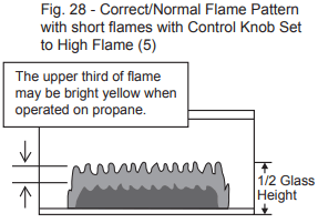
BURNER FLAME PATTERN
Fig. 28 shows a correct burner flame pattern. Fig. 29 shows an incorrect burner flame pattern with lifting, and excessive flame height. If burner flame is incorrect:
- turn heater off (see “To Turn Off Gas to Appliance”, page 19).
- see Troubleshooting, pages 23 through 26.

CARE AND MAINTENANCE
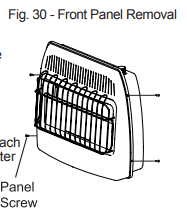
NOTE: Before servicing you will need to remove the front panel of the heater. There are 4 Philips head screws, 2 on the left side and 2 on the right, securing the front panel to the heater (See Fig. 30). Always allow the unit to cool for at least thirty minutes before attempting to remove the front panel.
CLEANING ODS/PILOT AND BURNER
Use a vacuum cleaner, pressurized air, or a small, soft bristled brush to clean burner ports, orifice and primary burner. Look into burner opening and ensure that it is clean.
CLEANING BURNER PILOT AIR INLET HOLE
We recommend that you clean the unit every three months or after 2,500 hours of operation. We also recommend that you keep the burner tube and pilot assembly clean and free of dust and dirt. To clean these parts we recommend using compressed air no greater than 30 PSI. You can use a vacuum cleaner in the blow position. If using compressed air in a can, please follow the directions on the can. If you don't follow directions on the can, you could damage the pilot assembly.
1. Shut off the unit, including the pilot. Allow the unit to cool for at least thirty minutes.
2. Remove 4 screws - 2 screws on each side of the front panel.
3. Pull front panel forward.
4. Blow air through the ports/slots and holes in the burner. Also clean the pilot assembly. A yellow tip on the pilot flame indicates dust and dirt in the pilot assembly. There is a small pilot air inlet hole about two inches from where the pilot flame comes out of the pilot assembly (see Fig. 26 & 27 on page 20). With the unit off, lightly blow air through the air inlet hole. You may blow through a drinking straw if air is not available.
5. Replace front panel when completed, using the screws removed.
CLEANING GLASS
Use mild soap and water. Avoid using abrasive cleaners which can scratch the glass. The tempered glass installed on this product contains a “Low E” coating on the interior surface. If the glass is removed, you must ensure the “Low E” coated side is installed on the interior side, facing the burner assembly.
CLEANING CABINET AIR PASSAGEWAYS
Use a vacuum cleaner or pressurized air to clean.
CLEANING FAN (Select Models)
Carefully use a vacuum cleaner or compressed air to keep fan compartment and blades free of dust and debris.
CLEANING EXTERIOR
Use a soft cloth dampened with a mild soap and water mixture. Wipe the cabinet to remove dust.
TROUBLESHOOTING
| PROBLEM |
POSSIBLE CAUSE |
CORRECTIVE ACTION |
| When Ignitor Module is pressed in, there is no spark at ODS/pilot. |
1. Ignitor electrode is positioned wrong.
2. Ignitor electrode is broken.
3. Ignitor electrode is not connected to ignitor cable.
4. Ignitor cable is pinched or wet.
5. Damaged ignitor cable.
6. Bad ignitor module or ignition module.
|
1. Replace ODS.
2. Replace ODS.
3. Replace ignitor cable
4. Free ignitor cable if pinched by any metal or tubing. Keep ignitor cable dry.
5. Replace ignitor cable.
6. Replace ignitor module or ignition module.
|
| Unit shuts off after running a few minutes. |
1. Gas supply is turned off or equipment shutoff valve is closed.
2. Control knob not fully pressed in while pressing ignitor module.
3. Air in gas lines when installed.
4. ODS / pilot is clogged.
5. Gas regulator setting is not correct.
6. Control knob not in PILOT position.
7. Depleted gas supply (propane).
8. Incorrect gas setting regulator or selector valve.
|
1. Turn on gas supply or open equipment shutoff valve.
2. Fully press in control knob while pressing Piezo Ignitor.
3. Continue holding down control knob. Repeat igniting operation until air is removed.
4. Clean ODS/pilot (see Care and Maintenance, page 21) or replace ODS/ pilot assembly.
5. Replace gas regulator.
6. Turn control knob to PILOT position.
7. Contact local propane/LP gas company.
8. Call qualified service technician.
|
| ODS/pilot lights but flame goes out when control knob is released. |
1. Control knob is not fully pressed in.
2. Control knob is not pressed in long enough.
3. Equipment shutoff valve is not fully open.
4. Thermocouple connection is loose.
5. Thermocouple damaged.
6. Control valve damaged.
7. Wrong gas setting.
|
1. Press in control knob fully.
2. After ODS/pilot lights, keep control knob pressed in 30-60 seconds.
3. Fully open equipment shutoff valve.
4. Hand tighten until snug, and then tighten ¼ turn more.
5. Replace thermocouple.
6. Contact customer service.
7. Correct gas selection.
|
| Burner(s) does not light afterODS/pilot is lit. |
1. Thermostat setting too low.
2. Burner orifice is clogged.
3. Burner orifice diameter is too small.
4. Inlet gas pressure is too low.
|
1. Turn thermostat knob to a higher setting.
2. Clean burner orifice (see Care and Maintenance, page 21) or contact customer service.
3. Contact customer service.
4. Contact your gas supplier.
|
| Delayed ignition of burner(s). |
1. Manifold pressure is too low.
2. Burner orifice is clogged.
|
1. Contact your gas supplier.
2. Clean burner (see Care and Maintenance, page 21) or contact customer service.
|
| Burner backfiring during combustion. |
1. Burner orifice is clogged or damaged.
2. Burner is damaged.
3. Gas regulator is damaged.
|
1. Clean burner orifice (see Care and Maintenance, page 21 or contact customer service.
2. Contact dealer or customer service.
3. Replace gas regulator.
|
| High yellow flame during burner combustion |
1. Not enough air.
2. Gas regulator is defective.
3. Wrong gas type selected.
|
1. Check burner for dirt and debris. If found, clean burner (see Care and Maintenance, page 21).
2. Replace gas regulator.
3. See Gas Selection, page 11.
|
| Gas odor during combustion. |
1. Foreign matter between control valve and burner.
2. Gas leak. (See Warning Statement at top of page 23).
|
1. Take apart gas tubing and remove foreign matter
2. Locate and correct all leaks (see “Checking Gas Connections,” page 17).
|
| Heater produces a clicking/ticking noise just after burner is lit or shut off. |
1. Metal is expanding while heating or contracting while cooling. |
1. This is common with most heaters. If noise is excessive, contact qualified service technician. |
| White powder residue forming within burner box or on adjacent walls or furniture. |
1. When heated, the vapors from furniture polish, wax, carpet cleaners, etc., turn into white powder residue. |
1. Turn heater off when using furniture polish, wax, carpet cleaner or similar products. |
| Heater produces unwanted odors. |
1. Heater is burning vapors from paint, hair spray, glues, etc. See IMPORTANT statement, page 22.
2. Gas leak. See Warning Statement, page 23.
3. Low fuel supply.
|
1. Ventilate room. Stop using odor causing products while heater is running.
2. Locate and correct all leaks (see “Checking Gas Connections,” page 17).
3. Refill supply tank (Propane /LP models).
|
| Heater shuts off in use (ODS operates). |
1. Not enough fresh air is available.
2. Low line pressure.
3. ODS/pilot is partially clogged.
|
1. Open window and/or door for ventilation.
2. Contact local gas supplier.
3. Clean ODS/pilot (see Care and Maintenance, page 22).
|
| Gas odor exists even when control knob is in OFF position. |
1. Gas leak. See Warning Statement at top of page 22.
2. Control valve is defective.
|
1. Locate and correct all leaks (see “Checking Gas Connections”, page 17).
2. Contact customer service.
|
| Moisture/ condensation noticed on windows. |
1. Not enough combustion/ ventilation air. |
1. Refer to “Air for Combustion and Ventilation” requirements, page 7. |
| Slight smoke or odor during initial operation |
1. Residues from manufacturing process. |
1. Problem will stop after a few hours of operation. |
| Heater produces a whistling noise when burner is lit. |
1. Turning control knob to high (5) position when burner is cold.
2. Air in gas line.
3. Air passageways on heater are blocked.
4. Dirty or partially clogged burner orifice.
|
1. Turn control knob to low (1) position and let warm up for a minute.
2. Operate burner until air is removed from line. Have gas line checked by local propane/LP gas company.
3. Observe minimum installation clearances (Fig. 3, page 10)
4. Clean burner (see Care and Maintenance, page 22) or contact customer service.
|
| Fan is not spinning. (Select models) |
1. There is no power to the fan.
2. Fan is set to "AUTO".
3. Fan motor is bad.
|
1. Verify fan is plugged in and set to "MAN" or "AUTO".
2. Allow 5-10 minutes for fan to engage.
3. Replace fan.
|
| Fan is making a loud noise. (Select models) |
1. Fan housing or blades are dirty.
2. Fan rotation is blocked.
3. Defective fan.
|
1. See "Cleaning Fan", page 22.
2. Verify wiring is not in fan path.
3. Replace fan.
|
PRODUCT SPECIFICATIONS