Installation Instructions
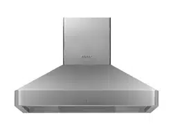
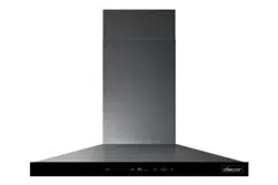
Modernist Range Hood
DHD30M967WM, DHD36M976WM, DHD48M987WM,
DHD30M967WS, DHD36M976WS, DHD48M987WS
Part No. 110452 RevB

English2
Contents
Contents
Before you begin... 3
Important 3
Customer-service information 4
If You Need Help... 4
Important safety instructions 5
Related equipment safety 5
Important Information about safety instructions 5
Installation requirements 9
Checklist 9
Prepare to install hood 10
Installation Planning 12
Hood Dimension 12
Installation instructions 18
Meeting Electrical Codes 18
Preparation and Setup 19
Installing the Electrical Source 19
Meeting Installation Requirements 20
Planning the Ductwork 21
Planning the Mounting Location 24
Marking the Centerlines 25
Installing the Support Brackets 26
Blower Rotation (Rear Exhaust) 27
Remove and Replace parts 28
Assembling the Filters 30
Using the Dual-to-Single Transition Kit #AHT10 31
Hanging the Hood 33
Hardwiring the Hood 34
Inserting Light Bulbs 37
Attaching the Dacor Badge 37
Verifying the Setup 38
Wiring Diagram 40

English 3
Before you begin...
Before you begin...
Important
Installer
• In the interest of safety and to minimize
problems, read these installation
instructions completely and carefully
before you begin the installation
process.
• Leave these installation instructions
with the customer.
Customer
• Keep these installation instructions for
future reference and the local electrical
inspector’s use.

English4
Customer-service information
Customer-service information
If You Need Help...
…with questions or installation problems, contact your Dacor® dealer or the Dacor
Customer-Service Team. For under-warranty repairs to Dacor appliances, call the Dacor
Distinctive Service line. When you call, be prepared with the appliance’s model and serial
number. (See the appliance’s data plate.)
Dacor Modernist Service (repairs under warranty only)
Phone: (800) 793-0093 ex. 2822 (U.S.A. and Canada)
Monday — Friday 6:00 a.m. to 4:00 p.m. Pacific Time
Dacor Customer Service
Phone: (800) 793-0093 ex. 2813 (U.S.A. and Canada)
Monday — Friday 6:00 a.m. to 5:00 p.m. Pacific Time
Web site: www.dacor.com
Appliance Data Plate
This label contains the model and serial numbers, and electrical requirements, and is inside
the hood above the filters on the chassis’ back wall.
(Remove the filters to view the data
plate.)
All specifications are subject to change without notice. Dacor assumes no liability for
changes to specifications.
© 2017 Dacor, all rights reserved.
English 5
Important safety instructions
Important safety instructions
Related equipment safety
Remove all tape and packaging before using the appliance. Dispose of the packaging after
unpacking the appliance. Never allow children to play with packaging material.
Never modify or alter the construction of the appliance. For example, do not remove
panels, wire covers or screws.
DANGER
ELECTRICAL SHOCK HAZARD
To avoid risk of electrical shock, personal injury or death; verify your appliance has
been properly grounded in accordance with local codes or in absence of codes, with the
National Electrical Code (NEC). ANSI/NFPA 70-latest edition.
WARNING
MOVING HAZARD
To avoid risk of severe personal injury; this appliance requires two or more people while
handling and moving. Use of appliance moving devices is recommended.
Important Information about safety instructions
• The Important Safety Instructions and warnings in these instructions are not meant to
cover all possible problems and conditions that can occur. Use common sense and
caution when installing, maintaining or operating this or any other appliance.
• Always contact the Dacor Customer Service Team about problems and conditions that
you do not understand.

Important safety instructions
English6
Important safety instructions
To reduce risk of fire, electric shock, serious injury or death when using your appliance,
follow basic precautions, including the following:
WARNING
• Do not store o
r use combustible or explosive substances (e.g., gas, alcohol, paint
thinner, aerosol
cans) on nearby countertops or in adjacent cabinetry.
WARNING
TO AVOID THE POSSIBILITY OF FIRE, ELECTRIC SHOCK, PERSONAL INJURY, OR DEATH:
• Follow the directions in this manual exactly
• Use the hood only as intended by the manufacturer. If you have questions, contact the
manufacturer.
• Before servicing/cleaning the hood, switch power off at service panel, and lock access
to the panel to prevent power from being switched on accidentally. If access cannot be
locked, securely fasten a prominent warning device, such as a tag, to the panel.
• Installation work and electrical wiring must be done by qualified person(s) according to
applicable codes and standards, including fire-rated construction.
• Sufficient air is needed for proper combustion and exhaustion of cooktop gases to
prevent backdraft; follow the cooktop manufacturer’s guideline and safety standards
such as those published by the National Fire Protection Assn (NFPA), and the American
Society for Heating, Refrigeration and Air Conditioning Engineers (ASHRAE), and the
local code authorities.
• When cutting or drilling into a
wall or ceiling, take care not to damage electrical wiring
and other hidden utilities.
• Ducted fans must always be vented to the outdoors.
WARNING
• Use the hood only as outlined in this manual. Do NOT use the hood to vent hazardous/
explosive materials or vapors. If you have questions, contact Dacor (contact info on Pg.
4).
• If you receive a damaged product, immediately contact your dealer/builder. Do not
install/use a damaged hood.
• Verify that the hood was properly installed and grounded by a qualified installer
according to procedures in this guide. Have the installer show you the fuse or junction
box so you can turn the power ON/OFF as needed.
• Install this appliance according to these instructions and the requirements specified by
the manufacturer of the cooktop or range. Improper installation, adjustment, alteration,
service, or maintenance can cause serious personal injury or property damage.

English 7
Important safety instructions
• Do not install/repair/replace any part of the range hood unless specifically
recommended by the procedures in this guide. A qualified service technician should
perform all other service. Contact the nearest Dacor authorized service representative
at (800) 793-0093, or at www.dacor.com for examination, repair or adjustment.
• Do not use an extension cord or adapter plug with this appliance.
•
To avoid risk of electric shock:
- Before service is performed, switch power off at the fuse/junction box, and lock the
electrical-panel door so power cannot be switched on. If the electrical panel cannot
be locked, securely fasten a prominent warning device (e.g., tag) to the panel.
- Before cleaning the hood, turn off the main power switch.
• Read the Use and Care Manual completely before using the appliance. Clean the
appliance only as instructed in the Use and Care Manual. Use only the cleaners
specified.
• Do not tamper with the controls.
WARNING
• Never let the filters become blocked/clogged, or foreign objects (e.g., cigarettes,
napkins) be sucked into the hood.
• To avoid a fire hazard:
- If the appliance is by a window, do not use window coverings that could blow over
the cooking surface and hood.
• Use only metal ducting.
• Always run the hood fans when using your range/cooktop.
• Never let children:
- alone in the vicinity of an operating range/cooktop
- sit/stand on/play with your range/cooktop/hood; or store items of interest to
children above/around these appliances.
- play with packaging materials; plastic bags can cause suffocation.
• The minimum vertical distance between the cooking surface and the bottom-most part
of the hood must be at least 30” (76.2 cm). Consult the instructions in this manual for
the minimum vertical distance in your specific case.
• Do not attempt to use this appliance during a continuous power outage.
• To reduce risk of a grease fire:
- always turn the hood ON if cooking at high heat or when flambéing food (e.g.,
Crepes Suzette, Cherries Jubilee, Peppercorn Beef Flambé
- clean ventilating fans frequently; do not let grease accumulate on the filter or
other hood components

Important safety instructions
English8
Important safety instructions
WARNING
• T
O REDUCE RISK OF
PERSONAL INJURY FROM A GREASE FIRE:
-
CAREFULLY SMOTHER FLAMES with a close-fitting lid, cookie sheet, or metal tray,
then turn off the burner. If the flames do not die immediately, EVACUATE, THEN
CALL THE FIRE DEPARTMENT.
-
NEVER PICK UP A FLAMING PAN.
- DO NOT try to extinguish flames with water or wet dish cloths/towels; a violent
steam explosion may result.
• (FOR GREASE FIRES) USE A FIRE EXTINGUISHER ONLY IF:
- you have a Class ABC extinguisher and know how to operate it
- the fire is small and contained in its area of origin
- the fire department is being called
- you can fight the fire with your back to an exit.

English 9
Installation requirements
Installation requirements
Checklist
Use this checklist to verify that you have completed each step of the installation process.
This can help you avoid mistakes.
WARNING
• To ensure a safe, correct installation, this checklist should be completed by the
installer.
• The homeowner shall ensure the hood’s proper installation.
The hood is properly attached to the wall as instructed beginning on Pg. 24.
Ducting is fully installed; joints are secured with sheet-metal screws and wrapped
with foil tape. See Pg. 21-23.
The hood is wired/grounded as instructed and per all applicable electric codes. See
Pgs. 18-19.
Filters are assembled as instructed on Pg. 30.
The setup was verified.
Any problems were noted on the warranty card or during the online warranty
activation. The warranty card was completed and mailed, or the warranty activated
online.
English10
Installation requirements
Installation requirements
Prepare to install the hood
Have these tools and hardware within reach before you start the installation.
Hood Installation
Phillips screwdriver Level
Flathead screwdriver Junction box
Pencil/marking tool Jigsaw
Wire connector caps 8” Ducting
Wire stripper Foil tape
Drill, bits Sheet-metal screws
Dual-to-Single Vent Transition Kit (option)
Dacor Kit #AHT10 (Model DHD48 only) Sheet-metal screws
10” Ducts, ducting material Foil tape
Drill, bits
Blower Rotation (option)
Phillips screwdriver 5/16” Nut driver
English 11
Installation requirements
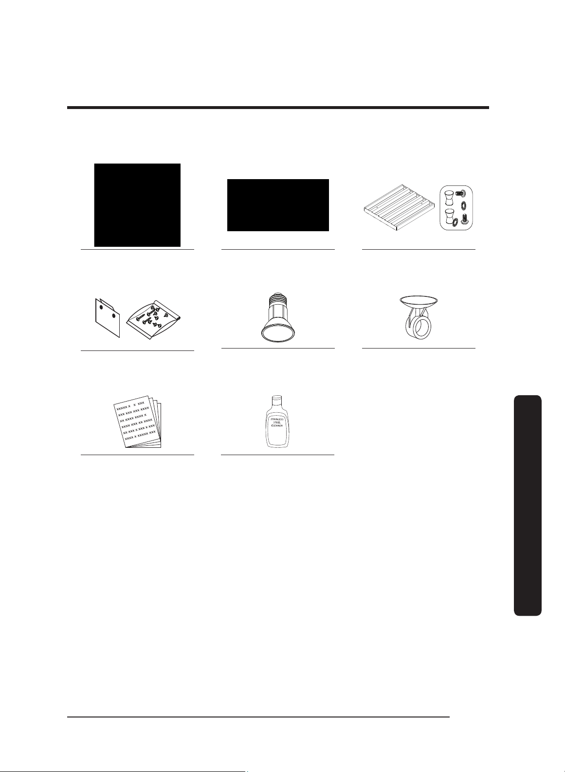
Parts List
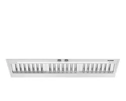
Hood (1)
(models vary in size)
Grease channel (1) Baffle-style filter*
48” (4), 36” (3), 30” (2)
Holding brackets, Hardware
(2)
Dimmable LED light bulbs
48” (4), 36” (3), 30” (2)
Light-replacement tool (1)
Product literature** (2)
Dacor cleaning cream (1)
stainless steel units only
* Ready-to-assemble kit
** Installation instruction, User manual.
English12
Installation requirements
Installation requirements
Installation Planning
• A qualified technician must complete the installation of this built-in appliance. Proper
installation is the customer's responsibility.
• Carefully check the location where the Hood is to be installed.
The Hood should be placed for convenient access. Make certain that electrical power
can be provided in the selected location.
• Plan the installation so that all minimum clearances are met or exceeded. Dimensions
shown provide minimum clearances, unless otherwise noted. Be certain that proper
clearance is provided for the Hood when it is in the open position.
• The specified minimum cabinet depth and width must be provided.
• Make certain that you have everything necessary to ensure a proper installation before
proceeding.
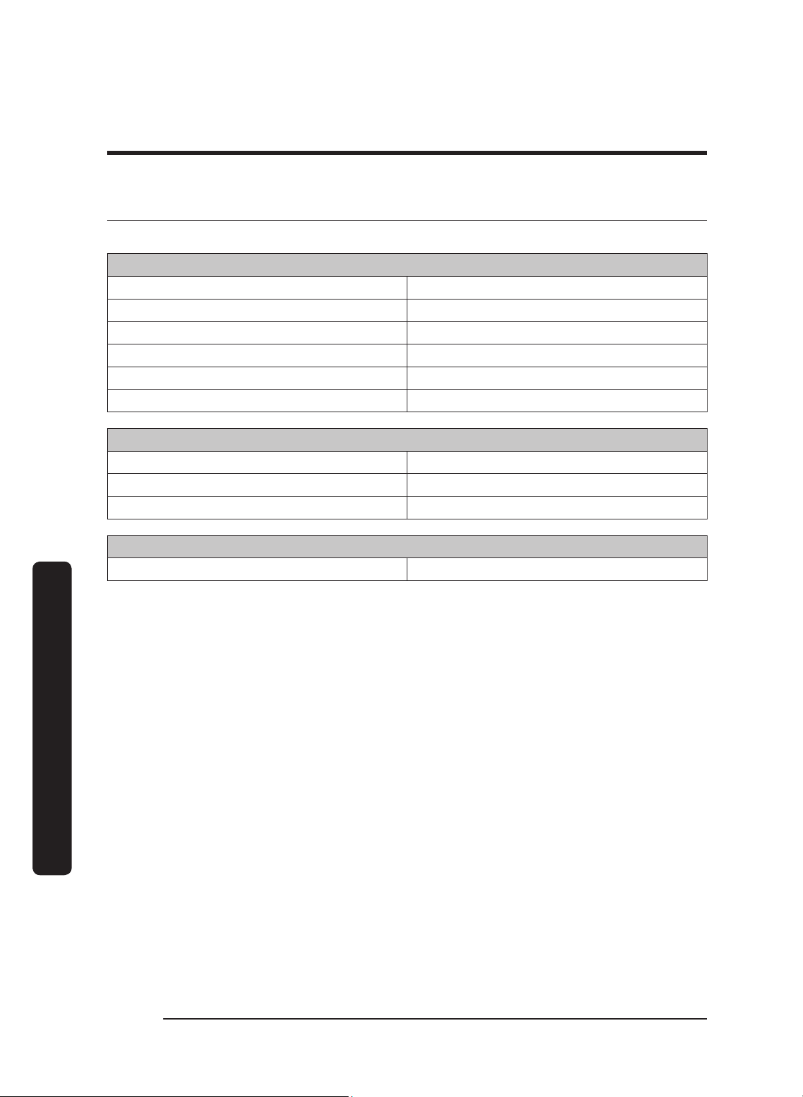
Hood Dimension
General Specifications
All Models: DHD30/36/48
Features Description
Blower Speeds Four (4)
Filters Baffle style, dishwasher safe
Exhaust(s) 8” duct diameter
Total Connect Load
30”, 36”: 120V, 60 Hz, 15 Amp (actual load 3.3 Amp, 6
Amp initial surge)
48”: 120V, 60 Hz, 15 Amp (actual load 6.1 Amp, 12 Amp
initial surge)
Lights
Dimmable LED: PAR16 E26/27; 120V, 7.5W (75W Max.
other bulbs)
English 13
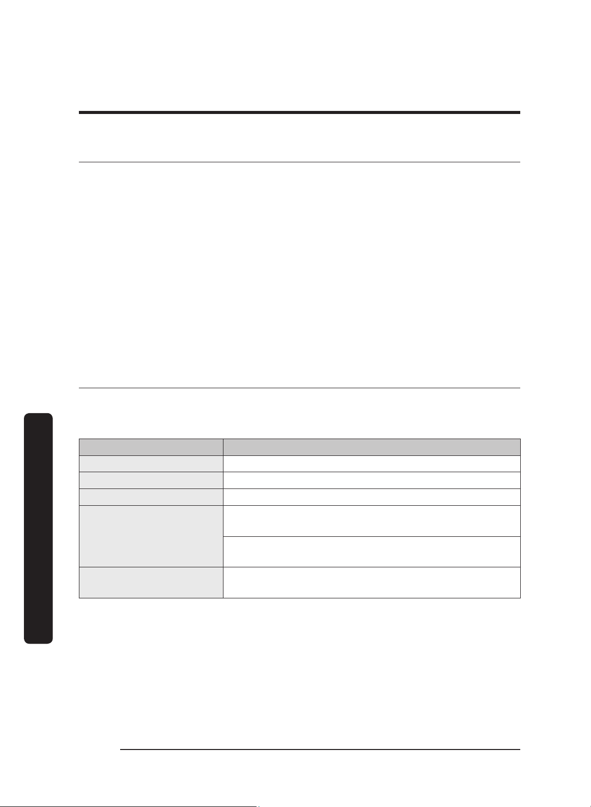
Installation requirements
Individual Models: DHD30/36/48
Components 48” 36” 30”
Lights
4 3 2
Filters
Blowers
2 1 1
Exhaust Vents
Blower Rating 1200 CFM 600 CFM 600 CFM
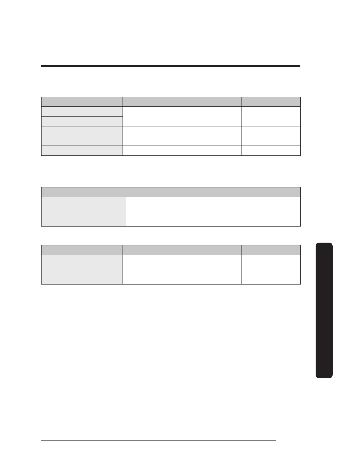
Weight Specifications
Individual Models: DHD30/36/48
Model Weight
30 53 lbs (24 kg)
36 57 lbs (26 kg)
48 77 lbs (35 kg)
Individual Models: DHD30/36/48
Model Top Vent Rear Vent Rotatable Fan
30 x x x
36 x x x
48 x x x
English14
Installation requirements
Installation requirements
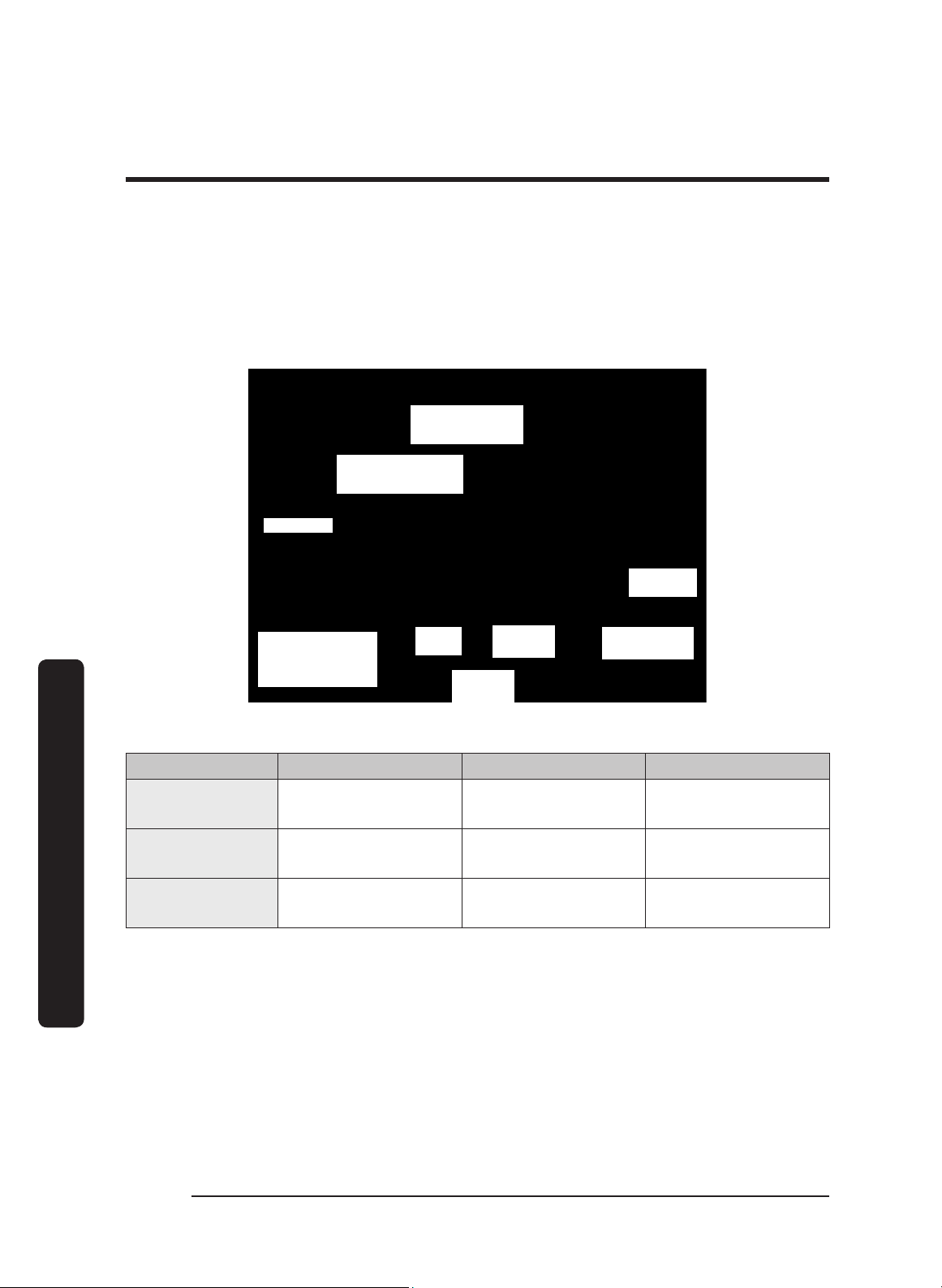
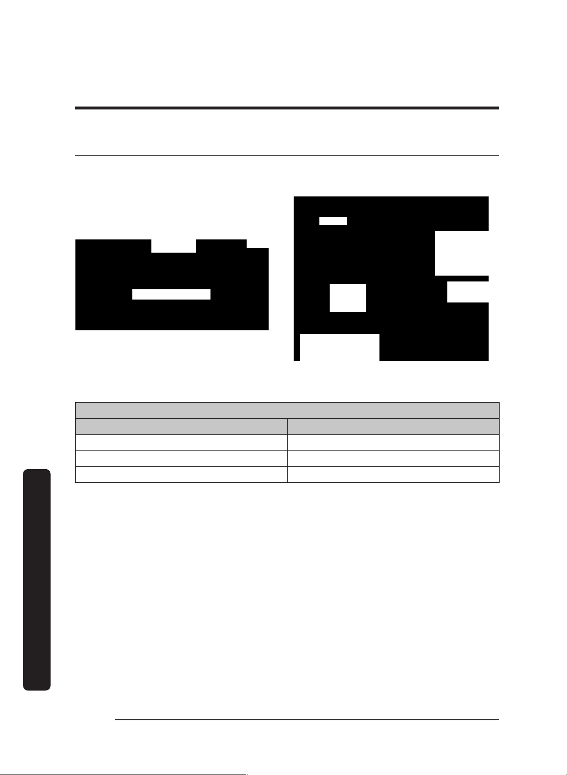
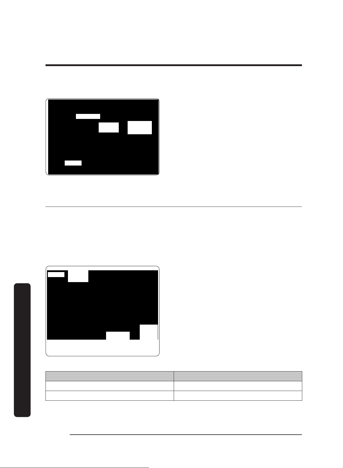
Electrical/Ductwork Connections
Connect electrical wires and ductwork through the top or rear of the hood. Before
installing the hood, mark the access holes according to the diagrams below.
(Tolerances: +1/16” -0”, unless otherwise stated.)
Top Connections: All models
Dual-Exhaust
Standard 8" duct
Single-Exhaust
Standard 8" duct
*See table
5 3/4 in.
(14.6 cm)
Hood back
(against wall)
Hood
C/L
9 7/8 in.
(25.1 cm)
19 3/4 in.
(50.2 cm)
(2) Electrical-
Access Holes
7/8 in. (5.1 cm) dia.
Dimensions: Top Electrical Access Holes (DHD 30/36/48)
Model A B C
48
1 1/2”
(3.81 cm)
5”
(12.7 cm)
3”
(7.62 cm)
36
1 1/2”
(3.81 cm)
4 1/2”
(11.43 cm)
3”
(7.62 cm)
30
1 1/2”
(3.81 cm)
5 1/2”
(13.97 cm)
3”
(7.62 cm)
English 15
Installation requirements
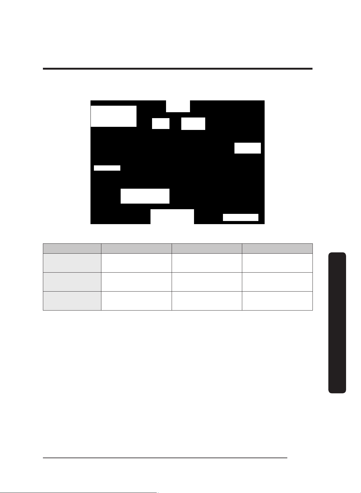
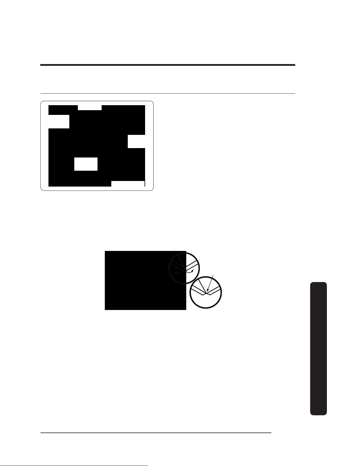
Rear Connections: All models
Single-Exhaust
Standard 8" duct
Dual-Exhaust
Standard 8" duct
Hood bottom
(2) Electrical-
Access Holes
7/8 in. (5.1 cm) dia.
19 3/4 in.
(50.2 cm)
Hood
C/L
9 7/8 in.
(25.1 cm)
5 3/4 in.
(14.6 cm)
*See table
Dimensions: Rear Electrical Access Holes (DHD 30/36/48)
Model A B C
48
1”
(2.54 cm)
5”
(12.7 cm)
3”
(7.62 cm)
36
1”
(2.54 cm)
4 1/2”
(11.43 cm)
3”
(7.62 cm)
30
1”
(2.54 cm)
5 1/2”
(13.97 cm)
3”
(7.62 cm)
English16
Installation requirements
Installation requirements
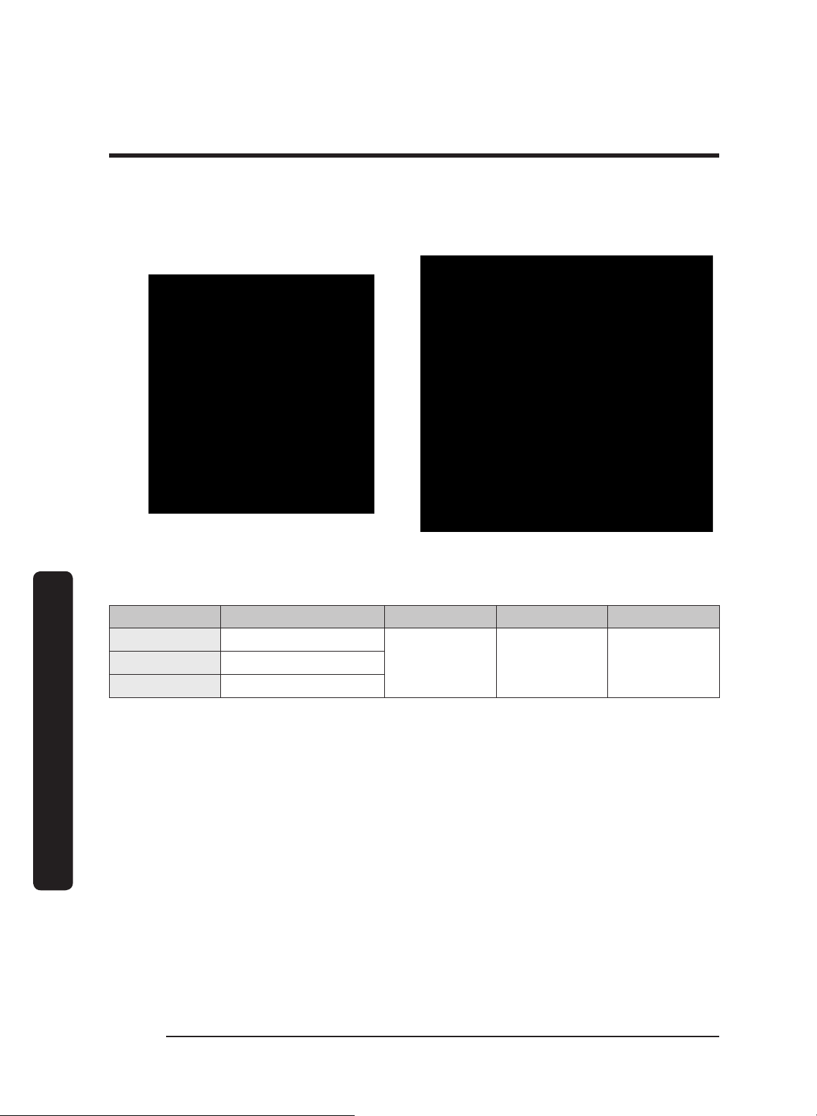
Dimensions (Hood)
Tolerances: +1/16” -0” unless otherwise stated.
Single Blower DHD30/36 Series Dual Blower DHD48 Series
DHD Hood Dimensions
Model A B C D
30 29 7/8” (75.9 cm)
24”
(61 cm)
18”
(45.7 cm)
12”
(30.5 cm)
36 35 7/8” (91.1 cm)
48 47 7/8” (121.6 cm)
English 17
Installation requirements
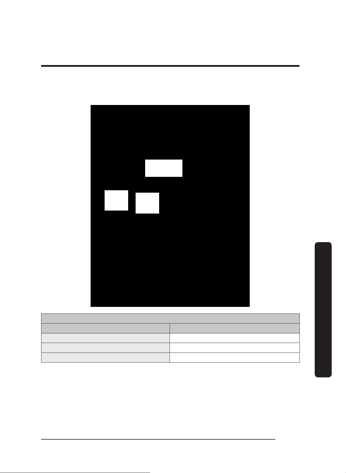
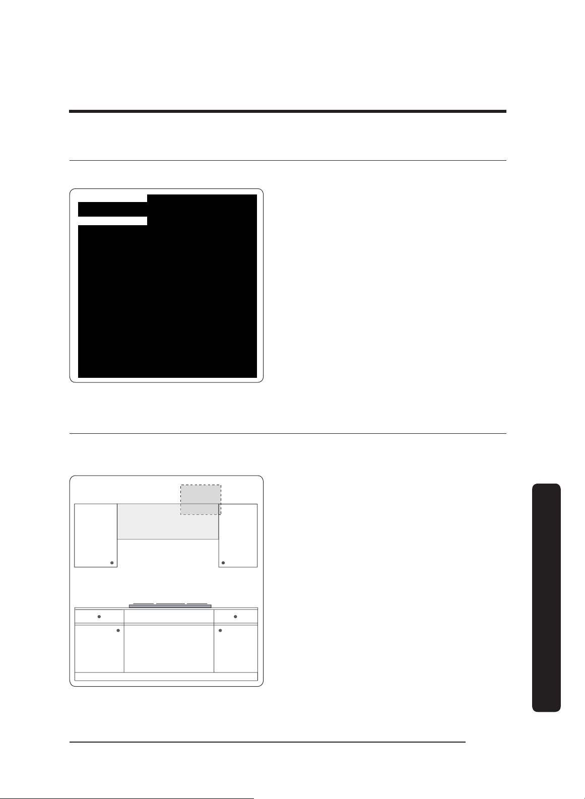
Cabinet-Layout Dimensions
All tolerances: +1/16” -0”, unless otherwise stated.
Electrical access
(top and back of
hood)
* hood
bottom to
cooking
surface
30" min.
(76.2 cm)
Min. Width of E (Upper-Cabinet Cutout, Appliance Width)
Model DHD E
30 30” (76.2 cm)
36 36” (91.5 cm)
48 48” (121.9 cm)

English18
Installation instructions
Installation instructions
Meeting Electrical Codes
• The owner shall verify that all electrical requirements are met by the qualified
electrician servicing this appliance.
• The electrical installation (incl. minimum supply-wire size and grounding) must comply
with the National Electric code ANSI/NFPA (or latest revision), and local codes. Obtain a
copy of the ANSI/NFPA standard from:
- National Fire Protection Association
1 Batterymarch Park
Quincy, Massachusetts 02269-9101
• The ground terminal on the hood must be connected to a grounded, metallic,
permanent wiring system, or a grounding conductor installed by a licensed electrician.
• Do not ground the appliance or appliance wiring to a gas pipeline or to the neutral
(white) power supply wire.
• Do not install a fuse in the neutral or ground circuit.
• Connect the hood directly to an electrical junction box. Hard-wire the hood per local
code directly to a dedicated, three-wire-grounded, single-phase circuit rated at 120 Vac
60 Hz, 15 Amp.
WARNING
Electrical Shock Hazard
Ensure a licensed electrician installs the electrical service to the range hood.
English 19
Installation instructions
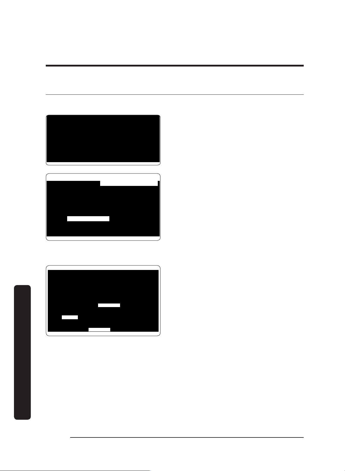
Preparation and Setup
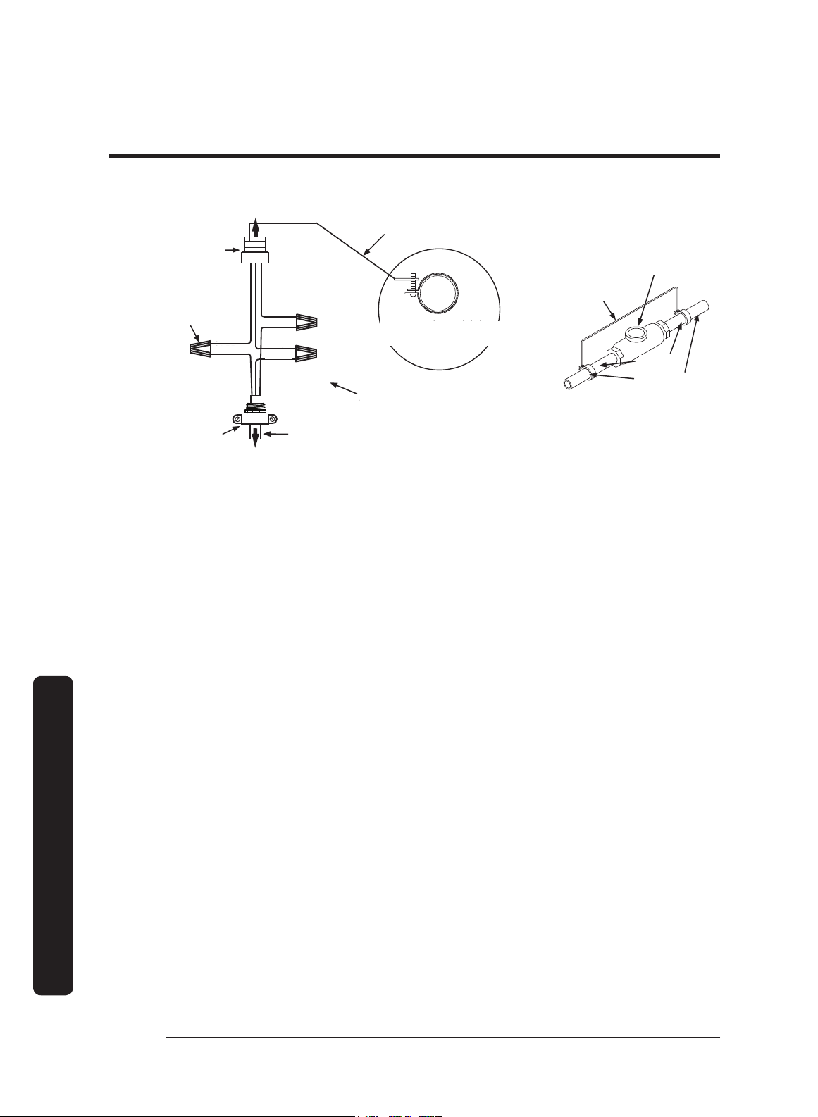
This diagram shows the top and rear locations for wire access into the hood.
Top Access
Rear Access
See Wiring Diagrams at the end of this
document.
Installing the Electrical Source
In compliance with local codes, install an electrical junction box near the hood’s wiring
access holes.
Hood
Suggested Junction
Box Area
1. In the cabinet or wall, drill 7/8” holes
through which to pass the electrical
wiring.
2. See the last pages of this guide for
wiring diagrams.

English20
Installation instructions
Installation instructions
Meeting Installation Requirements
• The hood must be at least as wide as the cooktop.
• All dimensions must meet or exceed specified minimums.
• Dimensions given are minimum clearances unless otherwise noted.
• All contact surfaces between the hood and cabinetry/walls must be sturdy, solid, and
at right angles.
• Install the hood so it can be removed for service.
• WARNING
• Follow local codes during planning/installation. Contact the local building department
for details. Use only code-approved ductwork.
•
To reduce risk of injury from reaching over a hot appliance, do not place cabinets
directly over the range.
IMPORTANT: See the diagram on pg. 17 for the minimum installed distance from hood
to cooktop surface. This distance depends on the range or cooktop in use. Check the
manufacturer's specifications for the cooktop or range.
English 21
Installation instructions
Planning the Ductwork
WARNING
• To prevent combustion by-products, smoke, or odors from entering the home, and to
improve efficiency, tape all duct joints securely.
• Range hoods may impede proper flow of smoke and combustion gases from furnaces,
gas water heaters, and fireplaces. To avoid drawing lethal gases into the home, follow
the manufacturer’s directions for these devices and NFPA/ASHRAE recommendations.
• Failure to install a remote blower or proper ductwork may cause a backdraft and
insufficient venting of smoke/fumes.
• DO NOT add an in-line or external blower to lengthen the duct. Even small differences
between blower air-flow rates can greatly reduce the hood’s air draw.
CAUTION
To reduce risk of fire and to properly exhaust air, duct air to the outdoors only (not into
walls, a
ttics, crawlspaces, or garages).
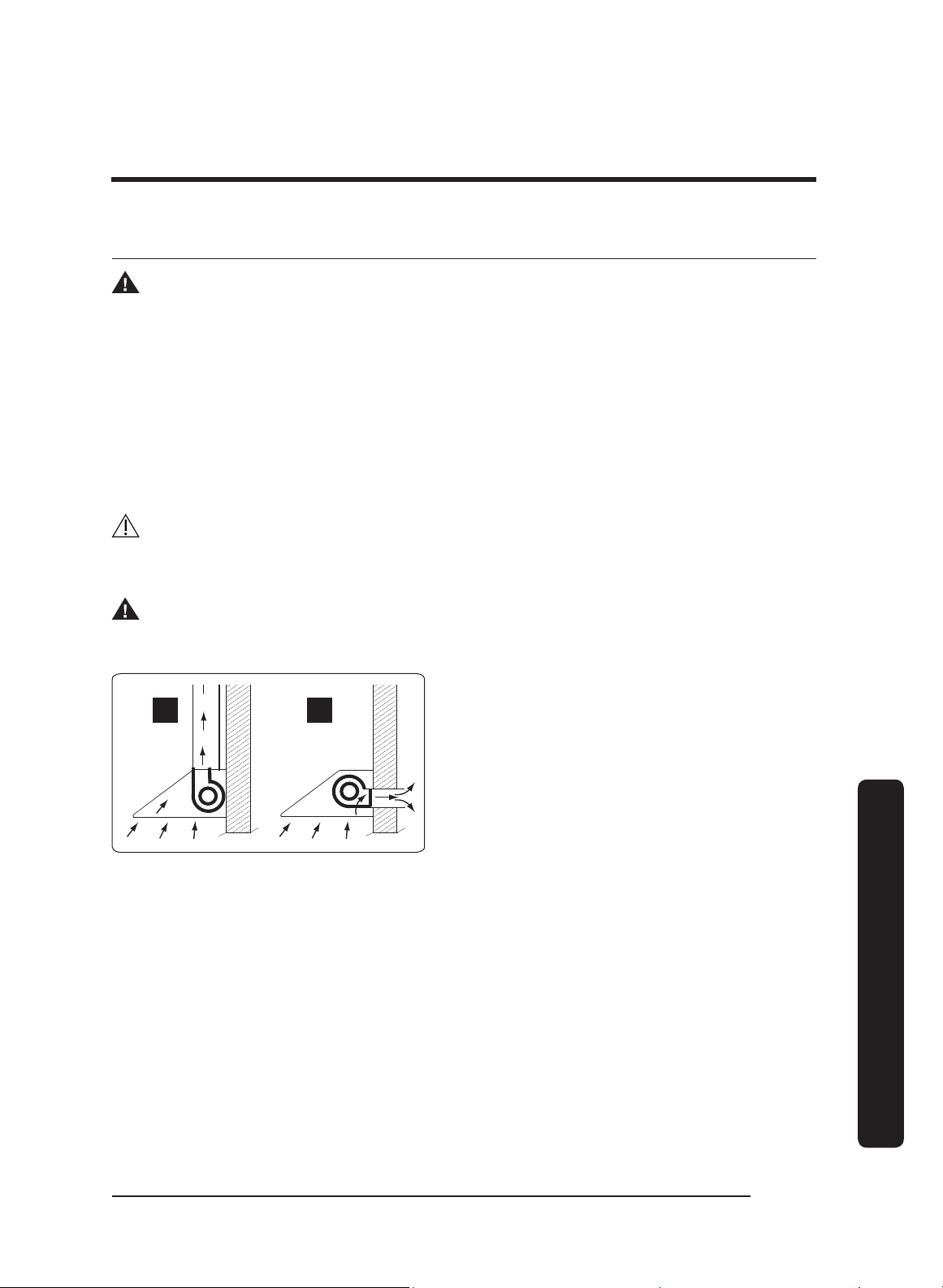
WARNING
During duct installation, ensure the damper flaps on top of the hood can open freely.
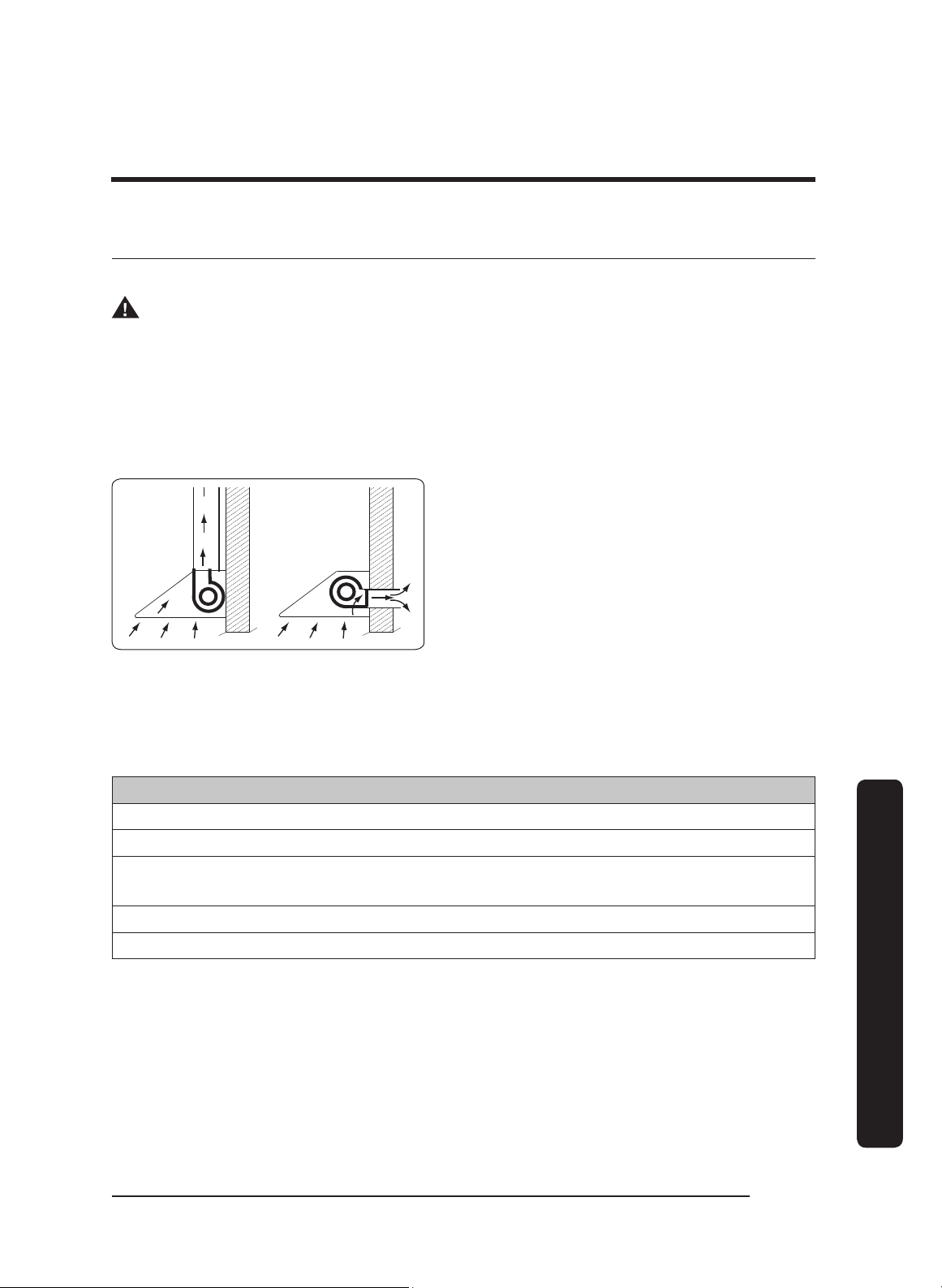
A B
• Building codes may require makeup
air systems to be used with ventilation
systems that move air at greater than
the specified rate (CFM), which rate
depends on locale. In designing the
system, consult an HVAC specialist for
local requirements and to ensure best
performance.
• All ductwork material (incl. screws and foil tape) must be purchased by the customer.
• Ductwork must not interfere with floor joists or wall studs.
• On dual-exhaust models, the two 8” exhausts may be merged into one 10” duct using
Dacor T
ransition Kit AHT10.
• Fasten all joints with sheet-metal screws, and seal with certified duct/foil tape.
• Typically, the blower vents through the hood top (A, above); however, the blower can
be rotated to vent through the rear (B, above). When planning ductwork, always find
the shortest, most direct route to the outside.
English22
Installation instructions
Installation instructions
Duct-Length Calculation Table
The type of duct determines the hood’s maximum straight duct length.
To determine your maximum length, start with the duct run’s total max. length, then
subtract all of the ductwork equivalent lengths. (See the chart.)
Duct Type Max. Duct Run
8-in. Round 60 feet
10-in. Round
50 feet
3 1/4-in x 10-in Rectangular
Ductwork Equivalent Lengths
For each new elbow and transition, you must subtract “equivalent lengths” from your total
maximum duct run length to compensate for wind resistance.
Piece Subtract
8” 90° Elbow 7 feet
8” 45° Elbow 3 feet
10” 90° Elbow 5 feet
10” 45° Elbow 2 feet
3” x 10” to Round 90° Transition 25 feet
3 1/4” x 10” to 8”/10” Round Transition 4 feet
Wall Cap w/Damper
*
Roof Cap
*Equivalent lengths of roof and wall caps vary with model and configuration.

English 23
Installation instructions
Ductwork Tips
• Try to minimize transitions/turns/sharp angles (e.g., two staggered 45° angles are
better than one sharp 90° angle).
• Keep turns as far away from the hood exhaust as possible; keep as much space
between bends as possible.
• For best performance, use round instead of rectangular ducting, especially when
elbows are needed.
• If multiple elbows are used, try to keep at least 24 in. of straight duct between each
elbow.
• Avoid using “S” or back-to-back adjacent elbows.
• In extremely cold-weather regions, use thermal breaks (i.e., short sections of non-
metallic duct) to avoid indoor heat loss. Put the break as close to the outside pass-
through point as possible.
• Do not use flexible metal ducting, or ductwork smaller than what the tables advise.
• The hood exhaust connects to an 8” round duct. You can increase the duct size over the
duct run if desired.
• To prevent backdraft, never decrease the duct size over the run. If existing ductwork is
less than 8 inches in diameter, replace it with 8” ductwork.
• Join ducting with sheet-metal screws, then seal with certified duct/foil tape. Never join
ducting with tape only.
• Support the weight of the ducting with sheet-metal screws as needed.
• To avoid backdraft, a damper at the duct outlet may be required.
WARNING
• Electricity to the range hood should be installed only by a licensed electrician.
• Observe all local codes during site preparation and installation. Contact your local
building department for details.
• Improperly anchoring the hood to the wall may cause personal injury if the unit falls.
• To avoid electric-shock injury and property damage, do not drill/cut near in-wall
plumbing and electrical wiring.
• Use the temporary holding brackets to support the hood only until the hood is
permanently anchored.
English24
Installation instructions
Installation instructions
Planning the Mounting Location
Holding brackets and hardware are provided to support the hood so you can permanently
anchor it to the wall.
The illustrations below show the purpose of the holding brackets and the support behind
the wall.
Bracket
attached to
wall
Bracket
slot (on
hood
back)
Adjacent
Cabinetry
Adjacent
Cabinetry
• (If mounting the hood to brick or
masonry) Select anchors that can
support the hood’s full weight.
• Ensure the mounting surface is properly
reinforced to support the hood’s full
weight.
DHD Models Weight
30 53 lbs (24 kg)
36 57 lbs (26 kg)
48 77 lbs (35 kg)
Mounting
Block
Studs
• If mounting the unit to drywall or a
plastered surface, install a reinforced
mounting block between the studs.
• Attach screws directly to the studs and
cabinets if they align with the mounting
holes in the hood back/top.

English 25
Installation instructions
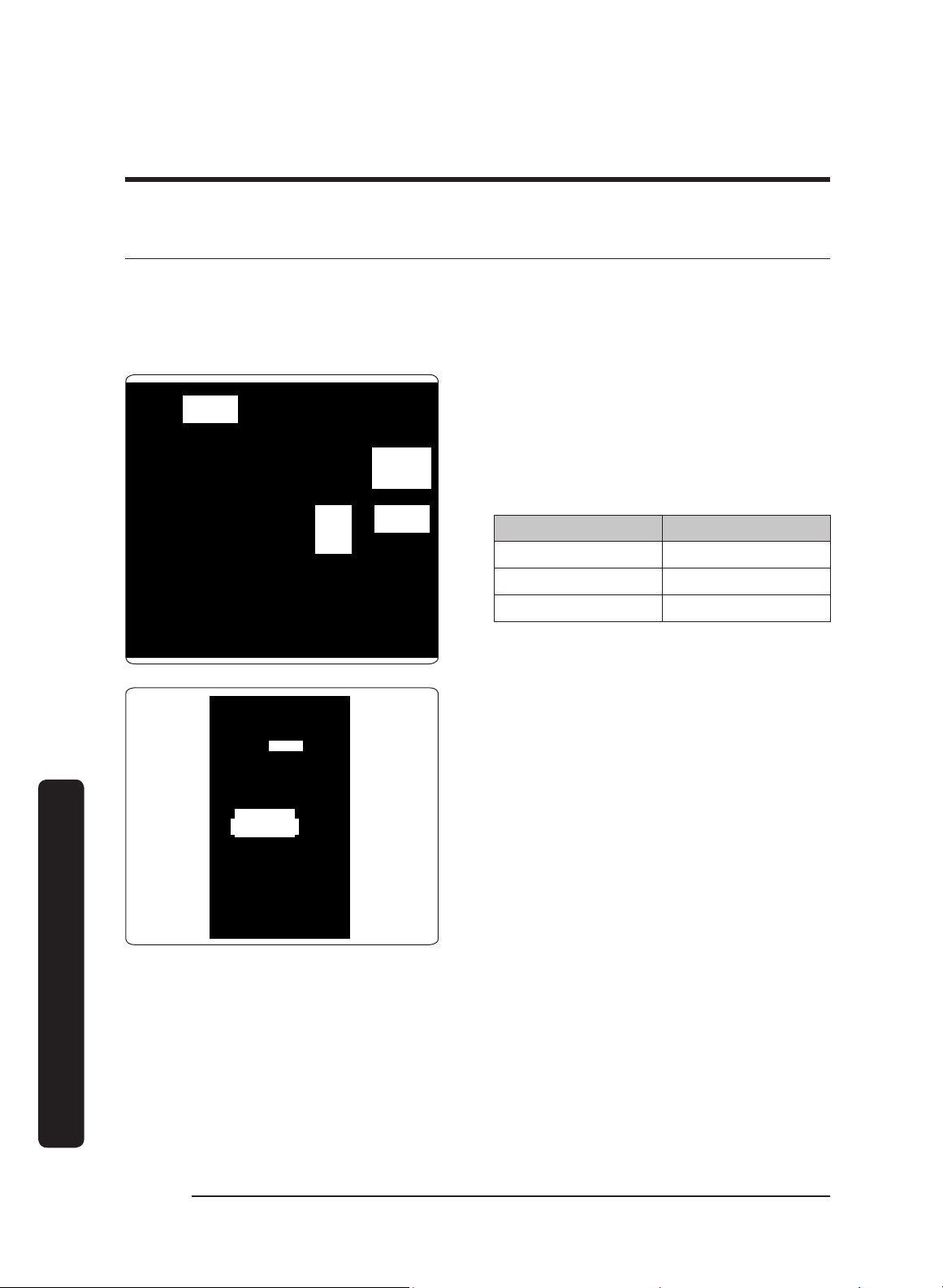
Marking the Exhaust-Duct Centerlines
These measurements/marks help center and level the hood, and mark the duct cutouts.
Have a marking tool, tape measure, and level ready.
Dual
Exhaust
Single
Exhaust
Cooktop
Top-Exhaust Centerline
1. Position the hood as it will be when installed (e.g., for a top-vent installation, set the
hood with the vents on top).
2. Measure the distance from the edge of the hood to the center of the exhaust port.
3. Transfer that measurement to the wall (for a rear vent), or overhead (for top vent).
Measure the X and Y axes to find the centerline.
4. Extend the line down 10 inches (25.4 cm).
5. Cut a hole 1 inch larger than the duct. (Dual-exhaust models require two holes.)
Measurement Location Measurement: in. (cm)
A 9 7/8 in. (25.08 cm)
B 14 1/8 in. (35.88 cm)
C 48 in. (121.92 cm)
D 24 in. (60.96)
IMPORTANT: For dual-exhaust, you need to install the AHT10 Dual-to-Single Transition Kit.
(See the section Using the Dual-to-Single Transition Kit #AHT10)
E 5 3/4 in. (14.6 cm)
English26
Installation instructions
Installation instructions
Installing the Support Brackets
CRITICAL: To avoid alignment issues during final installation, the brackets must not be
over/under/off the centerline.
Hood Area
Bracket
placement
2 1/8"
Mounting block
(attached to
studs inside wall
behind hood)
Stud
(inside wall)
Mounting bracket
(through wall board)
to mounting block
Line
indicates
hood top
Step 4
1 Marking the Centerlines and Brackets 2 Attaching the Brackets to the Wall
Holding-Bracket Centerline Distance
DHD Models A
30 12 1/2 in (31.8 cm)
36 7 1/8 in (18.1 cm)
48 17 in (43.2 cm)
1. Mark the holding bracket’s horizontal centerline 2 1/8 in. (54 cm) below the top of the
hood (Image 1). NOTE: Minimum distance, bottom of cabinets to cooktop: 30 in.
2. Measure and mark the centerline (Image 1) half way between the cabinets. (If there are
no cabinets above the cooktop, measure and mark the cooktop centerline.)
3. Referring to Image 1 and the above table, measure the "A" distance left and right from the
centerline between the cabinets (or the cooktop centerline), and mark the holding
brackets' centerlines.
4. Lay the bracket against the wall, and align the screw holes with the horizontal
centerline. (Use anchors/screws that can support the hood; be sure to properly
reinforce drywall installations.)
5. Mark the two holes in the bracket.
6. Drill those two holes for screws or anchors.
7. Attach the brackets securely to the wall.
English 27
Installation instructions
Blower Rotation (Rear Exhaust)
IMPORTANT: Perform this procedure before you hang the hood.
WARNING
• Install the hood only if the electrical service meets the hood’s specifications; the owner
shall verify proper installation.
• Observe all local codes during installation. Contact your local building department for
details.
• The hood must be installed by a qualified technician with sufficient personnel to assist
with lifting and anchoring the hood.
A B
Top
Exhaust
Rear
Exhaust
The blowers (fans) can be rotated so air
vents out the back of the hood.
The hood comes from the factory in the
top-exhaust configuration; if you intend to
use that configuration, you do not need to
alter the blower’s position.
If, however, the hood will be installed for
rear exhaust, th
e blowers must be rotated
so exhaust vents through the rear.
The images in this section were chosen to illustrate the intended information and may not
exactly represent the hood being installed.
Tools Needed
5/16” Nut driver
Cable ties
• AHT10 Transition kit (option), metal screws, foil tape
• 10” ducts, ducting material
8” Duct and ducting materials
Phillips screwdriver
English28
Installation instructions
Installation instructions
Remove and Replace parts
Disassembling Parts
1. Unhook and remove the grease channel.
2. (Taking care not to scratch the hood)
Place the hood assembly on a large, flat
surface.
Duct Collar (top of hood)
Back of Hood
3. Remove the duct collar from the hood
top. (Save the collar and screws.)
Removing the Blowers(s)
L-Bracket
Plate
Blower
1. Carefully set the hood on its back to
access the bottom.
2. Find the end of the cable assembly
plugged into the bottom left of the
blower, then squeeze and unplug the
connector. (To avoid damaging the
cable-assembly contacts and wires,
always pull by the connector.)
3. Unscrew the cable clamp(s), and remove
the hardware that holds the blower and
L-bracket
.
4. Detach the blower and plate, and set
them aside.
English 29
Installation instructions
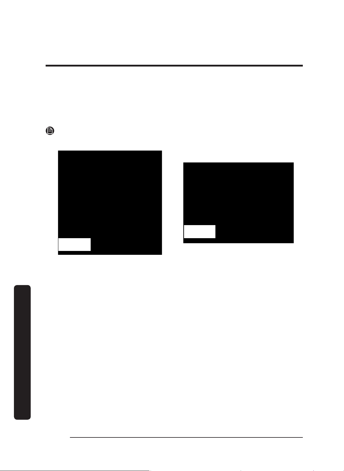
Configuring the Blower/Vent L-Brackets
Default Blower
Configuration:
Top vent open-
No rear vent
Blower/Vent
L-Bracket
Back of Hood
Rotated Blower
Configuration:
Open rear vent-
No top vent
Back of Hood
Blower/Vent
L-Bracket
1. Unscrew, and remove the L-bracket that is in the default top-venting configuration.
2. Turn and align the L-bracket so the hole is in back of the hood, allowing a rear-venting
configuration.
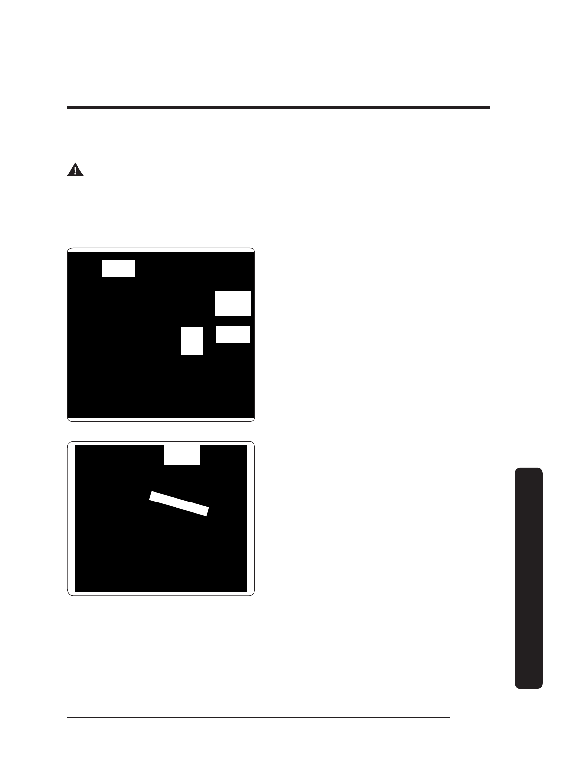
Orientating the Blower(s)
The blower(s) must be correctly positioned.
Hood resting
on its top
Front
Right Side
Left Side
Bottom
Rear
Blower I/O port
(on right for rear
exhaust)
Blower edge
covers exit
vent
1. Set the hood on its top.
2. Standing at the rear of the hood and
looking down at the blower, insert the
blower so its I/O port faces right, and
its exhaust port is against the L-
bracket at the rear of the hood.
English30
Installation instructions
Installation instructions
Finalizing the Rear-Vent Setup
Duct collar
RightRear
Top
1. Refasten the cable clamps and assembly
to the hood.
2. Connect the cable assembly to the
blower’s I/O port.
3. Attach the duct collars to the back of
the hood.
4. Return the hood to a safe, upright
position.
Assembling the Filters
Filters are boxed separately and must be assembled during installation. All needed knobs
and hardware are included.
For correct orientation, ensure the top of the filter faces up. The filter’s face has:
• plastic peel-away coating
• beveled lip on the inside frame
• screw holes on the ridge (not down in the trough)
DHD Baffle-Style Filter
Knob
Beveled
lip
Screw M8
Lock
washer
#10
1. Remove the plastic coating, and make
sure the beveled lip faces up.
2. Align the screw, lock washer, and knob
with the filter. Make sure the knob is
on the ridge, and the screw and lock
washer are in the trough.
3. Twist and tighten the knob onto each
washer/screw.
4. Continue the hood installation, then
install the filters after hanging the
hood.
Replacement Part # Description
702579 Baffle Filter Kit (1 pc + hardware)
702580 Baffle Filter Kit (2 pc + hardware)
English 31
Installation instructions
Using the Dual-to-Single Transition Kit #AHT10
2" (5.1 cm)
3/4"
(1.9 cm)
9" (22.9 cm)
32"
(81.3 cm)
13 3/4"
(34.9 cm)
On dual-exhaust models, the two 8” duct
exhausts can be transitioned into one 10”
duct.
Assemble the Dacor transition kit #AHT10
(sold separately) before you hang the
hood. This transition kit fits over the top/
rear ventilation exits.
Preparing the AHT10
Create a lip around the transition kit by bending the bottom edges outward at right
angles, creating a 3/4” flange around the base.
Bending the Flanges On the Transition Duct
Top/rear vent: Models DHD30/36/48
All four
corners bent
out 90°
English32
Installation instructions
Installation instructions
Installing the AHT10 Transition Kit
Top-/Rear-Vent Configuration
This procedure instructs you how to install the AHT10 Transition Kit for top- and rear-
vent configurations
NOTE
The transition kit does not include the sheet-metal screws needed to install the hood.
Top-Vent Configuration Rear-Vent Configuration
1. Center the transition kit over the duct collars.
2. Drill screwholes in the flanges, being sure to pierce the hood top.
3. With sheet-metal screws, fasten the AHT10 unit to the hood.
4. With foil tape/duct tape, seal the AHT10 unit’s base.
English 33
Installation instructions
Hanging the Hood
WARNING
Hanging the range hood requires two people. Do not lift the hood unassisted.
IMPORTANT: Take care not to scratch/damage the hood.
IMPORTANT: Hanging slots in the hood back engage the holding brackets to support the
hood temporarily during installation.
Bracket
attached to
wall
Bracket
slot (on
hood
back)
Adjacent
Cabinetry
Adjacent
Cabinetry
1. Remove the plastic film from the hood.
2. Lift, and slip the hood onto the holding
brackets through the hanging slots in
the hood back.
3. Adjust the hood into its final position.
4. Mark the spot by drawing in a
mounting hole in the back of the
hood. (This is where a screw will hold
the hood to the wall stud or concrete
anchor.)
Hanging
slots
Mounting holes
5. (If needed) Mark the top of the hood if
the configuration calls for the hood to
be secured at the top.
6. Remove the hood from the wall.
7. Drill the pilot or anchor holes. (If using
anchors, insert them into the anchor
holes.)
8. Re-engage the hood to the holding
brackets.
9. Adjust and anchor the hood to its final
position.
English34
Installation instructions
Installation instructions
Hardwiring the Hood
Power may be suppled to the hood through an electrical junction box or a dedicated 15-
Amp. circuit breaker.
WARNING
• Before connecting the wiring, turn OFF power to the hood at the fuse box or circuit
breaker.
• Miswiring the hood creates an electric shock or fire hazard and may damage its
electrical system.
• Do not ground the wires to the neutral (white) wire. Connect the ground wire to a
separate, properly grounded wire installed by a licensed electrician.
• Use only proper-gauge wire that meets all codes and can accommodate the total
connected loads.
Top Access
Rear Access
1. Shut power OFF at the circuit breaker
or fuse box.
2. Feed the cable assembly through the
hood.
English 35
Installation instructions
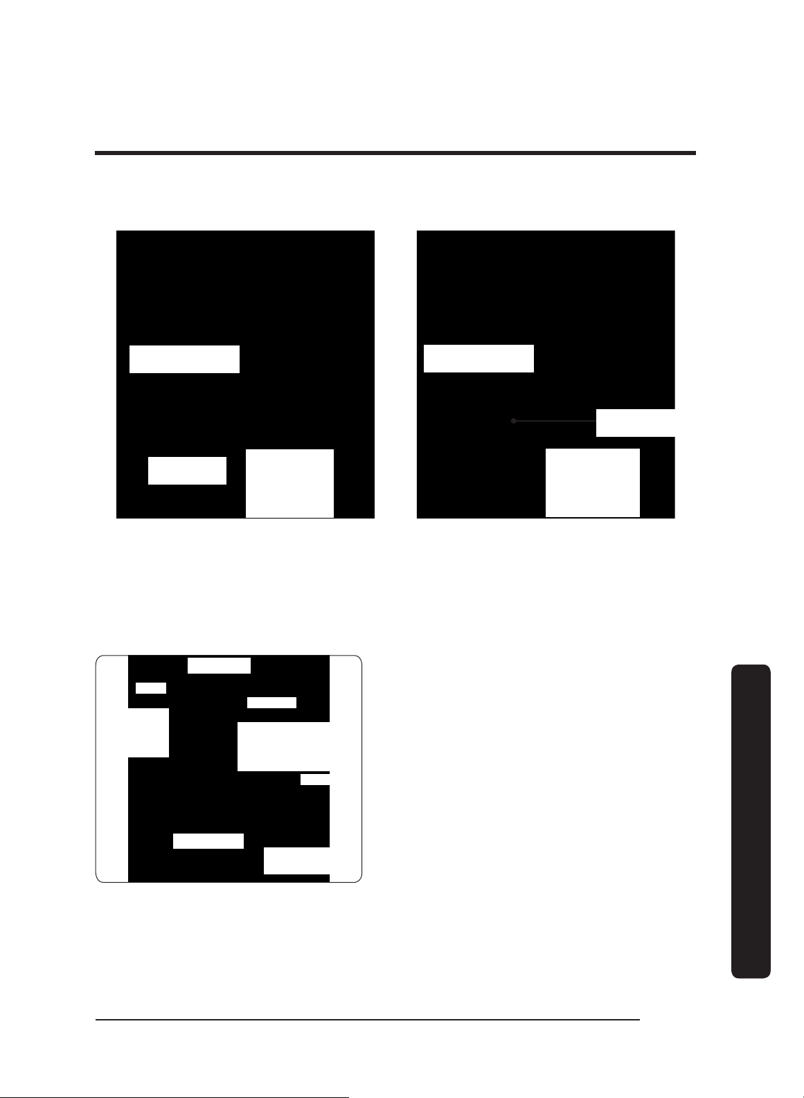
N1
L1
Neutral (white)
Hot (black)
To junction
Box
Power
Terminals
in Hood
Main Power
Switch Detail
Filter
Wing Nut
Main Power
Switch
Grease
Channel
Filter
Ground
Screw
Back
Bottom
3. With the provided green screw, attach
the ground wire to the ground screw
(next to the main power switch inside
the hood above the filters).
IMPORTANT: Use a #10 O-ring at the
end of the ground wire.
4. Remove the wing nut on the main
power switch plate, then remove the
plate to access the terminal block and
connect the power wires.
5. Insert the white wire and black wire
through the plastic hole protector, and
tightly connect the wires to their
corresponding terminals.
Junction box
Wire nut
(3 places)
UL/CSA-approved
NEMA strain relief
To range hood
To house circuit
breaker or fusebox
WHITE
WHITE
BLACK
BLACK
GREEN
GREEN
6. Connect the hood wiring to an electrical
junction box or circuit breaker.
WARNING
• Do not ground the circuit to a gas line
or hot-water pipe.
• Insulated water lines must be jumped
to assure continuity to the ground. (See
the diagram on the next page.)
English36
Installation instructions
Installation instructions
Insulated Pipe Jumper
(if necessary)
Meter
Clamps
Bare metal
No. 4 copper
wire
GREEN
GREEN
WHITE
WHITE
BLACK
BLACK
UL/CSA-approved
NEMA strain relief
Fasten clamp tightly
on metal pipe
Separate No. 10 (minimum)
copper ground wire
To house circuit
breaker panel or
fuse box
To Range Hood
Wire nut,
3 places
Junction box
Meter
No. 4 copper
wire
Clamps
Bare metal
Insulated Pipe Jumper
(if necessary)
Separate No. 10 (minimum)
copper ground wire
Junction box
UL/CSA-approved
NEMA strain relief
To Range Hood
Wire nut,
3 places
To house circuit
breaker panel or
fuse box
WHITE
WHITE
BLACK
BLACK
GREEN
GREEN
Fasten clamp tightly
on metal pipe
Grounding by External Cold-Water Pipe
English 37
Installation instructions
Inserting Light Bulbs
The electronic board was designed for dimmable bulbs. Using non-dimmable bulbs causes
damage and faulty performance.
If needed, clean the lens surface so the suction cup will stick to it. Perform this procedure
for each hood light:
Fixture
Dimmable
Bulb
Suction
Cup
1. (To avoid a possible short and
significant property damage) Shut the
main circuit breaker OFF.
2. Attach the suction cup to the bulb lens
(both supplied, see the graphic).
3. Screw the bulb into the light fixture,
and remove the suction cup.
4. Switch the main circuit power ON.
Replacement Part # Description
702666
Dimmable LED Bulb Replacement Kit
(1 bulb + 1 suction-cup tool)
English38
Installation instructions
Installation instructions
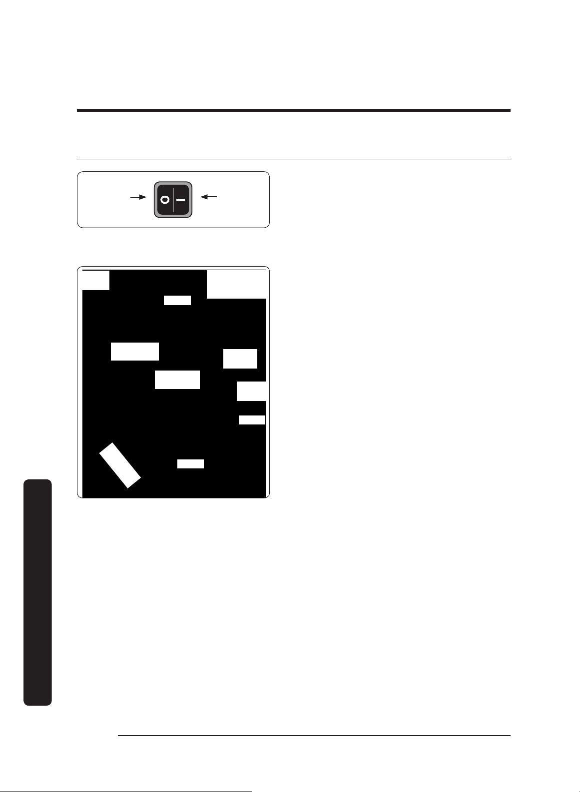
Verifying the Setup
ONOFF
Main Power
Switch Detail/
Hood Bottom
Filter
Main Power
Switch
Grease
Channel
Filter
Back
Bottom
Front Filter
Clip
Grease
Channel
Lights
1. Turn OFF the main power switch.
2. Turn power ON at the circuit-breaker
panel or fusebox.
3. Turn ON the main power switch.
The button panel flashes several times
during startup.
4. (Taking care not to scratch the grease
channel o
r other surfaces) Insert the
filters:
a. Set the front edge into the clip, and
press forward.
b. Lift the rear edge above the grease
channel.
c. Set the filter rear edge on the grease
channel.
5. On the hood feature-button panel, press
Lights to verify that all lights turn on.
6. Press Lights again to turn the lights to the Low setting.
7. Press
Lights again to turn the lights off.
8. Press POWER to verify that one fan-speed indicator turns on and the fan is on at low
speed.
9. Press Low/Med/High/Boost: to verify that the fan speed increases each time.
10. Press POWER again to turn the fan OFF.

English 39
Installation instructions
If the Hood Fails to Function Correctly
1. Verify that the hood receives power.
2. Remove the right-most filter to access the main power switch, and confirm the switch
is ON.
3. Verify that the electrical connections are correct.
4. Perform the Verifying the Setup procedure again.
IMPORTANT
: If the hood still does not work, contact Dacor Distinctive Service: (800)
793-0093 x2822. Do not try to repair the hood yourself. Dacor is not responsible for
service required to correct a faulty installation.
English40
Installation instructions
Installation instructions
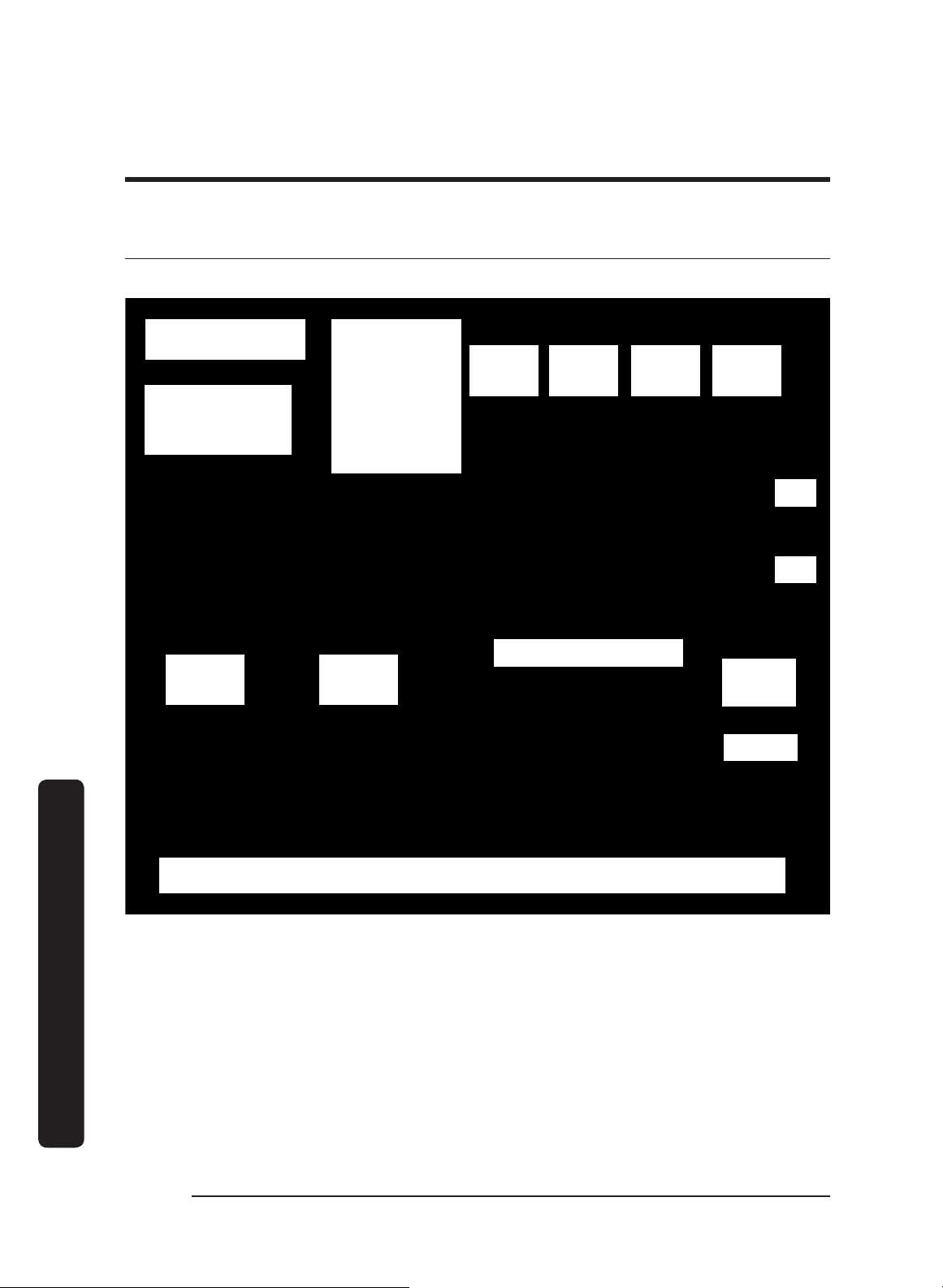
Wiring Diagram
DHD30/36/48
WIRING DIAGRAM
DHD30, 36, 48 SERIES
WIRE COLOR CODE
W-WHITE
B-BLACK
Y-YELLOW
O-ORANGE
R-RED
BL-BLUE
BR-BROWN
G-GREEN
V-VIOLET
GR-GREY
HOOD
LED 7.5 W
(75 W MAX)
HOOD
LED 7.5 W
(75 W MAX)
HOOD
LED 7.5 W
(75 W MAX)
HOOD
LED 7.5 W
(75 W MAX)
BLOWER
120 V/60 HZ
350 W
BLOWER
120 V/60 HZ
350 W
10K THERMISTOR
P/N: 110301
NOTE
DHD30: 2 LIGHTS, 1 FAN
DHD36: 3 LIGHTS, 1 FAN
DHD30: 4 LIGHTS, 2 FANS
CONNECT TO
120 V, 60 Hz, 15 A
SINGLE-PHASE
POWER SUPPLY
CHASSIS
GROUND
POWER
SWITCH
CAUTION:
DISCONNECT POWER SUPPLY AT FUSE BOX BEFORE SERVICING THIS EQUIPMENT
HOOD POWER & CONTROL BOARD
P/N: 110302

MEMO

MEMO

MEMO

Dacor ∙ 14425 Clark Avenue, City of Industry, CA 91745 ∙ Phone: (800) 793-0093 ∙ Fax: (626) 403-3130 ∙ www.dacor.com