
4-234-334-12(2)
FM Stereo
FM-AM Receiver
Operating Instructions
2001 Sony Corporation
STR-DE975
STR-DE875
2
WARNING
To prevent fire or shock
hazard, do not expose the
unit to rain or moisture.
This symbol is intended to alert the user to
the presence of uninsulated “dangerous
voltage” within the product’s enclosure
that may be of sufficient magnitude to
constitute a risk of electric shock to
persons.
This symbol is intended to alert the user to
the presence of important operating and
maintenance (servicing) instructions in the
literature accompanying the appliance.
INFORMATION
This equipment has been tested and found
to comply with the limits for a Class B
digital device, pursuant to Part 15 of the
FCC Rules.
These limits are designed to provide
reasonable protection against harmful
interference in a residential installation.
This equipment generates, uses, and can
radiate radio frequency energy and, if not
installed and used in accordance with the
instructions, may cause harmful
interference to radio communications.
However, there is no guarantee that
interference will not occur in a particular
installation. If this equipment does cause
harmful interference to radio or television
reception, which can be determined by
turning the equipment off and on, the user
is encouraged to try to correct the
interference by one or more of the
following measures:
– Reorient or relocate the receiving
antenna.
– Increase the separation between the
equipment and receiver.
– Connect the equipment into an outlet on
a circuit different from that to which the
receiver is connected.
– Consult the dealer or an experienced
radio/TV technician for help.
CAUTION
You are cautioned that any changes or
modification not expressly approved in
this manual could void your authority to
operate this equipment.
Note to CATV system installer:
This reminder is provided to call CATV
system installer’s attention to Article 820-
40 of the NEC that provides guidelines for
proper grounding and, in particular,
specifies that the cable ground shall be
connected to the grounding system of the
building, as close to the point of cable
entry as practical.
Owner’s Record
The model and serial numbers are located
on the rear of the unit. Record the serial
number in the space provided below.
Refer to them whenever you call upon
your Sony dealer regarding this product.
Model No. STR-DE975/DE875
Serial No.
For customers in Canada
CAUTION
TO PREVENT ELECTRIC SHOCK, DO
NOT USE THIS POLARIZED AC PLUG
WITH AN EXTENSION CORD,
RECEPTACLE OR OTHER OUTLET
UNLESS THE BLADES CAN BE FULLY
INSERTED TO PREVENT BLADE
EXPOSURE.
For customers in the United States and
Canada
ENERGY STAR
®
is a U.S.
registered mark.
As an ENERGY STAR
®
partner, Sony Corporation
has determined that this
product meets the ENERGY
STAR
®
guidelines for
energy efficiency.
Don't throw a battery,
dispose it as the
injurious wastes.
Precautions
On safety
• Should any solid object or liquid fall into the
cabinet, unplug the receiver and have it
checked by qualified personnel before
operating it any further.
• To prevent fire, do not cover the ventilation
of the receiver with newspapers, table cloths,
curtains, etc. And don’t place lighted candles
on the receiver.
• To prevent fire or shock hazards, do not place
vases on the receiver.
On power sources
• Before operating the receiver, check that the
operating voltage is identical with your local
power supply. The operating voltage is
indicated on the nameplate at the rear of the
receiver.
• The unit is not disconnected from the AC
power source (mains) as long as it is
connected to the wall outlet, even if the unit
itself has been turned off.
• If you are not going to use the receiver for a
long time, be sure to disconnect the receiver
from the wall outlet. To disconnect the AC
power cord, grasp the plug itself; never pull
the cord.
• One blade of the plug is wider than the other
for the purpose of safety and will fit into the
wall outlet only one way. If you are unable to
insert the plug fully into the outlet, contact
your dealer.
• AC power cord must be changed only at the
qualified service shop.
On placement
• Place the receiver in a location with adequate
ventilation to prevent heat buildup and
prolong the life of the receiver.
• Do not place the receiver near heat sources,
or in a place subject to direct sunlight,
excessive dust or mechanical shock.
• Do not place anything on top of the cabinet
that might block the ventilation holes and
cause malfunctions.
• Although the receiver heats up during
operation, this is not a malfunction. If you
continuously use this receiver at a large
volume, the cabinet temperature of the top,
side and bottom rises accordingly. To avoid
burning yourself, do not touch the cabinet.
On operation
Before connecting other components, be sure to
turn off and unplug the receiver.
On cleaning
Clean the cabinet, panel and controls with a soft
cloth slightly moistened with a mild detergent
solution. Do not use any type of abrasive pad,
scouring powder or solvent such as alcohol or
benzine.
If you have any question or problem
concerning your receiver, please consult
your nearest Sony dealer.
3
About This Manual
The instructions in this manual are for the STR-DE975,
and STR-DE875. Check your model number by looking at
the lower right corner of the front panel or lower right
corner of the remote. In this manual, the STR-DE975 and
the remote commander RM-PP505 are used for illustration
purposes unless stated otherwise. Any difference in
operation is clearly indicated in the text, for example,
“STR-DE975 only”.
Type of differences
About area codes
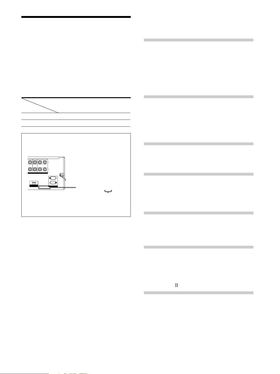
The area code of the receiver you purchased is shown on the
lower portion of the rear panel (see the illustration below).
Any differences in operation, according to the area code, are
clearly indicate in the text, for example, “Models of area code
AA only”.
Conventions
• The instructions in this manual describe the controls on
the receiver. You can also use the controls on the
supplied remote if they have the same or similar names
as those on the receiver.
• The following icon is used in this manual:
zIndicates hints and tips for making the task easier.
This receiver incorporates Dolby* Digital and Pro Logic
Surround and the DTS** Digital Surround System.
*
Manufactured under license from Dolby Laboratories.
“Dolby”, “Pro Logic” and the double-D symbol a are trademarks of
Dolby Laboratories.
Confidential unpublished Works. © 1992-1997 Dolby Laboratories.
All rights reserved.
**
Manufactured under license from Digital Theater Systems, Inc. US
Pat. No. 5,451,942, 5,956,674, 5,974,380, 5,978,762 and other
world-wide patents issued and pending. “DTS”, “ES” and “DTS
Digital Surround” are registered trademarks of Digital Theater
Systems, Inc. Copyright 1996, 2000 Digital Theater Systems, Inc.
All Rights Reserved.
Feature
Model
5 audio inputs
4 audio inputs
DE975
•
DE875
•
FRONT
SWITCHED 120W/1A MAX
AC 120V 60Hz
4
Ω
8
Ω
AC OUTLET
IMPEDANCE
SELECTOR
R
ROUND CENTER FRONT
M
PEDANCE USE 8 – 16
Ω
IMPEDANCE USE 4 – 16
Ω
L
R
L
SPEAKERS
4-XXX-XXX-XX AA
Area code
TABLE OF CONTENTS
Hooking Up the Components 4
Unpacking 4
Antenna Hookups 5
Audio Component Hookups 6
Video Component Hookups 8
Digital Component Hookups 9
MULTI CH IN Hookups 11
Other Hookups 12
Hooking Up and Setting Up the
Speaker System 15
Speaker System Hookup 16
Performing Initial Setup Operations 18
Multi Channel Surround Setup 19
Before You Use Your Receiver 24
Location of Parts and Basic
Operations 25
Front Panel Parts Descriptions 25
Enjoying Surround Sound 30
Selecting a Sound Field 31
Understanding the Multi-Channel Surround
Displays 34
Customizing Sound Fields 36
Receiving Broadcasts 44
Direct Tuning 46
Automatic Tuning 46
Preset Tuning 47
Other Operations 48
Naming Preset Stations and Program Sources 49
Recording 49
Using the Sleep Timer 50
Adjustment Using the SET UP Button 51
CONTROL A1 Control System 53
Additional Information 55
Troubleshooting 55
Specifications 57
Glossary 59
Table of settings using SURR, LEVEL, EQ, and SET
UP buttons 60
Remote Button Description 63
Index 71
4
Hooking Up
the
Components
This chapter describes how to connect
various audio and video components
to the receiver. Be sure to read the
sections for the components you have
before you actually connect them to
the receiver.
Unpacking
Check that you received the following items with the
receiver:
• FM wire antenna (1)
• AM loop antenna (1)
• R6 (size-AA) batteries (2)
• Audio/video/control S connecting cord (1)
• Control S connecting cord (1)
• STR-DE975 only
• Remote commander RM-PP505L (remote) (1)
• STR-DE875 only
• Remote commander RM-PP505 (remote) (1)
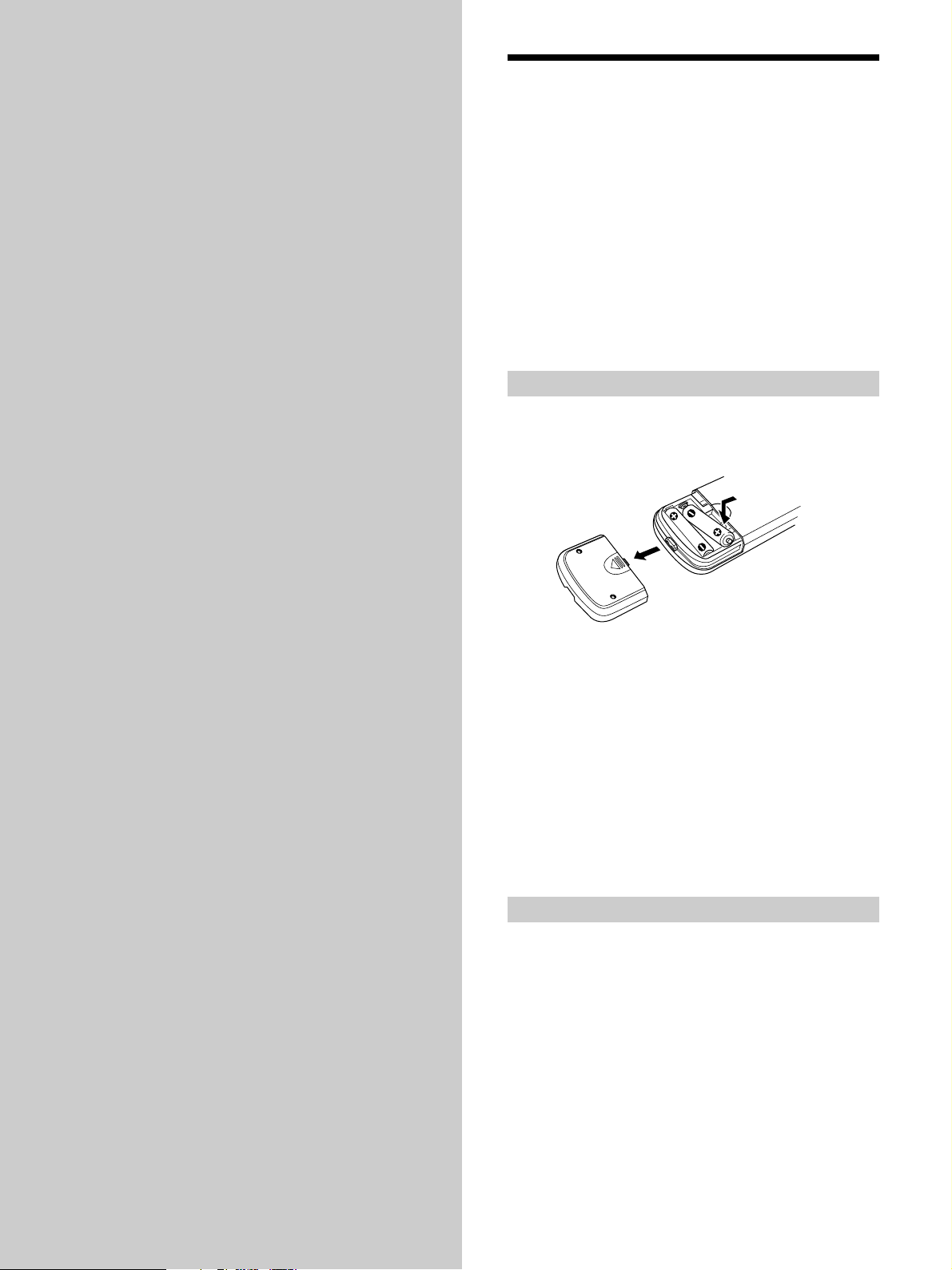
Inserting batteries into the remote
Insert R6 (size-AA) batteries with the + and – properly
oriented in the battery compartment. When using the
remote, point it at the remote sensor g on the receiver.
z
When to replace batteries
Under normal conditions, the batteries should last for about 6
months. When the remote no longer operates the receiver, replace
all batteries with new ones.
Notes
• Do not leave the remote in an extremely hot or humid place.
• Do not use a new battery with an old one.
• Do not expose the remote sensor to direct sunlight or lighting
apparatuses. Doing so may cause a malfunction.
• If you don’t use the remote for an extended period of time,
remove the batteries to avoid possible damage from battery
leakage and corrosion.
Before you get started
• Turn off the power to all components before making
any connections.
• Do not connect the AC power cords until all of the
connections are completed.
• Be sure to make connections firmly to avoid hum and
noise.
• When connecting an audio/video cord, be sure to
match the color-coded pins to the appropriate jacks on
the components: yellow (video) to yellow; white (left,
audio) to white; and red (right, audio) to red.
5
Hooking Up the Components
SIGNAL GND
DIGITAL
MD/DAT OUT
MD/DAT IN
TV/SAT IN
DVD/LD IN
OPTICAL
COAXIAL
DVD/LD
IN
AUDIO IN AUDIO IN AUDIO OUT
AUDIO
OUT
AUDIO OUTAUDIO IN AUDIO IN
VIDEO OUT
VIDEO IN VIDEO IN VIDEO IN VIDEO IN
FRONT
VIDEO OUT
SWITCHED 120W/1A MAX
AC 120V 60Hz
4
Ω 8Ω
VIDEO OUT
S-VIDEO
OUT
S-VIDEO
OUT
S-VIDEO
IN
S-VIDEO
IN
S-VIDEO
IN
CTRL S
IN
CTRL S
OUT
CTRL S
OUT
CTRL S
STATUS IN
ANTENNA
COAXIAL
FM
75
Ω
SUB
WOOFER
INOUT
TAPE
MONITOR
TV/SAT DVD/LD
VIDEO 2 VIDEO 1
AC OUTLET
IMPEDANCE
SELECTOR
R
L
R
R
L
R
L
SURROUND CENTER FRONT
IMPEDANCE USE 8 – 16Ω IMPEDANCE USE 4 – 16Ω
R
L
R
L
SPEAKERS
R
L
SUB
WOOFER
MULTI CH IN
FRONT SURROUND
CENTER
IN INOUT
CD/SACD
IN
PHONO
R
L
R
L
MD/DAT
AM
CONTROL A1
2ND ROOM
L
U
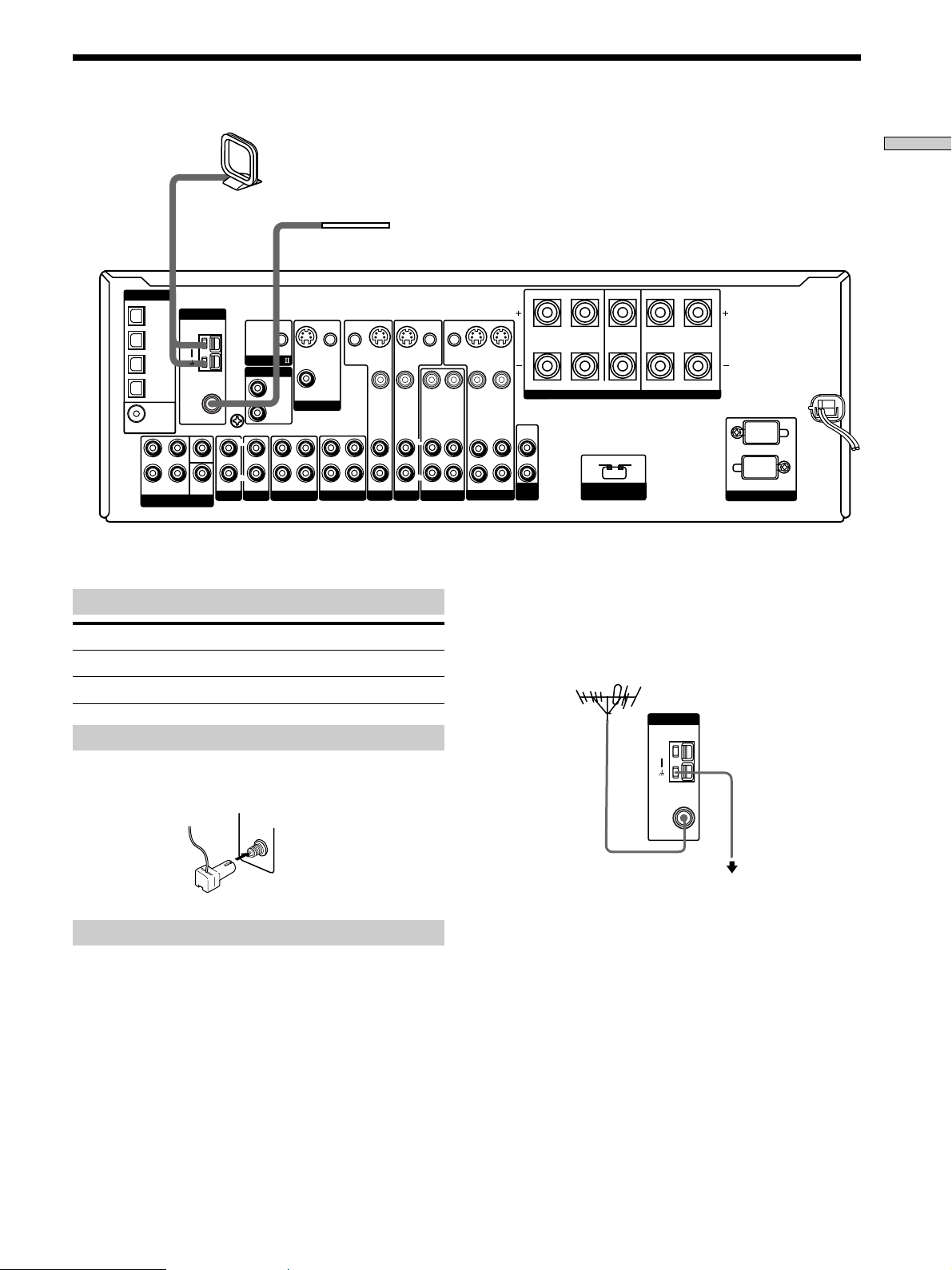
FM wire antenna
(supplied)
AM loop antenna
(supplied)
Terminals for connecting the antennas
Connect the To the
AM loop antenna AM terminals
FM wire antenna FM 75Ω COAXIAL terminal
Antenna Hookups
ANTENNA
AM
COAXIAL
FM
75
Ω
Important
If you connect the receiver to an outdoor antenna, ground
it against lightning. To prevent a gas explosion, do not
connect the ground wire to a gas pipe.
Note
Do not use the U SIGNAL GND terminal for grounding the
receiver.
Assembling the supplied FM antenna
The supplied FM wire antenna must be connected to the
supplied FM antenna adaptor.
Notes on antenna hookups
• To prevent noise pickup, keep the AM loop antenna
away from the receiver and other components.
• Be sure to fully extend the FM wire antenna.
• After connecting the FM wire antenna, keep it as
horizontal as possible.
Ground wire
(not supplied)
To ground
z
If you have poor FM reception
Use a 75-ohm coaxial cable (not supplied) to connect the receiver
to an outdoor FM antenna as shown below.
Outdoor FM antenna
Receiver
COAXIAL
FM
75Ω
6
Hooking Up the Components
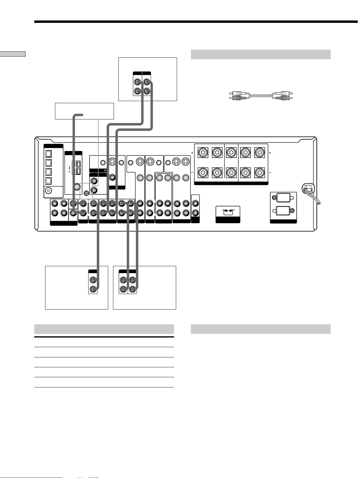
White (L) White (L)
Red (R) Red (R)
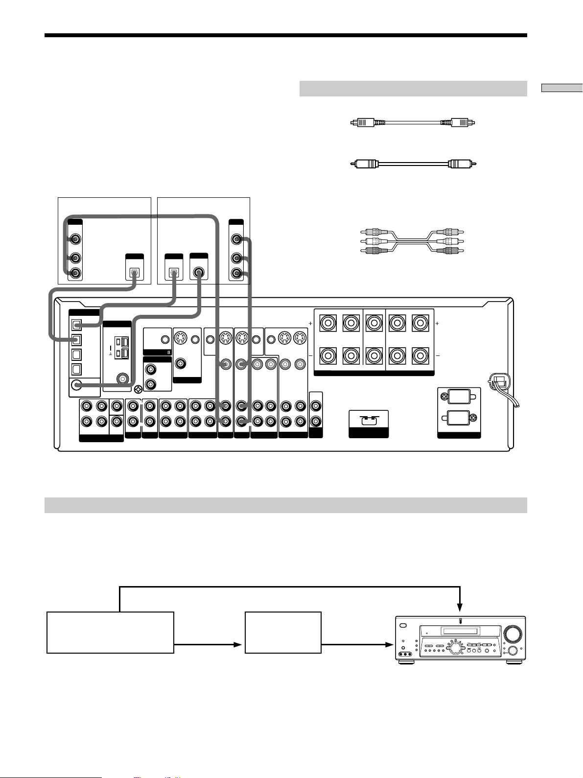
Required cords
Audio cords (not supplied)
When connecting a cord, be sure to match the color-coded pins to
the appropriate jacks on the components.
Audio Component Hookups
Turntable
Tape deck
MD/DAT deck
CD or SACD player
STR-DE975
Jacks for connecting audio components
Connect a To the
Turntable PHONO jacks
CD or SACD player CD/SACD jacks
Tape deck TAPE jacks
MD deck or DAT deck MD/DAT jacks
Note on audio component hookups
If your turntable has a ground wire, connect it to the
U SIGNAL GND terminal on the receiver.
SIGNAL GND
DIGITAL
MD/DAT OUT
MD/DAT IN
TV/SAT IN
DVD/LD IN
OPTICAL
COAXIAL
DVD/LD
IN
AUDIO IN AUDIO IN AUDIO OUT
AUDIO
OUT
AUDIO OUTAUDIO IN AUDIO IN
VIDEO OUT
VIDEO IN VIDEO IN VIDEO IN VIDEO IN
FRONT
VIDEO OUT
SWITCHED 120W/1A MAX
AC 120V 60Hz
4
Ω 8Ω
VIDEO OUT
S-VIDEO
OUT
S-VIDEO
OUT
S-VIDEO
IN
S-VIDEO
IN
S-VIDEO
IN
CTRL S
IN
CTRL S
OUT
CTRL S
OUT
CTRL S
STATUS IN
ANTENNA
FM
75
Ω
SUB
WOOFER
INOUT
MONITOR
DVD/LD
VIDEO 2 VIDEO 1
AC OUTLET
IMPEDANCE
SELECTOR
R
L
R
L
R
L
SURROUND CENTER FRONT
IMPEDANCE USE 8 – 16Ω IMPEDANCE USE 4 – 16Ω
R
L
R
L
SPEAKERS
R
L
SUB
WOOFER
MULTI CH IN
FRONT SURROUND
CENTER
IN INOUT
CD/SACD
IN
PHONO
R
L
R
L
MD/DAT
CONTROL A1
2ND ROOM
AM
U
R
L
INOUT
LINE
L
R
LINE
INPUT OUTPUT
LINE
L
R
LINE
INPUT OUTPUT
LINE
L
R
OUTPUT
ç
ç
ç
ç
CENTER
INOUT
TAPE
TV/SAT
COAXIAL
7
Hooking Up the Components
SIGNAL GND
DIGITAL
MD/TAPE OUT
MD/TAPE IN
TV/SAT IN
DVD/LD IN
OPTICAL
COAXIAL
DVD/LD
IN
AUDIO IN AUDIO IN AUDIO OUT
AUDIO
OUT
AUDIO OUTAUDIO IN AUDIO IN
VIDEO OUT
VIDEO IN VIDEO IN VIDEO IN VIDEO IN
FRONT
VIDEO OUT
SWITCHED 120W/1A MAX
AC 120V 60Hz
4
Ω 8Ω
VIDEO OUT
S-VIDEO
OUT
S-VIDEO
OUT
S-VIDEO
IN
S-VIDEO
IN
S-VIDEO
IN
CTRL S
IN
CTRL S
OUT
CTRL S
OUT
CTRL S
STATUS IN
COAXIAL
FM
75
Ω
SUB
WOOFER
TV/SAT DVD/LD
VIDEO 2 VIDEO 1
AC OUTLET
IMPEDANCE
SELECTOR
R
L
R
L
R
L
SUB
WOOFER
MULTI CH IN
FRONT SURROUND
IN INOUT
CD/SACD
IN
PHONO
R
L
R
L
MD/TAPE
CONTROL A1
AM
U
SURROUND CENTER FRONT
IMPEDANCE USE 8 – 16Ω IMPEDANCE USE 4 – 16Ω
R
L
R
L
SPEAKERS
INOUT
LINE
L
R
LINE
INPUT OUTPUT
LINE
L
R
OUTPUT
ç
ç
CENTER
ANTENNA
MONITOR
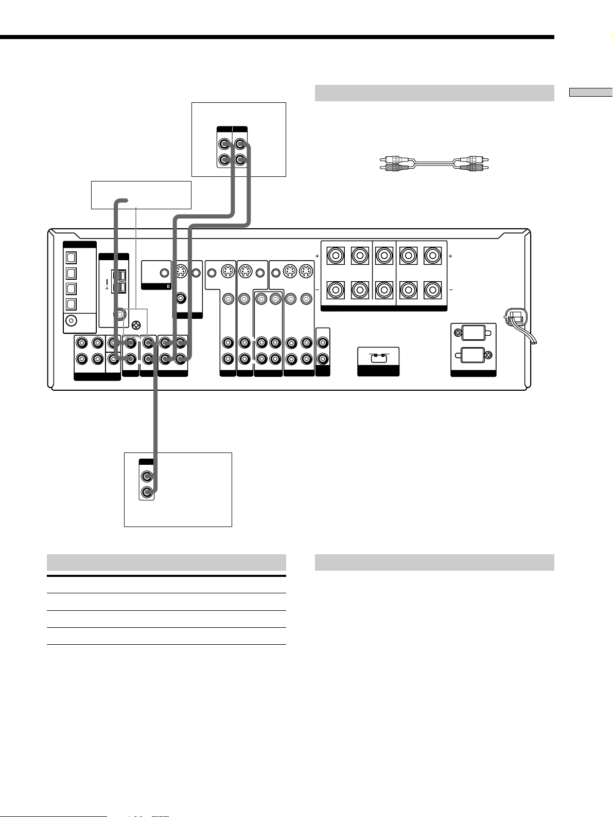
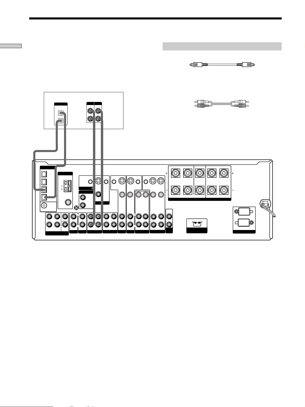
White (L) White (L)
Red (R) Red (R)
Jacks for connecting audio components
Connect a To the
Turntable PHONO jacks
CD or SACD player CD/SACD jacks
MD deck or tape deck MD/TAPE jacks
Required cords
Audio cords (not supplied)
When connecting a cord, be sure to match the color-coded pins to
the appropriate jacks on the components.
Turntable
MD/Tape deck
CD or SACD player
STR-DE875
Note on audio component hookups
If your turntable has a ground wire, connect it to the
U SIGNAL GND terminal on the receiver.
8
Hooking Up the Components
SIGNAL GND
DIGITAL
MD/DAT OUT
MD/DAT IN
TV/SAT IN
DVD/LD IN
OPTICAL
COAXIAL
DVD/LD
IN
AUDIO IN AUDIO IN AUDIO OUT
AUDIO
OUT
AUDIO OUTAUDIO IN AUDIO IN
VIDEO OUT
VIDEO IN VIDEO IN VIDEO IN VIDEO IN
FRONT
VIDEO OUT
SWITCHED 120W/1A MAX
AC 120V 60Hz
4
Ω 8Ω
VIDEO OUT
S-VIDEO
OUT
S-VIDEO
OUT
S-VIDEO
IN
S-VIDEO
IN
S-VIDEO
IN
CTRL S
IN
CTRL S
OUT
CTRL S
OUT
CTRL S
STATUS IN
ANTENNA
COAXIAL
FM
75
Ω
SUB
WOOFER
INOUT
MONITOR
TV/SAT DVD/LD
AC OUTLET
IMPEDANCE
SELECTOR
R
L
R
L
R
L
SURROUND CENTER FRONT
IMPEDANCE USE 8 – 16Ω IMPEDANCE USE 4 – 16Ω
R
L
R
L
SPEAKERS
R
L
SUB
WOOFER
MULTI CH IN
FRONT SURROUND
CENTER
IN INOUT
CD/SACD
IN
PHONO
R
L
R
L
MD/DAT
CONTROL A1
2ND ROOM
AM
U
R
L
VIDEO
OUT
R
AUDIO
OUT
VIDEO
IN
AUDIO
IN
OUTPUTINPUT
L
INOUT
AUDIO OUT VIDEO
OUT
L
R
OUTPUT
AUDIO OUT VIDEO
OUT
L
R
OUTPUT
VIDEO
OUT
R
AUDIO
OUT
VIDEO
IN
AUDIO
IN
INPUT
L
VIDEO
IN
INPUT
Ç
Ç
INOUT
Ç
Ç
OUTPUT
TAPE
VIDEO 2 VIDEO 1
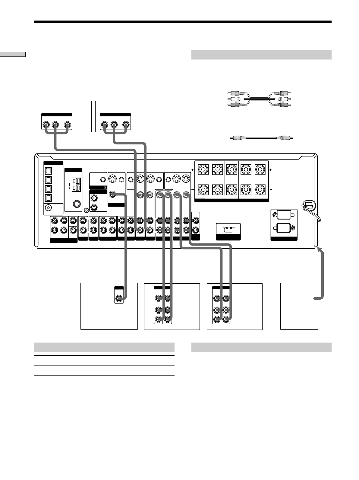
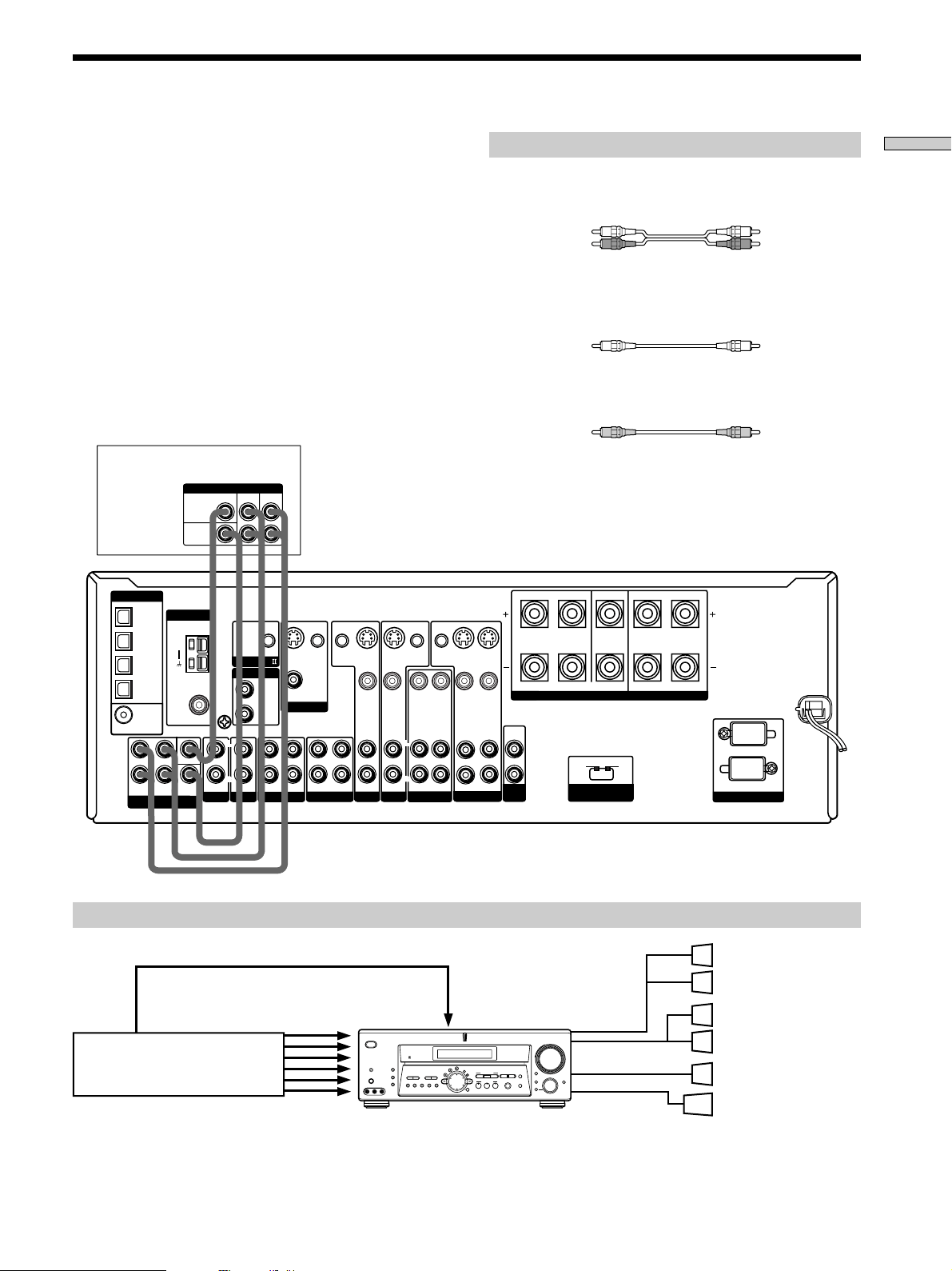
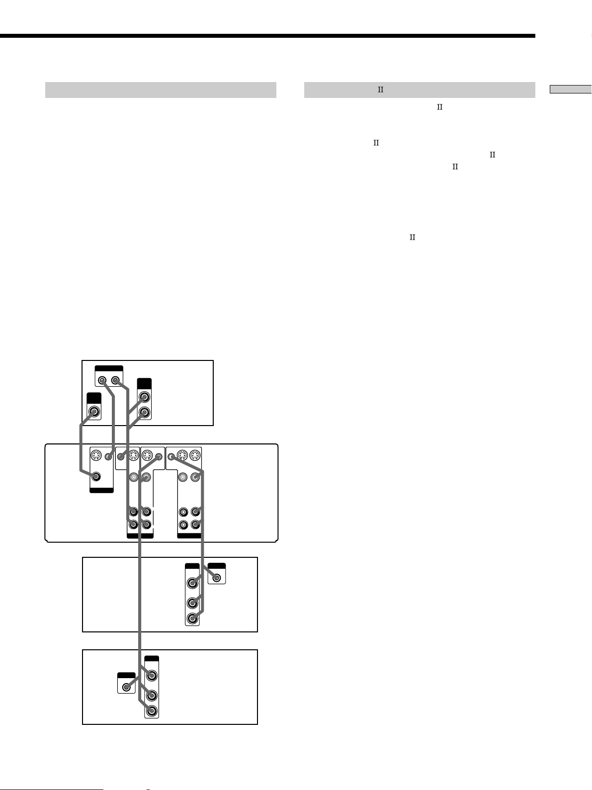
Note on video component hookups
You can connect your TV’s audio output jacks to the TV/
SAT AUDIO IN jacks on the receiver and apply sound
effects to the audio from the TV. In this case, do not
connect the TV’s video output jack to the TV/SAT VIDEO
IN jack on the receiver. If you are connecting a separate
TV tuner (or satellite tuner), connect both the audio and
video output jacks to the receiver as shown above.
z
When using the S-video jacks instead of the video jacks
Your monitor must also be connected via an S-video jack. S-video
signals are on a separate bus from the video signals and will not
be output through the video jacks.
Jacks for connecting video components
Connect a To the
TV or satellite tuner TV/SAT jacks
VCR VIDEO 1 jacks
Additional VCR VIDEO 2 jacks
DVD or LD player DVD/LD jacks
TV monitor
1)
MONITOR VIDEO OUT jack
1) For STR-DE975, you can display the SET UP, SURR, LEVEL and
EQ parameters and the current sound field by pressing ON
SCREEN.
Required cords
Audio/video cords (not supplied)
When connecting a cord, be sure to match the color-coded pins to
the appropriate jacks on the components.
Video cord for connecting a TV monitor (not supplied)
Video Component Hookups
Yellow Yellow
Yellow (video) Yellow (video)
White (L/audio) White (L/audio)
Red (R/audio) Red (R/audio)
To the front panel
Camcorder
or video
game
(STR-DE975
only)
TV or satellite tuner
DVD or LD player
TV monitor VCR VCR
9
Hooking Up the Components
SIGNAL GND
DIGITAL
MD/DAT OUT
MD/DAT IN
TV/SAT IN
DVD/LD IN
OPTICAL
COAXIAL
DVD/LD
IN
AUDIO IN AUDIO IN AUDIO OUT
AUDIO
OUT
AUDIO OUTAUDIO IN AUDIO IN
VIDEO OUT
VIDEO IN VIDEO IN VIDEO IN VIDEO IN
FRONT
VIDEO OUT
SWITCHED 120W/1A MAX
AC 120V 60Hz
4
Ω 8Ω
VIDEO OUT
S-VIDEO
OUT
S-VIDEO
OUT
S-VIDEO
IN
S-VIDEO
IN
S-VIDEO
IN
CTRL S
IN
CTRL S
OUT
CTRL S
OUT
CTRL S
STATUS IN
ANTENNA
COAXIAL
FM
75
Ω
SUB
WOOFER
INOUT
TAPE
MONITOR
TV/SAT DVD/LD
VIDEO 2 VIDEO 1
AC OUTLET
IMPEDANCE
SELECTOR
R
L
R
L
R
L
SURROUND CENTER FRONT
IMPEDANCE USE 8 – 16Ω IMPEDANCE USE 4 – 16Ω
R
L
R
L
SPEAKERS
R
L
SUB
WOOFER
MULTI CH IN
FRONT SURROUND
CENTER
IN INOUT
CD/SACD
IN
PHONO
R
L
R
L
MD/DAT
CONTROL A1
2ND ROOM
AM
U
R
L
VIDEO
OUT
R
AUDIO
OUT
OUTPUT
L
DIGITAL
COAXIAL
OUTPUT
VIDEO
OUT
R
AUDIO
OUT
OUTPUT
L
DIGITAL
OPTICAL
OUTPUT
DIGITAL
OPTICAL
OUTPUT
DVD/LD
VIDEO IN
DIGITAL
DVD/LD IN
(COAXIAL)
(OPTICAL)
DOLBY DIGITAL
RF OUT
VIDEO OUT
? / 1
DISPLAY
DIMMER
ON SCREEN
MEMORY SHIFT FM MODE FM AM
PRESET
TUNING
TUNING
–
+
–
+
MULTI CHANNEL DECODING
A.F.D.
SOUND FIELD
MULTI /2CH A. DIRECT
DIGITAL CONCERT HALL
EQUALIZER
MUTING
INPUT MODE
MODE
2ND ROOM
FUNCTION
6.1 CH DECODING
CINEMA STUDIO EX
AA
MODE 2CH
PHONES
VIDEO 3 INPUT
VIDEO L AUDIO R
SPEAKERS
EQ
SURR
LEVEL
SET UP
NAME
ENTER
BBC
MASTER VOLUME
+
–
Required cords
Optical digital cords (not supplied)
Coaxial digital cord (not supplied)
Audio/video cords (not supplied)
When connecting a cord, be sure to match the color-coded pins to
the appropriate jacks on the components.
Connect the digital output jacks of your DVD player and
satellite tuner (etc.) to the receiver’s digital input jacks to
bring the multi channel surround sound of a movie
theater into your home. To enjoy full effect of multi
channel surround sound, five speakers (two front
speakers, two surround speakers, and a center speaker)
and a sub woofer are required. You can also connect an
LD player with an RF OUT jack via an RF demodulator,
such as the Sony MOD-RF1 (not supplied).
Digital Component Hookups
Example of LD player connected via an RF demodulator
Please note that you cannot connect an LD player’s DOLBY DIGITAL RF OUT jack directly to the receiver’s digital input
jacks. You must first convert the RF signal to either an optical or coaxial digital signal. Connect the LD player to the RF
demodulator, then connect the RF demodulator’s optical or coaxial digital output to the receiver’s OPTICAL or COAXIAL
DVD/LD IN jack. Refer to the instruction manual supplied with your RF Demodulator for details on DOLBY DIGITAL RF
hookups.
RF demodulator
LD player
Black Black
Yellow Yellow
Yellow (video) Yellow (video)
White (L/audio) White (L/audio)
Red (R/audio) Red (R/audio)
DIGITAL
DVD/LD IN
(COAXIAL)
or (OPTICAL)
Note
When making connections as shown above, be sure to set INPUT MODE (qa on page 27) manually. The receiver may not operate correctly
if INPUT MODE is set to “AUTO 2CH” or “AUTO MULTI CH”.
*
When making digital audio connections to a DVD player, connect to either the coaxial OR optical digital jacks, and not both. It is recommended to
make digital audio connections to the coaxial jack.
DVD or LD player (etc.)*
TV or satellite tuner
10
Hooking Up the Components
White (L) White (L)
Red (R) Red (R)
Required cords
Optical digital cords (not supplied)
Audio cords (not supplied)
When connecting a cord, be sure to match the color-coded pins to
the appropriate jacks on the components.
Connect the digital output jacks of your MD or DAT deck
to the receiver’s digital input jack and connect the digital
input jacks of your MD or DAT deck to the receiver’s
digital output jack. These connections allow you to make
digital recordings of a CDs played back through your
DVD (or LD player) and satellite broadcasts.
Black Black
Notes
• Please note that you cannot make a digital recording of a digital multi channel surround signal.
• To make a digital recording from your CD or SACD player, connect the CD or SACD player’s digital output directly to the digital input
on your MD or DAT deck. Refer to the instructions supplied with your CD or SACD player and MD or DAT deck for details.
• The DVD/LD IN OPTICAL and COAXIAL jacks are compatible with 96 kHz, 48 kHz, 44.1 kHz and 32 kHz sampling frequencies. The
other OPTICAL jacks are compatible with 48 kHz, 44.1 kHz and 32 kHz sampling frequencies.
• It is not possible to record analog signals to TAPE (STR-DE975 only), MD/DAT (STR-DE975 only) or MD/TAPE (STR-DE875 only) and
VIDEO with only digital connections. To record analog signals, make analog connections. To record digital signals, make digital
connections.
• Input signals with 96 kHz sampling frequencies to the DVD/LD IN OPTICAL or COAXIAL jacks. Using other jacks may result in
intermittent sound.
SIGNAL GND
DIGITAL
MD/DAT OUT
MD/DAT IN
TV/SAT IN
DVD/LD IN
OPTICAL
COAXIAL
DVD/LD
IN
AUDIO IN AUDIO IN AUDIO OUT
AUDIO
OUT
AUDIO OUTAUDIO IN AUDIO IN
VIDEO OUT
VIDEO IN VIDEO IN VIDEO IN VIDEO IN
FRONT
VIDEO OUT
SWITCHED 120W/1A MAX
AC 120V 60Hz
4
Ω 8Ω
VIDEO OUT
S-VIDEO
OUT
S-VIDEO
OUT
S-VIDEO
IN
S-VIDEO
IN
S-VIDEO
IN
CTRL S
IN
CTRL S
OUT
CTRL S
OUT
CTRL S
STATUS IN
ANTENNA
COAXIAL
FM
75
Ω
SUB
WOOFER
INOUT
TAPE
MONITOR
TV/SAT DVD/LD
VIDEO 2 VIDEO 1
AC OUTLET
IMPEDANCE
SELECTOR
R
L
R
L
R
L
SURROUND CENTER FRONT
IMPEDANCE USE 8 – 16Ω IMPEDANCE USE 4 – 16Ω
R
L
R
L
SPEAKERS
R
L
SUB
WOOFER
MULTI CH IN
FRONT SURROUND
CENTER
IN INOUT
CD/SACD
IN
PHONO
R
L
R
L
MD/DAT
CONTROL A1
2ND ROOM
AM
U
R
L
LINE
L
R
LINE
INPUT OUTPUT
DIGITAL
IN
OPTICAL
OUT
OUTIN
ç
ç
ç
ç
INOUT
MD or DAT deck
Digital Component Hookups
11
Hooking Up the Components
DIGITAL
MD/DAT OUT
MD/DAT IN
TV/SAT IN
DVD/LD IN
OPTICAL
COAXIAL
DVD/LD
IN
AUDIO IN AUDIO IN AUDIO OUT
AUDIO
OUT
AUDIO OUTAUDIO IN AUDIO IN
VIDEO OUT
VIDEO IN VIDEO IN VIDEO IN VIDEO IN
FRONT
VIDEO OUT
SWITCHED 120W/1A MAX
AC 120V 60Hz
4
Ω 8Ω
VIDEO OUT
S-VIDEO
OUT
S-VIDEO
OUT
S-VIDEO
IN
S-VIDEO
IN
S-VIDEO
IN
CTRL S
IN
CTRL S
OUT
CTRL S
OUT
CTRL S
STATUS IN
ANTENNA
COAXIAL
FM
75
Ω
SUB
WOOFER
INOUT
TAPE
MONITOR
TV/SAT DVD/LD
VIDEO 2 VIDEO 1
AC OUTLET
IMPEDANCE
SELECTOR
R
L
R
L
R
L
SURROUND CENTER FRONT
IMPEDANCE USE 8 – 16Ω IMPEDANCE USE 4 – 16Ω
R
L
R
L
SPEAKERS
R
L
SUB
WOOFER
FRONT SURROUND
CENTER
IN INOUT
IN
PHONO
R
L
R
L
AM
U
FRONT
SURROUND
CENTER
WOOFER
MULTI CH OUTPUT
SUB
MULTI CH OUTPUT
MULTI CH IN
CD/SACD
MD/DAT
SIGNAL GND
CONTROL A1
2ND ROOM
R
L
MULTI CH IN
VIDEO OUT
SUB WOOFER
SPEAKERS
SURROUND/CENTER
SPEAKERS
FRONT
? / 1
DISPLAY
DIMMER
ON SCREEN
MEMORY SHIFT FM MODE FM AM
PRESET
TUNING
TUNING
–
+
–
+
MULTI CHANNEL DECODING
A.F.D.
SOUND FIELD
MULTI /2CH A. DIRECT
DIGITAL CONCERT HALL
EQUALIZER
MUTING
INPUT MODE
MODE
2ND ROOM
FUNCTION
6.1 CH DECODING
CINEMA STUDIO EX
AA
MODE 2CH
PHONES
VIDEO 3 INPUT
VIDEO L AUDIO R
SPEAKERS
EQ
SURR
LEVEL
SET UP
NAME
ENTER
BBC
MASTER VOLUME
+
–
MULTI CH IN Hookups
Required cords
Audio cords (not supplied)
Two for the MULTI CH IN FRONT and SURROUND jacks
White (L) White (L)
Red (R) Red (R)
Monaural audio cords (not supplied)
Two for the MULTI CH IN CENTER and SUB WOOFER jacks
Black Black
Video cord (not supplied)
One for the DVD/LD VIDEO IN jacks (etc.)
Yellow Yellow
Note
When using the connections described below, adjust the level of
your surround speakers and sub woofer from the DVD player or
multichannel decoder.
Although this receiver incorporates a multi channel
decoder, it is also equipped with MULTI CH IN jacks.
These connections allow you to enjoy multichannel
software encoded in formats other than Dolby Digital and
DTS. If your DVD player is equipped with MULTI CH
OUTPUT jacks, you can connect them directly to the
receiver to enjoy the sound of the DVD player’s multi
channel decoder. Alternatively, the MULTI CH IN jacks
can be used to connect an external multi channel decoder.
To fully enjoy multi channel surround sound, you will
need five speakers (two front speakers, two surround
speakers, and a center speaker) and a sub woofer. Refer to
the instruction manual supplied with your DVD player,
multi channel decoder, etc., for details on the multi
channel input hookups.
Example of a DVD player hookup using the MULTI CH IN jacks
Note
See page 16 for details on speaker system hookup.
Front Speaker (L)
Front Speaker (R)
Surround Speaker (L)
Surround Speaker (R)
Center Speaker
Active Woofer
DVD player,
Multichannel decoder, etc.
DVD/LD
IN VIDEO etc.
DVD player
12
Hooking Up the Components
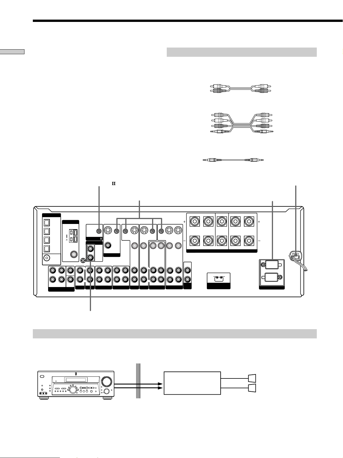
Other Hookups
White (L) White (L)
Red (R) Red (R)
Required cords
Audio cords (not supplied)
When connecting a cord, be sure to match the color-coded pins to the
appropriate jacks on the components.
Audio/video/control S connecting cord (supplied) (1)
Control S connecting cord (supplied) (1)
Black E Black E
Yellow (video) A
White (L/audio) B
Red (R/audio) C
Black (control S) D
Yellow (video) A
White (L/audio) B
Red (R/audio) C
Black (control S) D
SIGNAL GND
DIGITAL
MD/DAT OUT
MD/DAT IN
TV/SAT IN
DVD/LD IN
OPTICAL
COAXIAL
DVD/LD
IN
AUDIO IN AUDIO IN AUDIO OUT
AUDIO
OUT
AUDIO OUTAUDIO IN AUDIO IN
VIDEO OUT
VIDEO IN VIDEO IN VIDEO IN VIDEO IN
FRONT
VIDEO OUT
SWITCHED 120W/1A MAX
AC 120V 60Hz
4
Ω 8Ω
VIDEO OUT
S-VIDEO
OUT
S-VIDEO
OUT
S-VIDEO
IN
S-VIDEO
IN
S-VIDEO
IN
CTRL S
IN
CTRL S
OUT
CTRL S
OUT
CTRL S
STATUS IN
ANTENNA
COAXIAL
FM
75
Ω
SUB
WOOFER
INOUT
TAPE
MONITOR
TV/SAT DVD/LD
VIDEO 2 VIDEO 1
AC OUTLET
IMPEDANCE
SELECTOR
R
L
R
L
R
L
SURROUND CENTER FRONT
IMPEDANCE USE 8 – 16Ω IMPEDANCE USE 4 – 16Ω
R
L
R
L
SPEAKERS
R
L
SUB
WOOFER
MULTI CH IN
FRONT SURROUND
CENTER
IN INOUT
CD/SACD
IN
PHONO
R
L
R
L
MD/DAT
CONTROL A1
2ND ROOM
AM
U
R
L
CTRL S (STATUS) IN/OUT
CONTROL A1
AC OUTLET
b
AUDIO
OUT
AUDIO
IN
SPEAKERS
L
R
2ND ROOM
? / 1
DISPLAY
DIMMER
ON SCREEN
MEMORY SHIFT FM MODE FM AM
PRESET
TUNING
TUNING
–
+
–
+
MULTI CHANNEL DECODING
A.F.D.
SOUND FIELD
MULTI /2CH A. DIRECT
DIGITAL CONCERT HALL
EQUALIZER
MUTING
INPUT MODE
MODE
2ND ROOM
FUNCTION
6.1 CH DECODING
CINEMA STUDIO EX
AA
MODE 2CH
PHONES
VIDEO 3 INPUT
VIDEO L AUDIO R
SPEAKERS
EQ
SURR
LEVEL
SET UP
NAME
ENTER
BBC
MASTER VOLUME
+
–
AC power cord
To a wall outlet
Example of a 2nd room hookup using the 2ND ROOM jacks (STR-DE975 only)
You can use the 2ND ROOM jacks to output the audio signal of the selected component to a stereo amplifier located in
another room. Press 2ND ROOM repeatedly to switch the audio signal output to the 2nd room.
Speaker (L)
Speaker (R)
Main room
Stereo amplifier
2nd room
2ND ROOM
(STR-DE975 only)
Note
This function is not available when MULTI CH IN is selected.
13
Hooking Up the Components
AUDIO
OUT
OUT IN
S-LINK
VIDEO
IN
IN
S-LINK
VIDEO
OUT
AUDIO
OUT
OUTPUT
IN
S-LINK
VIDEO
OUT
AUDIO
OUT
OUTPUT
AUDIO IN AUDIO IN AUDIO OUT AUDIO IN
VIDEO OUT
VIDEO IN VIDEO IN VIDEO INVIDEO OUT
S-VIDEO
OUT
S-VIDEO
OUT
S-VIDEO
IN
S-VIDEO
IN
S-VIDEO
IN
CTRL S
IN
CTRL S
OUT
CTRL S
OUT
CTRL S
STATUS IN
MONITOR
TV/SAT DVD/LD
VIDEO 1
R
L
R
L
*
*
****
A
DE
B
C
TV
Receiver
S-LINK CONTROL S hookup
If you have a S-LINK CONTROL S-compatible Sony TV,
satellite tuner, monitor, DVD player or VCR, use an
audio/video/control S connecting cord (supplied) or a
control S connecting cord (supplied) to connect the CTRL
S (STATUS) IN (for TV, satellite tuner, or monitor) or OUT
(for VCR, etc.) jack on the receiver to the appropriate S-
LINK jack on the respective component. Refer to the
operating instructions supplied with your TV, satellite
tuner, monitor, VCR, etc., for details.
The following illustration is an example of S-LINK
CONTROL S hookups between the receiver, a TV, a VCR,
and a DVD player. When your TV is connected to the
receiver as shown below, the TV input mode will change
to video input whenever you turn on the receiver. When
you connect the receiver as shown below, input mode of
the receiver changes to VIDEO 1 or DVD/LD whenever
you play your VCR or DVD.
The following connections also change the input mode of
the receiver to TV whenever you operate your TV.
VCR 1
DVD
player
CONTROL A1 hookup
• If you have a CONTROL A1 compatible Sony
CD player, SACD player, tape deck, or MD deck
Use a CONTROL A1 cord (not supplied) to connect the
CONTROL A1
jack on the CD player, SACD player,
tape deck, or MD deck to the CONTROL A1
jack on
the receiver. Refer “CONTROL-A1
Control System”
on page 53 and the operating instructions supplied with
your CD player, SACD player, tape deck, or MD deck
for details.
Note
If you make CONTROL A1 connections from the receiver to
an MD deck that is also connected to a computer, do not
operate the receiver while using the “Sony MD Editor”
software. This may cause a malfunction.
• If you have a Sony CD changer with a
COMMAND MODE selector
If your CD changer’s COMMAND MODE selector can
be set to CD 1, CD 2, or CD 3, be sure to set the
command mode to “CD 1” and connect the changer to
the CD jacks on the receiver.
If, however, you have a Sony CD changer with VIDEO
OUT jacks, set the command mode to “CD 2” and
connect the changer to the VIDEO 2 jacks on the
receiver.

14
Hooking Up the Components
Digital Component Hookups
Connecting the AC power cord
Before connecting the AC power cord of this receiver to a
wall outlet:
• Connect the speaker system to the receiver (see page
16).
Connect the AC power cord(s) of your audio/video
components to a wall outlet.
If you connect other audio/video components to the AC
OUTLET(s) on the receiver, the receiver will supply power
to the connected component(s), allowing you to turn the
whole system on or off when you turn the receiver on or
off.
Caution
Make sure that the total power consumption of the component(s)
connected to the receiver’s AC OUTLET(s) does not exceed the
wattage stated on the rear panel. Do not connect high-wattage
electrical home appliances such as electric irons, fans, or TVs to
this outlet.
15
Hooking Up and Setting Up the Speaker System
? / 1
DISPLAY
DIMMER
ON SCREEN
MEMORY SHIFT FM MODE FM AM
PRESET
TUNING
TUNING
–
+
–
+
MULTI CHANNEL DECODING
A.F.D.
SOUND FIELD
MULTI /2CH A. DIRECT
DIGITAL CONCERT HALL
EQUALIZER
MUTING
INPUT MODE
MODE
2ND ROOM
FUNCTION
6.1 CH DECODING
CINEMA STUDIO EX
AA
MODE 2CH
PHONES
VIDEO 3 INPUT
VIDEO L AUDIO R
SPEAKERS
EQ
SURR
LEVEL
SET UP
NAME
ENTER
BBC
MASTER VOLUME
+
–
SET UP
Hooking Up
and Setting Up
the Speaker
System
This chapter describes how to hook
up your speaker system to the
receiver, how to position each speaker,
and how to set up your speakers to
enjoy multi channel surround sound.
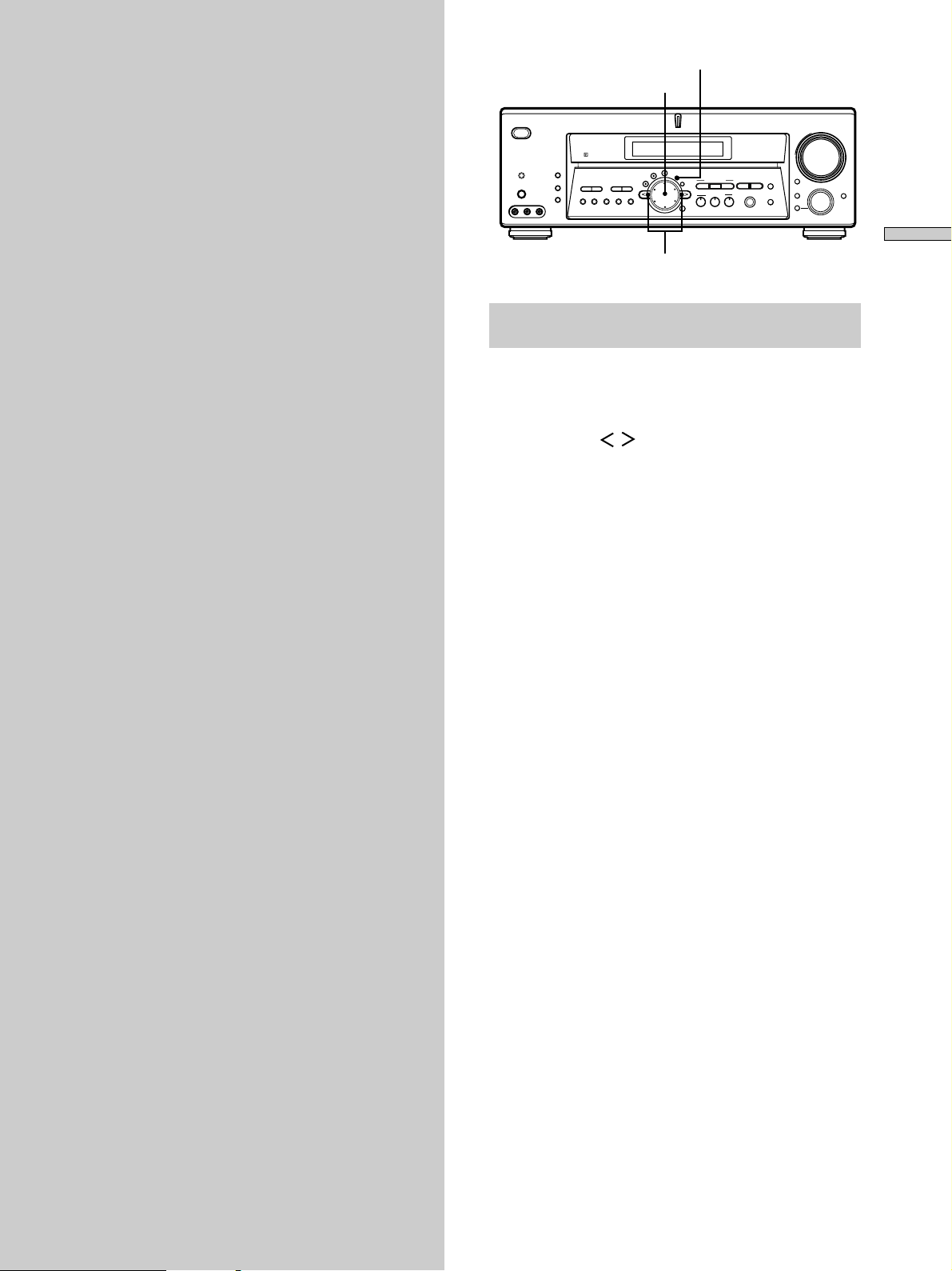
Brief descriptions of buttons and control
used to set up the speaker system
SET UP button: Press to enter the setup mode when
specifying speaker types and distances.
Cursor buttons ( / ): Use to select parameters after
pressing the SET UP button.
Jog dial: Use to adjust the setting of each parameter.
Cursor buttons
Jog dial
16
Hooking Up and Setting Up the Speaker System
SIGNAL GND
DIGITAL
MD/DAT OUT
MD/DAT IN
TV/SAT IN
DVD/LD IN
OPTICAL
COAXIAL
DVD/LD
IN
AUDIO IN AUDIO IN AUDIO OUT
AUDIO
OUT
AUDIO OUTAUDIO IN AUDIO IN
VIDEO OUT
VIDEO IN VIDEO IN VIDEO IN VIDEO IN
FRONT
VIDEO OUT
SWITCHED 120W/1A MAX
AC 120V 60Hz
4
Ω
8
Ω
VIDEO OUT
S-VIDEO
OUT
S-VIDEO
OUT
S-VIDEO
IN
S-VIDEO
IN
S-VIDEO
IN
CTRL S
IN
CTRL S
OUT
CTRL S
OUT
CTRL S
STATUS IN
ANTENNA
COAXIAL
FM
75
Ω
SUB
WOOFER
INOUT
TAPE
MONITOR
TV/SAT DVD/LD
VIDEO 2 VIDEO 1
AC OUTLET
IMPEDANCE
SELECTOR
R
L
R
L
R
L
SURROUND CENTER FRONT
IMPEDANCE USE 8 – 16
Ω
IMPEDANCE USE 4 – 16
Ω
R
L
R
L
SPEAKERS
R
L
SUB
WOOFER
MULTI CH IN
FRONT SURROUND
CENTER
IN INOUT
CD/SACD
IN
PHONO
R
L
R
L
MD/DAT
CONTROL A1
2ND ROOM
AM
U
R
L
}
]
}
]
}
]
}
]
}
]
INPUT
AUDIO
IN
IMPEDANCE
SELECTOR
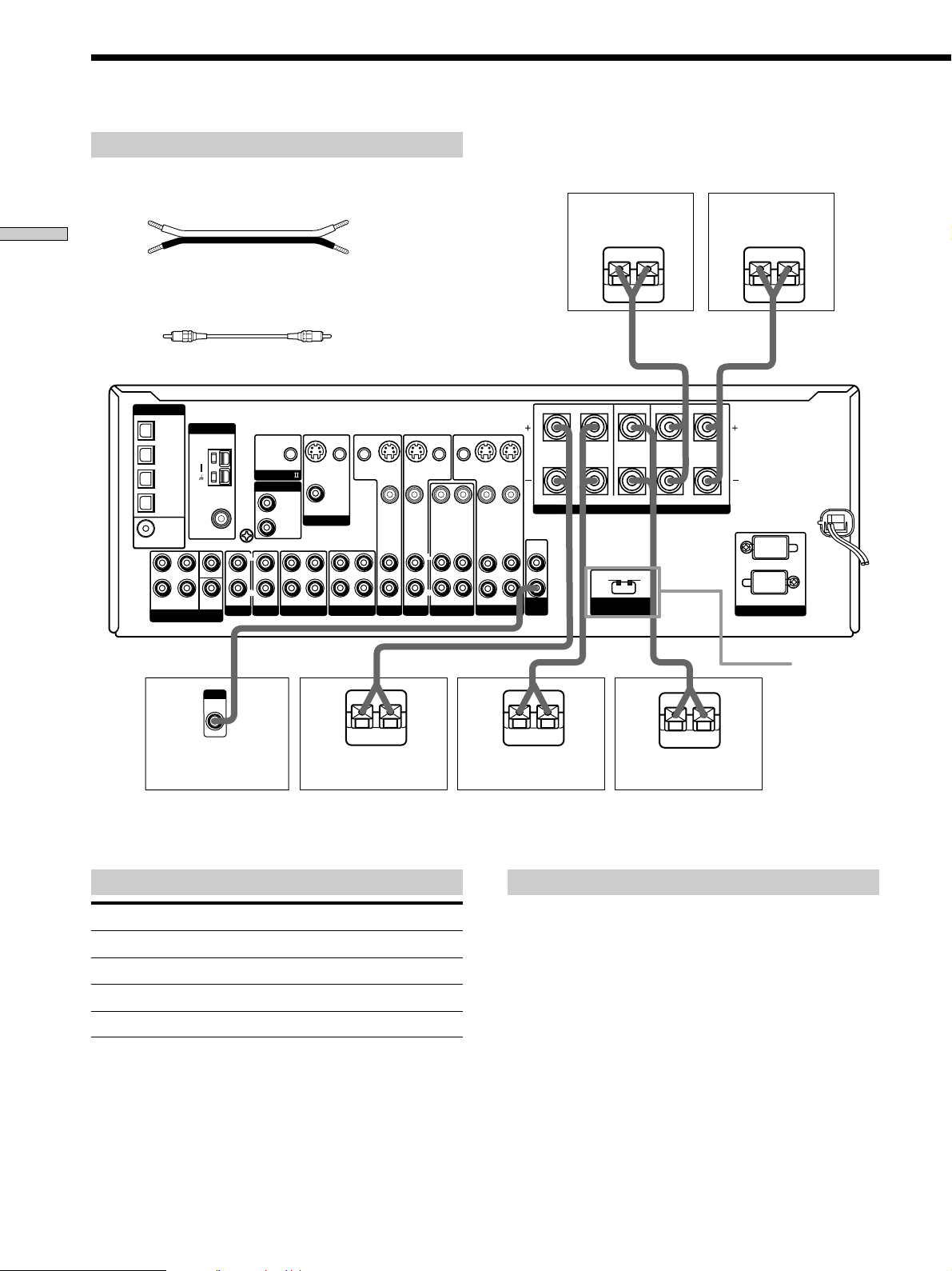
Front speaker (R) Front speaker (L)
Notes on speaker system hookup
• Twist the stripped ends of the speaker cords about 2/3
inch (10 mm). Be sure to match the speaker cord to the
appropriate terminal on the components: + to + and –
to –. If the cords are reversed, the sound will be
distorted and will lack bass.
• If you use speakers with low maximum input rating,
adjust the volume carefully to avoid excessive output
on the speakers.
Terminals for connecting the speakers
Connect the To the
Front speakers (8 or 4** ohm) SPEAKERS FRONT terminals
Surround speakers (8 ohm)
SPEAKERS SURROUND terminals
Center speaker (8 ohm) SPEAKERS CENTER terminals
Active sub woofer***
SUB WOOFER AUDIO OUT jack
** See “Speaker impedance” on the next page.
*** You can connect an active sub woofer to either of the two jacks. The
remaining jack can be used to connect a second active sub woofer.
Required cords
Speaker cords (not supplied)
One for each front, surround, and center speaker
(+) (+)
(–) (–)
Monaural audio cord (not supplied)
One for an active woofer
Black Black
Speaker System Hookup
*
You can connect a surround back speaker.
Active sub woofer Surround speaker (R) Surround speaker (L)
Center speaker*
17
Hooking Up and Setting Up the Speaker System
Speaker impedance
Set the IMPEDANCE SELECTOR for the front speakers as
indicated in the table below. Check the instruction manual
supplied with your speakers if you’re not sure of their
impedance. (This information is usually printed on a label
on the back of the speaker.)
If the nominal impedance of
your speaker is
Between 4 and 8 ohms
8 ohms or higher
Speakers connected to the SURROUND and CENTER
SPEAKERS terminals must have a nominal impedance of
8 ohms or higher (regardless of the setting of the
IMPEDANCE SELECTOR).
Note
Be sure to turn the power off when setting the IMPEDANCE
SELECTOR.
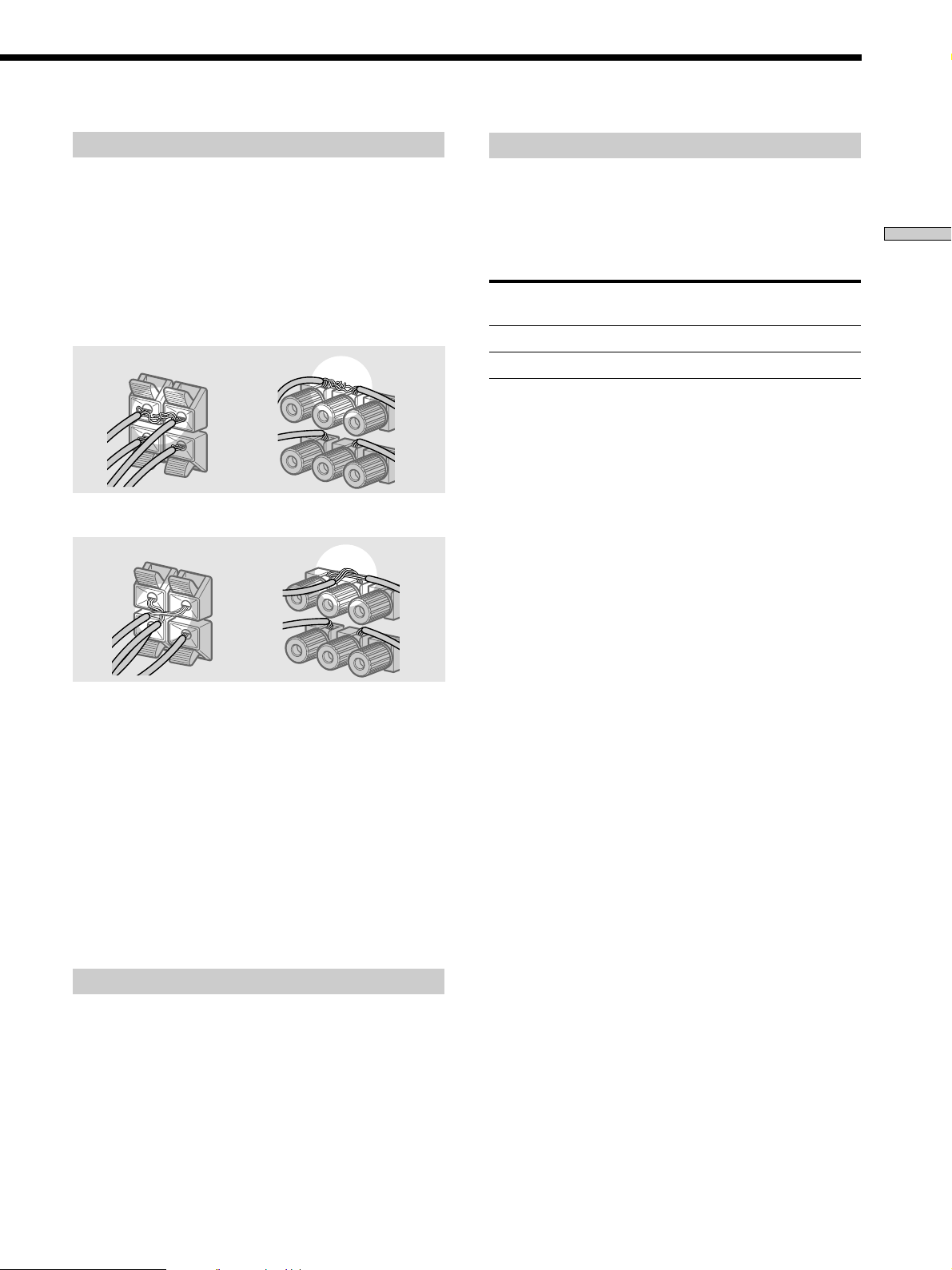
To avoid short-circuiting the speakers
Short-circuiting of the speakers may damage the receiver.
To prevent this, make sure to take the following
precautions when connecting the speakers.
Make sure the stripped ends of each speaker cord
does not touch another speaker terminal or the
stripped end of another speaker cord.
Examples of poor conditions of the speaker cord
Stripped speaker cord is touching another speaker terminal.
Stripped cords are touching each other due to excessive
removal of insulation.
After connecting all the components, speakers,
and AC power cord, output a test tone to check
that all the speakers are connected correctly. For
details on outputting a test tone, see page 23.
If no sound is heard from a speaker while outputting a
test tone or a test tone is output from a speaker other than
the one whose name is currently displayed on the
receiver, the speaker may be short-circuited. If this
happens, check the speaker connection again.
To avoid damaging your speakers
Make sure that you turn down the volume before you
turn off the receiver. When you turn on the receiver, the
volume remains at the level you turn off the receiver.
Set IMPEDANCE SELECTOR to
4Ω
8Ω
18
Hooking Up and Setting Up the Speaker System
Performing Initial Setup Operations
Performing initial setup operations
Before using your receiver for the first time, adjust SET
UP parameters so that the receiver correspond to your
system. For the adjustable parameters, see the table on
page 62. See pages 19 – 23 for speaker settings and pages
51 – 52 for other settings.
1/u
? / 1
DISPLAY
DIMMER
ON SCREEN
MEMORY SHIFT FM MODE FM AM
PRESET
TUNING
TUNING
–
+
–
+
MULTI CHANNEL DECODING
A.F.D.
SOUND FIELD
MULTI /2CH A. DIRECT
DIGITAL CONCERT HALL
EQUALIZER
MUTING
INPUT MODE
MODE
2ND ROOM
FUNCTION
6.1 CH DECODING
CINEMA STUDIO EX
AA
MODE 2CH
PHONES
VIDEO 3 INPUT
VIDEO L AUDIO R
SPEAKERS
EQ
SURR
LEVEL
SET UP
NAME
ENTER
BBC
MASTER VOLUME
+
–
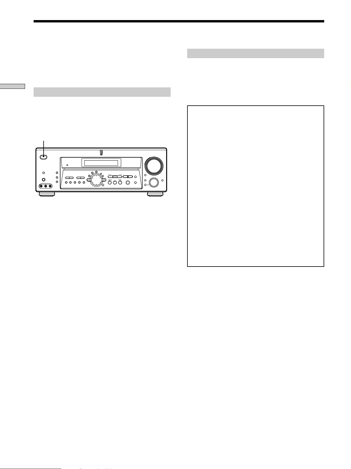
Demonstration Mode
The demonstration will activate the first time you turn on
the power. When the demonstration starts, the following
message appears in the display twice:
“Now Demonstration Mode!! To finish the
demonstration, please press POWER KEY while this
message appears in the display. Thank you!”
To cancel the demonstration
Press ?/1 to turn the receiver off while the above message
is being displayed. The next time you turn the receiver on,
the demonstration will not appear.
To view the demonstration
Hold down SET UP and press ?/1 to turn on the power.
Notes
• Running the demonstration will clear the receiver’s
memory. For details on what will be cleared, see
“Clearing the receiver's memory” on this page.
• You cannot cancel demonstration if you did not press
?/1 while the above message is being displayed. To
cancel demonstration after the above message appears,
press ?/1 twice to activate the demonstration again.
Then, press ?/1 while the above message is being
displayed.
Once you have hooked up the speakers and turned on the
power, clear the receiver’s memory. Then specify the
speaker parameters (size, position, etc.) and perform any
other initial setup operations necessary for your system.
Clearing the receiver’s memory
Before you use your receiver for the first time or when
you want to clear the receiver’s memory, do the following.
This procedure is not necessary if the demonstration
activates when you turn the power on.
1 Turn off the receiver.
2 Hold down ?/1 for five seconds.
The currently selected function, then the
demonstration message appears in the display and the
items including the following are reset or cleared:
• All preset stations are reset or cleared.
• All sound field parameters are reset to their factory
settings.
• All index names (of preset stations and program
sources) are cleared.
• All SET UP parameters are reset to their factory
settings.
• The sound field memorized for each program source
and preset stations are cleared.
• The master volume is set to VOLUME MIN.
19
Hooking Up and Setting Up the Speaker System
45°
90°
20°
A A
B
CC
D
45°
90°
20°
A A
B
CC
D
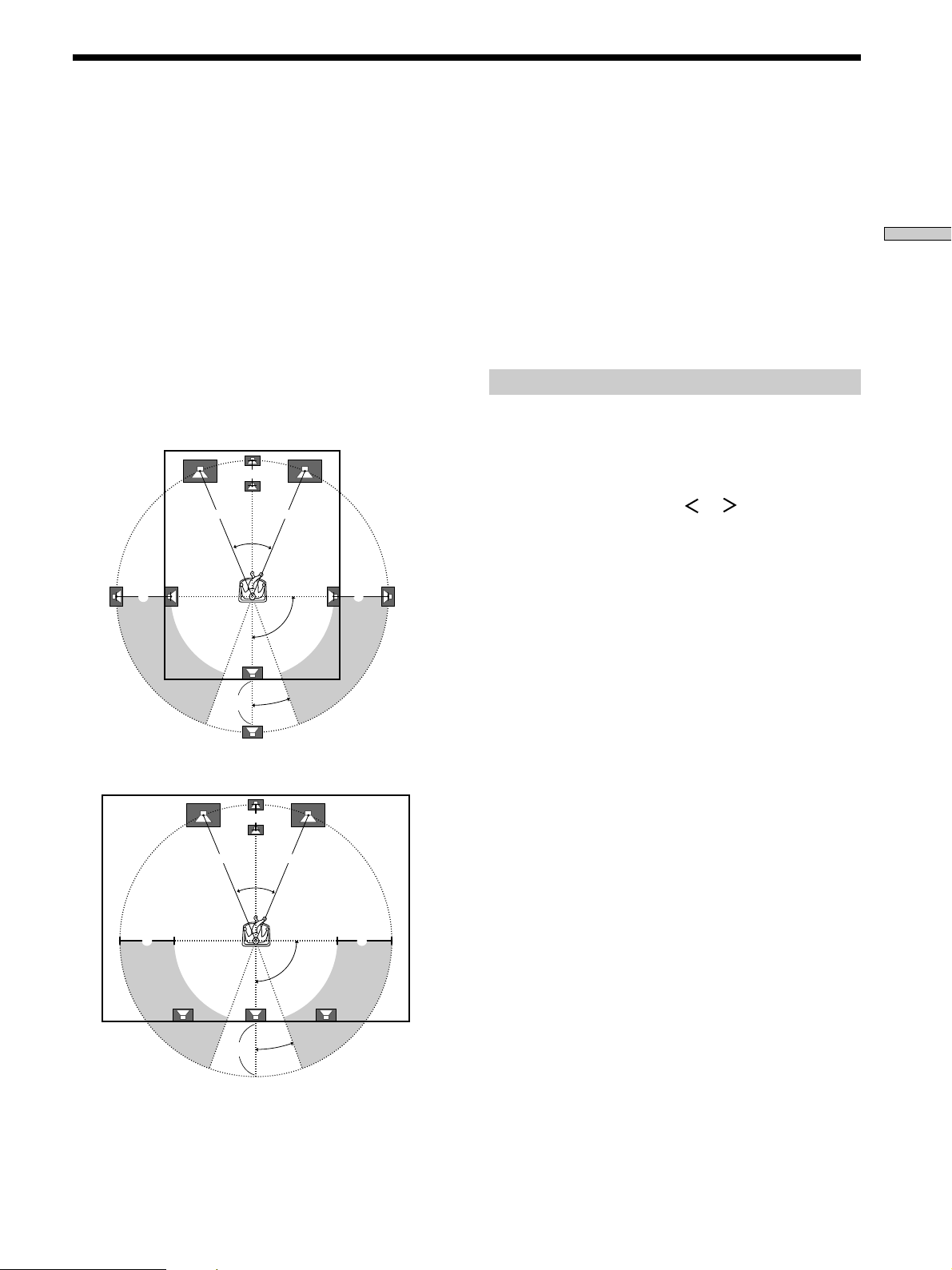
Multi Channel Surround Setup
For the best possible surround sound all speakers should
be the same distance from the listening position (A).
However, this unit lets you to place the center speaker up
to 5 feet (1.5 meters) closer (B) or the surround back
speakers up to 15 feet (4.5 meters) closer (D) and the
surround speakers up to 15 feet (4.5 meters) closer (C) to
the listening position. The front speakers can be placed
from 3 to 40 feet (1.0 to 12.0 meters) from the listening
position (A).
You can place the surround speakers either behind you or
to the side, depending on the shape of your room (etc.).
You can use the center speaker as a surround back
speaker.
When placing surround speakers to your side
When placing the surround speakers behind you
z
When setting up the surround back speaker
Set the speaker at least one meter behind the listening position. It
is recommended to place the speaker at an equal distance from
the surround left or right speakers. If there is no space behind the
listening position, set the speaker above the listening position by
placing it on a stand or hanging it from the ceiling. To prevent
speaker damage or injury in case the speaker falls, make sure that
it is properly fixed in place.
Note
Do not place the center speaker farther away from the listening
position than the front speakers.
Specifying the speaker parameters
1 Press ?/1 to turn on the receiver.
2 Press SET UP.
3 Press the cursor buttons ( or ) to select the
parameter you want to adjust.
4 Turn the jog dial to select the setting you want.
The setting is stored automatically.
5 Repeat steps 3 and 4 until you have set all of the
parameters that follow.

20
Hooking Up and Setting Up the Speaker System
Multi Channel Surround Setup
x Surround back speaker size (SURR BACK)**
Initial setting : NO
This parameter can be set when the center speaker is set to
“NO” and the surround speakers are set to “LARGE” or
“SMALL”.
• If you connect a large speaker that will effectively
reproduce bass frequencies, select “LARGE”. Normally,
select “LARGE”. However, if the front speakers are set
to “SMALL”, you cannot set the surround back speaker
to “LARGE”.
• If the sound is distorted, or you feel a lack of surround
effects when using multi channel surround sound,
select “SMALL” to activate the bass redirection circuitry
and output the center channel bass frequencies from the
front speakers (if set to “LARGE”) or sub woofer.
However, if the surround speakers are set to “SMALL”,
the surround back speaker is automatically set to
“SMALL”.
• If you do not connect a surround back speaker, select
“NO”.
** This parameter is not available when “Surround
speaker size (SURROUND)” is set to “NO”.
z
About speaker sizes (LARGE and SMALL)
Internally, the LARGE and SMALL settings for each speaker
determine whether or not the internal sound processor will cut
the bass signal from that channel. When the bass is cut from a
channel the bass redirection circuitry sends the corresponding
bass frequencies to the sub woofer or other “LARGE” speaker.
However, since bass sounds have a certain amount of
directionality it best not to cut them, if possible. Therefore, even
when using small speakers, you can set them to “LARGE” if you
want to output the bass frequencies from that speaker. On the
other hand, if you are using a large speaker, but prefer not to
have bass frequencies output from that speaker, set it to
“SMALL”.
If the overall sound level is lower than you prefer, set all speakers
to “LARGE”. If there is not enough bass, you can use the
equalizer to boost the bass levels. To adjust the equalizer see page
38.
x Sub woofer selection (SUB WOOFER)
Initial setting : YES
• If you connect a sub woofer, select “YES”.
• If you do not connect a sub woofer, select “NO”. This
activates the bass redirection circuitry and outputs the
LFE signals from other speakers.
• In order to take full advantage of the Dolby Digital
bass redirection circuitry, we recommend setting the sub
woofer’s cut off frequency as high as possible.
x Front speaker size (FRONT)
Initial setting : LARGE
• If you connect large speakers that will effectively
reproduce bass frequencies, select “LARGE”. Normally,
select “LARGE”.
• If the sound is distorted, or you feel a lack of surround
effects when using multi channel surround sound,
select “SMALL” to activate the bass redirection circuitry
and output the front channel bass frequencies from the
sub woofer.
• When the front speaker is set to “SMALL”, the center,
surround and surround back speakers are also
automatically set to “SMALL” (unless previously set to
“NO”).
p Center speaker size (CENTER)
Initial setting : LARGE
• If you connect a large speaker that will effectively
reproduce bass frequencies, select “LARGE”. Normally,
select “LARGE”. However, if the front speakers are set
to “SMALL”, you cannot set the center speaker to
“LARGE”.
• If the sound is distorted, or you feel a lack of surround
effects when using multi channel surround sound,
select “SMALL” to activate the bass redirection circuitry
and output the center channel bass frequencies from the
front speakers (if set to “LARGE”) or sub woofer. *
1
• If you do not connect the center speaker, select “NO”.
The sound of the center channel will be output from the
front speakers.*
2
p Surround speaker size (SURROUND)
Initial setting : LARGE
• If you connect large speakers that will effectively
reproduce bass frequencies, select “LARGE”. Normally,
select “LARGE”. However, if the front speakers are set
to “SMALL”, you cannot set the surround
speakers to
“LARGE”.
• If the sound is distorted, or you feel a lack of surround
effects when using multi channel surround sound,
select “SMALL” to activate the bass redirection circuitry
and output the surround channel bass frequencies from
the sub woofer or other “LARGE” speakers.
• If you do not connect surround
speakers, select “NO”.*
3
z
*1~*3 correspond to the following Dolby Pro Logic modes
*
1
NORMAL
*
2
PHANTOM
*
3
3 STEREO

21
Hooking Up and Setting Up the Speaker System
z
About speaker distances
This receiver allows you to input the speaker position in terms of
distance. However, it is not possible to set the center speaker
farther away than the front speakers. Also, the center speaker can
not be set more that 5 feet (1.5 meters) closer than the front
speakers.
Likewise, the surround
and surround back
speakers cannot be set
farther away from the listening position than the front speakers.
And they can be no more than 15 feet (4.5 meters) closer.
This is because incorrect speaker placement is not conducive to
enjoy the surround sound.
Please note that, setting the speaker distance closer than the
actual location of the speakers will cause a delay in the output of
the sound from that speaker. In other words, the speaker will
sound like it is farther away.
For example, setting the center speaker distance 3~6 feet (1~2 m)
closer than the actual speaker position will create a fairly realistic
sensation of being “inside” the screen. If you cannot obtain a
satisfactory surround effect because the surround speakers are
too close, setting the surround
speaker distance closer (shorter)
than the actual distance will create a larger soundstage.
Adjusting these parameters while listening to the sound often
results in much better surround sound. Give it a try!
x Sub woofer phase polarity (S.W PHASE)
Initial setting : NORMAL
Set the sub woofer phase polarity. There is usually no
problem when the sub woofer phase polarity is set to
“NORMAL”. However, depending on the type of front
speakers, the position of the sub woofer, and the cut-off
frequency of the sub woofer, setting the phase polarity to
“REVERSE” may produce better bass. Besides bass
reproduction, the richness and tightness of the overall
sound may also be affected. While listening from the main
listening position, select the setting that best suits your
environment.
x Distance unit (DISTANCE UNIT)
Initial setting : feet (meter)
Lets you select either feet or meters as the unit of measure
for setting distances.
x Front speaker distance (FRONT XX.X)
Initial setting : 16 feet (5.0 meter)
Set the distance from your listening position to the front
(left or right) speaker (A on page 19).
x Center speaker distance (CENTER XX.X)
Initial setting : 16 feet (5.0 meter)
Set the distance from your listening position to the center
speaker. Center speaker distance should be set from a
distance equal to the front speaker distance (A on page
19) to a distance 5 feet (1.5 meters) closer to your listening
position (B on page 19). When this range is exceeded, the
display blinks. If you make the setting while the display
blinks, you cannot fully enjoy the surround effect.
x Surround speaker distance (SURROUND XX.X)
Initial setting : 11 feet (3.5 meter)
Set the distance from your listening position to the
surround speaker. Surround speaker distance should be
set from a distance equal to the front speaker distance (A
on page 19) to a distance 15 feet (4.5 meters) closer to your
listening position (C on page 19). When this range is
exceeded, the display blinks. If you make the setting
while the display blinks, you cannot fully enjoy the
surround effect.
x Surround back speaker distance (SURR BACK
XX.X)
Initial setting : 11 feet (3.5 meter)
Set the distance from your listening position to the
surround back speaker. Surround back speaker distance
should be set from a distance equal to the front speaker
distance (A on page 19) to a distance 15 feet (4.5 meters)
closer to your listening position (D on page 19). When
this range is exceeded, the display blinks. If you make the
setting while the display blinks, you cannot fully enjoy
the surround effect.
x Sub woofer distance (SUB WOOFER XX.X)
Initial setting : 16 feet (5.0 meter)
Set the distance from your listening position to the sub
woofer.
22
Hooking Up and Setting Up the Speaker System
Multi Channel Surround Setup
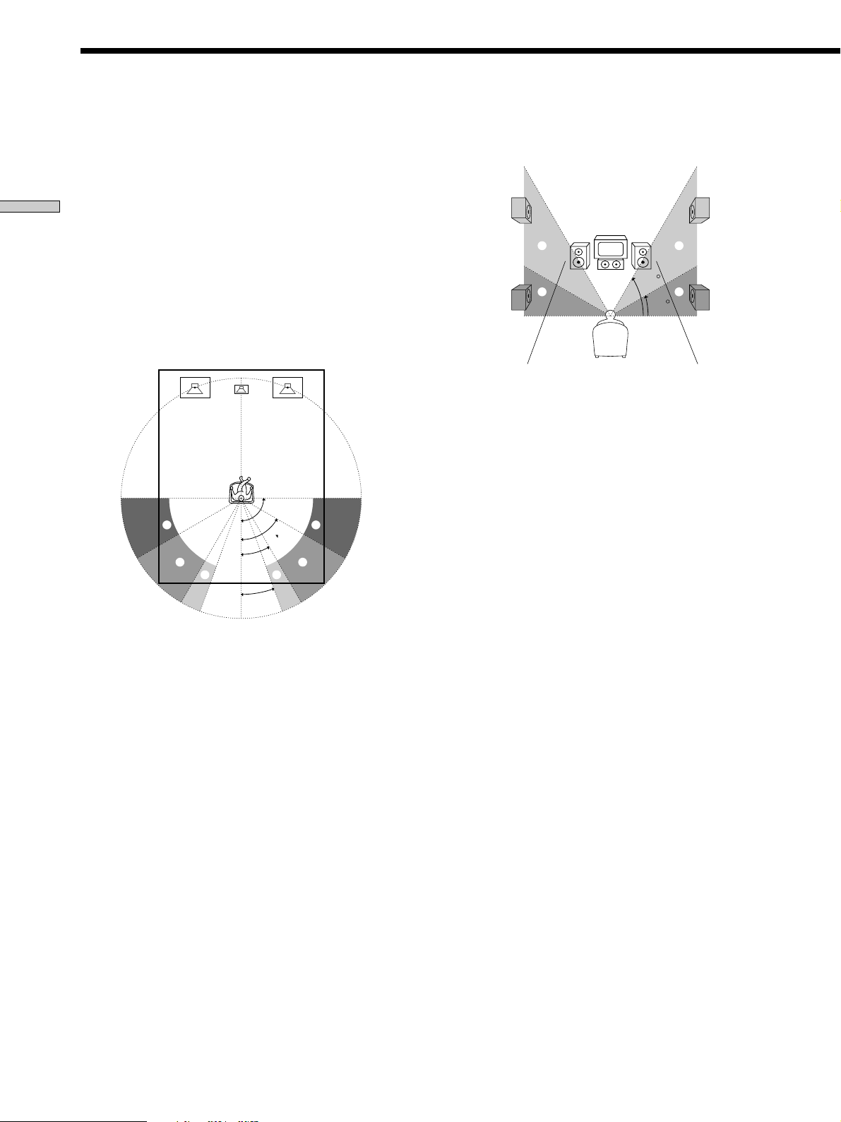
x Surround speaker position (SURR POSI.)*
Initial setting : SIDE
This parameter lets you specify the location of your
surround speakers for proper implementation of the
Digital Cinema Sound surround modes in the
“VIRTUAL” sound fields. Refer to the illustration below.
• Select “SIDE” if the location of your surround speakers
corresponds to section A.
• Select “MIDDLE” if the location of your surround
speakers corresponds to section B.
• Select “BEHIND”** if the location of your surround
speakers corresponds to section C.
This setting only affects the surround modes in the
“VIRTUAL” sound fields.
* These parameters are not available when “Surround
speaker size” is set to “NO”.
** This parameter is only available when “Surround back
speaker size” is set to “NO”.
x Surround speaker height (SURR HEIGHT)*/
Surround back speaker height (SURR BACK
HGT.)***
Initial setting : LOW
This parameter lets you specify the height of your
surround and surround back speakers for proper
implementation of the Digital Cinema Sound surround
modes in the “VIRTUAL” sound fields. Refer to the
illustration below.
• Select “LOW” if the location of your surround speakers
corresponds to section A.
• Select “HIGH” if the location of your surround speakers
corresponds to section B.
60
30
A
B
A
B
This setting only affects the surround modes in the
“VIRTUAL” sound fields.
* These parameters are not available when “Surround
speaker size“ is set to “NO”.
*** This parameter is not available when “Surround back
speaker size” is set to “NO”.
z
About the surround speaker position (SIDE, MIDDLE and
BEHIND)
This setting is designed specifically for implementation of the
Digital Cinema Sound modes in the “VIRTUAL” sound fields.
With the Digital Cinema Sound modes, speaker position is not as
critical as other modes. All of the modes in the “VIRTUAL”
sound fields were designed under the premise that the surround
speaker would be located behind the listening position, but
presentation remains fairly consistent even with the surround
speakers positioned at a rather wide angle. However, if the
speakers are pointing towards the listener from the immediate
left and right of the listening position, the “VIRTUAL” sound
fields will not be effective unless the surround speaker position
parameter is set to “SIDE”.
Nevertheless, each listening environment has many variables,
such as wall reflections, and you may obtain better results using
“BEHIND” or “MIDDLE” if your speakers are located high above
the listening position, even if they are to the immediate left and
right.
Therefore, although it may result in a setting contrary to the
“Surround speaker position” explanation, we recommend that
you playback multi channel surround encoded software and
listen to the effect each setting has on your listening environment.
Choose the setting that provides a good sense of spaciousness
and that best succeeds in forming a cohesive space between the
surround sound from the surround speakers and the sound from
the front speakers. If you are not sure which sounds best, select
“BEHIND” and then use the speaker distance parameter and
speaker level adjustments to obtain proper balance.
60°
90°
20°
A
B
30°
B
C C
A

23
Hooking Up and Setting Up the Speaker System
3 To change the test tone mode, press the cursor
buttons (
or ) to select the mode you want.
Mode The test tone output
NORMAL The test tone is output from each
speaker in sequence.
PHASE The test tone is output from two
speakers at a time in sequence.
(There is no sound output from
the sub woofer.)
You can also adjust the balance
between speakers.
2CH SWAP You can adjust the speaker levels
while listening to the source (not
the test tone). Turn on the
connected component, start
playing, then turn FUNCTION to
select the component (except
connected to the MULTI CH IN
jacks).
The sound for the front L/R
speakers is output from the
surround R/L speakers. You can
adjust the level of surround
speakers from the listening
position.
Note
You cannot select “2CH SWAP” when “2CH A. DIRECT” is
selected (qh on page 28).
4 Adjust the LEVEL parameters so that the level of
the test tone from each speaker sounds the same
when you are in your main listening position.
Press LEVEL to adjust the balance and level of
speakers. For details on the LEVEL menu, see page 37.
While adjusting, the test tone is output from the
speaker whose adjustment is performed.
5 Press TEST TONE again to turn off the test tone.
Tip
You can adjust the level of the all speakers at the same time. Turn
MASTER VOLUME on the main unit or press MASTER VOL +/–
on the remote.
Notes
• The adjusted value are shown in the display during
adjustment.
• Although these adjustments can also be made via the front
panel using the LEVEL menu (when the test tone is output, the
receiver switches to the LEVEL menu automatically), we
recommend you to follow the procedure described above and
adjust the speaker levels from your listening position using the
remote.
x Front speaker crossover frequency
(FRONT SP > XXX Hz)
Initial setting : STD (120Hz)
Lets you adjust the front speaker bass crossover frequency
when the front speakers are set to “SMALL”.
x Center speaker crossover frequency
(CENTER SP > XXX Hz)
Initial setting : STD (120 Hz)
Lets you to adjust the center speaker bass crossover
frequency when the center speaker is set to “SMALL”.
x Surround speaker crossover frequency
(SURROUND SP > XXX Hz)
Initial setting : STD (120 Hz)
Lets you adjust the surround speaker bass crossover
frequency when the surround speakers are set to
“SMALL”.
x Surround back crossover frequency (SURR
BACK SP > XXX Hz)
Initial setting : STD (120 Hz)
Lets you adjust the surround back speaker bass crossover
frequency when the surround back speaker is set to
“SMALL”.
x LFE high cut filter (LFE HIGH CUT > XXX Hz)
Initial setting : STD (120 Hz)
Lets you select the cut off frequency of the LFE channel
high cut filter. Normally, select “STD”. When using a
passive subwoofer powered by a separate power
amplifier, it may be better to change the cut off frequency.
When this is the case, use a setting other than STD.
Adjusting the speaker level
Use the remote while seated in your listening position to
adjust the level of each speaker.
Note
This receiver incorporates a new test tone with a frequency
centered at 800 Hz for easier speaker level adjustment.
1 Press ?/1 to turn on the receiver.
2 Press TEST TONE on the remote.
“TEST TONE” appears in the display and you will
hear the test tone from each speaker in sequence.
24
Hooking Up and Setting Up the Speaker System
There’s no sound from a specific component.
, Check that the component is connected correctly to
the audio input jacks for that component.
, Check that the cord(s) used for the connection is
(are) fully inserted into the jacks on both the
receiver and the component.
No sound is heard from one of the front
speakers.
, Connect a pair of headphones to the PHONES jack
to verify that sound is output from the headphones
(see “wh SPEAKERS button” and “PHONES jack”
on page 29).
If only one channel is output from the headphones,
the component may not be connected to the
receiver correctly. Check that all the cords are fully
inserted into the jacks on both the receiver and the
component.
If both channels are output from the headphones,
the front speaker may not be connected to the
receiver correctly. Check the connection of the front
speaker which is not outputting any sound.
If you encounter a problem that is not included above, see
“Troubleshooting” on page 55.
Checking the connections
After connecting all of your components to the receiver,
do the following to verify that the connections were made
correctly.
1 Press ?/1 to turn on the receiver.
2 Turn on the component that you connected (e.g.,
CD player or tape deck).
3 Rotate FUNCTION to select the component
(program source) and start playing it.
4 Rotate MASTER VOLUME to turn up the volume.
If you do not obtain normal sound output after
performing this procedure, look for the reason in the
following checklist and take the appropriate measures to
correct the problem.
There is no sound no matter which component is
selected.
, Check that both the receiver and all components
are turned on.
, Check that the volume level on the display is not
set to VOLUME MIN by turning the MASTER
VOLUME.
, Press SPEAKERS button if SP. OFF appears on the
display.
, Check that all speaker cords are connected
correctly.
, Press MUTING if MUTING appears on the display.
, Check that the headphones are not connected to
the PHONES jack. No sound will come from the
speakers if the headphones are connected.
, Check that the receiver is not in “Demonstration
Mode” (see page 18).
Before You Use Your Receiver
? / 1
DISPLAY
DIMMER
ON SCREEN
MEMORY SHIFT FM MODE FM AM
PRESET
TUNING
TUNING
–
+
–
+
MULTI CHANNEL DECODING
A.F.D.
SOUND FIELD
MULTI /2CH A. DIRECT
DIGITAL CONCERT HALL
EQUALIZER
MUTING
INPUT MODE
MODE
2ND ROOM
FUNCTION
6.1 CH DECODING
CINEMA STUDIO EX
AA
MODE 2CH
PHONES
VIDEO 3 INPUT
VIDEO L AUDIO R
SPEAKERS
EQ
SURR
LEVEL
SET UP
NAME
ENTER
BBC
MASTER VOLUME
+
–
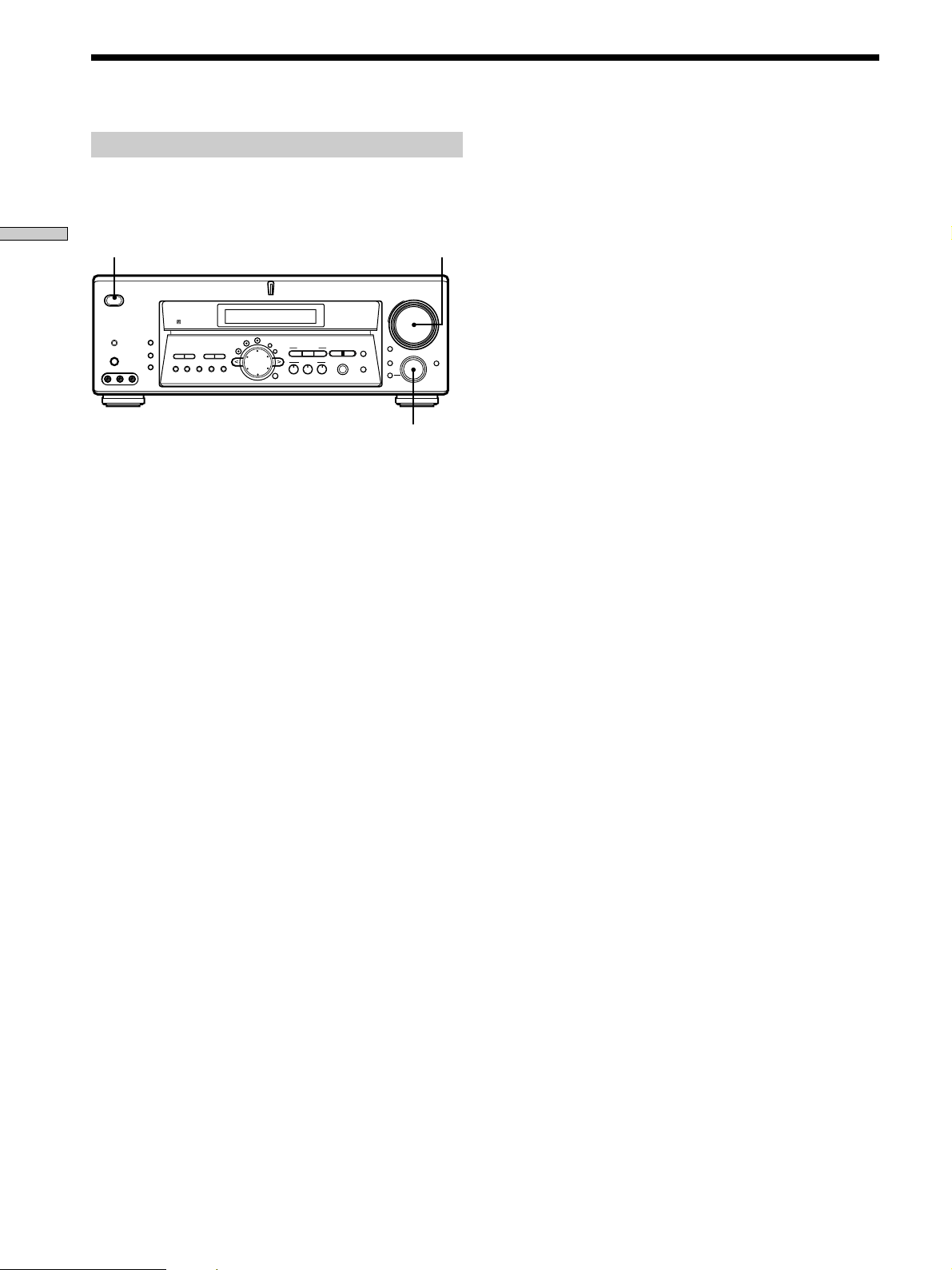
MASTER VOLUME
FUNCTION
1/u

25
Location of Parts and Basic Operations
Location of
Parts and Basic
Operations
This chapter provides information
about the locations and functions of
the buttons and controls on the front
panel. It also explains basic
operations.
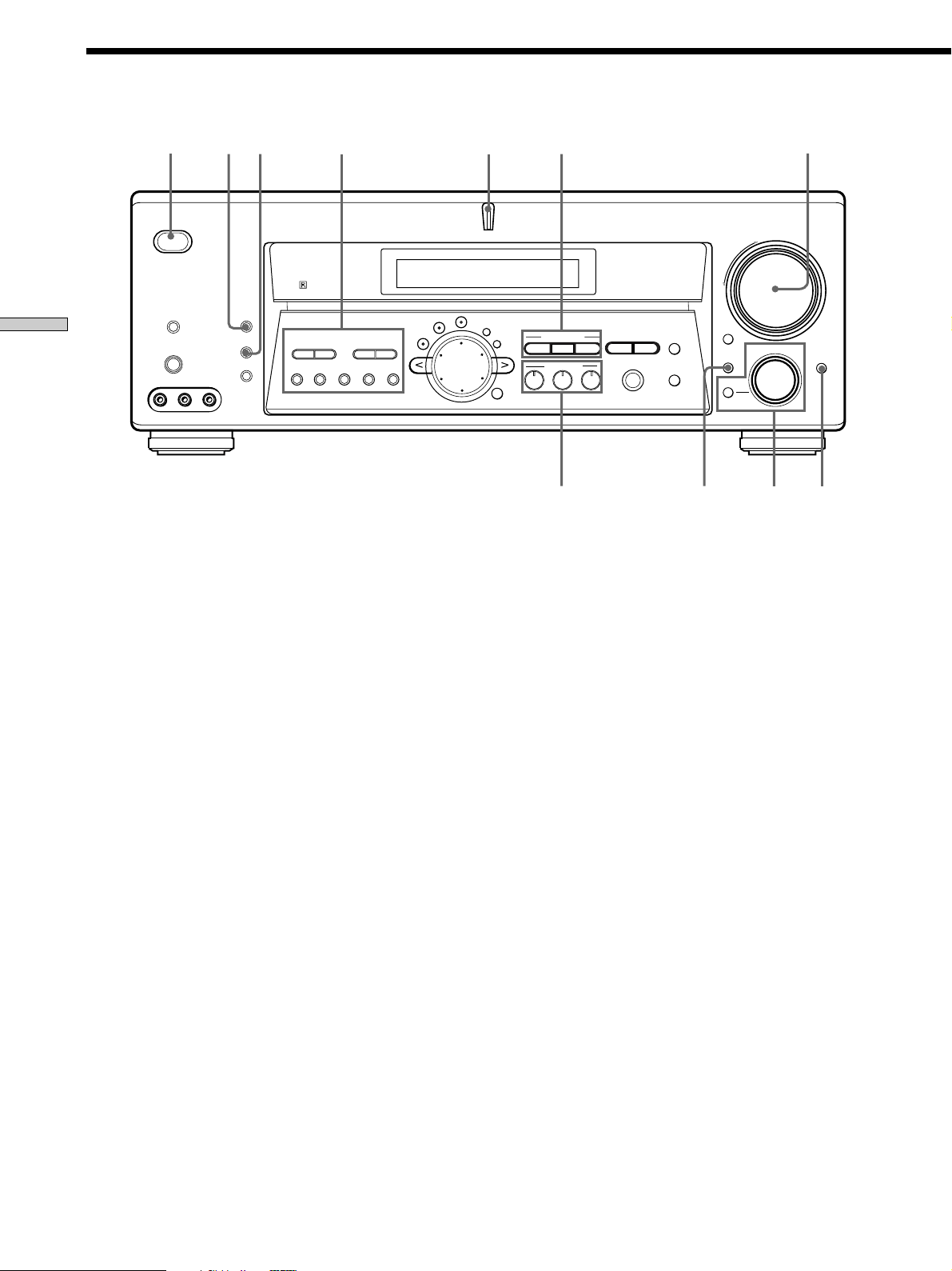
v
Front Panel Parts
Descriptions
1 ?/1 switch
Press to turn the receiver on and off.
2 DISPLAY button
Press repeatedly to change the information on the
display window as follows:
Index name of the component or the preset station*
v
FUNCTION button indication or frequency**
v
Sound field applied to the program source
* Index name appears only when you have assigned one to the
component or preset station (see page 49). Index name does not
appear when only blank spaces have been entered, or it is the
same as the function button.
** Frequency appears only when the tuner is selected.
3 DIMMER button
Press DIMMER repeatedly to adjust the brightness of
the display (5 steps).
When set to the dimmest setting, the display and the
blue LED are turned off. However, when you press
any button, the display becomes the brightest setting
temporary.
26
Location of Parts and Basic Operations
Front Panel Parts Description
? / 1
DISPLAY
DIMMER
ON SCREEN
MEMORY SHIFT FM MODE FM AM
PRESET
TUNING
TUNING
–
+
–
+
MULTI CHANNEL DECODING
A.F.D.
SOUND FIELD
MULTI /2CH A. DIRECT
DIGITAL CONCERT HALL
EQUALIZER
MUTING
INPUT MODE
MODE
2ND ROOM
FUNCTION
6.1 CH DECODING
CINEMA STUDIO EX
AA
MODE 2CH
PHONES
VIDEO 3 INPUT
VIDEO L AUDIO R
SPEAKERS
EQ
SURR
LEVEL
SET UP
NAME
ENTER
BBC
MASTER VOLUME
+
–
0
1
23 4 5
8
6
7
qa
9
4
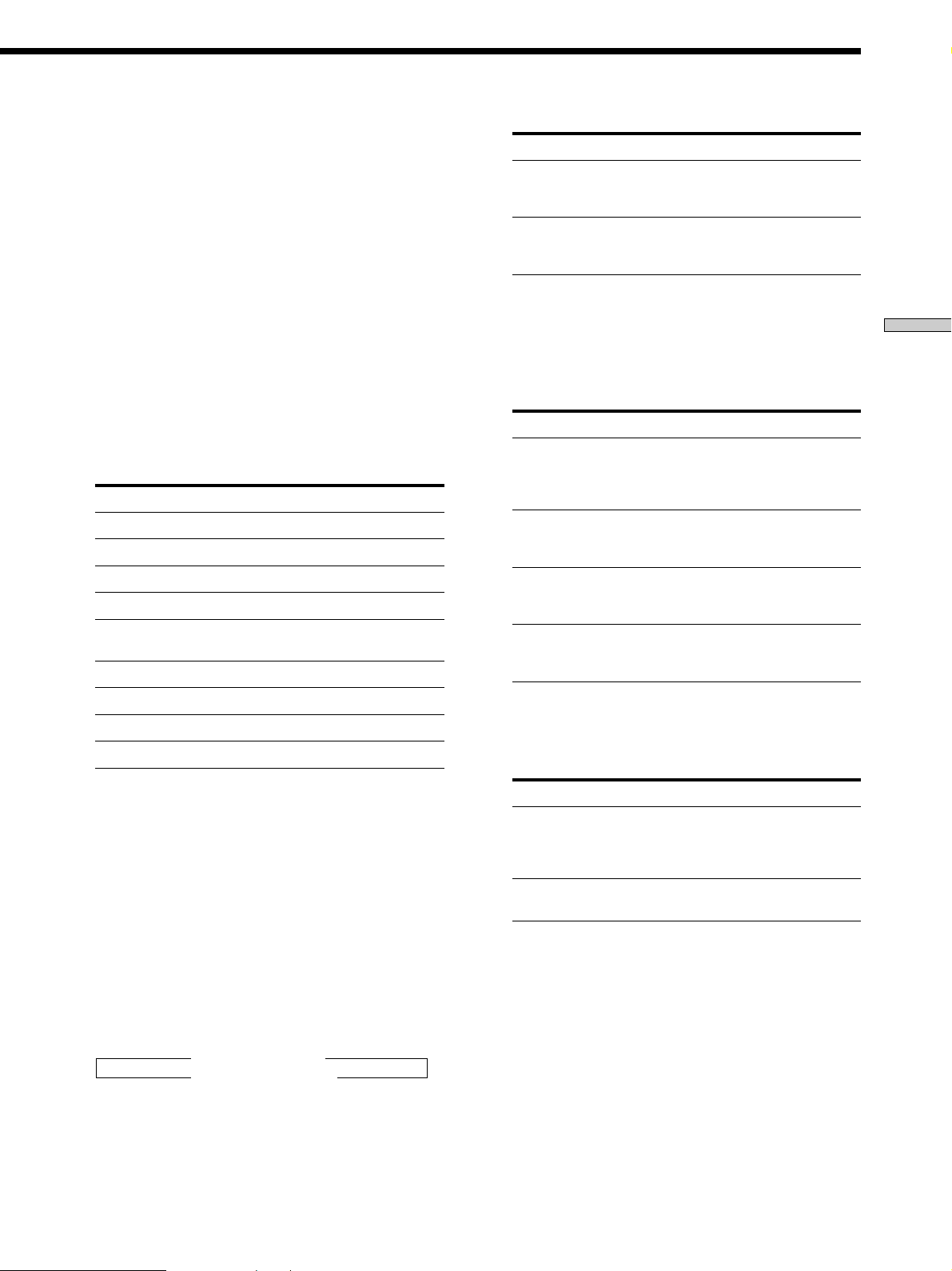
The following buttons operate the built-in tuner. For
details, see “Receiving Broadcasts” starting from page 44.
PRESET TUNING +/– buttons
Scan all preset stations.
TUNING +/- buttons
Scan all the available radio stations.
MEMORY button
Press to memorize a preset station.
SHIFT button
Selects a memory page for preset stations.
FM MODE button
If “STEREO” flashes in the display and the FM stereo
reception is poor, press this button. You will not have
the stereo effect but the sound is improved.
FM button
Selects the FM band.
AM button
Selects the AM band.
5 MULTI CHANNEL DECODING indicator
This indicator lights up when the unit is decoding
signals recorded in a multi channel format.
6 Use the CINEMA STUDIO EX buttons to enjoy the
CINEMA STUDIO EX sound effects.
A/B/C buttons
Press to activate the CINEMA STUDIO EX A, B or C
sound field (page 32).
7 Use the SOUND FIELD buttons to enjoy surround
sound. For details, see “Enjoying Surround Sound”
starting from page 30.
A.F.D. button / indicator
Press to set the receiver to automatically detect the
type of audio signal being input and perform proper
decoding (if necessary).
MODE button / indicator
Press to activate the sound field selection mode (page
31).
2CH button / indicator
Press to output sound from only the front (left and
right) speakers.
8 MASTER VOLUME control
After turning on the component you selected, rotate to
adjust the volume.
27
Location of Parts and Basic Operations
Press MODE to display And rotate FUNCTION to select
V:XXX Any video source to enjoy with
the audio from the selected
component
A:XXX Any audio source to enjoy with
the video from the selected
component
qa INPUT MODE button
Press INPUT MODE to select the input mode for your
digital components. Each time you press the button,
the input mode of the currently selected component
switches.
Select To
AUTO 2CH Give priority to the analog audio
signals input to the AUDIO IN
(L/R) jacks when there is no
digital signals.
COAXIAL FIXED Specify the digital audio signals
input to the DIGITAL COAXIAL
input jacks.
OPTICAL FIXED Specify the digital audio signals
input to the DIGITAL OPTICAL
input jacks.
ANALOG 2CH FIXED Specify the analog audio signals
input to the AUDIO IN (L/R)
jacks.
When the MULTI CH is assigned to a specific function
using SET UP menu (page 51), “AUTO MULTI CH”
and “MULTI CH FIXED” are displayed instead of
“AUTO 2CH” and “ANALOG 2CH FIXED”.
Select To
AUTO MULTI CH Give priority to the analog audio
signals input to the MULTI CH
IN jacks when there is no digital
signals.
MULTI CH FIXED Specify the analog audio signals
input to the MULTI CH IN jacks.
9 2ND ROOM button (STR-DE975 only)
Press repeatedly to select the audio signals for output
to a stereo amplifier or speakers in another room (page
12).
Each press selects another audio source (except
PHONO) to be output from the 2ND ROOM jacks.
“SOURCE” selects the same program source as the
main function controls.
• Even if 2ND ROOM is set to “SOURCE”, the sound from
front speakers (L/R) is not output when the receiver is set
to MULTI CH IN.
• Only signals from components connected to the analog
inputs are output through the 2ND ROOM OUT jacks. No
signals are output from components connected to only the
digital input jacks.
0 FUNCTION control
Rotate to select the component you want to use.
To select Rotate to display
VCR VIDEO 1 or VIDEO 2
Camcorder or video game VIDEO 3 (STR-DE975 only)
DVD or LD player DVD/LD
TV or satellite tuner TV/SAT
Tape deck TAPE (STR-DE975 only)
MD or Tape deck MD/TAPE (STR-DE875 only)
MD or DAT deck MD/DAT (STR-DE975 only)
CD or SACD player CD/SACD
Built in tuner TUNER
Turntable PHONO
After selecting the component, turn on the component
you selected and play the program source.
• After selecting VCR, camcorder, video game, DVD player,
or LD player, turn on the TV and set the TV’s video input
to match the component you selected.
MODE button
Press to select and play another video/audio source in
combination with the selected component.
Each time you press the button, the display changes as
follows:
Standard display
t V:XXX t A:XXX
selected component T
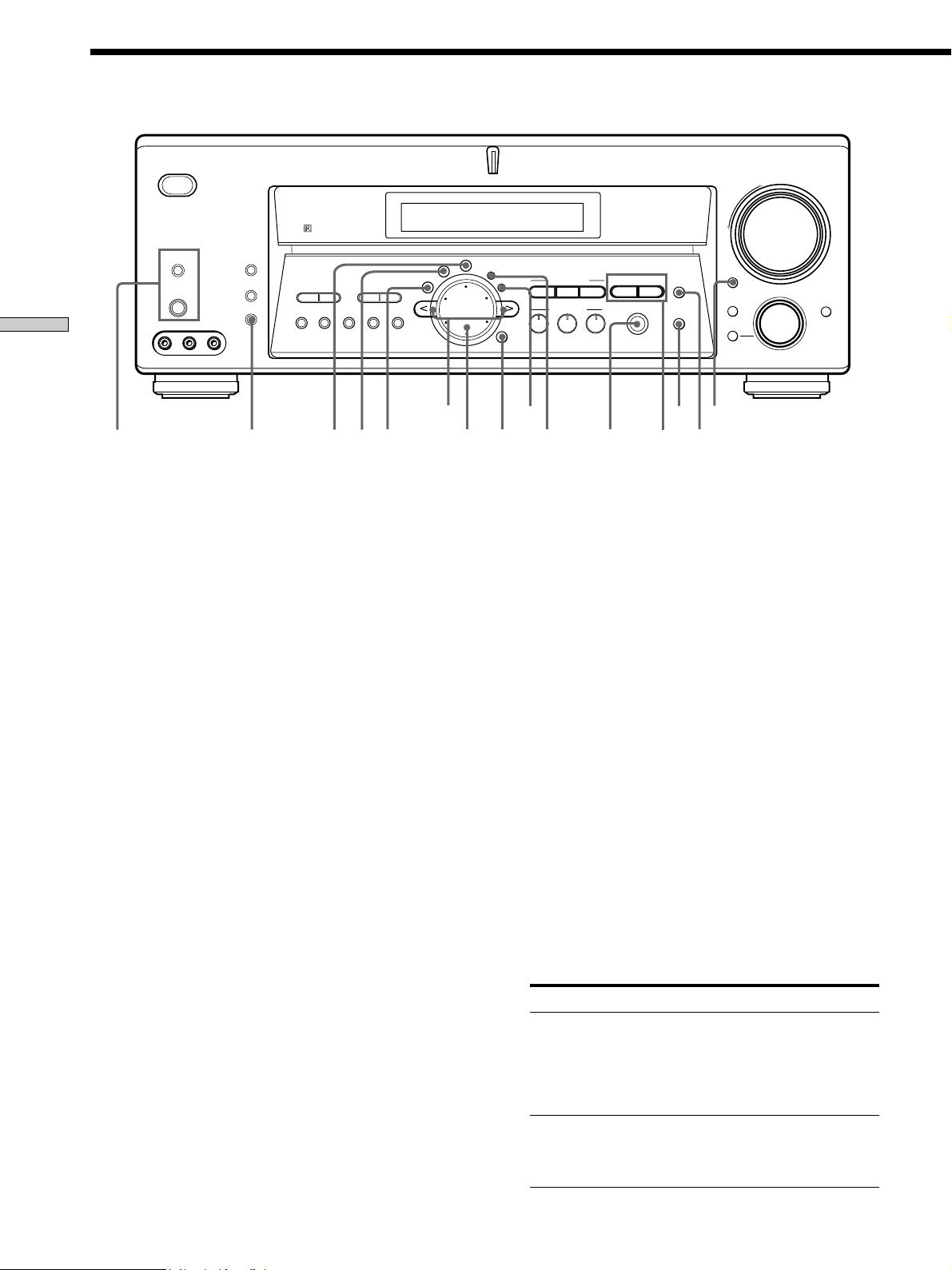
28
Location of Parts and Basic Operations
Front Panel Parts Description
? / 1
DISPLAY
DIMMER
ON SCREEN
MEMORY SHIFT FM MODE FM AM
PRESET
TUNING
TUNING
–
+
–
+
MULTI CHANNEL DECODING
A.F.D.
SOUND FIELD
MULTI /2CH A. DIRECT
DIGITAL CONCERT HALL
EQUALIZER
MUTING
INPUT MODE
MODE
2ND ROOM
FUNCTION
6.1 CH DECODING
CINEMA STUDIO EX
AA
MODE 2CH
PHONES
VIDEO 3 INPUT
VIDEO L AUDIO R
SPEAKERS
EQ
SURR
LEVEL
SET UP
NAME
ENTER
BBC
MASTER VOLUME
+
–
w;
qh
qk
ql
qj
qf
qd
qs
wh
wa
wg wf wswd
qg
qs MUTING button
Press to mute the sound. MUTING appears in the
display when the sound is muted.
qd 6.1 CH DECODING button
Press 6.1 CH DECODING to adjust the 6.1 channel
matrix parameter in the SET UP menu (page 51).
This function works only for the multi channel format
[3/2].
This function is effective for the following sound
fields.
• A.F.D.*
• NORMAL SURROUND
• CINEMA STUDIO EX A-C
• SEMI CINEMA STUDIO EX A-C
• NIGHT THEATER
• MONO MOVIE
• STEREO MOVIE
• V. MULTI DIMENSION
• VIRTUAL MULTI REAR
• V. SEMI M. DIMENSION
• VIRTUAL ENHANCED A, B
* “AUTO” only.
About the “VIRTUAL MATRIX 6.1” playback
Though this receiver incorporates the 5.1 channel amplifier,
you can reproduce the 6.1 channel surround sound of the
sources encoded in 6.1 channel (page 31).
To enjoy “VIRTUAL MATRIX 6.1” playback most effectively,
use the 6.1CH DECODING function when you select
“CINEMA STUDIO EX A-C” or “SEMI CINEMA STUDIO EX
A-C”. The sound characteristics of CINEMA STUDIO and the
3D sound imaging create the virtual surround back speaker,
and you can enjoy the surround effect as if in the real theater.
You can select AUTO/ON/OFF using the 6.1CH DECODING
button (page 51).
qf EQUALIZER button
Press to turn the equalizer on or off. The EQ indicator
in the display lights when the equalizer is turned on.
When you adjust the equalizer using the EQ
parameters (page 38), the settings are stored
automatically and can be reproduced wherever you
turn on the equalizer.
• The equalizer is not compatible with 96 kHz digital audio
signals and during MULTI CH IN input or 2CH ANALOG
DIRECT.
qg DIGITAL CONCERT HALL buttons
Use the DIGITAL CONCERT HALL buttons to enjoy
the DIGITAL CONCERT HALL sound effects.
A/B buttons
Press to activate the DIGITAL CONCERT HALL A or
B sound field (page 32).
qh MULTI/2CH A. DIRECT button
Press MULTI/2CH A. DIRECT to enjoy the audio
source connected to the MULTI CH IN jacks or analog
2 channel input jacks. Only volume control and the
front speaker balance can be adjusted when set to 2CH
ANALOG DIRECT. When set to MULTI DIRECT, you
can adjust balance and level of all the speakers. When
this function is on, the surround effects are turned off.
Select To
MULTI Enjoy the audio source connected
to the MULTI CH IN jacks.
MULTI CH IN indicator lights up
in the display. This mode is
suitable for enjoying high quality
analog source.
2CH A. DIRECT Enjoy the audio source connected
to analog 2 channel jacks. This
mode is suitable for enjoying
high quality analog source.

29
Location of Parts and Basic Operations
qj SET UP button
Press to activate the setup mode, then use the cursor
buttons (wa) to select any of the following indications.
You can then make various settings using the jog dial
(w;). For details, see “Adjustment Using the SET UP
Button” starting from page 51.
qk NAME button
Press to activate the name function and enter names
for preset stations and program sources (page 49).
ql ENTER button
Press to enter individual characters for the preset
station and program source names.
w; Jog dial
Turn to adjust the selected speaker level, surround,
and equalizer parameters (etc.).
wa Cursor buttons (
/ )
Press to select various speaker level, surround, and
equalizer parameters (etc.).
ws EQ button
Press to activate the equalizer parameters (page 38).
The indicator on the button lights up and you can
adjust the various equalizer parameters.
wd SURR button
Press to activate the surround parameters (page 36).
The indicator on the button lights up and you can
adjust the various surround parameters (effect level,
wall type, etc.).
wf LEVEL button
Press to activate the speaker level parameters (page
37). The indicator on the button lights up and you can
adjust the various speaker level parameters (front
balance, surround balance, etc.).
wg ON SCREEN button (STR-DE975 only)
Press to turn the on-screen display on or off (page 8).
Press to display the current sound field, and the
parameters for SURR, LEVEL, EQ, and SET UP. Press
again to turn off the on-screen display.
wh SPEAKERS button
Press SPEAKERS button to ON. Press again to OFF.
PHONES jack
Connects headphones.
• When you connect the headphones, no sound will come
from the speakers and “SP. OFF” lights up in the display.

30
Enjoying
Surround
Sound
This chapter describes how to set up
the receiver to enjoy surround sound.
You can enjoy multi channel surround
when playing back software encoded
with Dolby Digital or DTS.
You can take advantage of surround sound simply by
selecting one of the receiver’s pre-programmed sound
modes. They bring the exciting and powerful sound of
movie theaters and concert halls into your home. You can
also customize the sound modes to obtain the sound you
desire by changing the various surround parameters.
The receiver contains a variety of different sound modes.
The cinema sound modes are designed for use when
playing back movie software (DVD, LD, etc.) encoded
with multi channel surround sound or Dolby Pro Logic.
In addition to decoding the surround sound, some of
these modes also provide sound effects commonly found
in movie theaters.
The virtual sound modes contain compelling applications
of the Sony Digital Cinema Sound digital signal
processing technology. They shift the sound away from
the actual speaker locations to simulate the presence of
several “virtual” speakers.
The music (etc.) sound modes are designed for use with
standard audio sources and TV broadcasts. They add
reverberation to the source signal to make you feel as if
you were in a concert hall or stadium (etc.). Use these
sound modes with two-channel sources like CD and
stereo broadcasts of sports programs or musical concerts.
For more information about the sound modes, see pages
32 – 33.
A.F.D.
The “Auto Format Decoding” sound mode presents the
sound exactly as it was encoded, without adding any
reverberation (etc.).
DCS (Digital Cinema Sound)
The sound fields with DCS marks use DCS technology.
When these sound fields are selected, “Digital Cinema
Sound” indicator in the display lights up.
DCS is the concept name of the surround technology for
home theater developed by Sony. DCS uses the DSP
(Digital Signal Processor) technology to reproduce the
sound characteristics of an actual cinema cutting studio in
Hollywood.
To fully enjoy surround sound, you must register the
number and location of your speakers. See “Multi-
Channel Surround setup” starting on page 19 to set the
speaker parameters before enjoying surround sound.
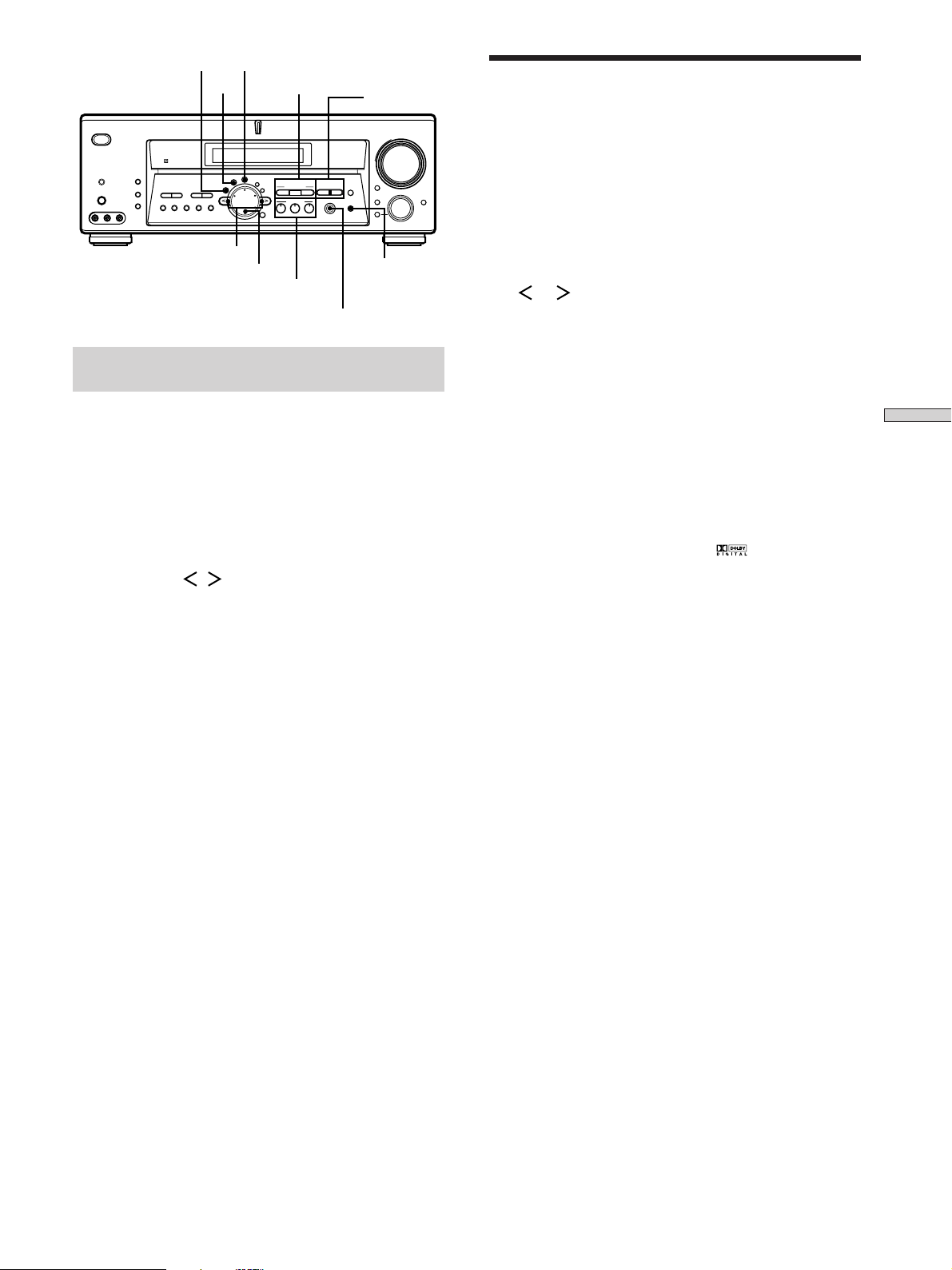
31
Enjoying Surround Sound
Selecting a Sound Field
You can enjoy surround sound simply by selecting one of
the pre-programmed sound fields according to the
program you want to listen to.
1 Press SOUND FIELD MODE.
The current sound field is indicated in the display.
2 Turn the jog dial or press the cursor buttons
(
or ) to select the sound field you want.
See the table starting on page 32 for information on
each sound field.
To turn the sound field off
Press A.F.D., 2CH or MULTI/2CH A. DIRECT (page 33).
Tip
When sound signals with a sampling frequency of 96 kHz are
input, the sound signals are output in stereo automatically, and
the sound field is turned off.
z
You can identify Dolby Surround-encoded software by
looking at the packaging
Dolby Digital discs are labeled with the logo, and Dolby
Surround encoded programs are labeled with the A
logo.
z
6.1 channel matrix decoding
Some movies released after the summer of 1999 added a new
channel to its preexisting 5.1 channel. The new channel added
speakers behind the listening position. In the movie theaters,
these speakers are placed on the rear wall, on each side of the
projection room’s window.
The 6.1 channel system used in the movie theaters is called Dolby
Surround EX system. However, to record on movie films, this 6.1
channel is converted to 5.1 channel using matrix encoding, and
the same number of channels are used as Dolby Digital and DTS
recordings. Recordings on the DVD also use the same signals.
A lot of movie theaters screen movie with matrix encoded
5.1 channel signals and this is not unnatural to the ears. However,
when a matrix decoder is used to create surround center speaker
signals, this simulates the same 6.1 channel sound as Dolby
Surround EX system in the movie theaters.
This unit is equipped with the matrix decoder allowing for 6.1
channel sound production. With Virtual 3D technology, the
surround back signals can be enjoyed even without an actual
surround back speaker. When the center speaker is not used, it is
possible to use this channel to output surround back signals.
Particularly with 6.1 CH DECODING, speakers placed on rear
and side walls in the movie theaters are virtually created. As
reflections and reverberations are also simulated, you can enjoy
powerful sounds as if in the movie theater that uses Dolby
Surround EX system.
Brief descriptions of buttons used to
enjoy surround sound
LEVEL button: Press to customize the level parameters.
SURR button: Press to customize the surround
parameters in the current sound field.
EQ button: Press to customize the equalizer parameters
in the current sound field.
Cursor buttons (
/ ): Use to select parameters after
pressing the LEVEL, SURR, EQ or SET UP buttons.
Jog dial: Use to adjust parameters and select sound fields
(etc.).
SOUND FIELD buttons:
A.F.D. button: Press to set the receiver to
automatically detect the type of audio signal being
input and perform proper decoding (if necessary).
MODE button: Press to activate the sound field
selection mode.
2CH button: Press to output sound from only the
front (left and right) speakers.
EQUALIZER button: Turns the equalizer effect on or off.
CINEMA STUDIO EX buttons: Press to select CINEMA
STUDIO EX A~C sound field.
MULTI/2CH A. DIRECT: Press to input the analog signal
without digital processing. When this function is on, the
equalizer and sound field (etc.) are turned off.
DIGITAL CONCERT HALL buttons: Press to select
DIGITAL CONCERT HALL A~B sound field.
? / 1
DISPLAY
DIMMER
ON SCREEN
MEMORY SHIFT FM MODE FM AM
PRESET
TUNING
TUNING
–
+
–
+
MULTI CHANNEL DECODING
A.F.D.
SOUND FIELD
MULTI /2CH A. DIRECT
DIGITAL CONCERT HALL
EQUALIZER
MUTING
INPUT MODE
MODE
2ND ROOM
FUNCTION
6.1 CH DECODING
CINEMA STUDIO EX
AA
MODE 2CH
PHONES
VIDEO 3 INPUT
VIDEO L AUDIO R
SPEAKERS
EQ
SURR
LEVEL
SET UP
NAME
ENTER
BBC
MASTER VOLUME
+
–
EQUALIZER
CINEMA
STUDIO EX
DIGITAL
CONCERT
HALL
LEVEL
SURR
EQ
Cursor buttons
Jog dial
SOUND FIELD
buttons
MULTI/2CH A. DIRECT

32
Enjoying Surround Sound
Selecting a Sound Field
Sound field information
x NORMAL SURROUND
Software with multi channel surround audio signals is
played back according to the way it was recorded.
Software with 2 channel audio signals is decoded with
Dolby Pro Logic to create surround effects.
x CINEMA STUDIO EX A–C
1)2)
DCS
Uses 3D sound imaging of V. MULTI DIMENSION to
create 5 sets of virtual speakers surrounding the listener
from a single pair of actual surround speakers.
You can reproduce the 6.1 channel surround sound by
creating the virtual surround back speaker through the
“VIRTUAL MATRIX 6.1” playback function (qd on page
28).
• CINEMA STUDIO EX A reproduces the sound
characteristics of Sony Pictures Entertainment’s classic
editing studio.
• CINEMA STUDIO EX B reproduces the sound
characteristics of Sony Pictures Entertainment’s mixing
studio which is one of the most up-to-date facilities in
Hollywood.
• CINEMA STUDIO EX C reproduces the sound
characteristics of Sony Pictures Entertainment’s BGM
recording studio.
x SEMI CINEMA STUDIO EX A–C
1)
DCS
Uses 3D sound imaging of V. SEMI M. DIMENSION to
create 5 sets of virtual speakers surrounding the listener
from the sound of the front speakers (without using actual
surround speakers).
You can reproduce the 6.1 channel surround sound by
creating the virtual surround back speaker through the
“VIRTUAL MATRIX 6.1” playback function (qd on page
28).
• SEMI CINEMA STUDIO EX A reproduces the sound
characteristics of Sony Pictures Entertainment’s classic
editing studio.
• SEMI CINEMA STUDIO EX B reproduces the sound
characteristics of Sony Pictures Entertainment’s mixing
studio which is one of the most up-to-date facilities in
Hollywood.
• SEMI CINEMA STUDIO EX C reproduces the sound
characteristics of Sony Pictures Entertainment’s BGM
recording studio.
x NIGHT THEATER
Allows you to retain a theater like environment while
listening at low volume levels, such as late at night.
x MONO MOVIE
Creates a theater like environment from movies with
monaural soundtracks.
x STEREO MOVIE
Creates a theater like environment from movies recorded
with stereo soundtracks.
x V. MULTI DIMENSION
1)
(Virtual Multi
Dimension)
DCS
Uses 3D sound imaging to create an array of virtual
surround speakers positioned higher than the listener
from a single pair of actual surround speakers. This mode
creates 5 sets of virtual speakers surrounding the listener
at approximately a 30° angle of elevation.
x VIRTUAL MULTI REAR
1)
(Virtual Multi Rear)
DCS
Uses 3D sound imaging to create 3 sets of virtual
surround speakers from 1 set of actual surround speakers.
x V. SEMI M. DIMENSION
1)
(Virtual Semi Multi
Dimension)
DCS
Uses 3D sound imaging to create virtual surround
speakers from the sound of the front speakers without
using actual surround speakers. This mode creates 5 sets
of virtual speakers surrounding the listener at a 30° angle
of elevation.
x VIRTUAL ENHANCED A
1)
(Virtual Enhanced
Surround A)
DCS
Uses 3D sound imaging to create 3 sets of virtual
surround speakers from the sound of the front speakers
without using actual surround speakers.
x VIRTUAL ENHANCED B
1)
(Virtual Enhanced
Surround B)
DCS
Uses 3D sound imaging to create 1 set of virtual surround
speakers from the sound of the front speakers without
using actual surround speakers.
x DIGITAL CONCERT HALL A, B
2)
Reproduces the acoustics of a concert hall using multi-
speaker system and 3D sound imaging for software with 2
channel signals like CDs.
• DIGITAL CONCERT HALL A reproduces the sonic
character of the CONCERTGEBOUW in Amsterdam,
which is famous for its large sound stage due to its
reflectivity.
• DIGITAL CONCERT HALL B reproduces the sonic
character of the MUSIKVEREIN in Vienna, which is
famous for its hall resonance and unique reverberative
sound.
x CHURCH
Reproduces the acoustics of a stone church.
x OPERA HOUSE
Reproduces the acoustics of an opera house.

33
Enjoying Surround Sound
x JAZZ CLUB
Reproduces the acoustics of a jazz club.
x DISCO/CLUB
Reproduces the acoustics of a discotheque/dance club.
x LIVE HOUSE
Reproduces the acoustics of a 300-seat live house.
x ARENA
Reproduces the acoustics of a 1000-seat concert hall.
x STADIUM
Reproduces the feeling of a large open-air stadium.
x GAME
Obtains maximun audio impact from video game
software.
When headphones are connected, you can select the
following sound fields only:
x HEADPHONE (2CH)
Outputs the sound in 2 channel (stereo).
Standard 2 channel (stereo) sources completely bypass the
sound field processing. Multi channel surround formats
are downmixed to 2 channel.
x HEADPHONE (DIRECT)
Outputs the analog signals without digital processing by
the equalizer, sound field, etc.
x HEADPHONE THEATER
Allows you to experience a theater like environment
while listening through a pair of headphones.
1)
“VIRTUAL” sound field: Sound field with virtual speakers.
However, turning the SURROUND menu “VIR. SPEAKERS”
parameter off when using “CINEMA STUDIO EX A~C” or
“SEMI CINEMA STUDIO EX A~C” reproduces the sound
characteristics of each cinema production studio without
virtual speakers.
2)
You can select by pressing the buttons on the front panel.
Notes
• The effects provided by the virtual speakers may cause
increased noise in the play back signal.
• When listening to sound fields that employ the virtual
speakers, you will not be able to hear any sound coming
directly from the surround speakers.
Use the buttons on the front panel to operate the
following modes.
A.F.D. (Auto Format Decoding)
Automatically detects the type of audio signal being input
(Dolby Digital, DTS, Dolby Pro Logic, or standard 2
channel stereo) and performs the proper decoding if
necessary. This mode presents the sound as it was
recorded/encoded, without adding any effects (e.g.
reverberation.)
2CH (2 Channel)
Outputs the sound from the front left and right speakers
only. Standard 2 channel (stereo) sources completely
bypass the sound field processing. Multi channel
surround formats are downmixed to 2 channel.
MULTI/2CH A. DIRECT (Multi/2 CH Analog Direct)
The analog input signal is not digitally processed. You can
enjoy high quality analog source. Only volume control
and the front speaker balance can be adjusted when set to
2CH A. DIRECT. When set to MULTI DIRECT, you can
adjust balance and level of all the speakers. When this
function is on, the equalizer, sound field (etc.) are turned
off.
Note
No sound is output from the sub woofer when the 2 CHANNEL
mode is selected. To listen to two channel (stereo) sources using
the front left and right speakers and a sub woofer, use the AUTO
FORMAT DECODING mode.
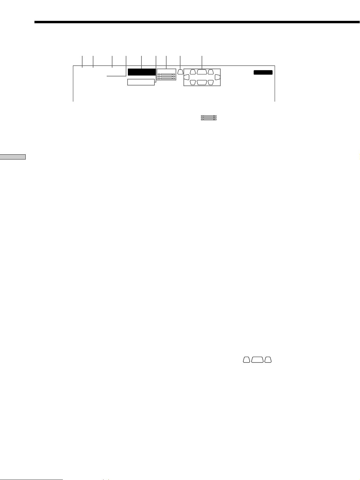
34
Enjoying Surround Sound
PRO LOGIC
EQD.RANGE
OPTCOAXMULTI CH IN
SP.OFF
SLEEP
STEREO MONO
SL
LC
SSB
SR
R
L.F.E.
DTS MPEG
a
1 2 3 5 7 84 6
MEMORY
9
DIGITAL
a
SW
Understanding the Multi-Channel Surround Displays
1 OPT
Lights up when the source signal is a digital signal
being input through the OPTICAL terminal.
2 COAX
Lights up when the source signal is a digital signal
being input through the COAXIAL terminal.
3 MULTI CH IN
Lights up when MULTI CH IN is selected.
4 MPEG
Lights up when MPEG signals are input.
Note
Only the front 2 channels are compatible with MPEG
format. Multi channel surround sound is downmixed
and output from the front 2 channels.
5 ; DIGITAL
This indicator lights up when the receiver is decoding
signals recorded in the Dolby Digital format.
6 PRO LOGIC
Lights up when the receiver applies Pro Logic
processing to two channel signals in order to output
the center and surround channel signals.*
* However, this indicator does not light if the center and surround
speakers are set to “NO”, or the SPEAKERS button is set to
OFF and the A.F.D. or NORMAL SURROUND sound fields
are selected.
Note
Pro Logic decoding does not function for MPEG
format signals.
7
L.F.E.
Lights up when the disc being played back contains
the LFE (Low Frequency Effect) channel. When the
sound of the LFE channel signal is actually being
reproduced, the bars underneath the letters lights up
to indicate the level. Since the LFE signal is not
recorded in all parts of the input signal the bar
indication will fluctuate (and may turn off) during
playback.
8 SW
Lights up when sub woofer selection is set to “YES”
(page 20) and the audio signal is output from the
SUB WOOFER jack(s).
9 Play back channel indicators
The letters light up to indicate the channels being
played back. The boxes around the letters vary to
show how the receiver downmixes the source sound
(based on the speakers setting). When using sound
fields like “DIGITAL CONCERT HALL”, the receiver
adds reverberation based on the source sound.
L: Front Left R: Front Right
C: Center (monaural) SL: SurroundLeft
SR: Surround Right
S: Surround (monaural or the surround components
obtained by Pro Logic processing)
SB: Surround Back (the surround back components
obtained by 6.1 matrix decoding)
Example:
Recording format (Front/Surround): 3/2
Output channel: Surround speakers absent
Sound Field: A.F.D.
SL
LC
SR
R
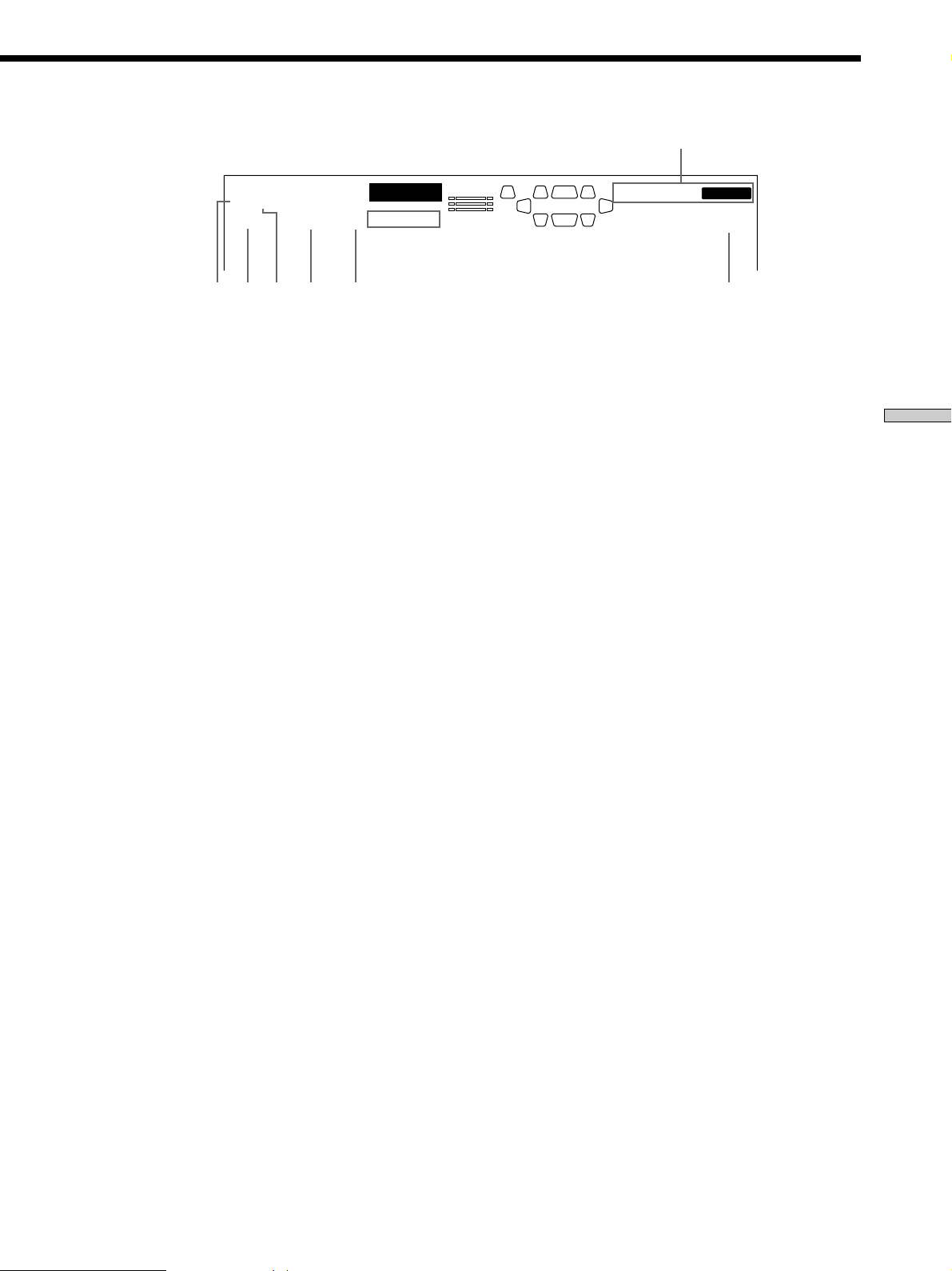
35
Enjoying Surround Sound
q; Tuner indicators
These indicators light up when using the receiver to
tune in radio stations, etc. See pages 44 – 47 for tuner
operations.
qa SLEEP
Lights up when sleep timer is activated.
qs EQ
Lights when the equalizer functions.
qd D. RANGE
Lights up when dynamic range compression is active.
See page 37 to adjust the dynamic range compression.
qf DTS
Lights up when DTS signals are input.
Note
When playing a DTS format disc, be sure that you
have made digital connections and that INPUT MODE
is NOT set to ANALOG (see qa on page 27).
qg SP. OFF
Lights up when headphone is inserted or the
SPEAKERS button is set to OFF.
qh ;
Lights up when Dolby Digital signals are input.
PRO LOGIC
EQD.RANGE
OPTCOAXMULTI CH IN
SP.OFF
SLEEP
STEREO MONO
SL
LC
SSB
SR
R
L.F.E.
DTS MPEG
a
MEMORY
DIGITAL
a
SW
qfqh
qs qaqd
qg
q;
36
Enjoying Surround Sound
Customizing Sound Fields
By adjusting the surround parameters and the equalizer
of the front, center, surround and surround back speakers,
you can customize the sound fields to suit your particular
listening situation.
Once you customize a sound field, the changes are stored
in memory indefinitely. You can change a customized
sound field any time by making new adjustments to the
parameters.
See the table on pages 39 – 43 for the parameters available
in each sound field.
To get the most from multi channel
surround sound
Position your speakers and do the procedures described
in “Multi Channel Surround Setup” starting on page 19
before you customize a sound field.
Adjusting the surround parameters
The SURR menu contains parameters that let you
customize various aspects of the current sound field. The
settings available in this menu are stored individually for
each sound field.
1 Start playing a program source encoded with multi
channel surround sound.
2 Press SURR.
The button lights up and the first parameter is
displayed.
3 Press the cursor buttons ( or ) to select the
parameter you want to adjust.
4 Turn the jog dial to select the setting you want.
The setting is stored automatically.
Pro Logic (PRO LOGIC)
Initial setting : AUTO
Lets you specify the Pro Logic decoding setting.
• When set to “AUTO”, the receiver performs PRO
LOGIC decoding if Dolby surround encoded flag is ON
or if Pro Logic decoding produces a better sound field.
• When set to “ON”, the receiver performs PRO LOGIC
decoding on surround signals, regardless of the Dolby
surround encoded flag.
• When set to “OFF”, the receiver does not perform PRO
LOGIC decoding.
Note
Pro Logic decoding does not function for MPEG format signals.
Effect level (EFFECT)
Initial setting : (depends on sound mode)
Lets you adjust the “presence” of the current surround
effect.
Wall type (WALL S_I_H)
Initial setting : Midpoint
Lets you control the level of the high frequencies to alter
the sonic character of your listening environment by
simulating a softer (S) or harder (H) wall. The midpoint
designates a neutral wall (made of wood).
Reverberation (REVERB S_I_L)
Initial setting : Midpoint
Lets you control the spacing of the early reflections to
simulate a sonically longer (L) or shorter (S) room. The
midpoint designates a standard room with no adjustment.
Front reverberation (FRONT REVERB)
Initial setting : STD
This parameter can be used when “DIGITAL CONCERT
HALL A, B” is selected. This parameter lets you adjust the
amount of reverberations to add to the front signals
according to the original reverberations in the source.
• To increase front reverberations, select “WET”.
• To decrease front reverberations, select “DRY”.
Screen depth (SCREEN DEPTH)
Initial setting : MID
In a movie theater, sound seems to come from inside the
image reflected on the movie screen. This parameter
allows you to create the same sensation in your listening
room by shifting the sound of the front speakers “into”
the screen. “DEEP” provides the greatest amount of
screen depth.
Virtual speaker (VIR. SPEAKERS)
Initial setting : ON
Allows you turn the virtual speakers created by the
CINEMA STUDIO EX A, B, C and SEMI CINEMA
STUDIO EX A, B, C sound fields off or on.

37
Enjoying Surround Sound
Adjusting the level parameters
The LEVEL menu contains parameters that let you adjust
the balance and speaker volumes of each speaker. The
settings available in this menu are applied to all sound
fields.
1 Start playing a program source encoded with multi
channel surround sound.
2 Press LEVEL.
The button lights up and the first parameter is
displayed.
3 Press the cursor buttons ( or ) to select the
parameter you want to adjust.
4 Turn the jog dial to select the setting you want.
The setting is stored automatically.
Front balance (FRONT L_I_R)
Initial setting : Center
Lets you adjust the balance between the front left and
right speakers.
Surround balance (SURROUND L_I_R)
Initial setting : Center
Lets you adjust the balance between the surround left and
right speakers.
Center level (CENTER LEVEL XXX dB)
Initial setting : 0 dB
Lets you adjust the level of the center speaker.
Surround level (SURROUND LEVEL XXX dB)
Initial setting : 0 dB
Lets you adjust level of the surround (left and right)
speakers.
Surround back level (SURR BACK LEVEL XXX dB)
Initial setting : 0 dB
Lets you adjust the level of the surround back speaker.
Sub woofer level (S. WOOFER LEVEL XXX dB)
Initial setting : 0 dB
Lets you adjust the level of the sub woofer.
Low Frequency Effect (LFE MIX XXX dB)
Initial setting : 0 dB
Lets you attenuate the level of the LFE (Low Frequency
Effect) channel output from the sub woofer without
affecting the level of the bass frequencies sent to the sub
woofer from the front, center or surround channels via the
Dolby Digital or DTS bass redirection circuitry.
• For LFE mix level, “0 dB” outputs the full LFE signal at
the mix level determined by the recording engineer.
• To mute the sound of the LFE channel from the sub
woofer, select “OFF”. However, the low frequency
sounds of the front, center, or surround speakers are
output from the sub woofer according to the settings
made for each speaker in the speaker setup (pages 19 –
23).
Dynamic range compressor (D. RANGE COMP.)
Initial setting : OFF
Lets you compress the dynamic range of the sound track.
This may be useful when you want to watch movies at
low volumes late at night. We recommend using the
“MAX” setting.
• To reproduce the sound track with no compression,
select “OFF”.
• To reproduce the sound track with the dynamic range
intended by the recording engineer, select “STD”.
• To compress the dynamic range in small steps to
achieve the sound you desire, select “0.1 –“0.9”.
• To reproduce a dramatic compression of the dynamic
range, select “MAX”.
Note
Dynamic range compression is possible with Dolby Digital
sources only.
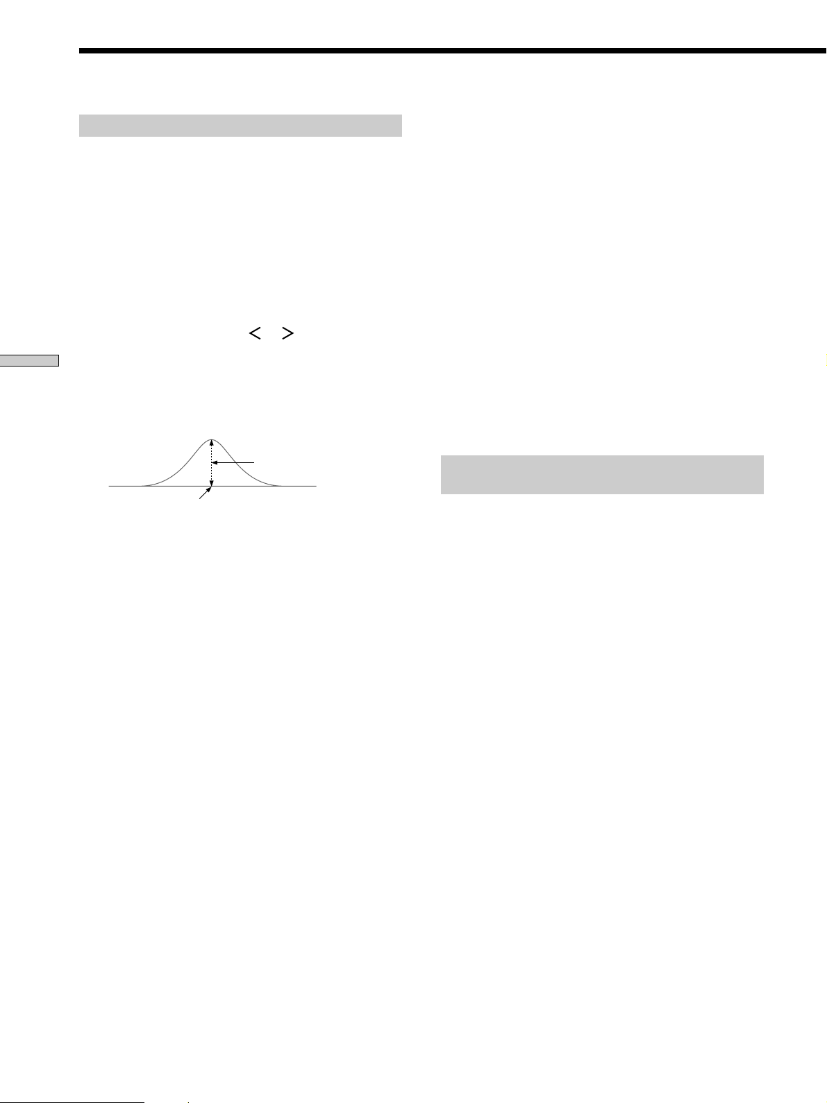
38
Enjoying Surround Sound
Customizing Sound Fields
Adjusting the equalizer
The EQ menu lets you adjust the equalization of the front,
center, surround, and surround back speakers. The
settings are stored individually for each sound field.
1 Start playing a program source encoded with multi
channel surround sound.
2 Press EQ.
The button lights up and the first parameter is
displayed.
3 Press the cursor buttons ( or ) to select the
parameter (gain (dB), bandwidth, frequency (Hz))
you want to adjust.
4 Turn the jog dial to select the setting you want.
The setting is entered automatically.
To turn on/ off the equalizer
Press EQUALIZER. The EQ indicator in the display lights
up when the equalizer is turned on. When you adjust the
equalizer using the EQ parameters, the settings are stored
separately for each sound field and can be reproduced
whenever you turn on the equalizer.
Front speaker bass adjustment (Level/ Frequency)
Lets you adjust the gain and frequency of bass.
Front speaker midrange adjustment (Level/
Frequency)
Lets you adjust the gain and frequency of midrange.
Front speaker treble adjustment (Level/
Frequency)
Lets you adjust the gain and frequency of treble.
Center speaker bass adjustment (Level/
Frequency)
Lets you adjust the gain and frequency of bass.
Center speaker midrange adjustment (Level/
Frequency)
Lets you adjust the gain and frequency of midrange.
Level (dB)
Frequency (Hz)
Center speaker treble adjustment (Level/
Frequency)
Lets you adjust the gain and frequency of treble.
Surround speaker bass adjustment (Level/
Frequency)
Lets you adjust the gain and frequency of bass.
Surround speaker treble adjustment (Level/
Frequency)
Lets you adjust the gain and frequency of treble.
Surround back speaker bass adjustment (Level/
Frequency)
Lets you adjust the gain and frequency of bass.
Surround back speaker treble adjustment (Level/
Frequency)
Lets you adjust the gain and frequency of treble.
Resetting customized sound fields to the
factory settings
1 If the power is on, press ?/1 to turn off the power.
2 Hold down SOUND FIELD MODE and press ?/1.
“S.F Initialize” appears in the display and all sound
fields are reset at once.

39
Enjoying Surround Sound
Adjustable parameters for each sound field
The adjusted SURR and EQ parameters are stored in each sound field. The adjusted LEVEL parameters are applied to all
the sound fields.
< SURR >
PRO EFFECT WALL REVERB FRONT SCREEN VIRTUAL
LOGIC LEVEL TYPE TIME REVERB DEPTH SPEAKERS
2CH
A.F.D. AUTO
NORMAL SURROUND z
CINEMA STUDIO EX A zz z z
CINEMA STUDIO EX B zz z z
CINEMA STUDIO EX C zz z z
SEMI CINEMA STUDIO EX A zz z z
SEMI CINEMA STUDIO EX B zz z z
SEMI CINEMA STUDIO EX C zz z z
NIGHT THEATER zzzz
MONO MOVIE zzzz
STEREO MOVIE zzzz
V. MULTI DIMENSION z
VIRTUAL MULTI REAR z
V. SEMI M. DIMENSION z
VIRTUAL ENHANCED A z
VIRTUAL ENHANCED B z
DIGITAL CONCERT HALL A zz z
DIGITAL CONCERT HALL B zz z
CHURCH zzzz
OPERA HOUSE zzzz
JAZZ CLUB zzzz
DISCO/CLUB zzzz
LIVE HOUSE zzzz
ARENA zzzz
STADIUM zzzz
GAME zzzz
HEADPHONE (2CH)
HEADPHONE (DIRECT)
HEADPHONE THEATER zz
MULTI CH IN
2CH ANALOG DIRECT
PCM96K

40
Enjoying Surround Sound
Customizing Sound Fields
1)
These parameters may not operate depending on the source or adjustments. For details, see each item in “Adjusting the level
parameters” (page 37).
2)
When these sound fields are selected, there is no sound output from the SUB WOOFER terminal if your front speaker size is set to
“LARGE”. However, sound will be output from the sub woofer if the digital input signal contains L.F.E. signals.
Adjustable parameters for each sound field (continued)
< LEVEL >
FRONT SURR CENTER SURR SURR BACK SUB WOOFER LFE D. RANGE
BAL BAL LEVEL LEVEL LEVEL LEVEL MIX
1)
COMP.
1)
2CH z zz
A.F.D. zzzzz z z z
NORMAL SURROUND zzzzz z z z
CINEMA STUDIO EX A zzzzz z z z
CINEMA STUDIO EX B zzzzz z z z
CINEMA STUDIO EX C zzzzz z z z
SEMI CINEMA STUDIO EX A zz zzz
SEMI CINEMA STUDIO EX B zz zzz
SEMI CINEMA STUDIO EX C zz zzz
NIGHT THEATER zzzzz z z z
MONO MOVIE zzzzz z z z
STEREO MOVIE zzzzz z z z
V. MULTI DIMENSION zzzzz z z z
VIRTUAL MULTI REAR zzzzz z z z
V. SEMI M. DIMENSION zz zzz
VIRTUAL ENHANCED A zz zzz
VIRTUAL ENHANCED B zz zzz
DIGITAL CONCERT HALL A zzzzz z
2)
zz
DIGITAL CONCERT HALL B zzzzz z
2)
zz
CHURCH zzzzz z
2)
zz
OPERA HOUSE zzzzz z
2)
zz
JAZZ CLUB zzzzz z
2)
zz
DISCO/CLUB zzzzz z z z
LIVE HOUSE zzzzz z
2)
zz
ARENA zzzzz z
2)
zz
STADIUM zzzzz z
2)
zz
GAME zzzzz z z z
HEADPHONE (2CH) z z
HEADPHONE (DIRECT) z
HEADPHONE THEATER z z
MULTI CH IN zz z z z
2CH ANALOG DIRECT z
PCM96K z

41
Enjoying Surround Sound
Adjustable parameters for each sound field (continued)
<EQ >
< FRONT >
BASS BASS MID MID TREBLE TREBLE
GAIN FREQ GAIN FREQ GAIN FREQ
2CH zz zz z z
A.F.D. zz zz z z
NORMAL SURROUND zz zz z z
CINEMA STUDIO EX A zz zz z z
CINEMA STUDIO EX B zz zz z z
CINEMA STUDIO EX C zz zz z z
SEMI CINEMA STUDIO EX A zz zz z z
SEMI CINEMA STUDIO EX B zz zz z z
SEMI CINEMA STUDIO EX C zz zz z z
NIGHT THEATER zz zz z z
MONO MOVIE zz zz z z
STEREO MOVIE zz zz z z
V. MULTI DIMENSION zz zz z z
VIRTUAL MULTI REAR zz zz z z
V. SEMI M. DIMENSION zz zz z z
VIRTUAL ENHANCED A zz zz z z
VIRTUAL ENHANCED B zz zz z z
DIGITAL CONCERT HALL A zz zz z z
DIGITAL CONCERT HALL B zz zz z z
CHURCH zz zz z z
OPERA HOUSE zz zz z z
JAZZ CLUB zz zz z z
DISCO/CLUB zz zz z z
LIVE HOUSE zz zz z z
ARENA zz zz z z
STADIUM zz zz z z
GAME zz zz z z
HEADPHONE (2CH) zz zz z z
HEADPHONE (DIRECT)
HEADPHONE THEATER zz zz z z
MULTI CH IN
2CH ANALOG DIRECT
PCM96K

42
Enjoying Surround Sound
Adjustable parameters for each sound field (continued)
<EQ >
< CENTER >
BASS BASS MID MID TREBLE TREBLE
GAIN FREQ GAIN FREQ GAIN FREQ
2CH
A.F.D. zz zz z z
NORMAL SURROUND zz zz z z
CINEMA STUDIO EX A zz zz z z
CINEMA STUDIO EX B zz zz z z
CINEMA STUDIO EX C zz zz z z
SEMI CINEMA STUDIO EX A zz zz z z
SEMI CINEMA STUDIO EX B zz zz z z
SEMI CINEMA STUDIO EX C zz zz z z
NIGHT THEATER zz zz z z
MONO MOVIE zz zz z z
STEREO MOVIE zz zz z z
V. MULTI DIMENSION zz zz z z
VIRTUAL MULTI REAR zz zz z z
V. SEMI M. DIMENSION zz zz z z
VIRTUAL ENHANCED A zz zz z z
VIRTUAL ENHANCED B zz zz z z
DIGITAL CONCERT HALL A zz zz z z
DIGITAL CONCERT HALL B zz zz z z
CHURCH zz zz z z
OPERA HOUSE zz zz z z
JAZZ CLUB zz zz z z
DISCO/CLUB zz zz z z
LIVE HOUSE zz zz z z
ARENA zz zz z z
STADIUM zz zz z z
GAME zz zz z z
HEADPHONE (2CH)
HEADPHONE (DIRECT)
HEADPHONE THEATER
MULTI CH IN
2CH ANALOG DIRECT
PCM96K
Customizing Sound Fields

43
Enjoying Surround Sound
Adjustable parameters for each sound field (continued)
<EQ >
< SURROUND/SURROUND BACK >
BASS BASS TREBLE TREBLE
GAIN FREQ GAIN FREQ
2CH
A.F.D. zz z z
NORMAL SURROUND zz z z
CINEMA STUDIO EX A zz z z
CINEMA STUDIO EX B zz z z
CINEMA STUDIO EX C zz z z
SEMI CINEMA STUDIO EX A
SEMI CINEMA STUDIO EX B
SEMI CINEMA STUDIO EX C
NIGHT THEATER zz z z
MONO MOVIE zz z z
STEREO MOVIE zz z z
V. MULTI DIMENSION zz z z
VIRTUAL MULTI REAR zz z z
V. SEMI M. DIMENSION
VIRTUAL ENHANCED A
VIRTUAL ENHANCED B
DIGITAL CONCERT HALL A zz z z
DIGITAL CONCERT HALL B zz z z
CHURCH zz z z
OPERA HOUSE zz z z
JAZZ CLUB zz z z
DISCO/CLUB zz z z
LIVE HOUSE zz z z
ARENA zz z z
STADIUM zz z z
GAME zz z z
HEADPHONE (2CH)
HEADPHONE (DIRECT)
HEADPHONE THEATER
MULTI CH IN
2CH ANALOG DIRECT
PCM96K

44
You can tune in stations on this receiver in the following
ways:
Direct Tuning
You can enter a frequency of the station you want directly
by using the numeric buttons on the remote (see page 46).
Automatic Tuning
If you don’t know the frequency of the station you want,
you can let the receiver scan all available stations in your
area (see page 46).
Preset Tuning
After you have tuned in stations using Direct Tuning or
Automatic Tuning, you can preset them to the receiver
(see page 47). Then you can tune in any of the stations
directly by entering its 2-character code (see page 47). Up
to 30 FM or AM stations can be preset. The receiver will
also scan all the stations that you have preset (see page
47).
Before you begin, make sure you have:
• Connected an FM and AM antenna to the receiver (see
page 5).
Receiving
Broadcasts
This chapter describes how to receive
FM or AM broadcasts and how to
preset selected stations.
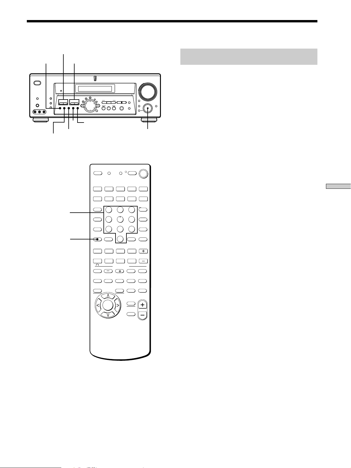
45
Receiving Broadcasts
Brief descriptions of buttons used to
receive broadcasts
PRESET TUNING +/–: Press to scan all preset radio
stations.
TUNING +/–: Press to scan all available radio stations.
FM MODE: If “STEREO” flashes in the display and the
FM stereo reception is poor, press this button to improve
the sound. You will not be able to enjoy stereo effect but
the sound will be less distorted.
Note
If “STEREO” does not appear at all even when the FM broadcast
is received normally, press this button to turn on the “STEREO”
indication.
FM: Press to select the FM band.
AM: Press to select the AM band.
MEMORY: Uses for memorizing preset stations.
SHIFT: Press to select a memory page (A, B, or C) for
presetting radio stations or tuning to preset stations.
FUNCTION control: Rotate to select the tuner or other
souce.
On the remote:
D. TUNING: Press this button to enter a frequency directly
using the numeric buttons.
Numeric buttons: Press to enter a numeric value when
inputting the frequency directly, presetting radio stations,
or tuning to preset stations.
? / 1
DISPLAY
DIMMER
ON SCREEN
MEMORY SHIFT FM MODE FM AM
PRESET
TUNING
TUNING
–
+
–
+
MULTI CHANNEL DECODING
A.F.D.
SOUND FIELD
MULTI /2CH A. DIRECT
DIGITAL CONCERT HALL
EQUALIZER
MUTING
INPUT MODE
MODE
2ND ROOM
FUNCTION
6.1 CH DECODING
CINEMA STUDIO EX
AA
MODE 2CH
PHONES
VIDEO 3 INPUT
VIDEO L AUDIO R
SPEAKERS
EQ
SURR
LEVEL
SET UP
NAME
ENTER
BBC
MASTER VOLUME
+
–
FM
AM
PRESET TUNING +/–
TUNING +/–
FM MODE FUNCTION
MEMORY
SHIFT
>10
1
4
7
2
5
8
3
6
9
0
MONITOR
2ND ROOM
VIDEO 1 VIDEO 2 VIDEO 3 DVD/LD TV/SAT
AUX
TV/VIDEO
INPUT MODE
CLEAR
– SUB CH +
– VOL +
POSITION SWAP
SEARCH
MODE
AUDIO
SPLIT
ENTER
ANT
TV/VTR
D. SKIP/
CH/PRESET
MD/TAPE CD/SACD TUNER PHONO
SHIFT
DISC
JUMP
A.F.D.
AV
DISPLAY
TEST
TONE
NIGHT
MODE
ON
SCREEN
MAIN
MENU
EXIT/
RETURN
AV
MENU
TITLE
GUIDE
ENTER/
EXEC
MULTI/2CH
A. DIRECT
EQ/TONE
MUTING
MUTING
MODE
2CH
PRESET
P IN P
– /– –
SOUND FIELD
D.TUNING
AV1 AV2 3RD
(SOURCE)
WIDE
/11 /10 /12
SLEEP
AV
? / 1
? / 1
SYSTEM
STANDBY
USE MODE
MASTER
VOL
.Mm
nN
X
>
x
D.TUNING
Numeric buttons
STR-DE875 only
46
Receiving Broadcasts
bb
35
1
b
0
Direct Tuning
For details on the buttons used in this section, see “Brief
descriptions of buttons used to receive broadcasts” on
page 45.
1 Rotate FUNCTION to select the tuner.
The last received station is tuned in.
2 Press FM or AM to select the FM or AM band.
3 Press D.TUNING on the remote.
4 Press the numeric buttons on the remote to enter
the frequency.
Example 1: FM 102.50 MHz
Example 2: AM 1350 kHz
(You don’t have to enter the last “0” when the tuning interval
is set to 10 kHz)
If you cannot tune in a station and the
entered numbers flash
Make sure you’ve entered the right frequency. If not,
repeat Steps 3 and 4.
If the entered numbers still flash, the frequency is not
used in your area.
5 If you’ve tuned in an AM station, adjust the
direction of the AM loop antenna for optimum
reception.
6 Repeat Steps 2 to 5 to receive other stations.
z
If you try to enter a frequency not covered by the tuning
interval
The entered value is automatically rounded up or down.
Tuning intervals for direct tuning are:
FM: 50 kHz
AM: 10 kHz (to change to 9 kHz, see page 58.)
Automatic Tuning
For details on the buttons used in this section, see “Brief
descriptions of buttons used to receive broadcasts” on
page 45.
1 Rotate FUNCTION to select the tuner.
The last received station is tuned in.
2 Press FM or AM to select the FM or AM band.
3 Press TUNING + or TUNING –.
Press the + button to scan from low to high; press the –
button to scan from high to low.
When the receiver reaches either end of the
band
Scanning is repeated in the same direction.
The receiver stops scanning whenever a station is
received.
4 To continue scanning, press TUNING + or TUNING –
again.
bbbb
025
0
1

47
Receiving Broadcasts
nA1˜A2˜...˜A0˜B1˜B2˜...˜B0N
nC0˜...C2˜C1N
Preset Tuning
For details on the buttons used in this section, see “Brief
descriptions of buttons used to receive broadcasts” on
page 45.
Before tuning to preset stations, be sure to preset them by
performing steps on “Presetting radio stations” below.
Presetting radio stations
1 Rotate FUNCTION to select the tuner.
The last received station is tuned in.
2 Tune in the station that you want to preset using
Direct Tuning or Automatic Tuning (page 46).
3 Press MEMORY.
“MEMORY” appears in the display for a few seconds.
Do Steps 4 to 6 before “MEMORY” goes out.
4 Press SHIFT to select a memory page (A, B or C).
Each time you press SHIFT, the letter “A”, “B” or “C”
appears in the display.
5 Select a preset number by pressing PRESET TUNING
+ or PRESET TUNING –.
If “MEMORY” goes out before you press the preset
number, start again from Step 3.
6 Press MEMORY again to store the station.
If “MEMORY” goes out before you can store the
station, start again from Step 3.
7 Repeat Steps 2 to 6 to preset another station.
To change a preset number to another station
Do Steps 1 to 6 to preset the new station to the number.
Tuning to preset stations
You can tune the preset stations either of the following
two ways.
Scanning the preset stations
1 Rotate FUNCTION to select the tuner.
The last received stations is tuned in.
2 Press PRESET TUNING + or PRESET TUNING –
repeatedly to select the preset station you want.
Each time you press the button, the receiver tunes in
one preset station at a time , in the corresponding
order and direction as follows:
Using the preset codes
1 Rotate FUNCTION to select the tuner.
The last received stations is turned in.
2 Press SHIFT to select a memory page (A, B or C),
then press the preset number of the station you
want using the numeric buttons on the supplied
remote.
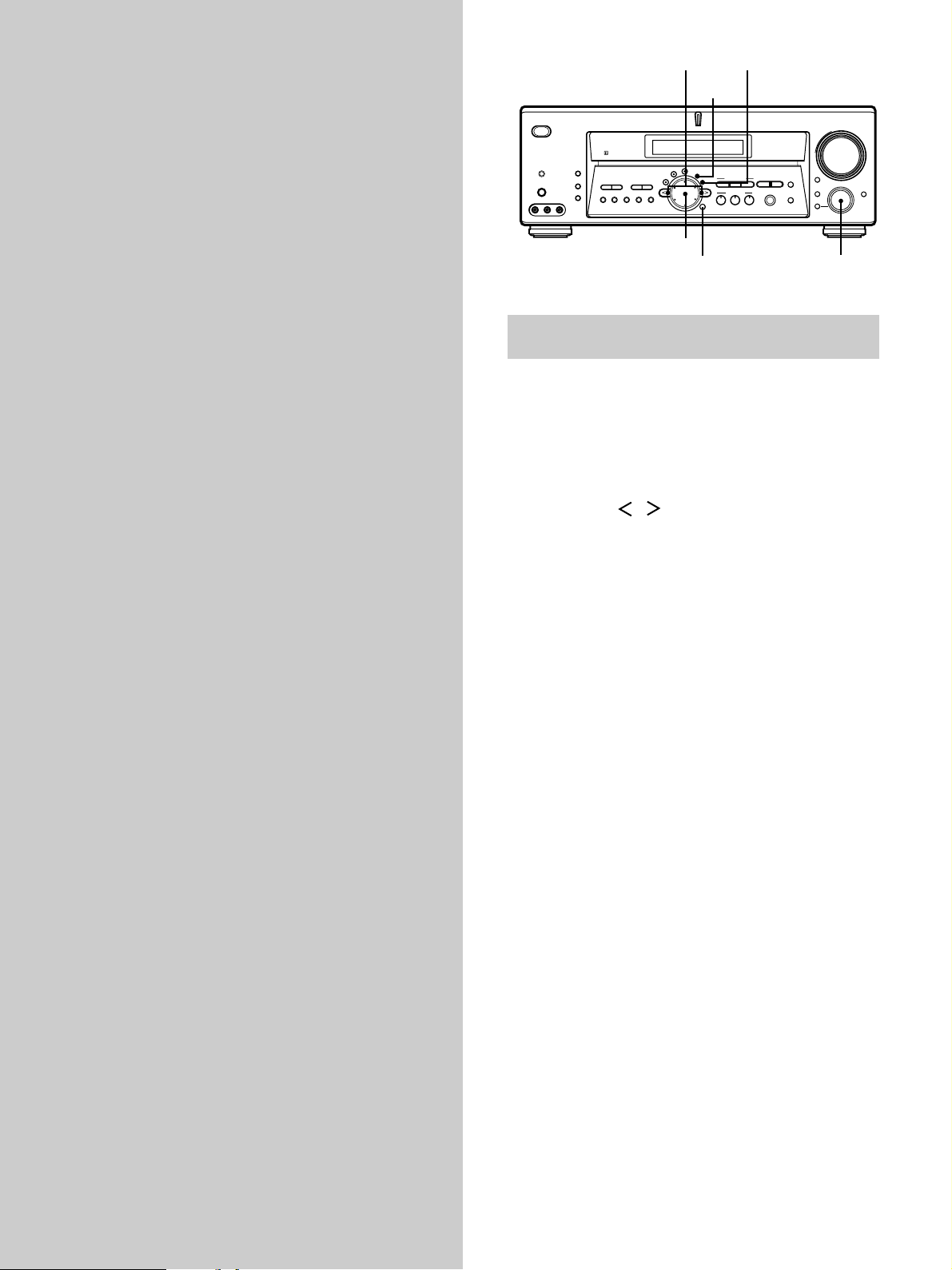
48
? / 1
DISPLAY
DIMMER
ON SCREEN
MEMORY SHIFT FM MODE FM AM
PRESET
TUNING
TUNING
–
+
–
+
MULTI CHANNEL DECODING
A.F.D.
SOUND FIELD
MULTI /2CH A. DIRECT
DIGITAL CONCERT HALL
EQUALIZER
MUTING
INPUT MODE
MODE
2ND ROOM
FUNCTION
6.1 CH DECODING
CINEMA STUDIO EX
AA
MODE 2CH
PHONES
VIDEO 3 INPUT
VIDEO L AUDIO R
SPEAKERS
EQ
SURR
LEVEL
SET UP
NAME
ENTER
BBC
MASTER VOLUME
+
–
FUNCTION
NAME
SET UP
ENTER
Cursor buttons
Jog dial
Other
Operations
Brief descriptions of buttons that appear
in this chapter
NAME button: Press to name preset stations or program
sources.
Jog dial: Use to select characters when naming preset
stations or program sources.
Cursor buttons ( / ): Use to move the cursor when
naming preset stations or program sources.
FUNCTION control: Rotate to select the tuner or other
source.
SET UP button: Press to enter the set up mode.
ENTER button: Press to enter the completed name of the
preset station or program source.
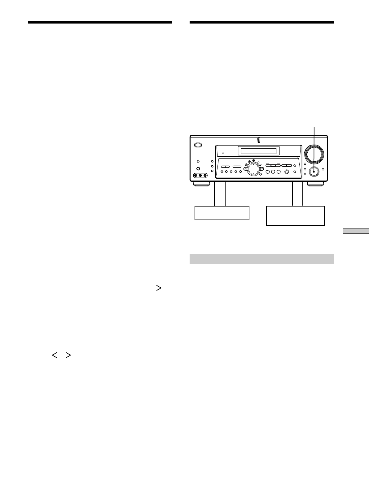
49
Other Operations
Playback component
(program source)
c
ç
ç
c
Recording component
(tape deck, MD deck,
VCR)
? / 1
DISPLAY
DIMMER
ON SCREEN
MEMORY SHIFT FM MODE FM AM
PRESET
TUNING
TUNING
–
+
–
+
MULTI CHANNEL DECODING
A.F.D.
SOUND FIELD
MULTI /2CH A. DIRECT
DIGITAL CONCERT HALL
EQUALIZER
MUTING
INPUT MODE
MODE
2ND ROOM
FUNCTION
6.1 CH DECODING
CINEMA STUDIO EX
AA
MODE 2CH
PHONES
VIDEO 3 INPUT
VIDEO L AUDIO R
SPEAKERS
EQ
SURR
LEVEL
SET UP
NAME
ENTER
BBC
MASTER VOLUME
+
–
FUNCTION
Naming Preset Stations and
Program Sources
You can enter a name (index name) of up to 8 characters
for preset stations and program sources. These names (for
example, “VHS”) appear in the receiver’s display when a
station or program source is selected.
Note that no more than one name can be entered for each
preset station or program source.
This function is useful for distinguishing components of
the same kind. For example, two VCRs can be specified as
“VHS” and “8MM”, respectively. It is also handy for
identifying components connected to jacks meant for
another type of component, for example, a second CD
player connected to the MD/TAPE jacks.
1 To name a preset station
Rotate FUNCTION to select the tuner.
The last station you received is tuned in.
To name a program source
Select the program source (component) to be
named, then go to Step 3.
2 Tune in the preset station you want to create an
index name for.
If you are not familiar with how to tune in preset
stations, see “Tuning to preset stations” on page 47.
3 Press NAME.
4 Create an index name by using the jog dial and
cursor buttons:
Turn the jog dial to select a character, then press
to
move the cursor to the next position.
To insert a space
Turn the jog dial until a blank space appears in the
display (you can find the space character between “??”
and “A”).
If you’ve made a mistake
Press
or repeatedly until the character to be
changed flashes, then turn the jog dial to select the
right character.
5 Press ENTER.
To assign index names to other stations
Repeat Steps 2 to 5.
Recording
Your receiver makes it easy to record to and from the
components connected to it. You don’t have to connect the
playback and recording components directly to each
other: once you select a program source on the receiver,
you can record and edit as you normally would using the
controls on each component.
Before you begin, make sure you’ve connected all
components properly.
ç: Audio signal flow
c: Video signal flow
Recording on an audio tape or MiniDisc
You can record on a cassette tape or MiniDisc using the
receiver. Refer to the instruction manual of your cassette
deck or MD deck if you need help.
1 Select the component to be recorded.
2 Prepare the component for playing.
For example, insert a CD into the CD player.
3 Insert a blank tape or MD into the recording deck
and adjust the recording level, if necessary.
4 Start recording on the recording deck, then start
playback on the playback component.
50
Other Operations
You can set the receiver to turn off automatically at a
specified time.
Press SLEEP on the remote while the power is on.
Each time you press SLEEP, the time changes as shown
below.
n 2:00:00 n 1:30:00n 1:00:00 n 0:30:00 n OFF
The display dims after you have specified the time. While
using Sleep Timer, “SLEEP” lights up in the display.
Tips
• You can freely specify the time. After pressing SLEEP, specify
the time you want using the jog dial and cursor buttons
( or ) on the receiver. The sleep time changes in 1 second
intervals. You can specify up to 5 hours.
• To check the remaining time before the receiver turns off, press
SLEEP. The remaining time appears in the display.
Recording on a video tape
You can record from a VCR, a TV, or an LD player using
the receiver. You can also add audio from a variety of
audio sources when editing a video tape. See your VCR or
LD player’s instruction manual if you need help.
1 Select the program source to be recorded.
2 Prepare the component for playing.
For example, insert the laser disc you want to record
into the LD player.
3 Insert a blank video tape into the VCR (VIDEO 1 or
VIDEO 2) for recording.
4 Start recording on the recording VCR, then start
playing the video tape or laser disc you want to
record.
z
You can record the sound from any audio source onto a
video tape while recording from a video tape or laser disc
Locate the point where you want to start recording from another
audio source, select the program source, then start playback. The
audio from that source will be recorded onto the audio track of
the video tape instead of the audio from the original medium.
To resume audio recording from the original medium, select the
video source again.
Notes
• Please be sure to make both digital and analog connections to
the TV/SAT and DVD/LD inputs. Analog recording is not
possible if you only make digital connections.
• Some sources contain copy guards to prevent recording. In this
case, you may not be able to record from the sources.
• You cannot record a digital audio signal using a component
connected to the analog TAPE OUT (STR-DE975 only) or MD/
DAT OUT (STR-DE975 only) or MD/TAPE OUT (STR-DE875
only) jacks. To record a digital audio signal, connect a digital
component to the DIGITAL MD/DAT OUT (STR-DE975 only)
or DIGITAL MD/TAPE OUT (STR-DE875 only) jacks.
• Sound adjustments do not affect the signal output from the
TAPE OUT (STR-DE975 only) or MD/DAT OUT (STR-DE975
only) or MD/TAPE OUT (STR-DE875 only) jacks.
• When MULTI/2CH A. DIRECT is set to MULTI DIRECT, audio
signals are not output from REC OUT jacks.
• No signals output from DIGITAL OUT jacks (MD/DAT
OPTICAL OUT (STR-DE975 only) or MD/TAPE OPTICAL
OUT (STR-DE875 only) when you set MULTI/2CH A. DIRECT
to 2CH A. DIRECT.
Using the Sleep Timer
Recording
51
Other Operations
Sound Field Link
When set to “ON”, the sound field that was last applied to
a program source is automatically applied whenever it is
selected. For example, if you listen to CD with STADIUM
as the sound field, change to a different program source,
then return to CD, STADIUM will be applied again. If you
do not want to use this function, set to “OFF”. The default
setting is “ON”.
1 Press SET UP.
2 Press the cursor buttons ( or ) to select “S.
FIELD LINK”.
3 Turn the jog dial to select “ON” or “OFF”.
Adjusting the CONTROL A1 auto power
on
Lets you turn on the receiver automatically when the
component connected via CONTROL A1 cords (see page
12) is turned on and the playback is started.
When set to “OFF”, you can save the power consumption
of the receiver during standby mode. The default setting
is “ON”.
1 Press SET UP.
2 Press the cursor buttons ( or ) to select “AI
AUTO POWER”.
3 Turn the jog dial to select “ON” or “OFF”.
Adjusting the CONTROL A1 auto
function
Lets you switch the function of this receiver to the Sony
components connected via CONTROL A1 cords (see page
12) automatically when the connected component is set to
play mode. The default setting is “ON”.
1 Press SET UP.
2 Press the cursor buttons ( or ) to select “AUTO
FUNCTION”.
3 Turn the jog dial to select “ON” or “OFF”.
The SET UP button allows you to make the following
adjustments other than specifying the speaker parameters.
6.1 CH DECODING
This parameter lets you enjoy the appropriate surround
sound from the surround channels. The default setting is
“AUTO”.
1 Press SET UP.
2 Press the cursor buttons ( or ) to select
“6.1 CH DECODING”.
3 Turn the jog dial to select “AUTO”, “ON” or “OFF”.
Notes
• You can set this parameter using 6.1 CH DECODING on the
front panel.
• When set to “AUTO”, the receiver performs 6.1 channel matrix
decoding only if 6.1 channel signals decode flag is ON.
• When set to “ON”, the receiver performs 6.1 channel matrix
decoding only if the surround signals are 2 channel, regardless
of the 6.1 channel decode flag.
• When set to “OFF”, the receiver does not perform 6.1 channel
matrix decoding.
• During “A.F.D.” this parameter is always set to “AUTO”, and
you cannot change the setting.
• When the 6.1 channel matrix decoding is performed and the
surround back speaker is set to “NO”, you can enjoy the
surround back signals with Virtual 3D technology, even
without an actual surround back speaker (the box around SB
does not light up). If the surround back speaker is set to “YES”,
the surround back signals are output through the actual
speaker (
SB
lights up). Please note that you can set the
surround back speaker only when the center speaker is set to
“NO” (page 20).
Multi channel assignment
Lets you assign a function to MULTI CH. You cannot
assign TUNER or PHONO.
1 Press SET UP.
2 Press the cursor buttons ( or ) to select
“MULTI CH”.
3 Turn the jog dial to select “NONE”, “VIDEO 1”,
“VIDEO 2”, “VIDEO 3” (STR-DE975 only), “DVD/LD”,
“TV/SAT”, “MD/DAT” (STR-DE975 only), “TAPE”
(STR-DE975 only), “MD/TAPE” (STR-DE875 only) and
“CD/SACD”.
Adjustment Using the SET UP Button
52
Other Operations
Selecting the command mode of the
remote
Lets you select the command mode of the remote. Change
the command mode when you use 2 Sony receivers in the
same room. The default setting is “AV1”. For details, see
“Selecting the mode of the remote” on page 65.
1 Press SET UP.
2 Press the cursor buttons ( or ) to select
“COMMAND MODE”.
3 Turn the jog dial to select “AV1” or “AV2”.
Selecting the color of the on-screen
display (STR-DE975 only)
Select the color of the on-screen display. You can
select either “COLOR” or “MONOCHROME”. The
default setting is “COLOR”.
1 Press SET UP.
2 Press the cursor buttons ( or ) to select “OSD”.
3 Turn the jog dial to select “COLOR” or
“MONOCHROME”.
OSD horizontal position (STR-DE975 only)
This parameter lets you adjust the position of the
on-screen display horizontally. The default setting is “4”.
1 Press SET UP.
2 Press the cursor buttons ( or ) to select “OSD
H. POSITION”.
3 Turn the jog dial to select 0-64.
OSD vertical position (STR-DE975 only)
This parameter lets you adjust the position of the
on-screen display vertically. The default setting is “4”.
1 Press SET UP.
2 Press the cursor buttons ( or ) to select “OSD
V. POSITION”.
3 Turn the jog dial to select 0-32.
Adjustment Using the SET UP Button
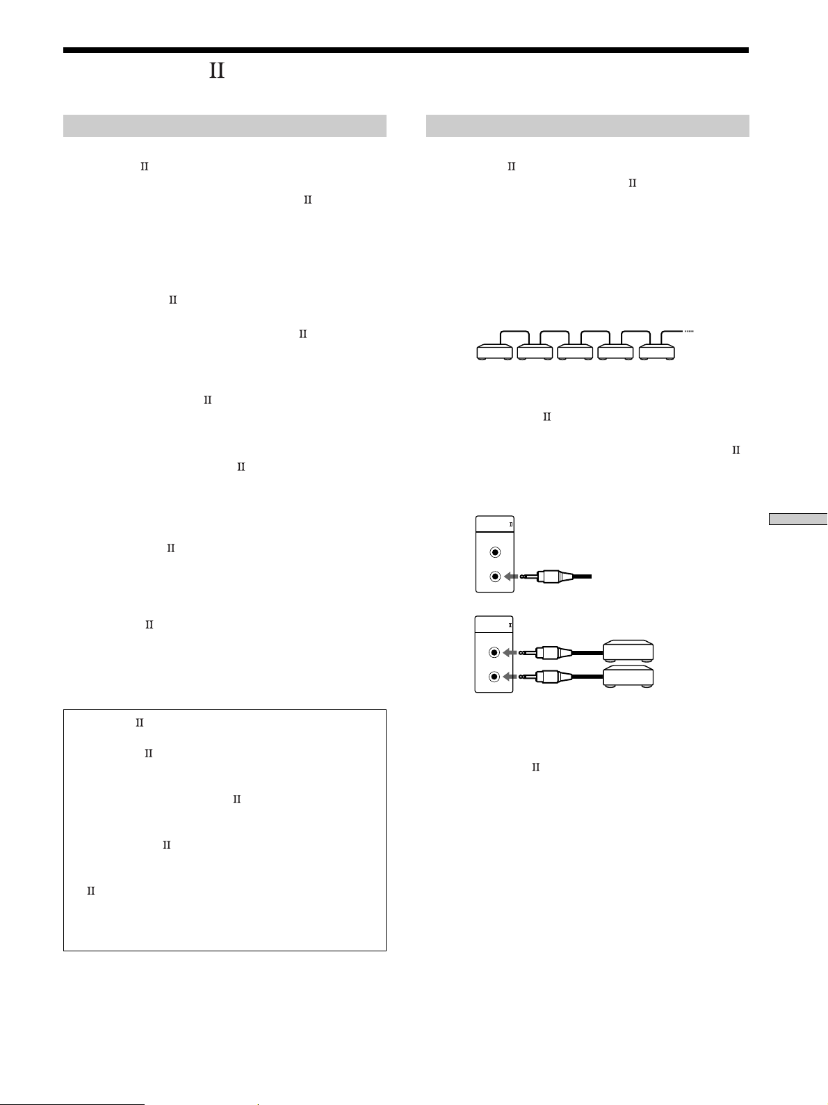
53
Other Operations
Connections
Connect monaural (2P) mini-plug cords in series to the
CONTROL A1
jacks on the back of each component. You
can connect up to ten CONTROL A1
compatible
components in any order. However, you can connect only
one of each type of component (i.e., 1 CD player, 1 MD
deck, 1 tape deck and 1 receiver).
(You may be able to connect more than one CD player or
MD deck, depending on the model. Refer to the operating
instructions supplied with the respective component for
details.)
In the CONTROL A1
control system, the control signals
flow both ways, so there is no distinction of IN and OUT
jacks. If a component has more than one CONTROL A1
jack, you can use either one, or connect different
components to each jack.
On CONTROL A1 jacks and connections
It is possible to make connections between CONTROL A1
and CONTROL A1
jacks. For details regarding
particular connections or setup options, refer to the
Operating Instructions supplied with the component(s).
About the connecting cord
Some CONTROL A1 compatible components are supplied
with a connecting cord as an accessory. In this case, use
the connecting cord for your connection.
When using a commercially available cord, use a
monaural (2P) mini-plug cord less than 2 meters long,
with no resistance (like the Sony RK-G69HG).
CONTROL A1
CONTROL A1
Example
Amplifier
(Receiver)
CD
player
MD
deck
Tape
deck
Other
component
CD player
MD deck
CONTROL A1 and CONTROL A1 compatibility
The CONTROL A1 control system has been updated to the
CONTROL A1 which is the standard system in the SONY
300 disc CD changer and other recent Sony components.
Components with CONTROL A1 jacks are compatible with
components with CONTROL A1 , and can be connected to
each other. Basically, the majority of the functions available
with the CONTROL A1 control system will be available with
the CONTROL A1 control system.
However, when making connections between components
with CONTROL A1 jacks and components with CONTROL
A1 jacks, the number of functions that can be controlled
may be limited depending on the component. For detailed
information, refer to the Operating Instructions supplied with
the component(s).
Getting Started
This section explains the basic functions of the
CONTROL A1
Control System. Certain components
have special functions, like “CD Synchro Dubbing” on
cassette decks, that require CONTROL A1
connections. For detailed information regarding
specific operations, be sure to also refer to the
Operating Instructions supplied with your
component(s).
The CONTROL A1
Control System was designed to
simplify the operation of audio systems composed of
separate Sony components. CONTROL A1
connections
provide a path for the transmission of control signals
which enable automatic operation and control features
usually associated with integrated systems.
Currently, CONTROL A1
connections between a Sony
CD player, amplifier (receiver), MD deck and cassette
deck provide automatic function selection and
synchronized recording.
In the future the CONTROL A1
connection will work as
a multifunction bus allowing you to control various
functions for each component.
Notes
• The CONTROL A1 Control System is designed to maintain
upward compatibility as the Control System is upgraded to
handle new functions. In this case, however, older components
will not be compatible with the new functions.
• Do not operate a 2 way remote control unit when the
CONTROL A1 jacks are connected via a PC interface kit to a
personal computer running “MD Editor” or similar application.
Also, do not operate the connected component in a manner
contrary to the functions of the application, as this may cause
the application to operate incorrectly.
CONTROL A1 Control System

54
Other Operations
Basic Functions
The CONTROL A1 functions will operate as long as the
component you want to operate is turned on, even if all of
the other connected components are not turned on.
Automatic function selection
When you connect a CONTROL A1
compatible Sony
amplifier (or receiver) to other Sony components using
monaural mini-plug cords, the function selector on the
amplifier (or receiver) automatically switches to the
correct input when you press the play button on one of
the connected components.
Notes
• You must connect a CONTROL A1 compatible amplifier
(receiver) using a monaural mini-plug cord in order to take
advantage of the automatic function selection feature.
• This function only works when the components are connected
to the amplifier (or receiver) inputs according to the names on
the function buttons. Certain receivers allow you to switch the
names of the function buttons. In this case, refer to the
Operating Instructions supplied with the receiver.
• When recording, do not play any components other than the
recording source. It will cause the automatic function selection
to operate.
Synchronized recording
This function lets you conduct synchronized recording
between the selected source and recorder components.
1 Set the function selector on the amplifier (or
receiver) to the source component.
2 Set the source component to pause mode (make
sure both the N and X indicators light together).
3 Set the recorder component to the REC-PAUSE
mode.
4 Press PAUSE on the recorder component.
The source component is released from the pause
mode, and recording begins shortly thereafter.
When playback ends from the source component,
recording stops.
Notes
• Do not set more than one component to the pause mode.
• Certain recorder components may be equipped with a special
synchronized recording function that uses the CONTROL A1
Control System, like “CD Synchro Dubbing”. In this case, refer
to the Operating Instructions supplied with the recorder
component.
CONTROL A1 Control System

55
Additional Information
Troubleshooting
If you experience any of the following difficulties while
using the receiver, use this troubleshooting guide to help
you remedy the problem. Also, see “Checking the
connections” on page 24 to verify that the connections are
correct. Should any problem persist, consult your nearest
Sony dealer.
There’s no sound or only a very low-level sound
is heard.
, Check that the speakers and components are
connected securely.
, Make sure that you’ve selected the correct
component on the receiver.
, Press SPEAKERS button if SP. OFF appears on the
display.
, Check that the headphones are not connected.
, Press MUTING if MUTING appears on the display.
, The protective device on the receiver has been
activated because of a short circuit. Turn off the
receiver, eliminate the short-circuit problem and
turn on the power again.
The left and right sounds are unbalanced or
reversed.
, Check that the speakers and components are
connected correctly and securely.
, Adjust front balance parameter in the LEVEL
menu.
Severe hum or noise is heard.
, Check that the speakers and components are
connected securely.
, Check that the connecting cords are away from a
transformer or motor, and at least 10 feet (3 meters)
away from a TV set or fluorescent light.
, Move your TV away from the audio components.
, Make sure you’ve grounded U SIGNAL GND
terminal (only when a turntable is connected).
, The plugs and jacks are dirty. Wipe them with a
cloth slightly moistened with alcohol.
There is intermittent sound from a digital source.
, Check to see if signals with 96 kHz sampling
frequencies are input to the DVD/LD OPTICAL IN
or COAXIAL jacks.
No sound is heard from the center speaker.
, Make sure the sound field function is on (press
SOUND FIELD MODE).
, Select the appropriate center mode (see pages
31 – 33).
, Adjust the speaker volume (see page 23).
, Make sure the center speaker size parameter is set
to either SMALL or LARGE (see page 20).
Additional
Information

56
Additional Information
No sound or only a very low-level sound is heard
from the surround speakers.
, Make sure the sound field function is on (press
SOUND FIELD MODE).
, Select the appropriate center mode (see pages
31 – 33).
, Adjust the speaker volume (see page 23).
, Make sure the surround speaker size parameter is
set to either SMALL or LARGE (see page 20).
No sound is heard from the sub woofer.
, Make sure the sub woofer is set to YES (see page
20).
, Check that 2CH mode has not been selected (see
page 33).
Dolby Digital or DTS multi channel sound is not
reproduced.
, Check that the playing DVD, etc. is recorded in
Dolby Digital or DTS format.
, When connecting the DVD player, etc. to the
digital input jacks of this receiver, check the audio
setting (settings for the audio output) of the
connected component.
Recording cannot be done.
, Check that the components are connected correctly.
, Select the source component by rotating
FUNCTION control.
, When recording from a digital component, make
sure the input mode is set to ANALOG 2CH
FIXED (see page 27) before recording with a
component connected to the analog MD/DAT or
TAPE terminals (STR-DE975) or the analog MD/
TAPE terminals (STR-DE875).
, When recording from a digital component, make
sure the input mode is set to COAXIAL FIXED or
OPTICAL FIXED (see page 27) before recording
with the component connected to the DIGITAL
MD/DAT OUT terminals (STR-DE975) or the
DIGITAL MD/TAPE OUT terminals (STR-DE875).
Radio stations cannot be tuned in.
, Check that the antennas are connected securely.
Adjust the antennas and connect an external
antenna if necessary.
, The signal strength of the stations is too weak
(when tuning in with automatic tuning). Use direct
tuning.
, Make sure you set the tuning interval correctly
(when tuning in AM stations with direct tuning)
(see pages 46 and 58).
, No stations have been preset or the preset stations
have been cleared (when tuning by scanning preset
stations). Preset the stations (see page 47).
, Press DISPLAY so that the frequency appears in
the display.
The surround effect cannot be obtained.
, Make sure the sound field function is on (press
SOUND FIELD MODE).
Nothing appears on the display.
, When the display turns off after the receiver is
turned on, press DIMMER to change the display
mode.
No picture or an unclear picture appears on the
TV screen or monitor.
, Select the appropriate function on the receiver.
, Set your TV to the appropriate input mode.
, Move your TV away from the audio components.
The remote does not function.
, Point the remote at the remote sensor g on the
receiver.
, Remove any obstacles in the path between the
remote and the receiver.
, Replace both batteries in the remote with new
ones, if they are weak.
, Make sure you select the correct function on the
remote.
, If the remote is set to operate the TV only, use the
remote to select a source or component other than
TV before operating the receiver or other
component.
Reference sections for clearing the
receiver’s memory
To clear See
All memorized settings page 18
Customized sound fields page 38
Troubleshooting

57
Additional Information
Specifications
AUDIO POWER
SPECIFICATIONS
POWER OUTPUT AND
TOTAL HARMONIC
DISTORTION:
With 8 ohm loads, both
channels driven, from 20 -
20,000 Hz; rated 110 watts
(STR-DE975) and 100 watts
(STR-DE875) per channel
minimum RMS power,
with no more than 0.09 %
total harmonic distortion
from 250 milliwatts to
rated output (USA model
only).
Amplifier section
Rated Power Output at Stereo mode
(8 ohms 20 Hz - 20 kHz,
THD 0.09%)
STR-DE975:
110 W + 110W
STR-DE875:
100 W + 100W
Reference Power Output
(8 ohms at 1 kHz, THD
0.7%)
STR-DE975:
Front
1)
: 110 W/ch
Center
1)
: 110 W
Surround
1)
: 110 W/ch
STR-DE875:
Front
1)
: 100 W/ch
Center
1)
: 100 W
Surround
1)
: 100 W/ch
1) Depending on the sound field settings and
sources, there may be no sound output.
Frequency response
PHONO: RIAA
equalization curve
±0.5 dB
MULTI CH IN,
CD/SACD,
MD/DAT*,
MD/TAPE**,
DVD/LD, TV/SAT,
VIDEO 1, VIDEO 2
VIDEO 3*:
10 Hz - 50 kHz +0.5/
–2 dB (with sound
field and equalizer
bypassed)
Inputs (Analog)
PHONO:
Sensitivity: 4.0 mV
Impedance:
50 kilohms
S/N
a)
: 86 dB
(A, 4.0 mV
b)
)
MULTI CH IN,
CD/SACD,
DVD/LD,
MD/DAT*,
MD/TAPE**,
TV/SAT, VIDEO 1,
VIDEO 2 VIDEO 3*:
Sensitivity: 250 mV
Impedance:
50 kilohms
S/N
a)
: 96 dB
(A, 250 mV
b)
)
a) Input short.
b) Weighted network, input level.
Inputs (Digital)
DVD/LD (coaxial):
Sensitivity: –
Impedance: 75 ohms
S/N: 100 dB
(A, 20 kHz LPF)
DVD/LD, TV/SAT,
MD/DAT*,
MD/TAPE**
(Optical):
Sensitivity: –
Impedance: –
S/N: 100 dB
(A, 20 kHz LPF)
Outputs MD/DAT*,
MD/TAPE** (OUT);
VIDEO 1, VIDEO 2:
(AUDIO OUT):
Voltage: 250 mV,
Impedance: 10
kilohms
SUB WOOFER:
Voltage: 2 V
Impedance: 1
kilohms
PHONES:
Accepts low- and
high-impedance
headphones
EQ BASS:
99 Hz~1.0 kHz
(21 steps)
MID:
198 Hz~10 kHz
(37 steps)
TREBLE:
1.0 kHz~10 kHz
(23 steps)
Gain levels:
+6/–10 dB, 1dB step
Sampling Frequency
48 kHz (TV/SAT,
MD/DAT*,
MD/TAPE**
OPTICAL IN)
96 kHz (DVD/LD
OPTICAL IN,
COAXIAL IN)
* STR-DE975 only
** STR-DE875 only
58
Additional Information
Harmonic distortion
0.5 % (50 mV/m,
400 Hz)
Selectivity At 9 kHz: 35 dB
At 10 kHz: 40 dB
c) You can change the AM tuning interval to 9
kHz. After tuning in any AM station, turn
off the receiver. Hold down the PRESET
TUNING + button and press the ?/1
button. All preset stations will be erased
when you change the tuning interval. To
reset the scale to 10 kHz, repeat the
procedure.
Video section
Inputs Video: 1 Vp-p 75 ohms
S-video:
Y: 1 Vp-p 75 ohms
C: 0.286 Vp-p 75 ohms
Outputs Video: 1 Vp-p 75 ohms
S-video:
Y: 1 Vp-p 75 ohms
C: 0.286 Vp-p 75 ohms
General
System Tuner section:
PLL quartz-locked
digital synthesizer
system
Preamplifier section:
Low-noise NF type
equalizer
Power amplifier
section:
Pure-complementary
SEPP
Power requirements
120 V AC, 60 Hz
Power consumption
Models of area code U:
STR-DE975: 270 W
In standby condition:
0.9 W
STR-DE875: 260 W
In standby condition:
0.9 W
Models of area code
CA:
STR-DE975: 350 VA
In standby condition:
0.9 W
STR-DE875: 340 VA
In standby condition:
0.9 W
AC outlets 2 switched, total
120 W/1A Max
Dimensions 430 × 157.5 × 369 mm
(17 × 6 1/8 × 14 4/8 in.)
including projecting
parts and controls
Mass (Approx.)
9.5 kg (20 lbs. 16 oz.)
Supplied accessories
See page 4.
For details on the area code of the
component you are using, see
page 3.
Design and specifications are subject
to change without notice.
FM tuner section
Tuning range 87.5 - 108.0 MHz
Antenna terminals
75 ohms, unbalanced
Intermediate frequency
10.7 MHz
Sensitivity Mono: 18.3 dBf,
2.2 µV/75 ohms
Stereo: 38.3 dBf
22.5 µV/75 ohms
Usable sensitivity
11.2 dBf, 1 µV/75 ohms
S/N Mono: 76 dB
Stereo: 70 dB
Harmonic distortion at 1 kHz
Mono: 0.3%
Stereo: 0.5%
Separation 45 dB at 1 kHz
Frequency response
30 Hz - 15 kHz +0.5/–2
dB
Selectivity 60 dB at 400 kHz
AM tuner section
Tuning range With 10-kHz tuning
scale:
530 - 1710 kHz
c)
With 9-kHz tuning
scale:
531 - 1710 kHz
c)
Antenna Loop antenna
Intermediate frequency
450 kHz
Usable sensitivity
50 dB/m (at 1,000 kHz
or 999 kHz)
S/N 54 dB (at 50 mV/m)
Specifications
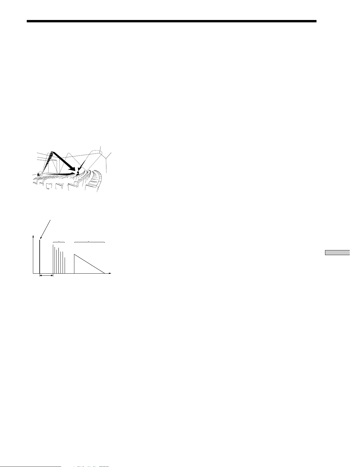
59
Additional Information
Glossary
Surround sound
Sound that consists of three elements:
direct sound, early reflected sound
(early reflections) and reverberative
sound (reverberation). The acoustics
of the surrounding space affect the
way these three sound elements are
heard. Surround sound combines
these sound elements in such a way
that you actually can sense the size of
the venue, as well as its type.
• Types of sound
• Transition of sound from surround
speakers
Dolby Pro Logic Surround
As one method of decoding Dolby
Surround, Dolby Pro Logic Surround
produces four channels from two-
channel sound. Compared with the
former Dolby Surround system,
Dolby Pro Logic Surround reproduces
left-to-right panning more naturally
and localizes sounds more precisely.
To take full advantage of Dolby Pro
Logic Surround, you should have one
pair of surround speakers and a
center speaker. The surround speakers
output monaural sound.
Dolby Digital
This sound format for movie theaters
is more advanced than Dolby Pro
Logic Surround. In this format, the
surround speakers output stereo
sound with an expanded frequency
range and a sub woofer channel for
deep bass is independently provided.
This format is also called “5.1”
because the sub woofer channel is
counted as 0.1 channel (since it
functions only when a deep bass
effect is needed). All six channels in
this format are recorded separately to
realize superior channel separation.
Furthermore, since all the signals are
processed digitally, less signal
degradation occurs.
Digital Cinema Sound
This is the generic name of the
surround sound produced by digital
signal processing technology
developed by Sony. Unlike previous
surround sound fields mainly
directed at the reproduction of music,
Digital Cinema Sound is designed
specifically for the enjoyment of
movies.
Reverberation
Direct sound
Early
reflections
Reverberation
Early reflection time
Early reflections
Direct sound
Time
Level
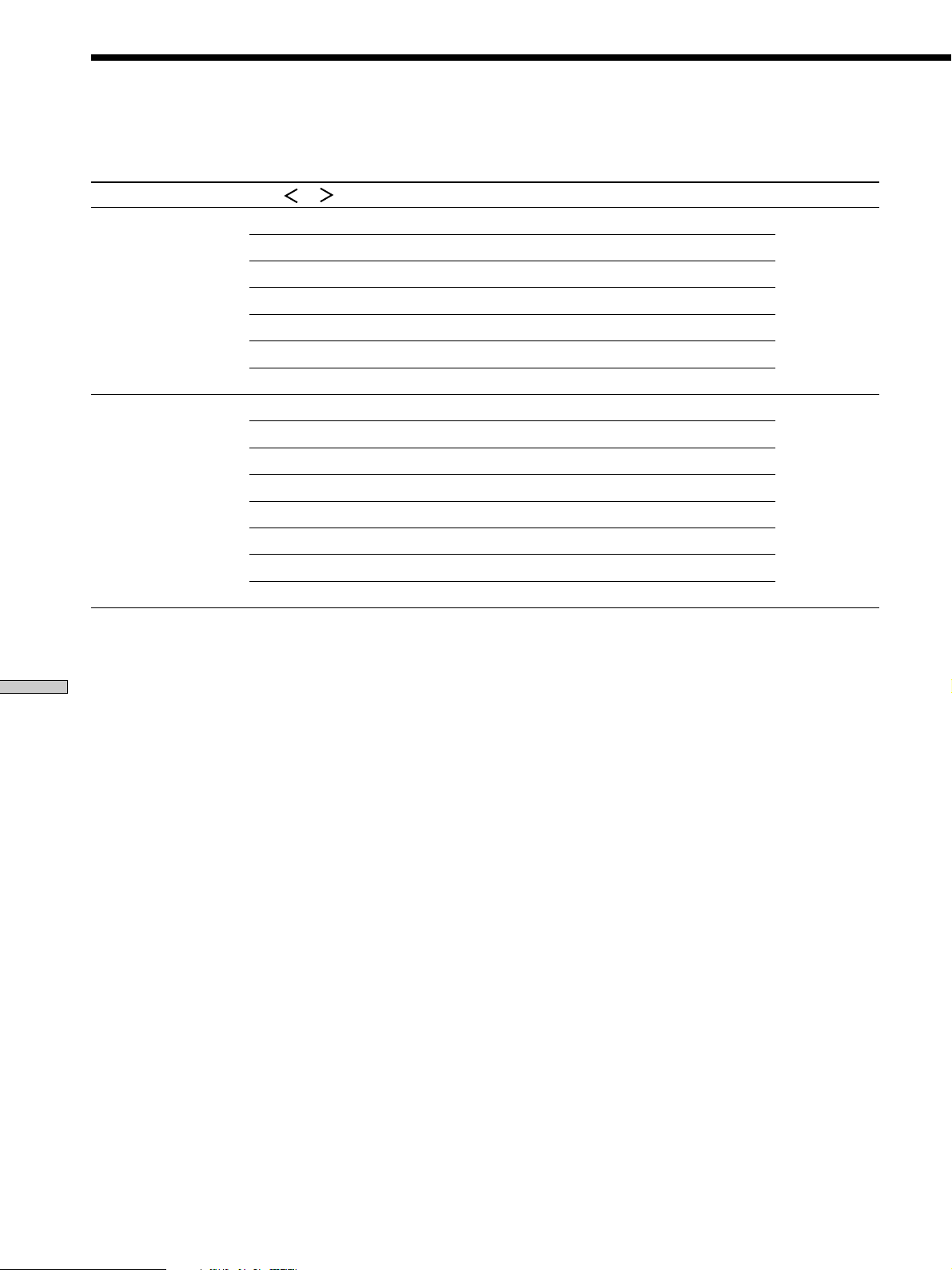
60
Additional Information
Table of settings using SURR, LEVEL, EQ, and SET UP
buttons
Press Press or to select Turn jog dial to select Page
SURR PRO LOGIC AUTO, ON, OFF 36
EFFECT depends on sound field (21 steps)
WALL S__I__H –8 to +8 (1 increment steps)
REVERB S__I__L –8 to +8 (1 increment steps)
FRONT REVERB DRY, WET, STD
SCREEN DEPTH DEEP, MID, OFF
VIR. SPEAKERS ON, OFF
LEVEL FRONT L__I__R –8 dB to +8 dB (1 dB steps) 37
SURROUND L__I__R –8 dB to +8 dB (1 dB steps)
CENTER LEVEL XXX dB –10 dB to +10 dB (1 dB steps)
SURROUND LEVEL XXX dB –10 dB to +10 dB (1 dB steps)
SURR BACK LEVEL XXX dB –10 dB to +10 dB (1 dB steps)
S. WOOFER LEVEL XXX dB –10 dB to +10 dB (1 dB steps)
LFE MIX XXX dB OFF, –20 dB to 0 dB (1 dB steps)
D. RANGE COMP. OFF, 0.1 to 0.9 (0.1 steps), STD, MAX
You can make various settings using the LEVEL, SURR, EQ, SET UP buttons, jog dial, and cursor buttons. The tables below
show each of the settings that these buttons can make.
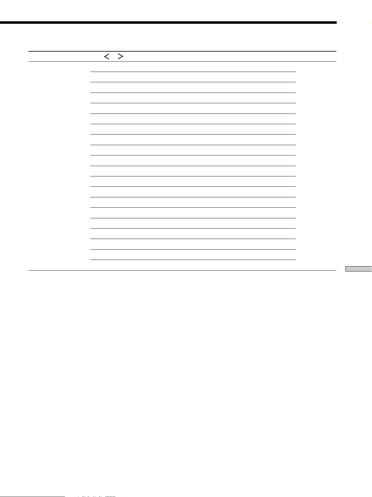
61
Additional Information
Press Press or to select Turn jog dial to select Page
EQ FRONT BASS GAIN –10 dB to +10 dB (1 dB steps) 38
FRONT BASS FREQUENCY 99 Hz to 1.0 kHz (21 steps)
FRONT MID GAIN –10 dB to +10 dB (1 dB steps)
FRONT MID FREQUENCY 198 Hz to 10.0 kHz (37 steps)
FRONT TREBLE GAIN –10 dB to +10 dB (1 dB steps)
FRONT TREBLE FREQUENCY 1.0 kHz to 10 kHz (23 steps)
CENTER BASS GAIN –10 dB to +10 dB (1 dB steps)
CENTER BASS FREQUENCY 99 Hz to 1.0 kHz (21 steps)
CENTER MID GAIN –10 dB to +10 dB (1 dB steps)
CENTER MID FREQUENCY 198 Hz to 10 kHz (37 steps)
CENTER TREBLE GAIN –10 dB to +10 dB (1 dB steps)
CENTER TREBLE FREQUENCY 1.0 kHz to 10 kHz (23 steps)
SURROUND BASS GAIN –10 dB to +10 dB (1 dB steps)
SURROUND BASS FREQUENCY 99 Hz to 1.0 kHz (21 steps)
SURROUND TREBLE GAIN –10 dB to +10 dB (1 dB steps)
SURROUND TREBLE FREQUENCY 1.0 kHz to 10 kHz (23 steps)
SURROUND BACK BASS GAIN –10 dB to +10 dB (1 dB steps)
SURROUND BACK BASS FREQUENCY 99 Hz to 1.0 kHz (21 steps)
SURROUND BACK TREBLE GAIN –10 dB to +10 dB (1 dB steps)
SURROUND BACK TREBLE FREQUENCY 1.0 kHz to 10 kHz (23 steps)
62
Additional Information
Press Press or to select Turn jog dial to select Page
SET UP button FRONT LARGE, SMALL 19
CENTER LARGE, SMALL, NO
SURROUND LARGE, SMALL, NO
SURR BACK LARGE, SMALL, NO
SUB WOOFER YES, NO
FRONT XX.X feet 3 feet to 40 feet (1 foot steps)
CENTER XX.X feet 3 feet to 40 feet (1 foot steps)
SURROUND XX.X feet 3 feet to 40 feet (1 foot steps)
SURR BACK XX.X feet 3 feet to 40 feet (1 foot steps)
SUB WOOFER XX.X feet 3 feet to 40 feet (1 foot steps)
S.W PHASE NORMAL, REVERSE
DISTANCE UNIT feet, meter
SURR POSI. SIDE, MIDDLE, BEHIND
SURR HEIGHT HIGH, LOW
SURR BACK HGT. HIGH, LOW
FRONT SP > XXX Hz
1)
40 Hz to 200 Hz (10 Hz steps)
CENTER SP > XXX Hz
1)
40 Hz to 200 Hz (10 Hz steps)
SURROUND SP > XXX Hz
1)
40 Hz to 200 Hz (10 Hz steps)
SURR BACK SP > XXX Hz
1)
40 Hz to 200 Hz (10 Hz steps)
LFE HIGH CUT > XXX Hz 40 Hz to 200 Hz (10 Hz steps)
6.1CH DECODING AUTO, ON, OFF 51
MULTI CH NONE, Every functions (except for TUNER
and PHONO)
S.FIELD LINK ON, OFF
A1 AUTO POWER ON, OFF
AUTO FUNCTION ON, OFF
COMMAND MODE AV1, AV2
OSD
2)
COLOR, MONOCHROME
OSD H.POSITION
2)
0 to 64 (1 steps)
OSD V.POSITION
2)
0 to 32 (1 steps)
1)
When the speakers are set to SMALL only.
2)
STR-DE975 only.
Table of settings using SURR, LEVEL, EQ, and SET UP buttons
63
Additional Information
You can use the remote to operate the components in your system. The tables below show the settings of each button
common to both remote RM-PP505 and RM-PP505L.
Remote Button Operations Function
SLEEP Receiver Activates the sleep
function and the
duration which the
receiver turns off
automatically.
AV ?/1 TV/VCR/ Turns the audio and
CD player/ video components on or
DVD player/ off.
MD deck/
VCD player/
LD player/
DAT deck
?/1 Receiver
Turns the receiver on or off.
VIDEO 1 Receiver To watch VCR.
(VTR mode 3)
VIDEO 2 Receiver To watch VCR.
(VTR mode 1)
VIDEO 3 Receiver To watch VCR.
(VTR mode 2)
(STR-DE975 only)
DVD/LD Receiver To watch DVD or laser
disc.
TV/SAT Receiver To watch TV programs or
satellite receiver.
CD/SACD Receiver To listen to compact disc.
TUNER Receiver To listen to radio
programs.
PHONO Receiver To listen to turntable.
AV 1 Remote Select the mode of the
remote.
AV 2
2ND ROOM
(STR-DE975 only)
0-9 Receiver
Use with “SHIFT” button
to select tuner preset
station numeric input
during DIRECT TUNING
or MEMORY mode.
CD player/ Selects track numbers.
MD deck/ 0 selects track 10.
VCD player/
LD player/
DAT deck
TV/VCR/SAT Selects channel numbers.
>10 CD player/ Selects tracks numbers
MD deck/ over 10.
Tape deck/
LD player/
VCD player
Remote Button Operations Function
ENTER TV/VCR/SAT/ After selectig a channel,
Tape deck/ disc or track using the
LD player/ numeric buttons, press
VCD player/ to enter the value.
MD deck/
DAT deck
SHIFT Receiver Press repeatedly to select
a memory page for
presetting radio stations
or tuning to preset
stations.
D.TUNING Receiver Tuner station direct key-
in mode.
./> CD player/ Skips tracks.
MD deck/
DVD player/
LD player/
VCD player/
Tape deck/VCR/
DAT deck
m/M CD player/ Searches tracks
DVD player/ (forward or backward).
VCD player
MD deck/ Fastforwards or rewinds.
Tape deck/VCR/
LD player/
DAT deck
n Tape deck Starts play on the
reverse side.
N CD player/ Starts play.
MD deck/Tape
deck/VCR/
DVD player/
VCD player/
LD player/
DAT deck
X CD player/ Pauses play or record.
MD deck/Tape (Also starts recording
deck/VCR/ with components in
DVD player/ record standby.)
VCD player/
LD player/
DAT deck
x CD player/ Stops play.
MD deck/Tape
deck/VCR/
DVD player/
VCD player/
LD player/
DAT deck
Remote Button Description
64
Additional Information
Remote Button Description
Remote Button Operations Function
MULTI /2CH Receiver Selects MULTI CH IN and
A. DIRECT 2CH ANALOG DIRECT
source.
MUTING Receiver Mutes the sound from the
receiver.
AV DISPLAY TV/VCR/ Selects information
LD player/ displayed on the TV
DVD player/ screen.
VCD player
TITLE/GUIDE DVD player Displays title and guide.
VCR/SAT
AV MENU DVD player Displays menu.
VCR/SAT
ON SCREEN Receiver To display the menus of
(STR-DE975 only) the receiver on the TV
screen.
MAIN MENU Receiver Press this button
repeatedly to select one of
the five cursor modes:
LEVEL, SURROUND, EQ,
NAME and SET UP.
U/u/I/i DVD player Selects a menu item.
VCR/SAT
U/u Receiver Selects a menu item.
I/i Receiver Makes adjustment or
change the setting.
ENTER / DVD player/ Enters the selection.
EXEC VCR/SAT
EXIT/RETURN DVD player Returns to the previous
VCR/SAT menu or exits the menu.
MASTER VOL Receiver Adjusts the master
+/– volume of the receiver.
* Only for Sony TVs with the picture-in-picture function.
RM-PP505 only
Remote Button Operations Function
AUX Receiver To listen to an audio
equipment.
MD/TAPE Receiver To listen to Minidisc or
audio tape.
INPUT MODE Receiver Selects input mode for
your digital components.
Notes
• Some functions explained in this section may not work
depending on the model of the receiver.
• The above explanation is intended to serve as an example only.
Therefore, depending on the component the above operation
may not be possible or may operate differently than described.
• The /10, /11, /12, 3RD, NIGHT MODE and AUDIO SPLIT
functions are not available for set operation.
Remote Button Operations Function
DISC CD player/ Select discs (multi-disc
VCD player changer only).
D. SKIP/CH/ Receiver Scans and selects preset
PRESET +/– stations.
TV/VCR/SAT Selects preset channels.
CD player/ Skips discs (multi-disc
VCD player/ changer only).
MD deck
MONITOR TV Press to activate TV
control buttons. Press
again to restore original
category.
TV/VIDEO TV/VCR Selects input signal: TV
input or video input.
SEARCH MODE DVD player Selects searching mode.
CLEAR DVD player Press if you made a
mistake when you press
the number button.
VCD player Press to go back to the
previous menu.
WIDE TV Selects the wide picture
mode.
-/-- TV/VCR Selects the channel entry
mode, either one or two
digit.
ANT TV/VTR VCR Selects output signal from
the aerial terminal: TV
signal or VCR program.
JUMP TV Toggles between the
previous and the current
channels.
SUB CH +/–* TV Selects preset channels for
the small picture.
VOL +/– TV Adjust the volume of TV.
POSITION* TV Changes the position of
the small picture.
MUTING TV Mutes the sound from TV.
(with PAUSE)
SWAP* TV Swaps the small and the
large picture.
P IN P* TV Activates the picture-in-
picture function.
A. F. D. Receiver Auto Format Decoding.
MODE +/– Receiver Selects sound field mode.
2CH Receiver Selects 2CH mode.
PRESET Receiver Selects CINEMA STUDIO
EX A, B, C, DIGITAL
CONCERT HALL A or B.
TEST TONE Receiver Press to output test tone.
EQ/TONE Receiver EQ ON/OFF.
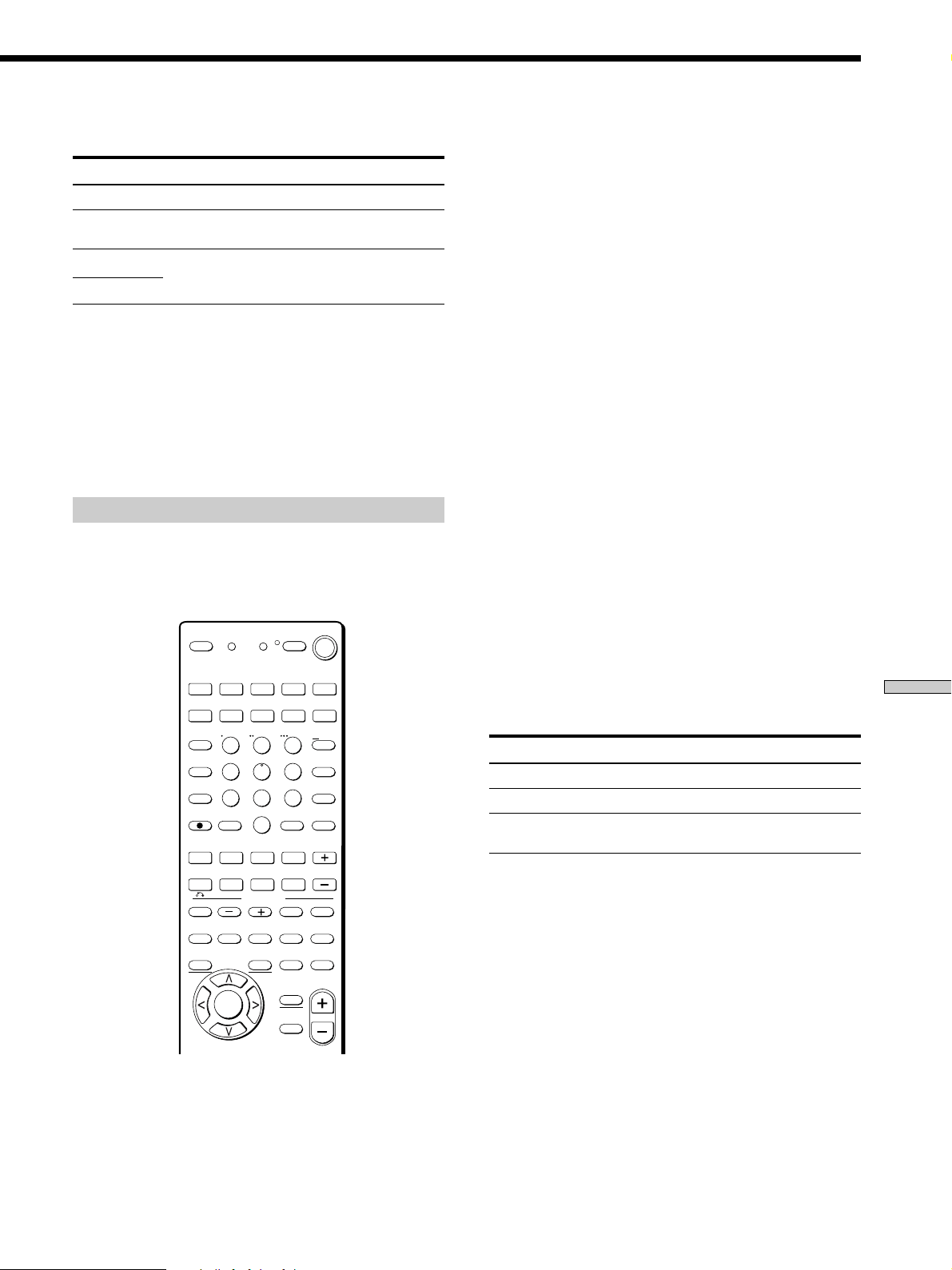
65
Additional Information
RM-PP505L only
Remote Button Operations Function
TAPE Receiver To listen to audio tape.
MD/DAT Receiver To listen to Minidisc or
DAT.
MACRO 1 Receiver To perform several
commands in sequence
automatically.
Notes
• Some functions explained in this section may not work
depending on the model of the receiver.
• The above explanation is intended to serve as an example only.
Therefore, depending on the component the above operation
may not be possible or may operate differently than described.
• The /10, /11, /12, 3RD, NIGHT MODE and AUDIO SPLIT
functions are not available for set operation.
RM-PP505 and RM-PP505L
Selecting the mode of the remote
Set the remote mode using the USE MODE button and the
remote mode buttons.
RM-PP505
Selecting the command mode
You can switch the command mode (AV1 or AV2) of the
remote. If the command mode of the receiver and the
remote is different, you cannot use the remote to operate
the receiver.
Press 1 (AV1) (or 2 (AV2)) while pressing down USE
MODE.
The indicator lights once (twice for AV2), then the
command mode switches.
Setting to the 2nd room mode. (STR-DE975 only)
You can use the remote to select the function for the 2nd
room (2nd room mode). You can use the function buttons
only for the 2nd room.
Press 2ND ROOM while pressing down USE MODE.
(STR-DE975 only)
The indicator lights for a while, then the mode switches to
the 2nd room mode.
Tips (STR-DE975 only)
• If you press a function button while pressing down 2ND
ROOM, you can select the function for the 2nd room even
though the mode is not set to the 2nd room mode.
• If you press 2ND ROOM only, you can output the source signal
of the current function of the receiver to the amplifier in the
2nd room.
To check the mode of the remote
Press USE MODE. You can check the remote by the
indicator.
Mode Indicator lights
AV1 once
AV2 twice
2nd room once (for a while)
(STR-DE975 only)
To reset the remote to factory settings
Press ?/1, AV ?/1, and MASTER VOL – at the same
time.
The indicator lights 3 times, then goes off.
MACRO 2
>10
1
4
7
2
5
8
3
6
9
0
MONITOR
2ND ROOM
VIDEO 1 VIDEO 2 VIDEO 3 DVD/LD TV/SAT
AUX
TV/VIDEO
INPUT MODE
CLEAR
– SUB CH +
– VOL +
POSITION SWAP
SEARCH
MODE
AUDIO
SPLIT
ENTER
ANT
TV/VTR
D. SKIP/
CH/PRESET
MD/TAPE CD/SACD TUNER PHONO
SHIFT
DISC
JUMP
A.F.D.
AV
DISPLAY
TEST
TONE
NIGHT
MODE
ON
SCREEN
MAIN
MENU
EXIT/
RETURN
AV
MENU
TITLE
GUIDE
ENTER/
EXEC
MULTI/2CH
A. DIRECT
EQ/TONE
MUTING
MUTING
MODE
2CH
PRESET
P IN P
– /– –
SOUND FIELD
D.TUNING
AV1 AV2 3RD
(SOURCE)
WIDE
/11 /10 /12
SLEEP
? / 1
SYSTEM
STANDBY
USE MODE
MASTER
VOL
.Mm
nN
X
>
x
AV
? / 1

66
Additional Information
Remote Button Description
Programming the remote
You can program the remote to control non-Sony
components by changing the code. Once the control
signals have been memorized, you can use those
components as part of your system.
Furthermore, you can also program the remote for Sony
components that the remote is unable to control. Note that
the remote can only control components that accept
infrared wireless control signals.
Note
When you assign a component to the MONITOR button, you can
operate the programmed component without changing the
function of the receiver.
1 Press AV ?/1 while pressing down USE MODE.
The indicator lights.
2 Press the function button (including MONITOR) for
the component you want to control.
For example, if you are going to control a CD player,
press CD.
3 Press the numeric buttons to enter the numeric
code (or one of the codes if more than one code
exists) corresponding to the component and the
maker of the component you want to control.
See the tables on pages 67 and 68 for information on
the numeric code(s) corresponding to the component
and the maker of the component (the first digit and
the last two digits of the numeric code correspond to
the category and the maker’s code respectively.)
4 Press ENTER.
Once the numeric code has been verified, the indicator
slowly flashes twice and the remote automatically
exits the programming mode.
5 Repeat steps 1 to 4 to control other components.
To cancel programming
Press USE MODE during any step. The remote
automatically exits the programming mode.
z To activate the function after programming.
Press the programmed button to activate the function you want.
z If programming is unsuccessful, check the following:
• If the indicator does not light up in step 1, the batteries are
weak. Replace both batteries.
• If the indicator flashes 4 times in quick succession while
entering the numeric code, an error has occurred. Start again
from step 1.
Notes
• The indicator turns off while a valid button is pressed.
• In step 2, if several function buttons are pressed, only the last
pressed button is valid.
• In step 3, if a function button is pressed, the new function is
selected and the programming procedure returns to the
beginning of step 3.
• For the numeric codes, only the first three numbers entered are
valid.
To clear the memory of the remote
To clear all programmed and learned signals, do the
following to reset the remote to factory settings.
Press ?/1, AV ?/1 and MASTER VOL – at the same
time.
The indicator flashes 3 times, then goes off.
The numeric codes corresponding to the
component and the maker of the component
Use the numeric codes in the tables below to control non-
Sony conponents and also Sony components that the
remote is normally unable to control. Since the remote
signal that a component accepts differs depending on the
model and year of the component, more than one numeric
code may be assigned to a component. If you fail to
program your remote using one of the codes, try using
other codes.
Notes
• The numeric codes are based on the latest information available
for each brand. There is a chance, however, that your
component will not respond to some or all of the codes.
• All of the functions on this remote may not be available when
used with your particular component.

67
Additional Information
To control an LD player
Maker Code(s)
SONY 601, 602, 603
PIONEER 606
To control a video CD player
Maker Code(s)
SONY 605
To control a VCR
Maker Code(s)
SONY 701, 702, 703, 704, 705, 706
AIWA 710, 750, 757, 758
AKAI 707, 708, 709, 759
BLAUPUNKT 740
EMERSON 711, 712, 713, 714, 715, 716, 750
FISHER 717, 718, 719, 720
GENERAL ELECTRIC 721, 722, 730
GOLDSTAR 723, 753
GRUNDIG 724
HITACHI 722, 725, 729, 741
ITT/NOKIA 717
JVC 726, 727, 728, 736
MAGNAVOX 730, 731, 738
MITSUBISHI/MGA 732, 733, 734, 735
NEC 736
PANASONIC 729, 730, 737, 738, 739, 740
PHILIPS 729, 730, 731
PIONEER 729
RCA/PROSCAN 722, 729, 730, 731, 741, 747
SAMSUNG 742, 743, 744, 745
SANYO 717, 720, 746
SHARP 748, 749
TELEFUNKEN 751, 752
TOSHIBA 747, 755, 756
ZENITH 754
To control a CD player
Maker Code(s)
SONY 101, 102, 103
DENON 104, 123
JVC 105, 106, 107
KENWOOD 108, 109, 110
MAGNAVOX 111, 116
MARANTZ 116
ONKYO 112, 113, 114
PANASONIC 115
PHILIPS 116
PIONEER 117
TECHNICS 115, 118, 119
YAMAHA 120, 121, 122
To control a DAT deck
Maker Code(s)
SONY 203
PIONEER 219
To control an MD deck
Maker Code(s)
SONY 301
DENON 302
JVC 303
KENWOOD 304
To control a tape deck
Maker Code(s)
SONY 201, 202
DENON 204, 205
KENWOOD 206, 207, 208, 209
NAKAMICHI 210
PANASONIC 216
PHILIPS 211, 212
PIONEER 213, 214
TECHNICS 215, 216
YAMAHA 217, 218
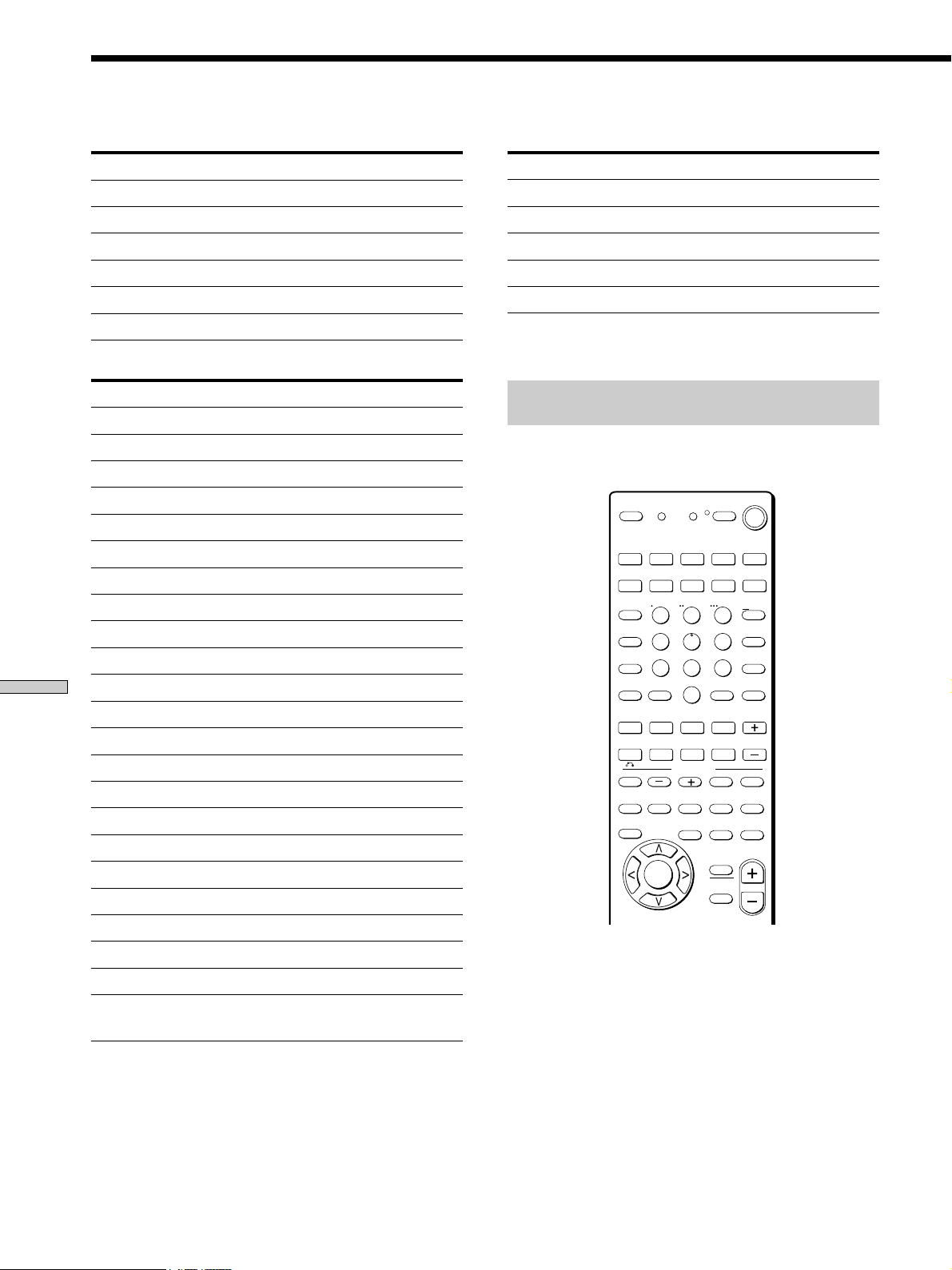
68
Additional Information
Remote Button Description
>10
1
4
7
2
5
8
3
6
9
0
MONITOR
2ND ROOM
VIDEO 1 VIDEO 2 VIDEO 3 DVD/LD TV/SAT
TAPE
TV/VIDEO
MACRO 1
CLEAR
– SUB CH +
– VOL +
POSITION SWAP
SEARCH
MODE
MACRO 2
ENTER
ANT
TV/VTR
D. SKIP/
CH/PRESET
MD/DAT CD/SACD TUNER PHONO
SHIFT
DISC
JUMP
A.F.D.
AV
DISPLAY
TEST
TONE
NIGHT
MODE
ON
SCREEN
MAIN
MENU
EXIT/
RETURN
AV
MENU
TITLE
GUIDE
ENTER/
EXEC
MULTI/2CH
A. DIRECT
EQ/
TONE
MUTING
MUTING
MODE
2CH
PRESET
P IN P
– /– –
SOUND FIELD
D.TUNING
AV1 AV2 3RD
(SOURCE)
WIDE
/11 /10 /12
SLEEP
AV
? / 1
? / 1
SYSTEM
STANDBY
USE MODE
MASTER
VOL
.Mm
nN
X
>
x
To control a DVD player
Maker Code(s)
SONY 401
PANASONIC 402, 406
PHILIPS 407
PIONEER 403
TOSHIBA 404
DENON 405
To control a TV
Maker Code(s)
SONY 501
DAEWOO 504, 505, 506, 507, 515, 544
FISHER 508
GOLDSTAR 503, 511, 512, 515, 534, 544
GRUNDIG 517, 534
HITACHI 513, 514, 515, 544
ITT/NOKIA 521, 522
JVC 516
MAGNAVOX 503, 518, 544
MITSUBISHI/MGA 503, 519, 544
NEC 503, 520, 544
PANASONIC 509, 524
PHILIPS 515, 518
PIONEER 509, 525, 526, 540
RCA/PROSCAN 510, 527, 528, 529, 544
SAMSUNG 503, 515, 531, 532, 533, 534, 544
SANYO 508, 545
SHARP 535
TELEFUNKEN 523, 536, 537, 538
THOMSON 530, 537, 539
TOSHIBA 535, 540, 541
ZENITH 542, 543
To control a satellite tuner or cable box
Maker Code(s)
SONY 801, 802, 803
JERROLD/G.I. 806, 807, 808, 809, 810, 811, 812, 813, 814
PANASONIC 818
RCA 804, 805
S. ATLANTA 815, 816, 817
RM-PP505L only
Learning the commands of your
components
By using the Learning function, it is possible for this
remote to perform learned commands.
69
Additional Information
5-15 cm
Setting remote control codes that are not stored
in the remote
When a remote control code is not one of the presets
stored in the remote, it is possible for the remote to learn
the code using the Learning function.
1 Press SLEEP while pressing down USE MODE.
The indicator lights.
2 Press the function button for the component you
want to learn functions for.
For example, if you are going to learn an operation for
a CD player, press CD.
3 Press the button you want to use for the Learning
function.
The indicator turns off while a valid button is pressed,
then blinks slowly.
4 Point the remote control code receiver section of
the remote toward the receiver/transmitter on the
remote control to be learned.
5 Press the appropriate button on the remote control
to be learned to send the remote button code.
Lightly pressing the button once should be sufficient.
If learning is completed successfully, the indicator
slowly flashes twice and the remote automatically
exits the learning mode.
When learning is not completed successfully, the
indicator flashes 4 times in quick succession and the
procedure returns to step 5.
If the memory of the remote is already full, the
indicator flashes 8 times in quick succession and the
remote automatically exits the learning mode.
Notes
• You can program up to 80 buttons for the Learning function. In
some cases, you may not be able to program even if you have
not programmed 80 buttons.
• In steps 2 and 3, the indicator turns off while a valid button is
pressed.
• In step 3, if several buttons that can be used for learning are
pressed, only the last pressed button is valid.
• In step 5, if a button that can be used for learning is pressed, the
new button is selected and the learning procedure returns to
the beginning of step 5.
• You can use TV/VIDEO only for the MONITOR function.
z To activate the function after programming.
Press the programmed button to activate the function you want.
To cancel learning
Press USE MODE during any step. The remote
automatically exits the learning mode.
To clear the learned codes
Start over from step 1. After step 3, press SLEEP for more
than 2 seconds. The indicator lights twice slowly and the
learned code is cleared. If SLEEP is pressed less than 2
seconds, the learning procedure returns to the beginning
of step 5.
When a learned code is cleared, if the button was
previously programmed for another function, the
programmed code for that button can be used.
To clear the memory of the remote
To clear all programmed and learned signals, do the
following to reset the remote to factory settings.
At the same time, press ?/1, AV ?/1, and MASTER
VOLUME.
The indicator flashes 3 times, then goes off.
To use a command that has been learned
When selecting a learned function, press the learned
button for that function.
.Mm
nN
X
>
x

70
Additional Information
Performing several commands in
sequence automatically (Macro Play)
The Macro Play function lets you link several IR codes in
a sequential order as a single command. The remote
provides 2 macro lists (MACRO1 and 2). You can specify
up to 10 IR codes for each macro list.
Setting the sequence of IR codes
1 Press MACRO1 (or MACRO2) while pressing down
USE MODE.
The indicator lights.
2 Press the numeric buttons to select the macro step
number.
For example, to program step 1, press 1.
3 Press the button you want to program.
To program the operation (IR code) of a
component connected to the receiver, press
the function button (including MONITOR) first,
then press the button for the operation.
For example, to play the CD player, press CD, then
press H.
When programmed successfully, the indicator lights
twice slowly, then the remote automatically exits the
macro setting mode.
To program the operation (IR code) of the
receiver, press the button for the operation.
Buttons that can be programmed:
SLEEP, ?/1, 2ND ROOM, A.F.D., MODE +/–, 2CH,
PRESET, TEST TONE, NIGHT MODE, EQ, MULTI/
2CH A. DIRECT, ON SCREEN, MUTING, MAIN
MENU, MASTER VOL +/–
When programmed successfully, the indicator lights
twice slowly, then the remote automatically exits the
macro setting mode.
4 Repeat steps 1 through 3 to program up to 10 IR
codes.
Tips
• To program a function switch, press the same function button
twice in step 3.
• If programming is unsuccessful, check the following:
– If the indicator does not light up in step 1, the batteries are
weak. Replace both batteries.
– If the indicator lights 4 times in quick succession in step 3, an
error has occured. Start again from step 1.
Note
The indicator turns off while a valid button is pressed.
Remote Button Description
To cancel programming
Press USE MODE during any step. The remote
automatically exits the macro setting mode.
To delay the output of an IR code
Start over from step 1. In step 3, press VIDEO 1, then
MACRO1 or MACRO2. This allows you to specify 1
second delay before output the next IR code. Be sure not
to press MACRO1 or MACRO2 for more than 2 seconds.
To clear the programmed IR codes
Clear each macro step individually.
1 Press MACRO1 or MACRO2 (in which the IR code
you want to clear is programmed) while pressing
down USE MODE.
2 Press the numeric button to select the macro step
number you want to clear.
3 Press VIDEO 1.
4 Hold down MACRO1 or MACRO2 for more than 2
seconds.
The IR code is cleared. The indicator lights twice
slowly, then the remote automatically exits the macro
setting mode.
To start macro play
Press MACRO1 (or MACRO2).
Note
If the Macro Play function does not work properly, program a
delay between each operation. See “To delay the output of an IR
code”.

71
Additional Information
Index
A
Adjusting
brightness of the display 25
speaker volumes 23
surround parameters 36
Automatic tuning 4
B
Basic receiver operations
25 – 29
Batteries 4
C
Changing
display 25
effect level 36
Checking the connections 24
Clearing receiver’s memory 18
Connecting. See Hookups
CONTROL A1
13, 53
Customizing sound fields 36
D
Demonstration mode 18
Digital Cinema Sound 59
Direct tuning 46
Dolby Digital 59
Dolby Pro Logic Surround 59
Dubbing. See Recording
E, F, G
Editing. See Recording
Effect level 36
H
Hookups
MULTI CH IN Input 11
AC power cord 14
antennas 5
audio components 6
digital components 9
CONTROL A1
13
speaker system 15
video components 8
I, J, K
Indexing. See Naming
L, M
Labeling. See Naming
N, O
Naming
preset stations 49
program sources 49
P, Q
Parameter 36, 39
Preset stations
how to preset 47
how to tune 46
Preset tuning 47
R
Receiving broadcasts
automatically 46
directly 46
preset stations 47
Recording
on an audio tape or MD 49
on a video tape 50
S
Scanning
preset stations. See Preset
tuning
radio stations. See Automatic
tuning
Selecting
component 27
sound field 31
Sleep timer 50
Sound field
adjustable parameters 39
customizing 38
pre-programmed 28 – 31
resetting 38
selecting 31
Speakers
adjusting speaker volume 23
connection 16
placement 19
Supplied accessories 4
Surround sound 30 – 43
T
Test tone 23
Troubleshooting 55
Tuning
automatically 46
directly 46
preset stations 47
U, V, W, X, Y, Z
Unpacking 4

Sony Corporation Printed in Malaysia http://www.world.sony.com/