Loading ...
Loading ...
Loading ...
11
Connecting Components
The MA352 has the ability to automatically switch
power On/Off to McIntosh Source Components via
the Power Control connections. The Data Port Con-
nections allow for the remote operation of basic func-
tions using the MA352 Remote Control.
The connection instructions below, together with
the MA352 Input and Output Connection Diagrams
located on the separate folded sheets “Mc2A/2B” and
“Mc3A”, are examples of typical audio systems. Your
system may vary from this, however the actual com-
ponents would be connected in a similar manner. For
additional information refer to “Connector and Cable
Information” on page 6.
Power Control Connections:
1. Connect a Control Cable from the MA352
POWER CONTROL OUTPUT Jack to the Power
Control In on the Turntable.
2. Connect a Control Cable from the Turntable Pow-
er Control Out Jack to the Media Bridge Power
Control In Jack.
3. Connect a Control Cable from the Media Bridge
Power Control Out Jack to the AM/FM Tuner
Power Control In Jack.
4. Connect a Control Cable from the AM/FM Tuner
Power Control Out Jack to the SACD/CD Player
Power Control In Jack.
5. Optionally, connect the SACD/CD Player Power
Control out Jack to the Secondary Power Ampli-
fier PWR CTRL.
6. Optionally, connect the A/V Processer Zone A
Power Control to the MA352 PASSTHRU POW-
ER CONTROL input Jack.
7. Connect any additional McIntosh Components in a
similar manner, as outlined in steps 1 thru 3.
Data Control Connections:
8. Connect a Control Cable from the MA352 DATA
PORTS 1 Jack to the SACD/CD Player Data In
Jack.
9. Connect a Control Cable from the MA352 DATA
PORTS 2 Jack to the AM/FM Tuner Data In Jack.
Audio Connections:
10. Connect XLR Balanced Cables from the MA352
BALanced INPUT 1 Connectors to the Media
Bridge Audio Output Balanced Connectors.
11. Connect the Audio Cables from the AM/FM Tuner
UNBAL Connectors to the MA352 UNBAL-
ANCED 1 Connectors.
12. Connect the Audio Cables from the SACD/CD
Player UNBAL Connectors to the MA352 UN-
BALANCED 2 Connectors.
13. Connect the Audio Cables from the Turntable
PHONO OUT Jacks to the MA352 MM PHONO
Connectors.
14. Connect any additional Components in a similar
manner, as outlined in steps 7 thru 12.
15. Optionally, connect the A/V Processer Left Front
and Right Front XLR Connectors to the MA352
2L and 2R Balanced XLR Connectors.
Ground Connections:
16. Connect the Ground Cable coming from the Turn-
table to the MA352 GND Binding Post.
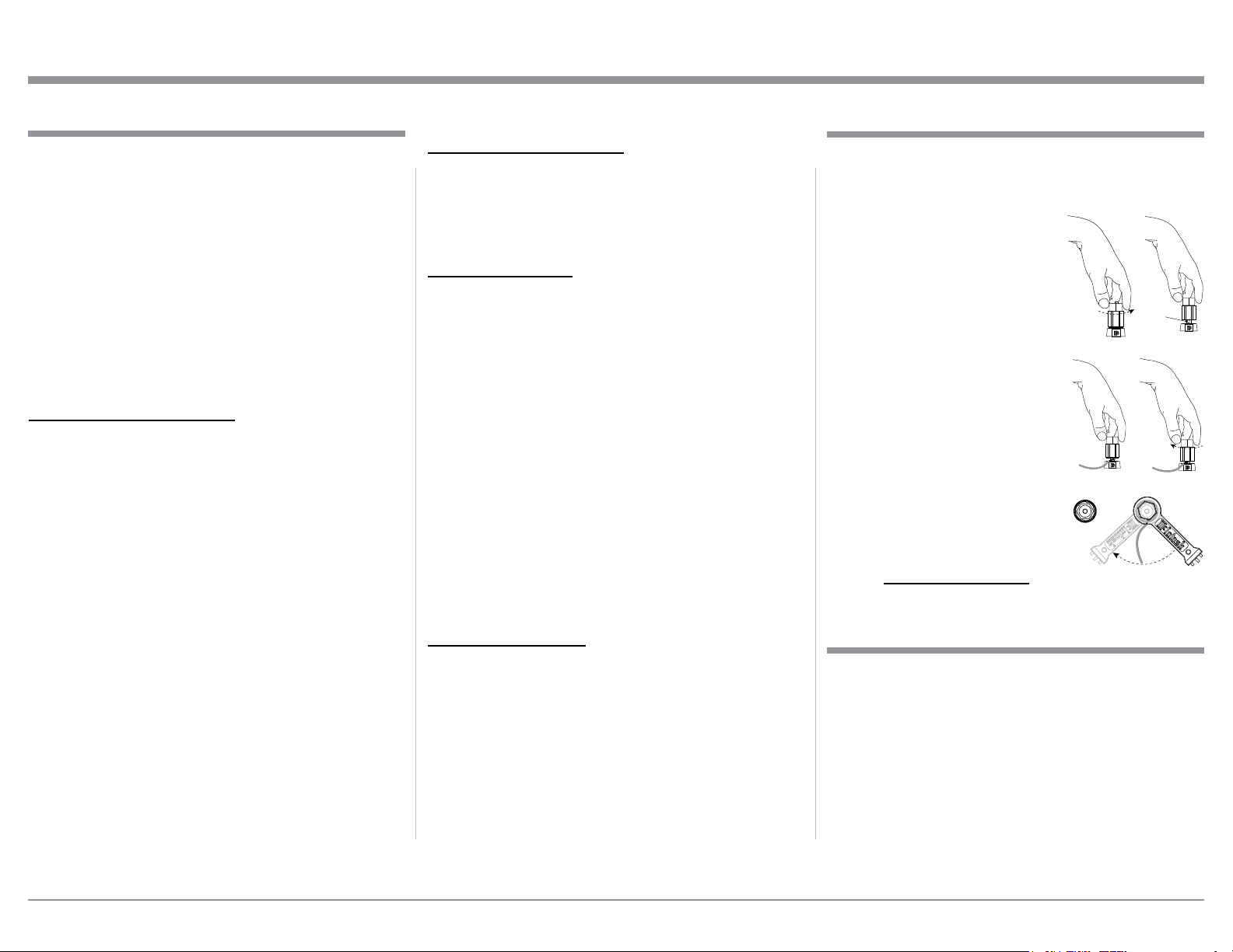
Output Terminals
When connecting the Loudspeaker Hookup Cables to
the MA352 Amplifier Output Terminals please follow
the steps below:
1. Rotate the top of the Output Terminal Post coun-
terclockwise until an opening
appears. Refer to gures A and
B.
2. Insert the Loudspeaker hookup
cable into the Output Terminal
Post opening or the cable spade
lug around the center post of
the Output Terminal. Refer to
gure C.
3. Rotate the top of the Output
Terminal Post clockwise until it
is nger tight. Refer to gure D.
4. Place the supplied McIntosh
Wrench over the top of the Out-
put Terminal and rotate it one
quarter of a turn (90°) to secure
the Loudspeaker Cable Connec-
tion. Do not over tighten. Refer
to gure E.
Figure A
Opening
Figure B
Figure C Figure D
Figure E
Connecting Components
How to Connect Loudspeakers
Caution: Do not connect the AC Power Cord to the
MA352 Rear Panel until after the Loudspeaker
Connections are made. Failure to observe this
could result in Electric Shock.
The MA352 Connection Instructions, located on the
next page together with the Separate Diagram Sheets,
are for a typical audio system. Your system may vary
from this, however the actual components would be
connected in a similar manner. For additional infor-
mation refer to “Connector and Cable Information” on
page 6.
Loading ...
Loading ...
Loading ...