English-2
Features of your new air conditioner
2-step cooling
2-step cooling function will quickly cool the room to reach the desired temperature and then it
will adjust the fan speed and air flow direction automatically to help you stay comfortable and
refreshing.
Fast cooling/heating
If you want the strong and cool/warm air, just select Fast function! It will get you the strongest air!
Comfort cooling/heating
If you want the comfortable and refreshing air, Comfort function will spread the cool/warm air
indirectly to you, so that you can stay comfortable.
Single User
Use Single User function when you are alone at home. Single User function will minimize the
energy consumption with inverter technology and reduce your electricity bill by adjusting the
maximum operating capacity of the compressor.
function
function will allow you to have deep, good night’s sleep by adjusting the
temperature, fan speed and air ow direction.
English-3
Contents
Preparation
Safety precautions ..........................................................................................................4
Checking before use ......................................................................................................10
Basic function
Checking the name of the parts ...........................................................................................11
Checking the remote controller ...........................................................................................12
Basic function .............................................................................................................14
Adjusting the air ow direction............................................................................................17
Timer
Setting the Current time...................................................................................................18
Setting the On/O timer ..................................................................................................19
mode .........................................................................................................21
Options
Using the Fast function....................................................................................................22
Using the Comfort function ...............................................................................................22
Using the Single User function ............................................................................................23
2-Step cooling function ...................................................................................................24
Using the d'light Cool function ............................................................................................24
Using the Quiet function ..................................................................................................25
Settings
Using the Auto clean function .............................................................................................26
Checking the power consumption.........................................................................................26
Setting the Display option.................................................................................................27
Setting the Beep sound ...................................................................................................27
Resetting the Filter clean reminder ........................................................................................27
Others
Cleaning the air conditioner............................................................................................... 28
Maintaining the air conditioner............................................................................................30
Troubleshooting ..........................................................................................................31
Installation
Safety precautions ........................................................................................................33
Choosing the installation location .........................................................................................34
Accessories ...............................................................................................................38
Fixing the installation plate................................................................................................39
Connecting the assembly cable ...........................................................................................40
Installing and connecting the assembly pipe of the indoor unit ............................................................43
Evacuating the indoor unit ................................................................................................44
Cutting or extending the pipe .............................................................................................44
Installing and connecting the drain hose of the indoor unit ................................................................46
Changing direction of the drain hose ......................................................................................47
Installing and connecting the drain hose of the outdoor unit ..............................................................48
Evacuating the connected pipes...........................................................................................48
Performing the gas leak tests..............................................................................................51
Fixing the indoor unit in place.............................................................................................52
Fixing the outdoor unit in place ...........................................................................................52
Final check and trial operation.............................................................................................53
Pump down procedure (when removing the product) . . . . . . . . . . . . . . . . . . . . . . . . . . . . . . . . . . . . . . . . . . . . . . . . . . . . . . . . . . . . . . . . . . . . . 53
How to connect your extended power cables..............................................................................54
English-4
Safety precautions
Before using your new air conditioner, please read this manual thoroughly to ensure
that you know how to safely and eciently operate the extensive features and
functions of your new appliance.
Because the following operating instructions cover various models, the
characteristics of your air conditioner may dier slightly from those described in this
manual. If you have any questions, call your nearest contact center or nd help and
information online at www.samsung.com.
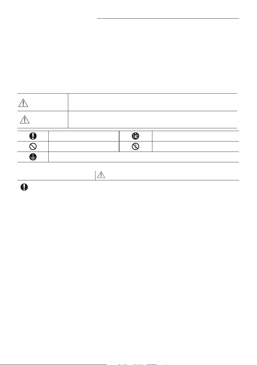
Important safety symbols and precautions:
WARNING
Hazards or unsafe practices that may result in severe
personal injury or death.
CAUTION
Hazards or unsafe practices that may result in minor
personal injury or property damage.
Follow directions. Cut-o the power supply.
Do NOT attempt. Do NOT disassemble.
Make sure the machine is grounded to prevent electric shock.
FOR INSTALLATION
WARNING
Use the power line with the power specications of the product or higher
and use the power line for this appliance only. In addition, do not use an
extension line.
Extending the power line may result in electric shock or fire.
Do not use an electric transformer. It may result in electric shock or fire.
If the voltage/frequency/rated current condition is different, it may cause
fire.
The installation of this appliance must be performed by a qualied
technician or service company.
Failing to do so may result in electric shock, fire, explosion, problems with the
product, or injury and may also void warranty on the installed product.
Install a Isolation Switch next to the Air Conditioner (but not on the panels
of the Air Conditioner)and circuit breaker dedicated to the air conditioner.
Failing to do so may result in electric shock or fire.
Fix the outdoor unit rmly so that the electric part of the outdoor unit is not
exposed.
Failing to do so may result in electric shock, fire, explosion, problems with the
product.
Preparation
English-5
PREPARATION01
Do not install this appliance near a heater, inammable material. Do
not install this appliance in a humid, oily or dusty location, in a location
exposed to direct sunlight and water (rain drops). Do not install this
appliance in a location where gas may leak.
This may result in electric shock or fire.
Never install the outdoor unit in a location such as on a high external wall
where it could fall.
If the outdoor unit falls, it may result in injury, death or property damage.
This appliance must be properly grounded. Do not ground the appliance to a
gas pipe, plastic water pipe, or telephone line.
Failure to do so may result in electric shock, fire, and explosion.
Make sure to use a socket-outlet with ground.
FOR INSTALLATION
CAUTION
Install your appliance on a level and hard oor that can support its weight.
Failing to do so may result in abnormal vibrations, noise, or problems with the
product.
Install the draining hose properly so that water is drained correctly.
Failing to do so may result in water overflowing and property damage. Avoid
adding drain to waste pipes as odours may arise in the future.
When installing the outdoor unit, make sure to connect the draining hose
so that draining is performed correctly.
The water generated during the heating operation by the outdoor unit may
overflow and result in property damage.
In particular, in winter, if a block of ice falls, it may result in injury, death or
property damage.
FOR POWER SUPPLY
WARNING
When the circuit breaker is damaged, contact your nearest service center.
Do not pull or excessively bend the power line. Do not twist or tie the
power line. Do not hook the power line over a metal object, place a heavy
object on the power line, insert the power line between objects, or push
the power line into the space behind the appliance.
This may result in electric shock or fire.
English-6
Safety precautions
FOR POWER SUPPLY
CAUTION
When not using the air conditioner for a long period of time or during a
thunder/lightning storm, cut the power at the circuit breaker.
Failing to do so may result in electric shock or fire.
FOR USING
WARNING
If the appliance is ooded, please contact your nearest service center.
Failing to do so may result in electric shock or fire.
If the appliance generates a strange noise, a burning smell or smoke, cut-
o the power supply immediately and contact the nearest service center.
Failing to do so may result in electric shock or fire.
In the event of a gas leak (such as propane gas, LP gas, etc.), ventilate
immediately without touching the power line. Do not touch the appliance
or power line.
Do not use a ventilating fan.
A spark may result in an explosion or fire.
To reinstall the air conditioner, please contact your nearest service center.
Failing to do so may result in problems with the product, water leakage,
electric shock, or fire.
A delivery service for the product is not provided. If you reinstall the product in
another location, additional construction expenses and an installation fee will
be charged.
Especially, when you wish to install the product in an unusual location such as
in an industrial area or near the seaside where it is exposed to the salt in the air,
please contact your nearest service center.
Please refer to your warranty cards for terms and conditions.
Do not touch the circuit breaker with wet hands.
This may result in electric shock.
Do not turn the air conditioner o with the circuit breaker while it is
operating.
Turning the air conditioner off and then on again with the circuit breaker may
cause a spark and result in electric shock or fire.
After unpacking the air conditioner, keep all packaging materials well
out of the reach of children, as packaging materials can be dangerous to
children.
If a child places a bag over its head, it may result in suffocation.
English-7
PREPARATION01
Do not insert your ngers or foreign substances into the outlet when the air
conditioner is operating.
Take special care that children do not injure themselves by inserting their
fingers into the product.
Do not touch the air ow blade with your hands or ngers during the
heating operation.
This may result in electric shock or burns.
Do not insert your ngers or foreign substances into the air inlet/outlet of
the air conditioner.
Take special care that children do not injure themselves by inserting their
fingers into the product.
Do not strike or pull the air conditioner with excessive force.
This may result in fire, injury, or problems with the product.
FOR USING
WARNING
Do not place an object near the outdoor unit that allows children to climb
onto the machine.
This may result in children seriously injuring themselves.
Do not use this air conditioner for long periods of time in badly ventilated
locations or near inrm people.
Since this may be dangerous due to a lack of oxygen, Open a window at least
once an hour.
If any foreign substance such as water has entered the appliance, cut-o
the power supply and contact the nearest service center.
Failing to do so may result in electric shock or fire.
Do not attempt to repair, disassemble, or modify the appliance yourself.
Do not use any fuse (such as cooper, steel wire, etc.)other than the standard
fuse.
Failing to do so may result in electric shock, fire, problems with the product, or
injury.
English-8
Safety precautions
FOR USING
CAUTION
Do not place objects or devices under the indoor unit.
Water dripping from the indoor unit may result in fire or property damage.
(example electrical appliances)
Check that the installation frame of the outdoor unit is not broken at least
once a year.
Failing to do so may result in injury, death or property damage.
Max current is measured according to IEC standard for safety and current is
measured according to ISO standard for energy eciency.
Do not stand on top of the appliance or place objects (such as laundry,
lighted candles, lighted cigarettes, dishes, chemicals, metal objects, etc.) on
the appliance.
This may result in electric shock, fire, problems with the product, or injury.
Do not operate the appliance with wet hands.
This may result in electric shock.
Do not spray volatile material such as insecticide onto the surface of the
appliance.
As well as being harmful to humans, it may also result in electric shock, fire or
problems with the product.
Do not drink the water from the air conditioner.
The water may be harmful to humans.
Do not apply a strong impact to the remote controller and do not
disassemble the remote controller.
Do not touch the pipes connected with the product.
This may result in burns or injury.
Do not use this air conditioner to preserve precision equipment, food,
animals, plants or cosmetics, or for any other unusual purposes.
This may result in property damage.
Please refer to your warranty cards for terms and conditions.
Avoid directly exposing humans, animals or plants from the air ow from
the air conditioner for long periods of time.
This may result in harm to humans, animals or plants.
English-9
PREPARATION01
This appliance is not intended for use by persons (including children) with
reduced physical, sensory or mental capabilities, or lack of experience
and knowledge, unless they have been given supervision or instruction
concerning use of the appliance by a person responsible for their safety.
Children should be supervised to ensure that they do not play with the
appliance.
For use in Europe : This appliance can be used by children aged from 8
years and above and persons with reduced physical, sensory or mental
capabilities or lack of experience and knowledge if they have been given
supervision or instruction concerning use of the appliance in a safe way
and understand the hazards involved. Children shall not play with the
appliance. Cleaning and user maintenance shall not be made by children
without supervision.
FOR CLEANING
WARNING
Do not clean the appliance by spraying water directly onto it. Do not use
benzene, thinner or alcohol to clean the appliance.
This may result in discoloration, deformation, damage, electric shock or fire.
Before cleaning or performing maintenance, cut-o the power supply and
wait until the fan stops.
Failing to do so may result in electric shock or fire.
FOR CLEANING
CAUTION
Take care when cleaning the surface of the heat exchanger of the outdoor
unit since it has sharp edges.
This should be done by a qualified technician please contact your installer or
service center.
Do not clean the inside of the air conditioner by yourself.
For cleaning inside the appliance, contact your nearest service center.
When cleaning the internal filter, refer to the descriptions in the ‘Cleaning the
air conditioner’ section.
Failure to do may result in damage, electric shock or fire.
English-10
Checking before use
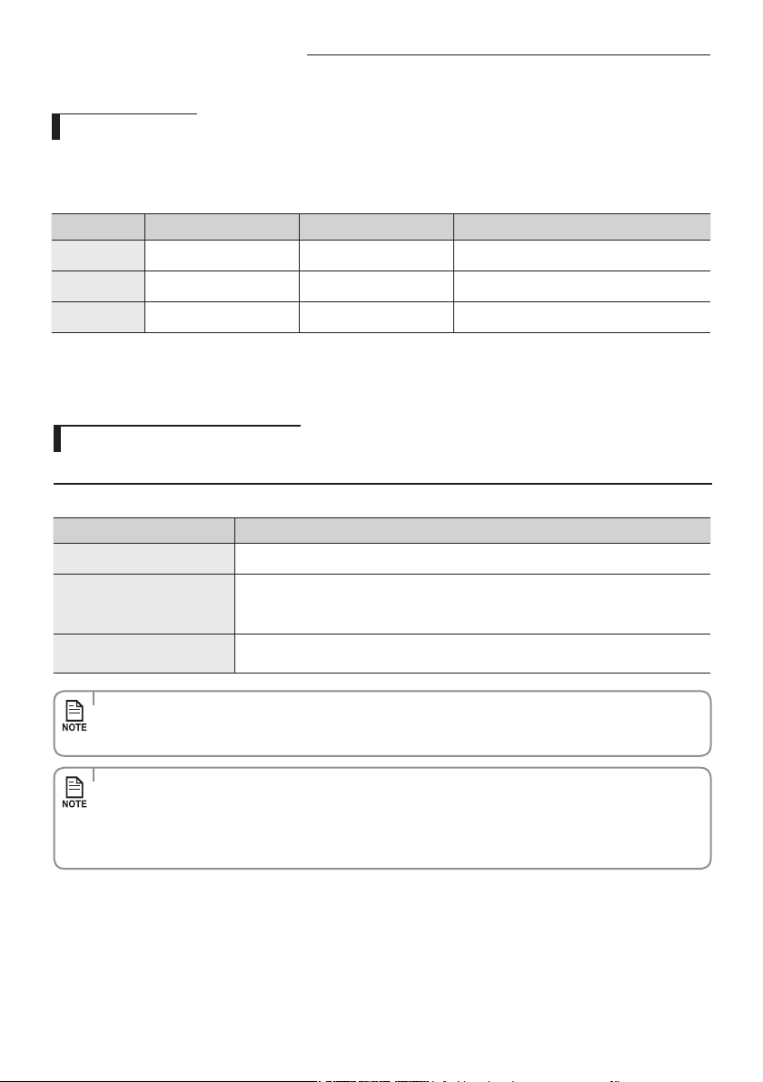
Operation ranges
The table below indicates the temperature and humidity ranges the air
conditioner can be operated within. Refer to the table for ecient use.
Maintaining your air conditioner
If the air conditioner operates in cooling mode for long period of time in high humidity area, dew may be formed.
If the outdoor temperature goes down to -5 °C, heating capacity may decrease as much as 60 %~70 % of specied capacity
according to the using conditions.
Mode Indoor temperature Outdoor temperature Indoor humidity
Cooling
16 ˚C~32 ˚C -10 ˚C~46 ˚C Relative humidity 80% or less
Heating
27 ˚C or less -15 ˚C~24 ˚C -
Dry
18 ˚C~32 ˚C -10 ˚C~46 ˚C -
Internal protections via the unit control system
This internal protection operates if an internal fault occurs in the air conditioner.
Type Description
Against cold air
The internal fan will be o to prevent cold air when the heat pump is heating.
Defrost cycle
The internal fan will be o to defrost ice when the heat pump is heating.
Vertical air ow blade will be closed during defrost cycle and it will open again during
heating operation after defrost cycle.
Protect compressor
The air conditioner does not start operating immediately to help protect the compressor
of the outdoor unit after it has been started.
• IftheheatpumpisoperatinginHeatmode,defrostcycleisactuatedtohelpremovefrostfromanoutdoorunitthat
may have deposited at low temperatures.
The internal fan is switched o automatically and restarted only after the defrost cycle is completed.
• ASamsung-brandedairconditioningunitinstalledinanareawhichisnoteasilyaccessible(includingwithout
limitation roofs or positions above 2.4 metres for the outdoor unit) may require additional costs for labour and
access equipment as may be mandated by occupational health and safety requirements. Such costs are to be
bornebyyoushouldserviceormaintenance(includingserviceormaintenancecoveredbyyourwarrantyorby
a consumer guarantee) be required.
English-11
BASIC FUNCTION02
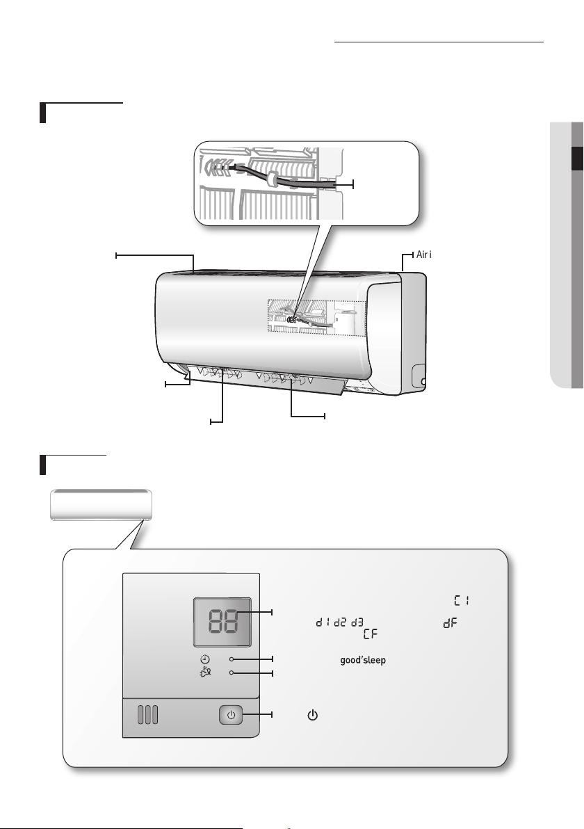
Main parts
Your air conditioner may slightly look dierent from illustration shown below depending on your model.
Checking the name of the parts
Display
Basic function
Airowblade
(leftandright)
Airowblade
(upanddown)
Airintake
Room
temperature
sensor
Blade pin lever
Airlter
(underthepanel)
Temperatureindicator/Autocleanindicator( )
/DRED(DemandResponseEnablingDevices)
indicator( , , )/Defrostindicator( )
/FilterResetindicator( )
/Power consumption indicator
Timer indicator/ indicator
Smart Saver indicator
Power button /
Remote controller receiver
English-12
Checking the remote controller
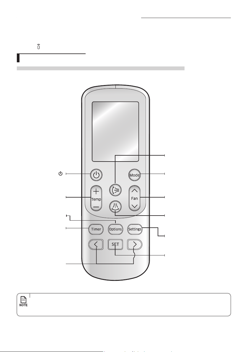
Remote controller buttons
Beforeusingthefunctionsoftheremotecontroller,youshouldsetthecurrenttime.(Refertopage17)
Power
Turn on/o the air
conditioner
Temp + –
Increase/Decrease the
temperature by 1 ˚C.
Options
Select options during operation
Timer
Select Timer option
Directional < >
Move through the Timer,
Options or Settings menu to
make a selection
Vertical air swing
Activate/Deactivateverticalairow
blade movement automatically
Horizontal air swing
This function is not available in this
model.
Settings
Select settings
SET
Set/Cancel the selected option or
setting
Mode
Set one of the 5 operating modes
Fan
Adjustthefanspeed
•Incaseyouwishtocanceltheoptionsorsettingsthatyouhavejustset,presstheOptions or Settings button again,
then the most recently selected item will blink and you may simply cancel it by pressing the SET button while
selected item is blinking.
• Pointtheremotecontrollertowardstheremotecontrollerreceiveroftheindoorunit.
• Whenyouproperlypressthebuttonontheremotecontroller,youwillhearbeepsoundfromtheindoorunitandatransmit
indicator( ) appears on the remote controller display.
English-13
BASIC FUNCTION02
• Thesignalmaynotbereceivedwellofelectroniclightingstyleuorescentlampssuchasinverteruorescent
lamps are in the same space.
• Ifotherelectricalproductsoperatebytheremotecontroller,callyournearestcontactcenter.
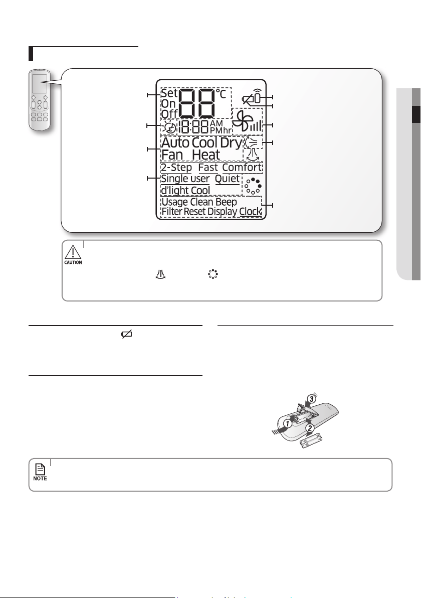
Remote controller display
Low Battery warning
Whenthebatteryisexhausted,( ) will be displayed in the
remotecontrollerdisplay.Whentheiconappears,change
thebatteries.Theremotecontrollerrequirestwo1.5VAAA
type batteries.
Storing the remote controller
Whenyoudonotusetheremotecontrollerforlongtime,
remove the batteries from the remote controller and store it.
Inserting the batteries
1. Push the lever as arrow indicates on the rear side of the
remote controller and pull up.
2. Insert two AAA batteries.
Check and match the “+” and “-” signs accordingly. Make sure
you have inserted the batteries in correct position.
3. Close the cover by place it back to its original position.
You should hear click sound when the cover is locked properly.
Operation mode indicator
Set temperature/ Time (for
Timer option) indicator
good'sleep indicator
Options indicator
Transmit indicator
Low battery indicator
Fan speed indicator
Vertical air swing indicator
Settings indicator
• Makesurethatthewaterdoesnotgettotheremotecontroller.
• Thefollowingfunctionaredisplayedontheremotecontrollerdisplaybutnotsupportedinthis
model.
- Horizontalairswing( )/ VirusDoctor( )
• Whenturningoandturningontheremotecontroller,theTimer, Options and Settings set before
turning o the remote controller are cancelled. However, the fan direction does not change.
English-14
Basic function
Basic operation is an operation mode that can be selected by pressing the Mode button.
Auto(2-Step Cooling or Heat)
In Auto mode, the air conditioner will automatically set the temperature and fan speed depending on the room
temperature.
• 2-Step Cooling mode sets the air conditioner to operate in Fast + Cool mode when set temperature is lower than indoor
temperature, and then the air conditioner will automatically operate in Dry mode when indoor temperature reaches set
temperature.
Cool
In Cool mode, the air conditioner will cool your room. You can adjust the temperature and the fan speed to feel cooler in hot
season.
• If current outside temperature is much higher than the selected indoor temperature, it may take time to bring the inner
temperature to the desired coolness.
• Quiet mode makes the noise quieter during the operation of the indoor unit in the Cool mode.
Dry
The air conditioner in Dry mode acts like a dehumidier by removing moisture from the indoor air.
Dry mode makes the air feel refreshing in a humid climate.
To activate the Dry mode, set temperature on the remote controller should be lower than indoor room temperature.
Fan
Fan mode can be selected to circulate your room. Fan mode will be helpful to refresh the stale air in your room.
Heat
The air conditioner heats as well as cools. Warm your room with this versatile appliance in the cold of winter.
• Fan may not operate for about 3~5 minutes at the beginning to prevent any cold blasts while the air conditioner is
warming up.
• Quiet mode makes the noise quieter during the operation of the indoor unit in the Heat mode.
• Since the air conditioner heats the room by taking heat energy from outdoor air, the heating capacity may decrease when
outdoor temperature is extremely low.
Use an additional heating appliance in combination with the air conditioner if you feel the air conditioner heats
insuciently.
English-15
BASIC FUNCTION02
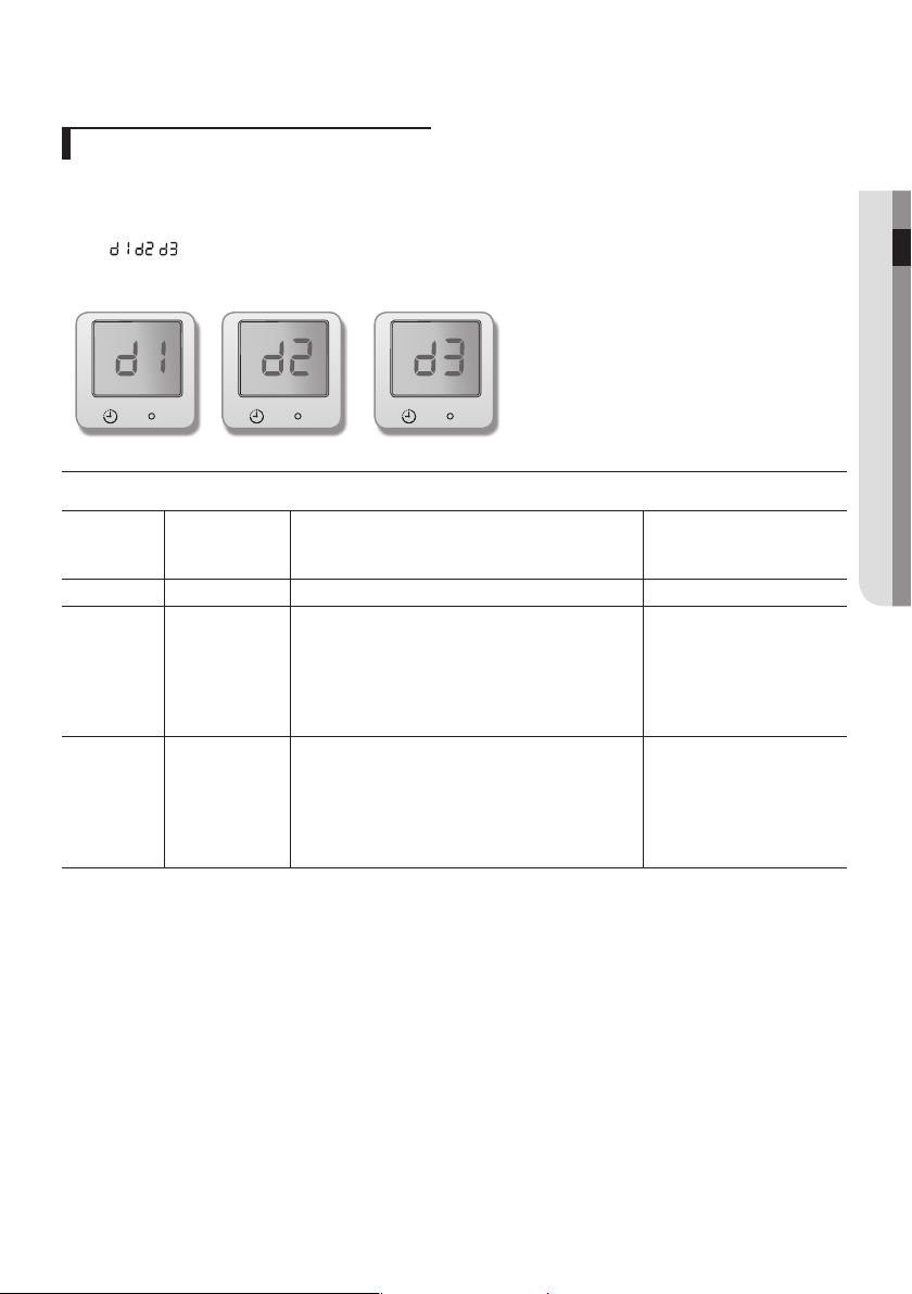
DEMAND RESPONSE MODE (DRM 1, 2, 3)
This air conditioner is equipped with a Demand Response unit which will respond to a signal sent by the power supply
utility during emergency conditions.
• During a Demand Response Event, the indoor and outdoor unit will be operated according to DRM mode (DRM 1, 2, 3) and indoor unit will
show "
, ,
" on the display.
• In case customer has set swing mode prior to DRM 1, 2, 3 being initiated, Air ow blades will continue to swing.
AIRCONDITIONERDEMANDRESPONSEMODES
Operational
instruction
(OI)
Demand
response mode
(DRM)*
Description of operation in this mode
Mandatory for compliance
withthisStandard(AS/NZS
4755.3.1)
OI 1 DRM 1 Indoor fan and Compressor o Yes
OI 2 DRM 2 The air conditioner continues to cool or heat during
the demand response event, but the electrical energy
consumed by the air conditioner in a half hour period
is not more than 50 % of the total electrical energy that
would be consumed if operating at the rated capacity
in a half hour period.
No
OI 3 DRM 3 The air conditioner continues to cool or heat during
the demand response event, but the electrical energy
consumed by the air conditioner in a half hour period
is not more than 75 % of the total electrical energy that
would be consumed if operating at the rated capacity
in a half hour period.
No
English-16
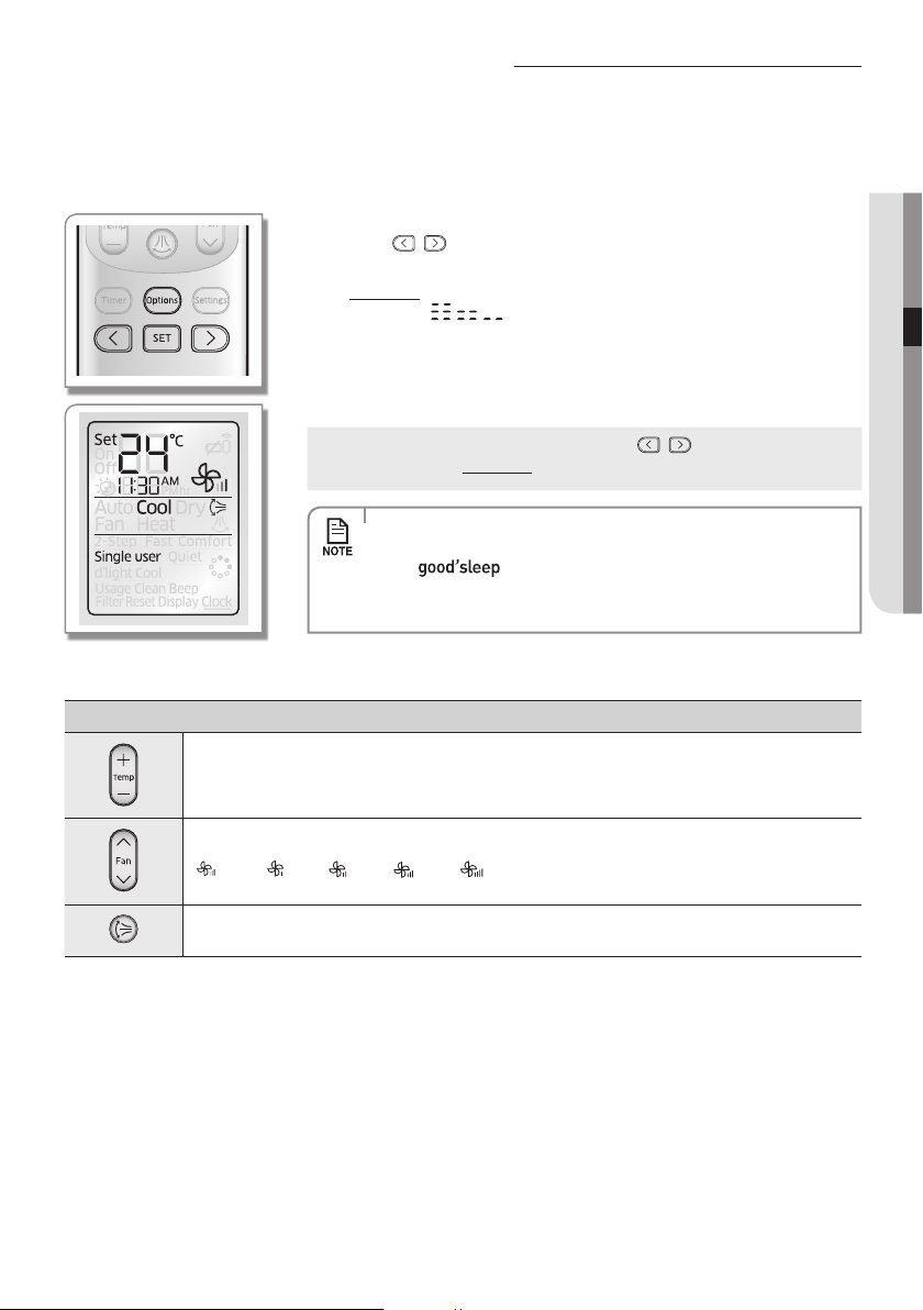
Basic function
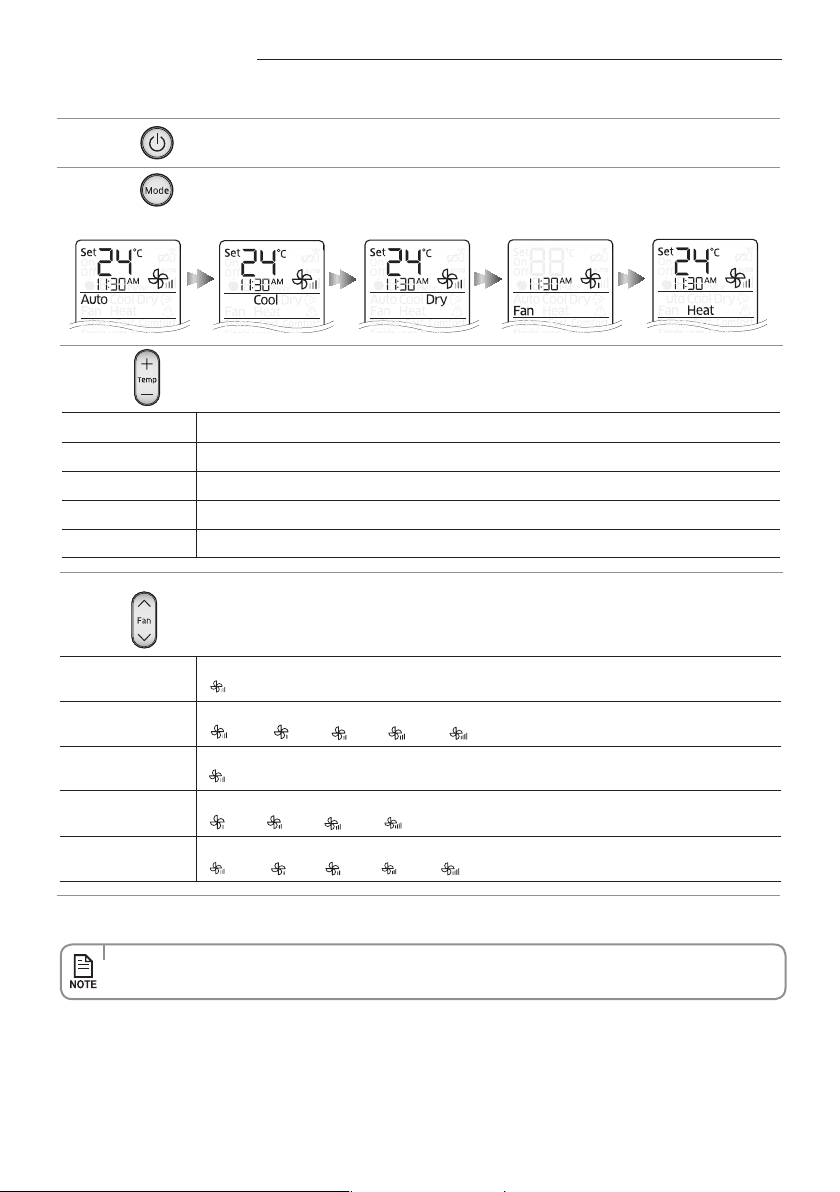
Press the button to turn on the air conditioner.
Press the button to set the operating mode.
• EachtimeyoupresstheModebutton,themodewillchangeinorderofAuto,Cool,Dry,FanandHeat.
Press the button to adjust the temperature.
Auto You can adjust the set temperature by 1 °C within the range of 16 °C~30 °C.
Cool You can adjust the set temperature by 1 °C within the range of 16 °C~30 °C.
Dry You can adjust the set temperature by 1 °C within the range of 18 °C~30 °C.
Fan Temperature adjustment is not possible.
Heat You can adjust the set temperature by 1 °C within the range of 16 °C~30 °C.
Press the button to set the desired fan speed.
Auto
(Auto)
Cool
(Auto), (Low), (Med), (High), (Turbo)
Dry
(Auto)
Fan
(Low), (Med), (High), (Turbo)
Heat
(Auto), (Low), (Med), (High), (Turbo)
• Drymodeisonlyavailableinthecoolingmode.
English-17
BASIC FUNCTION02
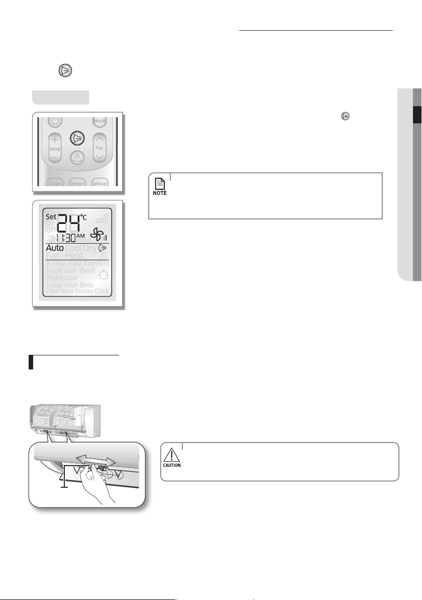
Adjusting the air ow direction
This function will allow you to adjust the air ow direction vertically.
Press the button to make air ow blades vertically.
Vertical air ow
Remote controller display
To keep the air ow direction in a constant direction, press the button
again.
The air ow blade(s) will stop the movement.
If you adjust the vertical air ow blade manually, it may not close completely
when you turn o the air conditioner.
• Adjustingtheairowdirectionisnotavailableingood'sleepmode
while it is in cool mode.
• However,youcanadjusttheairowdirectioningood'sleepmode
while it is in heat mode .
Horizontal air ow
Make sure one of the blade pin lever that stick out of the air ow blades are not broken.
Move the blade pin lever left or right to keep the air ow direction in a constant
position you prefer.
• BeextremelycarefulwithyourngerswhileadjustingtheHorizontal
air ow direction.
There is a potential risk of personal injury when the unit is mishandled.
Blade pin lever
English-18
Timer
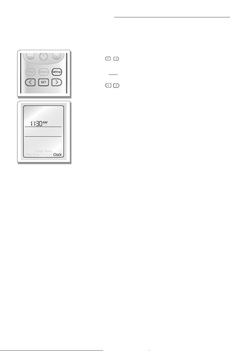
Before using the functions of the air-conditioner, set the current time.
Remote controller display
1. Press the Settings button.
2. Press the , or Settings button until (Clock) indicator starts to blink.
3. Press the SET button to set the Clock function.
- (Clock) (Clock) indicator will be displayed on the remote controller display and you
can set the time.
4. Press the button to set the time.
- You can set the time in hourly units from 1 hour ~ 12 hours according to AM, PM
and in minute units from 0 ~ 59 minutes.
5. Press the SET button to complete the current time setting.
- Current time setting will be cancelled if you don't press the SET button within
10seconds after setting the time. Therefore, check for the current time on the
remote controller display.
Setting the Current time
English-19
TIMER03
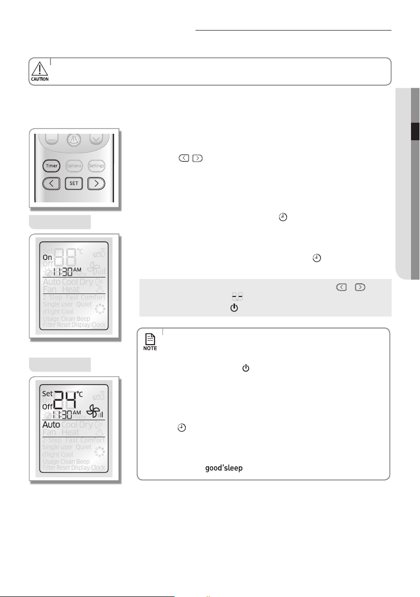
Setting the On/O timer
You can set the air conditioner to turn on/o automatically at desired time.
Setting On timer while the air conditioner is o / O timer while the air conditioner is on
Setting On timer
Remote controller display
Setting O timer
Remote controller display
1. Press the Timer button to select (On/O).
- (On/O) indicator will keep blinking and you can set the time.
2. Press the button to set the time.
- You can set the time in hourly units from 1 hour ~ 12 hours according to AM, PM
and in minute units from 0 ~ 59 minutes.
3. Press the SET button to complete the On/o timer setting.
- (On/O) indicator and the set time of the timer will be displayed on the remote
controller display and the Timer indicator (
)
will be displayed on the indoor
unit display.
- On/O timer setting will be cancelled if you don't press the SET button within
10seconds after setting the time. Therefore, check for the (On/O) indicator on
the remote controller display and the Timer indicator (
)
on the indoor unit
display.
Cancel
Press the Timer button select (On/O) press the or button
set the timer to press the SET button.
Press the Power ( ) button.
•
Check the current time on the remote controller before using this function.
•
Thedefaulttimeis1AMontheremotecontroller.Thecurrenttimeisresettodefaulttimeafterchangingthebatteries.
• When On/O timer setting is completed, the set status will be displayed
for 3 seconds, and then only (On/O ) indicator will remain on the
remote controller display thereafter.
• If you press the Power button on the indoor unit after setting the
On/O timer from the remote controller, Timer indicator on the indoor
unit display will disappear and the On/O timer will be cancelled. Even
though the On/O timer is cancelled, (On/O) indicator on the remote
controller will remain displayed.
• When the On timer is set while the air conditioner is o, Timer indicator
(
) will be displayed and remain on until the On timer turns on.
• O timer may not work depending on the On/O status of the indoor unit
and the On/O status of the indicator on the remote controller display.
• Only the latest setting timer will be applied between the On Timer/O
Timer and O timer functions.
English-20
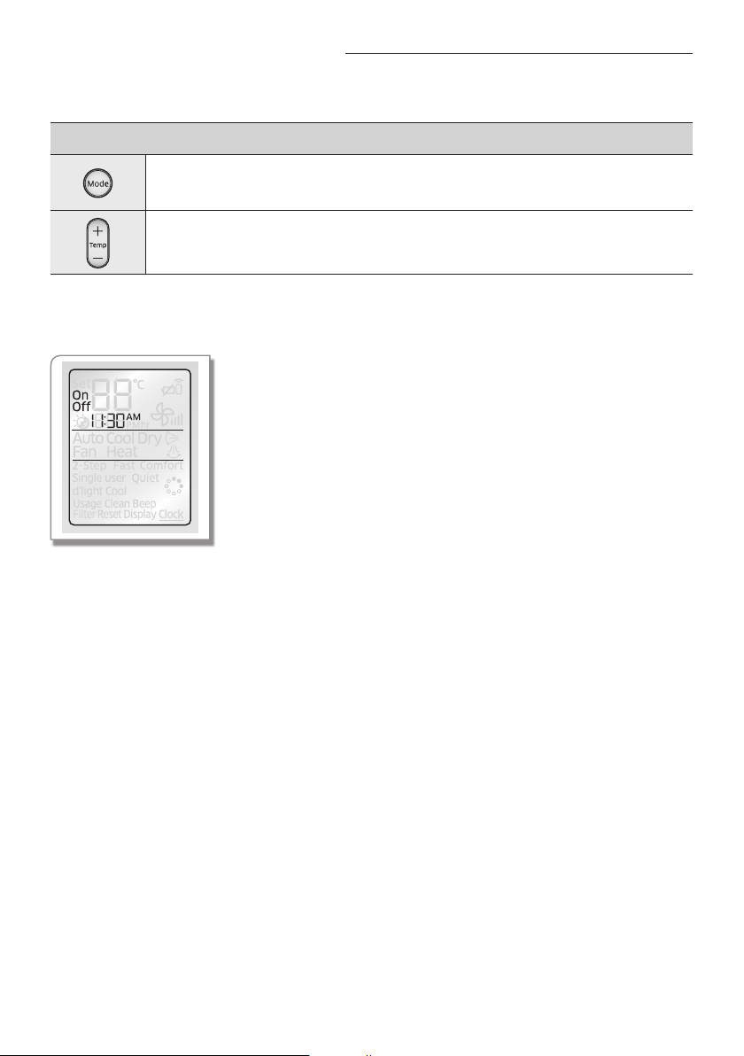
Additional options available in On/O timer mode (When the remote controller is on)
You can select from Auto/Cool/Dry/Fan /Heat.
You can set the temperature after selecting the operation mode.
Temperature adjustment is available when Auto/Cool/Dry /Heat mode is selected.
Setting on timer and o timer simultaneously
Remote controller display
Follow the same process for setting on timer and o timer.
Setting the On/O timer
English-21
TIMER03
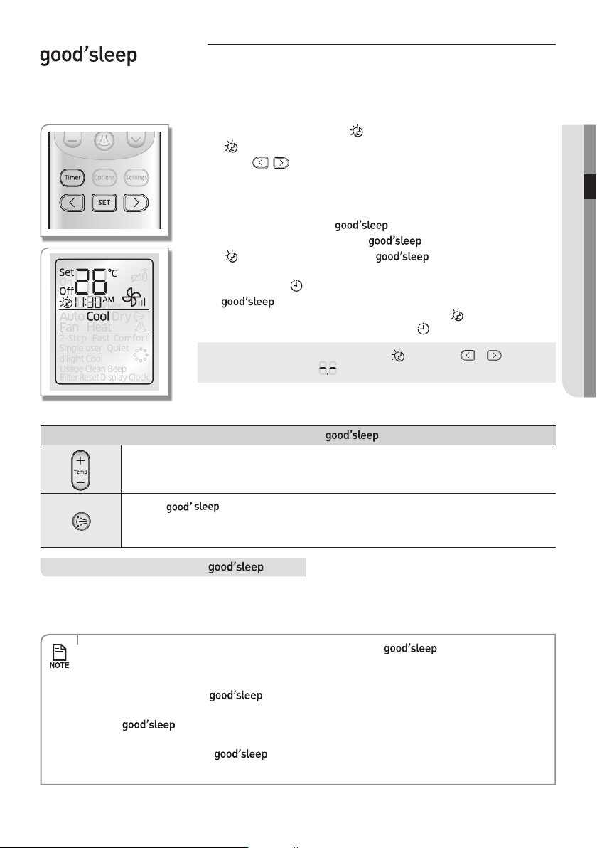
mode
For a comfortable sleep, the air conditioner will operate in 3 stages in order of Fall asleep Sound sleep Wake up stage.
When the air conditioner is operating in Cool/Heat mode;
Remote controller display
1. Press the Timer button to select ( ).
- ( ) indicator will keep blinking and you can set the time.
2. Press the button to set the time.
- You can set the time in half hour unit from 30 minutes (0.5 on the display) ~
3hours and hour unit from 3~12 hours.
- Time can be set from minimum 30 minutes to maximum 12 hours.
- Default time setting for the mode is 8 hours.
3. Press the SET button to complete the mode setting.
- ( ) indicator and the set time of the mode will be displayed on
the remote controller display.
- Timer indicator (
)
will be displayed on the indoor unit display.
- mode setting will be cancelled if you don't press the SET button within
10 seconds after setting the time. Therefore, check for the ( ) indicator on the
remote controller display and the Timer indicator ( ) on the indoor unit display.
Cancel
Press the Timer button select ( ) press the or button
set the timer to press the SET button.
Additional options available in mode
You can adjust the set temperature by 1 °C within the range of 16 °C~30 °C.
Whenthe mode is on.
InCoolmode:Airowdirectionwillbeadjustedautomatically.
InHeatmode:Adjustingairowdirectionisavailable.
Temperature and fan speed change in mode
• Fall asleep: Eases you into sleep by dropping the temperature.
• Sound sleep: Relaxes your body and raises your temperature slightly.
• Wake up: Allows you to wake up from comfortable intermittent air and it makes you feel refreshed.
• Fan speed and the air ow direction will be adjusted automatically in mode.
• Recommended set temperature is between 25
°C ~ 27 °C for cooling and 21 ˚C~23 ˚C for heating.
• If the set temperature is too low, you may feel cold during sleep or catch a cold.
• Optimal operation hour of
mode is 8 hours. Therefore, if the time is set too short or long, you
may not feel as comfortable as you would expect.
• If the
mode is set over 5 hours, Wake up stage will begin when 1 hour is remaining in the
operation time and the air conditioner will stop automatically.
• When the On timer and the
function is set simultaneously, the air conditioner will only apply
the function that was set later.
English-22
Options
Using the Fast function
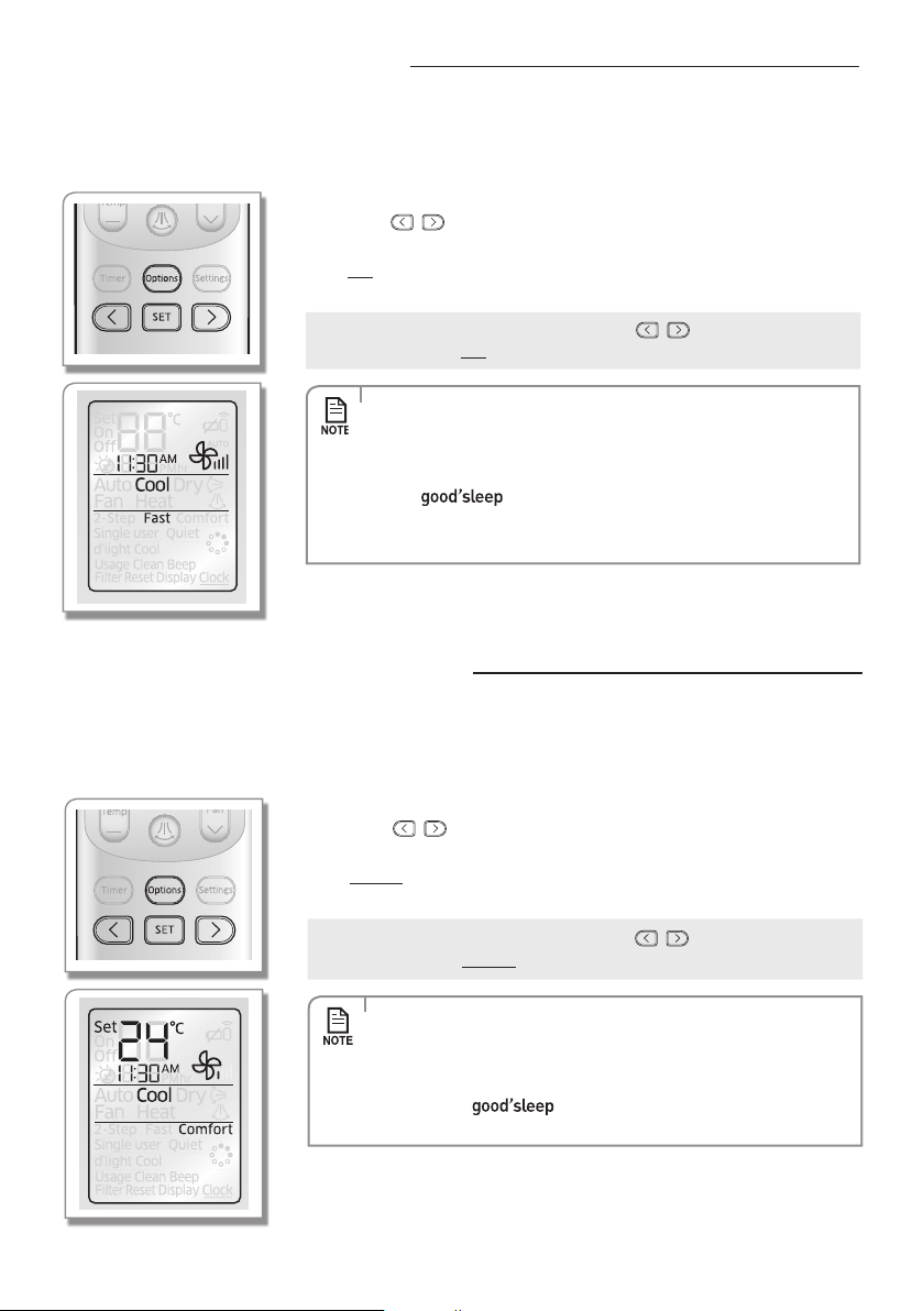
Using the Comfort function
You can set the Comfort function to provide mild cooling/heating.
When the air conditioner is operating in Cool/Heat mode;
Remote controller display
1. Press the Options button.
2. Press the , or Options button until (Comfort) indicator starts to blink.
3. Press the SET button to set the Comfort function.
- (Comfort)(Comfort) indicator will be displayed on the remote controller
display and Comfort function will begin.
Cancel
Press the Options button Press the , or Options button to
make the (Comfort) indicator blink and press the SET button.
• Comfort
function is only available in Cool/Heat mode.
• Vertical air swing can be adjusted.
• Set temperature can be adjusted, but fan speed cannot be adjusted.
• If the Comfort function is selected while
2-Step Cooling/ Fast/
Single
user/Quiet/ function is on, corresponding function will be
cancelled.
You can set the Fast function to provide fast and powerful cooling/heating.
When the air conditioner is operating in Cool/Heat mode;
Remote controller display
1. Press the Options button.
2. Press the , or Options button until (Fast) indicator starts to blink.
3. Press the SET button to set the Fast function.
- (Fast)(Fast) indicator will be displayed on the remote controller display and
Fast function will begin.
Cancel
Press the Options button Press the , or Options button to
make the (Fast) indicator blink and press the SET button.
• Fast function is only available in Cool/Heat mode.
• Vertical air swing can be adjusted.
• Set temperature and fan speed cannot be adjusted.
• If the Fast function is selected while 2-Step Cooling/Comfort/Single user/
Quiet/
function is on, corresponding function will be cancelled.
• When you select Fast function in Heat mode, you may not be able to
increase fan speed in order to prevent any cool air from blowing.
English-23
OPTIONS04
Using the Single User function
This function will reduce the energy usage while the air conditioner is operating in Cool/Heat mode.
When the air conditioner is operating in Cool/Heat mode;
Remote controller display
1. Press the Options button.
2. Press the , or Options button until (Single user) indicator starts to blink.
3. Press the SET button to set the Single user function.
- (Single user) (Single user) indicator will be displayed on the remote controller
display. Then
will be displayed on the set temperature indicator
part for few seconds and Single user function will begin.
- When the Single user function is on, vertical air swing will turn on automatically.
4.
If the current set temperature is lower than 24°C in Cool mode, it will be automatically
raised to 24 °C.
Cancel
Press the Options button Press the , or Options button to
make the (Single user) indicator blink and press the SET button.
• Single user function is only available in Cool/Heat mode.
• If the Single user function is selected while 2-Step Cooling/Fast/Comfort /
Quiet/ function is on, corresponding function will be cancelled.
• Vertical air swing will remain on even after the Single user function is
cancelled.
Additional options available in Single user function
You can adjust the set temperature by 1 °C within the range of 24 °C ~ 30 °C in Cool mode and 16 °C ~ 30 °C
in Heat mode.
(Auto), (Low), (Med), (High), (Turbo) can be selected.
Vertical air swing can be selected.
English-24
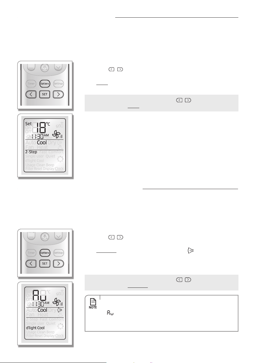
2-Step cooling function
2-Step Cooling function will set the air conditioner to cool the room quickly to reach the set temperature when the indoor
temperature is higher than the set temperature, and then the air conditioner will automatically operate in Dry mode when
indoor temperature reaches set temperature.
When the air conditioner is operating in Cool mode;
Remote controller display
1. Press the Options button.
2. Press the , or Options button until (2-Step) indicator starts to blink.
3. Press the SET button to set the 2-Step Cooling function.
- (2-Step)(2-Step) indicator will be displayed on the remote controller display
and 2-Step Cooling function will begin.
Cancel
Press the Options button Press the , or Options button to
make the (2-Step) indicator blink and press the SET button.
Using the d'light Cool function
This function will let the air conditioner select the operation mode automatically from Cool/Dry/Fan mode to provide refreshing
air.Whenthefunctionisselected,airconditionerwilloperateinCoolmodefor10minutesandchangetoappropriateoperation
mode according to surrounding environment.
Press the d'light Cool button on the remote controller while the air conditioner is operating in Cool mode;
Remote controller display
1. Press the Options button.
2. Press the , or Options button until (d'light Cool) indicator starts to blink.
3. Press the SET button to set the d'light Cool function.
- (d'light Cool)(d'light Cool) indicator and air swing ( ) indicator will be
displayed on the remote controller display and d'light Cool function will begin.
- The air conditioner will set the temperature to auto and adjust the fan speed
automatically according to the room temperature.
Cancel
Press the Options button Press the , or Options button to
make the (d'light Cool) indicator blink and press the SET button.
• d'light Cool function is only available in Cool mode.
• When d'light Cool function is activated, temperature sets automatically and
will appear on the remote controller display.
• If you press the Mode button while the d'light Cool function is on, it will
cancel the function.
English-25
OPTIONS04
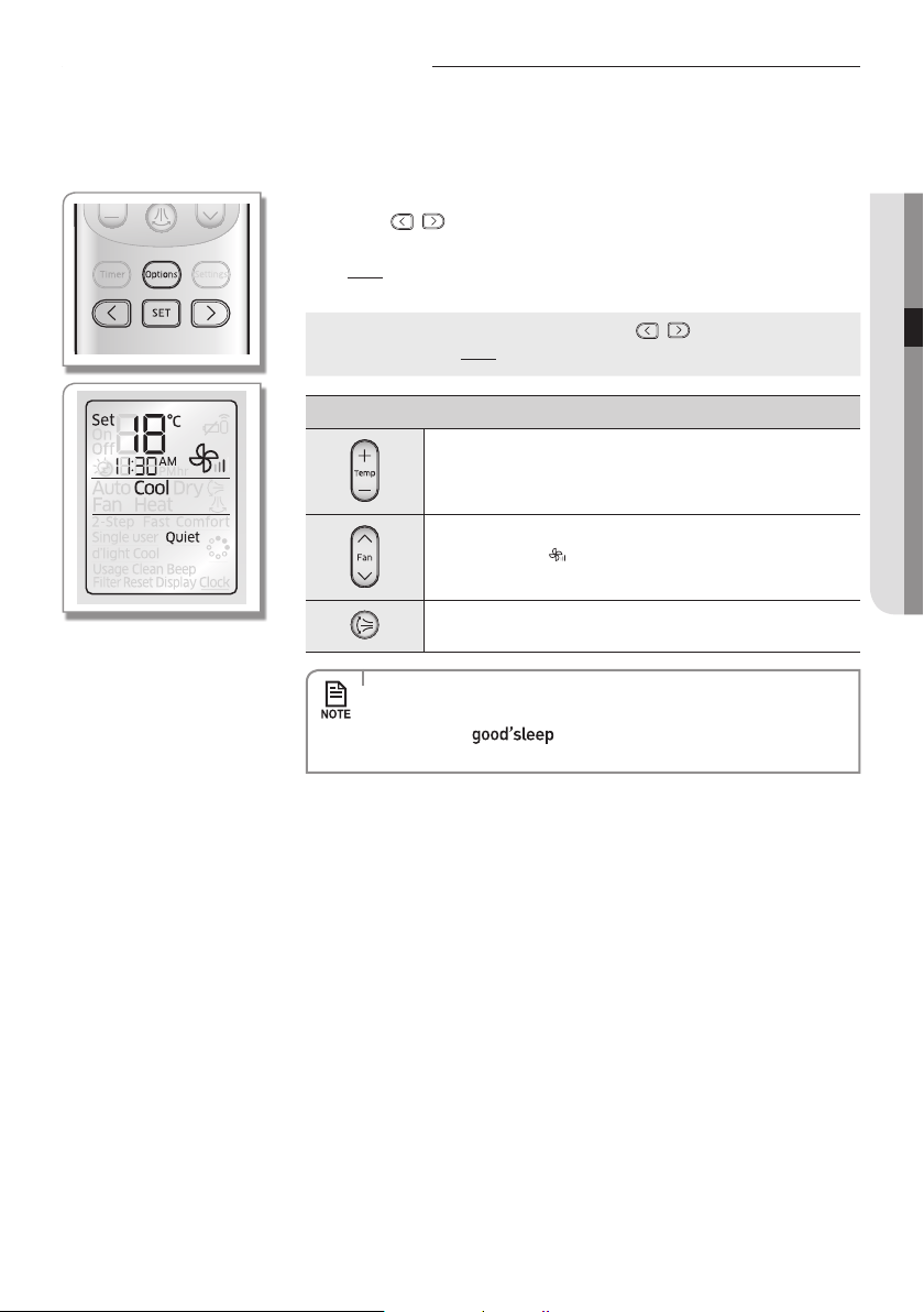
Using the Quiet function
You can reduce the noise generated from an indoor unit during Cool/Heat mode.
When the air conditioner is operating in Cool/Heat mode;
Remote controller display
1. Press the Options button.
2. Press the , or Options button until (Quiet) indicator starts to blink.
3. Press the SET button to set the Quiet function.
- (Quiet)(Quiet) indicator will be displayed on the remote controller display and
Quiet function will begin.
Cancel
Press the Options button Press the , or Options button to
make the (Quiet) indicator blink and press the SET button.
Additional options available in Quiet function
You can adjust the set temperature by 1 °C within the range of
16°C ~ 30 °C.
Fan speed is set to (Auto).
Vertical air swing can be selected.
• Quiet function is only available in Cool/Heat mode.
• If the Quiet function is selected while 2-Step Cooling/Fast /Comfort/
Single user/ function is on, corresponding function will
be cancelled.
English-26
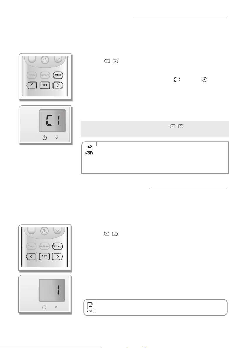
Settings
Using the Auto clean function
Auto clean function will minimise the moisture inside of the indoor unit. Activate this function to help provide you with
clean air.
When the air conditioner is operating;
Indoor unit display
1. Press the Settings button.
2. Press the , or Settings button until (Clean) indicator starts to blink.
3. Press the SET button to set the Auto clean function.
- 3 seconds after setting Auto clean function, (Clean) indicator on the remote
controller display will disappear and Auto clean ( ) and Timer ( ) indicator
will turn on the indoor unit display. Auto clean function will be activated after
the air conditioner stops operating.
- DurationoftheAutocleanfunctioncanbedierentdependingontheprevious
operation mode used.
Auto(cool),Cool,Drymode:30minutes.
Auto(heat),Heat,Fanmode:15minutes.
Cancel
Press the Settings button Press the , or Settings button to
make the (Clean) indicator blink and press the SET button.
• WhentheoperationmodeissetduringAutocleanfunctionisactivated,
theairconditionerwilloperateinchosenoperationmodeandtheAuto
clean function will be re-activated when the operation stops.
• During the auto clean function, indoor fan will continue to run and air
ow blade will remain open to expel ambient air.
Checking the power consumption
This function is displayed on the indoor unit display but not supported in 30 model.
This function will display the amount of electricity consumed by operating the air conditioner.
When the air conditioner is operating;
Indoor unit display
1. Press the Settings button.
2. Press the , or Settings button until (Usage) indicator starts to blink.
3. Press the SET button to check the power consumption.
- 3secondsaftersettingpowerconsumptioncheckingfunction,(Usage)indicator
on the remote controller will disappear.
- Indoor unit will display the amount of Power consumption for few seconds and
then return to usual status by displaying the set indoor temperature.
- Power consumption will be calculated from the moment the air conditioner is
turned on and calculated value will be reset when the air conditioner turns o.
- 1 is the default value of the electricity consumption and 99 is the maximum value.
UnitisinkWh.
• Whentheairconditionerisnotoperating,powerconsumptionwillnot
be displayed on the indoor unit display.
English-27
SETTINGS03
Setting the Beep sound
Beep sound from the indoor unit can be muted.
1. Press the Settings button.
2. Press the , or Settings button until (Beep) indicator starts to blink.
3. Press the SET button to mute the beep sound.
- 3 seconds after setting Beep soundfunction,(Beep)indicatorontheremote
controller display will disappear and Beep sound function will begin.
Setting the Display option
Display lighting can be adjusted by following this instruction.
1. Press the Settings button.
2. Press the , or Settings button until (Display) indicator starts to blink.
3. Press the SET button to set the display status.
- 3 seconds after setting Display function, (Display) indicator on the remote
controller display will disappear and indoor unit display will be turned o.
Cancel
Press the Settings button Press the , or Settings button to
make (Display) indicator blink and press the SET button.
(Display) indicator on the remote controller display will disappear and
the indoor unit display will be turned on again.
• Display option cannot be set when the air conditioner is o.
• Operation or timer display will not be turned o by the display o function.
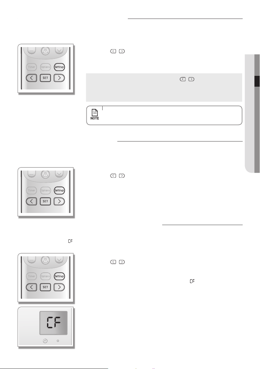
Resetting the Filter clean reminder
When Filter clean reminder ( ) lights up on the indoor unit display, clean the lter and reset the reminder by
following this
instruction.
Indoor unit display
1. Press the Settings button.
2. Press the , or Settings button until (Filter Reset) indicator starts to blink.
3. Press the SET button to reset Filter clean reminder.
- 3 seconds after setting Filter clean reminder function, (Filter Reset) indicator
on the remote controller display will disappear and ( ) indicator on the indoor
unit display will disappear.
English-28
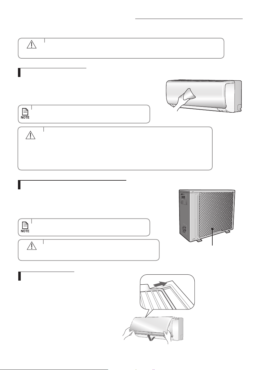
Cleaning the air conditioner
Cleaning the indoor unit
Cleaning the outdoor unit heat exchanger
Clean the product with a tepid damp cloth.
Remove the dust accumulated in the gap of the product with a soft
brush.
Whendustaccumulatesontheheatexchanger,itmaydecreasecooling
performance. Therefore, clean it regularly.
Spray water to clean the dust.
• Ifitisdiculttocleantheoutdoorunitheatexchangeron
your own, contact service center.
• Contacttheservicecenterwhenyoucleantheindoorunit
heat exchanger because it needs to be disassembled.
Heat exchanger
(Illustrationmaydierslightly
depending on the models)
• Make sure to turn o the power of the indoor unit and cut-o
the power supply before cleaning the air conditioner.
CAUTION
• Donotcleanthedisplayusingalkalinedetergent.
• Donotusesulfuricacid,hydrochloricacid,organicsolvents
(suchasthinner,keroseneandacetoneetc.)tocleanthe
surface of the product or put any stickers on it.
They may damage the surface of the air conditioner.
CAUTION
• Becarefulwiththesharpedgesonthe
outdoor unit heat exchanger.
CAUTION
Others
Opening the panel
Tightly grab bottom of grill panel and pull up.
Then slightly lift the panel up.
English-29
OTHERS06
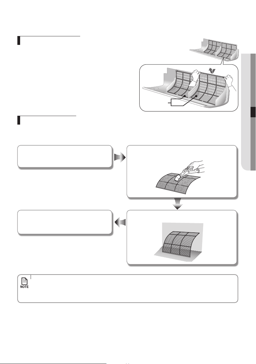
Removing the Air lter
Grabthehandleandliftitup.Then,pulltheAirltertowardsyou
and slide it down.
Airlter
Cleaning the air lter
Washablefoambasedairltercaptureslargeparticlesfromtheair.Thelteriscleanedwithavacuumorbyhandwashing.
Open the panel and put the Air filter out.
Insert the Air filter back in its original position
and close the front panel.
Dry the Air filter in a ventilated area.
Clean the Air filter with a vacuum cleaner or soft brush.
If dust is too heavy, rinse it with running water.
• CleantheAirlterevery2weeks.Cleaningtermmaydierdependingontheusageandenvironmentalconditions.
In dusty area, clean it once a week.
• IftheAirlterdriesinaconned(orhumid)area,odorsmaygenerate.Ifitoccurs,re-cleananddryitina
well-ventilated area.
English-30
Maintaining the air conditioner
If the air conditioner will not be used for an extended period of time, dry the air conditioner to maintain it in best condition.
: This check mark requires checking the indoor/outdoor unit periodically.
Follow the description to maintain the air conditioner properly.
(1)Thedescribedoperationsshouldbeperformedmorefrequentlyif
the area of installation is very dusty.
(2)Theseoperationsmustalwaysbeperformedbyqualiedpersonnel.
For more detailed information, see the installation part in the
manual.
CAUTION
1. Dry the air conditioner thoroughly by operating in Fan mode for 3 to 4 hours
and cut-o the power supply. There may be internal damage if moisture is left
in components.
2. Before using the air conditioner again, dry the inner components of the air
conditioner again by running in Fan mode for 3 to 4 hours. This helps remove
odors which may have generated from dampness.
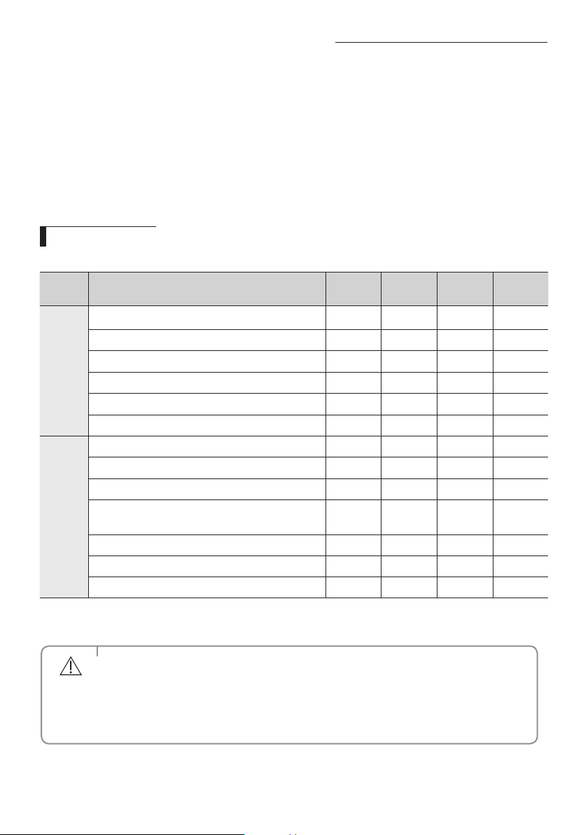
Periodical checks
Refer to the following chart to maintain the air conditioner properly.
Type Description
Every 2
weeks
Every 3
months
Every 4
months
Once a year
Indoor
unit
Clean the air lter (1)
Cleanthecondensatedrainpan(2)
Thoroughlycleantheheatexchanger(2)
Cleanthecrossfan(2)
Cleanthecondensatedrainpipe(2)
Replace the remote controller batteries (1)
Outdoor
unit
Cleantheheatexchangerontheoutsideoftheunit(2)
Cleantheheatexchangerontheinsideoftheunit(2)
Cleantheelectriccomponentswithjetsofair(2)
Verify that all the electric components are rmly
tightened(2)
Cleanthefan(2)
Verifythatallthefanassemblyisrmlytightened(2)
Cleanthecondensatedrainpan(2)
English-31
OTHERS06
Troubleshooting
Refer to the following chart if the air conditioner operates abnormally. This may save
time and unnecessary expenses.
PROBLEM SOLUTION
The air conditioner
does not work at all.
• Checkpowerstatusandthenoperatetheairconditioneragain.
• Pluginorswitchonthecircuitbreakerandthenoperatetheair
conditioner again.
• EnsureIsolatorisswitchon.
• CheckifyouhavesettheOTimer.Operatetheairconditioner
again by pressing the Power button.
The temperature
adjustment is not
working.
• CheckifyouhaveselectedFan/Fastmode.Inthesemodes,desired
temperature is set to auto and you cannot adjust the temperature.
Cool/Warm air does
not come out of the
air conditioner.
• Checkifthesettemperatureishigher(duringCoolmode)/
lower(duringHeatmode)thanthecurrenttemperature.Pressthe
Temp + or - button on the remote controller to change the set
temperature.
• CheckiftheAirlterisblockedbydirt.Ifthereisalotofduston
theAirlter,cooling(heating)performancemaydecrease.Clean
them frequently.
• Checkiftheoutdoorunitiscoveredorinstalledneartheobstacle.
Take the cover o and take the obstacle away.
• Checkiftheairconditionerisoperatingindefrostmode.Whenthe
ice formed in winter or the outdoor temperature is too low, the
air conditioner operates in defrost mode automatically. In defrost
mode, indoor fan stops and warm air does not come out.
• Ifthedoorsorwindowsareopen,itmaycausebadcooling
(heating)performance.
Close the doors and windows.
• Checkiftheairconditionerhasjustbeenturnedonafterstopping
cooling or heating operation. In this case, just a fan will run to
protect the outdoor unit compressor.
• Checkifthepipelengthistoolong.Whenthepipelengthexceeds
maximumallowablepipelength,cooling(heating)performance
may decrease.
Air ow adjustment
is not working.
• Checkifyouhaveselected mode. In this mode, you
cannotadjusttheairowdirection.(Ifthe
mode is
operating in Heat mode, you can adjust the air ow direction.)
English-32
PROBLEM SOLUTION
Fan speed
adjustment is not
working.
• CheckifyouhaveselectedAuto/Dry/Fast/ mode. In
thesemode,fanspeedissettoAutoandyoucannotadjustthe
fan speed.
Remote controller is
not working.
• Checkifyourbatteriesaredepleted.
• Makesurenothingisblockingyourremotecontrollersensor.
• Checkthattherearestronglightingapparatusneartheair
conditioner. Strong light which comes from uorescent bulbs or
neon signs may interrupt the electric waves.
Timer function does
not set.
• CheckifyoupresstheSet/Cancel button on the remote
controller after you have set the time.
The indicator
is blinking
continuously.
• PressthePower button or disconnect the power plug/switch
o the auxiliary power switch.
If the indicator is still blinking, contact the service center.
Odors permeate in
the room during
operation.
• Checkiftheapplianceisrunninginasmokyarea.Ventilatethe
room or operate the air conditioner in Fan mode for 1~2 hours.
(Wedonotusesmellycomponentsintheairconditioner.)
• ChecktheDrainshavebeenclearedRegularMaintenance.
Error is indicated. • Whenanindoorunitindicatorblinks,contactthenearestservice
center. Please ensure the error code is passed onto the service
center when booking the service call.
Noise is generated. • Dependingonthestatusoftheairconditionerusage,noisecan
be heard when refrigerant ow movement changes. It is normal.
Smoke is generated
from the outdoor
unit.
• Ifmaynotbearebutitcanbeasteamgeneratedbythedefrost
operation from outdoor heat exchanger during Heat mode in
winter.
Water is dropping
from the outdoor unit
piping connection.
• Watermaybegeneratedbecauseofthetemperaturedierence.
It is normal.
Indoor unit display
indicates “ , ,
"
• Thisisnotadefect.IftheairconditionerreceivesaDemand
Response signal from the power supply utility, then the
compressor and fans will be operated according to DRM
mode(DRM1,2,3).Theindoorunitdisplaywillindicate
" , , ".
see page 15 for more details about DRM mode.
Troubleshooting
English-33
INSTALLATION07
Carefully follow the precautions listed below because they are essential to guarantee the safety of the equipment.
•Alwaysdisconnecttheairconditionerfromthepowersupplybeforeservicingitoraccessingitsinternalcomponents.
•Verifythatinstallationandtestingoperationsareperformedbyqualifiedpersonnel.
•Verifythattheairconditionerisnotinstalledinaneasilyaccessiblearea.
General information
Carefully read the content of this manual before installing the air conditioner and store the manual in a safe place in order
to be able to use it as reference after installation.
For maximum safety, installers should always carefully read the following warnings.
Store the operation and installation manual in a safe location and remember to hand it over to the new owner if the air
conditioner is sold or transferred.
ThismanualexplainshowtoinstallanindoorunitwithasplitsystemwithtwoSAMSUNGunits.
The use of other types of units with dierent control systems may damage the units and invalidate the warranty.
The manufacturer shall not be responsible for damages arising from the use of non compliant units.
The manufacturer shall not be responsible for damage originating from unauthorized changes or the improper connection
of electric and requirements set forth in the “Operating limits” table, included in the manual, shall immediately invalidate
the warranty.
The air conditioner should be used only for the applications for which it has been designed: the indoor unit is not suitable
to be installed in areas used for laundry.
Do not use the units if damaged. If problems occur, switch the unit o and disconnect it from the power supply.
In order to help prevent electric shocks, res or injuries, always stop the unit, disable the protection switch and contact
SAMSUNG’stechnicalsupportiftheunitproducessmoke,ifthepowercableishotordamagedoriftheunitisverynoisy.
Alwaysremembertoinspecttheunit,electricconnections,refrigeranttubesandprotectionsregularly.Theseoperations
should be performed by qualied personnel only.
The unit contains moving parts, which should always be kept out of the reach of children.
Do not attempt to repair, move, alter or reinstall the unit. If performed by unauthorized personnel, these operations may
cause electric shocks or res.
Do not place containers with liquids or other objects on the unit.
Allthematerialsusedforthemanufactureandpackagingoftheairconditionerarerecyclable.
Thepackingmaterialandexhaustbatteriesoftheremotecontroller(optional)mustbedisposedofinaccordancewith
current laws.
Theairconditionercontainsarefrigerantthathastobedisposedofasspecialwaste.Attheendofitslifecycle,theair
conditioner must be disposed of in authorized centers or returned to the retailer so that it can be disposed of correctly and
safely.
Safety precautions
Installation
Installing the unit
IMPORTANT:Wheninstallingtheunit,alwaysremembertoconnectrsttherefrigeranttubes,thentheelectricallines.
Alwaysdisassembletheelectriclinesbeforetherefrigeranttubes.
Upon receipt, inspect the product to verify that it has not been damaged during transport.
Iftheproductappearsdamaged,DONOTINSTALLitandimmediatelyreportthedamagetothecarrierorretailer(ifthe
installer or the authorized technician has collected the material from the retailer.)
English-34
Aftercompletingtheinstallation,alwayscarryoutafunctionaltestandprovidetheinstructionsonhowtooperatetheair
conditioner to the user.
Do not use the air conditioner in environments with hazardous substances or close to equipment that release free ames to
avoid the occurrence of res, explosions or injuries.
To help prevent injury when accidentally touching the indoor unit fan, install the indoor unit at least 2.5m above the oor.
The air conditioner should be used only for the applications for which it has been designed : the indoor unit is not suitable
to be installed in areas used for laundry.
Our units must be installed in compliance with the spaces indicated in the installation manual to ensure either accessibility
from both sides or ability to perform routine maintenance and repairs. The units’ components must be accessible and that
can be disassembled in conditions of complete safety either for people or things.
For this reason, where it is not observed as indicated into the Installation Manual, the cost necessary to reach and repair the
unit(insafety,asrequiredbycurrentregulationsinforce)withslings,trucks,scaoldingoranyothermeansofelevation
won’t be considered in-warranty and charged to end user.
Power supply line, fuse or circuit breaker
Alwaysmakesurethatthepowersupplyiscompliantwithcurrentsafetystandards.Alwaysinstalltheairconditionerin
compliance with current local safety standards.
Alwaysverifythatasuitablegroundingconnectionisavailable.
Verify that the voltage and frequency of the power supply comply with the specications and that the installed power is
sucient to ensure the operation of any other domestic appliance connected to the same electric lines.
Alwaysverifythatthecut-oandprotectionswitchesaresuitablydimensioned.
Verify that the air conditioner is connected to the power supply in accordance with the instructions provided in the wiring
diagram included in the manual.
Alwaysverifythatelectricconnections(cableentry,sectionofleads,protections…)arecompliantwiththeelectric
specications and with the instructions provided in the wiring scheme.
Alwaysverifythatallconnectionscomplywiththestandardsapplicabletotheinstallationofairconditioners.
Indoor unit
ForWi-FiAir-conditionerinstallation,selectindoorunitlocationneartowirelessrouter.
IncaseWi-Fisignalstrengthweakened,SmartAPPmaybedisconnecteddependingontheWi-Fisignalstrength.
Whereairowisnotblocked.
Wherecoolaircanbedistributedthroughouttheroom.
Install the refrigerant piping length and the height dierence of both indoor and outdoor units as indicated in the
installation diagram.
Wallthatpreventsvibrationandisstrongenoughtoholdtheproductweight.
Out of the direct sunlight .
1mormoreawayfromtheTVorradio(topreventthescreenfrombeingdistortedornoisefrombeinggenerated).
Asfarawayaspossiblefromtheuorescentandincandescentlights(sothattheremotecontrollercanbeoperatedwell).
Aplacewheretheairltercanbereplacedeasily.
Don'tinstalldirectlyaboveelectronicsequipmentasleakingwatermaycausedamageifnotserviced.(eg.Computers,TV,etc).
Choosing the installation location
Safety precautions
English-35
INSTALLATION07
Outdoor Unit
Whereitisnotexposedtostrongwind
Wellventilatedanddustlessplaces
Wherepossiblekeepoutofsunlightandrain
Whereneighborsarenotannoyedbyoperationsoundorhotair
Solid wall or support that prevents vibration and is strong enough to hold the product weight
Wherethereisnoriskofammablegasleakage
Wheninstallingtheunitatahighplacebesuretoxtheunitlegs
3mormoreawayfromtheTVorradio(topreventthescreenfrombeingdistortedornoisefrombeinggenerated)
Install the unit horizontally
Place where drained water does not become any problem.
Placewithnoplants(especiallyclimbingplants)andwheresmallanimalcannotaccess.
Outdoor unit should not be place higher than 2.4 m or directly under eaves for accessibility for service and OH&S reasons.
• Avoidthefollowingplacestopreventmalfunctionoftheunit
-Wherethereismachineoil -Saltyenvironmentsuchasseasideareas
-Wheresuldegasexists -Otherspecialatmosphereareas
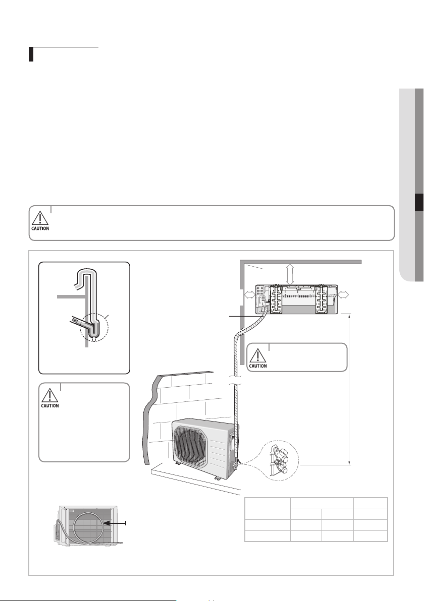
125mm
or more
100mm or more
125mm
or more
'L'metersmaximum
total pipe length
Wraptherefrigerantpipes
and the drain hose with the
absorbent pad and vinyl tape.
Refer to page 52 for further
details.
You can select the direction of
draining(leftorright).
'H'meters
maximum
total pipe
height
The appearance of the unit may be dierent from the diagram depending on the model.
Model
Pipe Length Pipe Height
Minimum Maximum Maximum
09/12
3 15 8
18/24/30
3 30 15
Make at least one round:
It will help reduce noise and vibration.
'L'masmaximumpipelength
and 3 m as minimum pipe length.
(Itwillreducenoiseandvibration)
Outdoor
Unit
Indoor
Unit
Outer wall
Cut insulation to
have rainwater
drained
MakeanU-trap(A)onthe
pipe(whichisconnected
to the indoor unit) at outer
wall and cut the bottom
partoftheinsulation(about
10mm) to prevent rainwater
from getting inside through
the insulation. However,
be careful not to damage
the pipe.
A
English-36
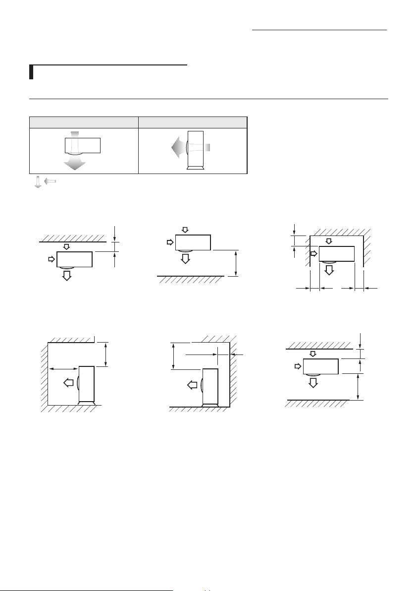
Space Requirements for Outdoor Unit
When installing 1 outdoor unit
300 or more
Whentheairoutletisoppositethe
wall
1500 or more
Whentheairoutletistowardsthe
wall
300 or more
150 or more 600 or more
When3sidesoftheoutdoorunitare
blocked by the wall
1500 or more
2000 or more
The upper part of the outdoor unit
and the air outlet is towards the wall
500 or more
300 or more
The upper part of the outdoor unit
and the air outlet is opposite the
wall
Whenthewallsareblockingfront
and the rear side of the outdoor unit
300 or
more
1500 or
more
Top view Side view
Airoutlet Airintake
Airintake
Airoutlet
Figure Description
, Airflowdirection.
(Unit:mm)
Choosing the installation location
English-37
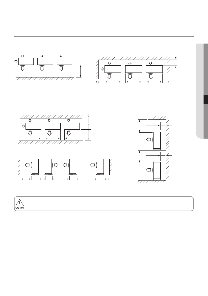
INSTALLATION07
(Unit:mm)
Whentheupperpartoftheoutdoorunitand
the air outlet is opposite the wall
Whenthewallsareblockingfrontandtherearsideoftheoutdoor
units
Whenfrontandrearsideoftheoutdoorunitistowardsthewall
500 or more
300 or more
500 or more
300 or more
300 or
more
1500 or
more
600 or more 600 or more
1500 or
more
600 or
more
3000 or
more
200 or
more
3000 or
more
• Ifinstallationisdoneininappropriatespace,unitmaygeneratesoundandcausebadeectontheproduct.
• Installationmustbedoneinlevelandinaplacewherevibrationwillnotcauseanyeect.
When installing more than 1 outdoor unit
(Unit:mm)
1500 or more
Whentheairoutletistowardsthewall When3sidesoftheoutdoorunitareblockedbythewall
300 or more
300 or more 600 or more 600 or more 600 or more
English-38
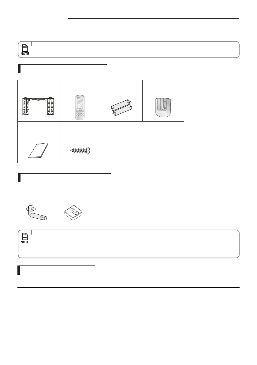
Accessories
The following accessories are supplied with the air conditioner:
• Thenumberofeachaccessoryisindicatedinparentheses.
Accessories in the indoor unit case
Accessories in the outdoor unit case
• Thearenutsareattachedtotheendofeachpipeofanevaporatororaserviceport.
Use the nuts when connecting the pipes.
• Thedrainplugandrubberlegareonlyincludedwhentheairconditionerissuppliedwithouttheassemblypipe
as seen in the picture below.
DrainPlug(1) RubberLeg(4)
Tools required for installation
General Tools
•VacuumPump(Backwardowingprevention) •ManifoldGauge •StudFinder
•TorqueWrench •PipeCutter •Reamer •PipeBender •SpiritLevel
•ScrewDriver •Spanner •Drill •LWrench •MeasuringTape
Tools for test operations
•Thermometer •ResistanceMeter •Electroscope
InstallationPlate(1)
Remote
controller(1)
Batteries for
Remotecontroller(2)
Remote Control
Holder(1)
User’s & Installation
Manual(1)
M4 x 16 Tapped
Screws(2)

English-39
INSTALLATION07
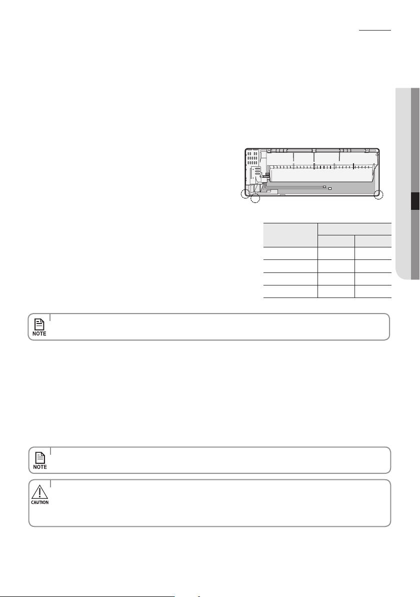
Fixing the installation plate
• Makesuretodrillonlyoneholeafterchoosingthedirectionofthepipe.
You can select the direction of the drain hose depending on where you want to install the indoor unit. Therefore before xing
the installation plate to a wall or a window frame, you must determine the position of the 65mm hole through which the cable,
pipe and hose pass to connect the indoor unit to the outdoor unit.
Whenfacingthewall,thepipeandcablecanbeconnectedfromthe:
BA
D
C
D
Direction of pipe
1. Determine the position of the pipe and drain hose hole as seen in the picture and drill the hole with an inner diameter
of 65mm so that it slants slightly downwards.
•Right(A)
•Left(B)
•Underside_right(C)
•Rear_rightorleft(D)
B
A
D
C
Pipe hole
(Ø65mm)
Wall
<20mm
Plastic
Anchor
2. Fix the indoor unit.
If you x the indoor unit on a wall
(1)Fixtheinstallationplatetothewallgivingattentiontotheweightoftheindoorunit.
If you x the indoor unit on a window frame
(1)Determinethepositionsofthewoodenuprightstobe
attached to the window frame.
(2)Attachthewoodenuprightstothewindowframegiving
attention to the weight of the indoor unit.
(3)Attachtheinstallationplatetothewoodenuprightusing
tapping screws.
If you x the indoor unit on a gypsum board
(1)Usestudndertondoutlocationsofthestuds.
(2)Fixtheplatehangerontwostuds.
• Ifyoumounttheplatetoaconcretewallusingplasticanchors,makesurethatgaps
between the wall and the plate, created by projected anchor, is less than 20mm.
• Searchforotherspotsiftherearelessthantwostuds,orthedistancebetweenthestudsaredierentfromthe
plate hanger.
• Fixtheinstallationplatewithoutincliningtooneside.
• Makesurethatawallcanwithstandtheweightoftheproduct.Ifyouinstalltheproductinaplacewhereitisnot
strong enough to withstand the product weight, the unit could fall and cause injury.
(Unit:mm)
Model A B C D
09/12
30 96 38 30
18/24/30
38 126 70 38
• Youcaninstalltherefrigerantpipeintheleft/right/bottom,ortherearsideoftheindoorunit.
• Ifchangingthepipedirectionfromlefttoright,donotdrasticallybentitbutslowlyturnitintheopposite
direction as shown. Otherwise, the pipe may be damaged in the process.
English-40
Connecting the assembly cable
Cable specication
Model
Power cable
(Outdoor Unit)
Interconnection cable
(Indoor-Outdoor)
Type GL
09/12
18/24
30
3G, 1.5mm²,
H07RN-F(**09/12**)
3G, 2.5mm²,
H07RN-F(**18/24**)
3G, 4.0mm²,
H07RN-F(**30**)
Power Supply
3 x 1.0mm², H07RN-F
(60245IEC66)
10A(09/12)
20A(18/24)
25A(30)
F1/F2
communication
2 x 0.75mm², H05RN-F
(60245IEC57)
DREDConnectedWire -
4 x 0.75mm², H05RN-F
(60245IEC57)
(Onlyfor reference)
-
•
Connecting the cable
Electrical work
(1)Forelectricalandearthworks,complywiththe‘technicalstandardsofelectricalinstallations’andthethe‘wiring
regulations’oftheLocalwiringregulations.
(2)Tightentheterminalblockscrewto1.2~1.8N•m(12~18kgf•cm).
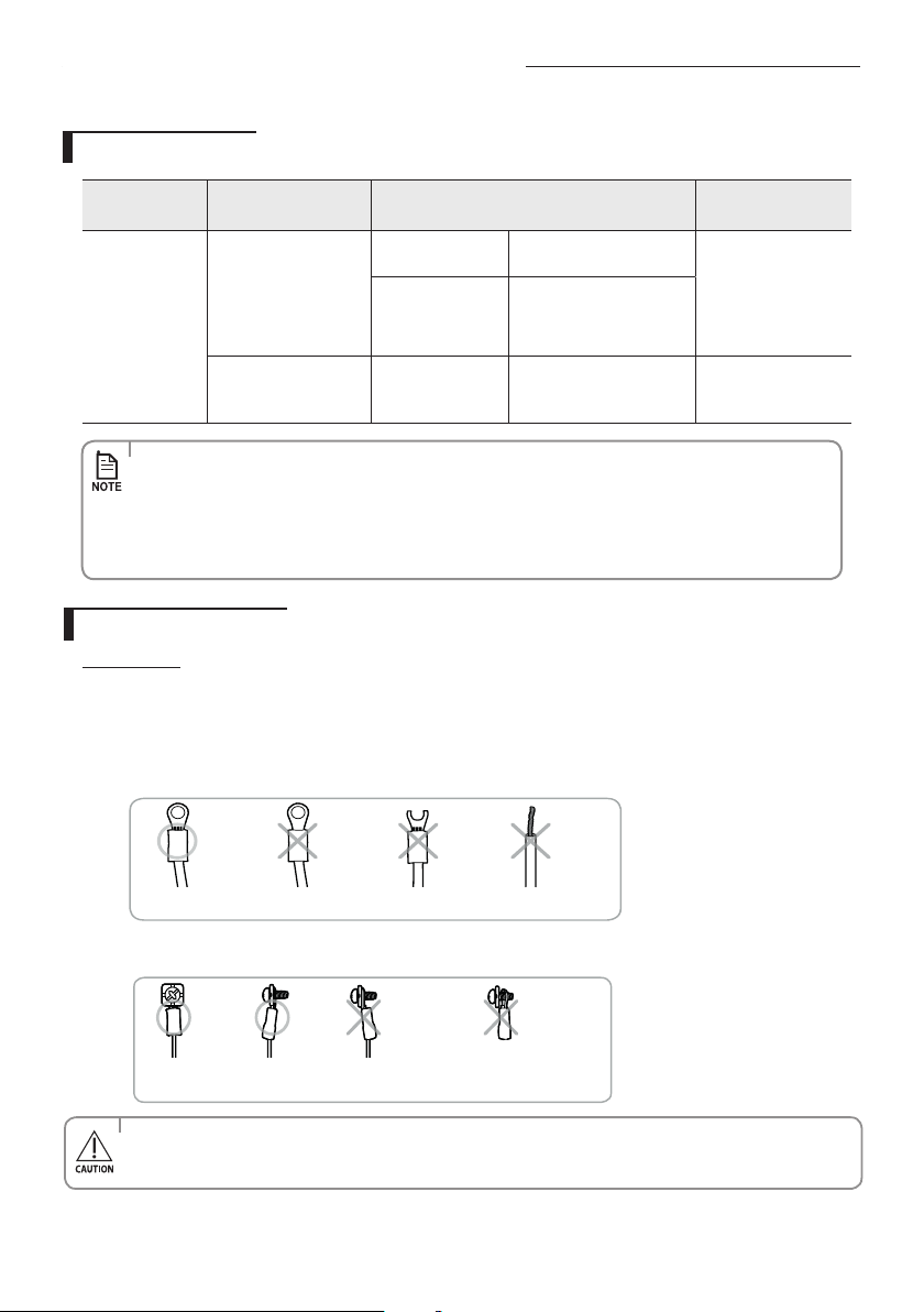
(3)Precautionswhenconnectingterminalblocksoftheindoorunit
Before connecting, make sure the connecting part of the terminal socket is facing upwards.
Upside down
The terminal
socketis damaged.
There is no ring
terminalto cover the wire.
There must be no space between the terminal and the screw when connected.
-Anyremainingspacemaybecomearehazardduetooverheatingoftheelectricalcontact.
The terminal socket
is upside down.
Either the screw is not fitted
properly or there is a space between
the screw and the ring terminal.
• Fortheterminalblockwiring,useawirewitharingterminalsocketonly.
Regular wires without a ring terminal socket may become a re hazard due to overheating of the electrical
contact during a wiring work.
• Connectthepowercabletotheauxiliarycircuitbreaker.Ifeverypolefailstoconnecttothepowersupply,
it must be incorporated in a wire with a contact opening of ≥3 mm.
• Useshieldcable(Category5;lessthan50pF/m)fornoisyenvironmentalsite.
• Powersupplycordsofpartsofappliancesforoutdooruseshallnotbelighterthanpolychloroprene
sheathed exible cord.
(CodedesignationIEC:60245IEC66/CENELEC:H07RN-F,IEC:60245IEC57/CENELEC:H05RN-F)
English-41
INSTALLATION07
2 . Open the cover panel.
3 . Remove the screw securing the connector cover.
4 . Pass the assembly cable through the rear of the indoor unit and connect the assembly cable to terminals.
(Refer to the picture below)
• Eachwireislabeledwiththecorrespondingterminalnumber.
5 . Pass the other end of the cable through the 65 mm hole in the wall.
6 . Close the connector cover by tightening the screw carefully.
7 . Close the cover panel.
8 . Remove the terminal board cover on the side of the outdoor unit.
9. Connect the cables to the terminals as seen in the picture.
• Eachwireislabeledwiththecorrespondingterminalnumber.
• DRED(DemandResponseEnablingDevice)maybesuppliedbythepowersupplyutility.
Indoor unit
Outdoor unit
• Alsocircularterminalmustbematchedwithscrewsizeinterminalblock.
• Afterconnectingthecables,makesureterminalnumbersontheindoor/outdoorunitmatches.
• PleaseensurethatPower&Communicationcablesareseparated,theymustnotbeinthesamecable.
• Power&Communicationcableshallnotexceed30m.
• Donotconnect240VdirecttoDRED’sorF1/F2terminalblocks.
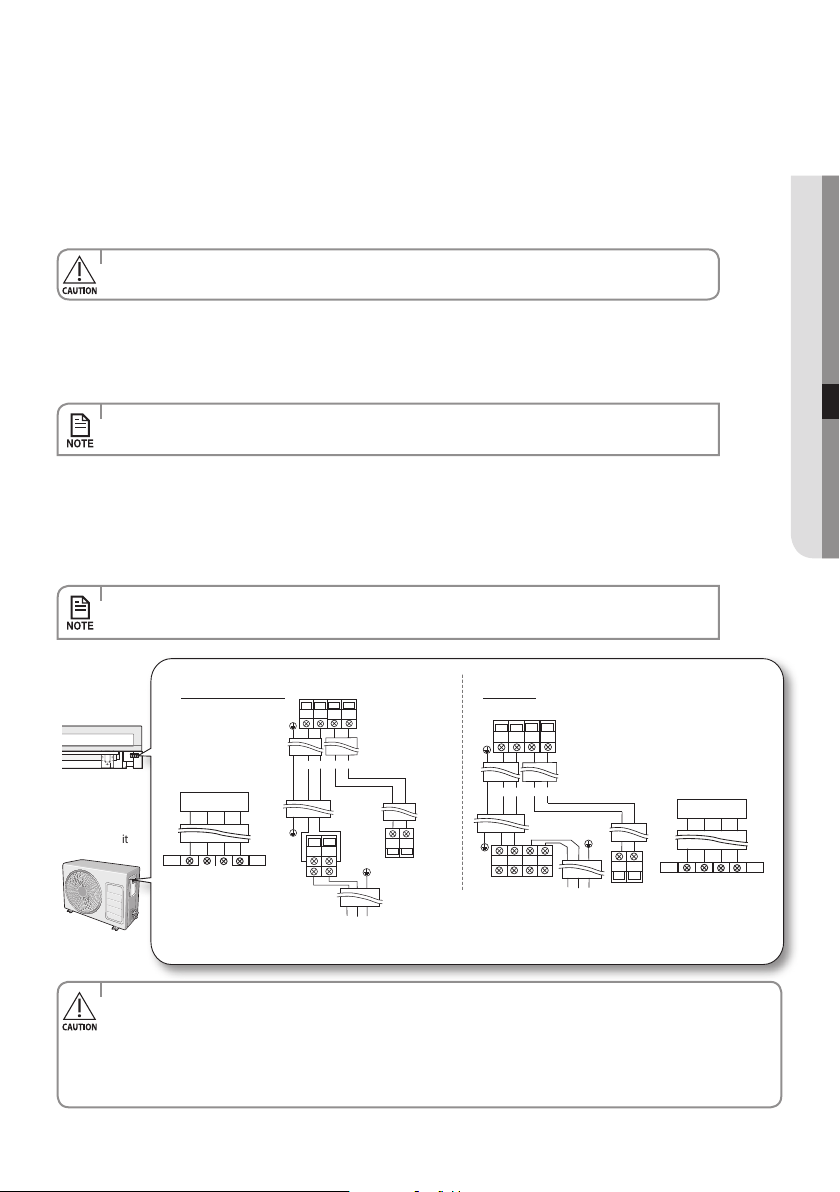
09/12/18/24 30
1. Extend the assembly cable if necessary.
• Donotconnecttwoormoredierentcablestoextendthelength.
It may cause re.
Whenyouinstalltheunit,makerstrefrigerantconnectionsandthenelectricalconnections.
Connect the air conditioner to grounding system before performing the electrical connection.
If unit is uninstalled, rst disconnect electrical cables, then refrigerant connections.
If the outdoor unit is more than 5.5 meters away from the indoor unit, you must extend the cable. The maximum length of the
cableis15(09/12)/30(18/24/30) meters.
DRED terminal block : Connection to DRED Relay or Switch.
1(L) 2(N)
F1
F2
F1
F2
1(L) 2(N)
F1
F2
L
N
DRED
DRM3
C
DRM2 DRM1
Indoor unit
Outdoor unit
1(L)
2(N)
1(L) 2(N)
F1
F2
1(L)
2(N)
F1
F2
L N
F1
F2
DRED
DRM3
C
DRM2 DRM1
Indoor unit
Outdoor unit

English-42
10. Connect the grounding conductor to the grounding terminals.
11. Close the terminal board cover by tightening the screw carefully.
• InRussiaandEurope,consultwiththesupplyauthoritytodeterminethesupplysystemimpedancebefore
installation.
• Connectthewiresrmlysothatwirescannotbepulledouteasily.
(Iftheyareloose,itcouldcauseburn-outofthewires.)
• Connectthewiresaccordingtocolorcodes,referringtothewiringdiagram.
• Thepowercableandtheinterconnectioncableshouldbeselectedaccordingtothespecicationinpage40.
DRED wiring diagram
Connecting the assembly cable
COMMON
DRM3
DRM2
DRM1
ASSY Control out
DRED SUB PBA
DRED Controller
Outdoor unit
English-43
INSTALLATION07
Installing and connecting the assembly pipe of the indoor unit
1. Cut out the appropriate knock-out piece (A, B, C) on the rear of the
indoor unit unless you connect the pipe directly from the rear.
2. Smooth the cut edges.
3. Remove the protection caps of the pipes and connect the assembly
pipe to each pipe. Tighten the nuts rst with your hands, and then with
a torque wrench, applying the following torque:
Connect indoor and outdoor units with eld-supplied copper pipes by means of are connections. Use insulated seamless
refrigerationgradepipeonly,(CuDHPtypeaccordingtoISO1337),degreasedanddeoxidized,suitableforoperatingpressures
of at least 4200 kPa and for burst pressure of at least 20700 kPa. Under no circumstances must sanitary type copper pipe be
used.
There are 2 refrigerant pipes of dierent diameters:
•Thesmalleroneisfortheliquidrefrigerant
•Thelargeroneisforthegasrefrigerant
Ashortpipeisalreadyttedtotheairconditioner.Youmay
needtoextendthepipeusingtheassemblypipe(optional).
The connection procedure for the refrigerant pipe varies
according to the exit position of the pipe when facing the wall:
•Right(A)
•Left(B)
•Underside(C)
•Rear
Outer Diameter
Torque
N•m kgf•cm
ø6.35 mm 14~18 140~180
ø9.52 mm 34~42 350~430
ø12.70 mm 49~61 500~620
ø15.88 mm 68~82 690~830
• Ifyouwanttoshortenorextendthepipes,refertopage44~45.
4. Cut o the remaining foam insulation.
5. If necessary, bend the pipe to t along the bottom of the indoor unit.
Then pull it out through the appropriate hole.
The pipe should not project from the rear of the indoor unit.
The bending radius should be 100 mm or more.
6. Pass the pipe through the hole in the wall.
7. For further details on how to connect to the outdoor unit and evacuate the air, refer to page 48~50.
• Tightenthearenutwithtorquewrenchaccordingtospeciedmethod.
If the are nut is over-tightened, the are may break and cause refrigerant gas leakage.
• DONOTWALLUPTHEPIPECONNECTION!
Allrefrigerantpipeconnectionmustbeeasyaccessibleandserviceable.
• Thepipewillbeinsulatedandxedpermanentlyintopositionafternishingtheinstallationandthegasleaktest;
refer to page 52 for further details.
B
A
C
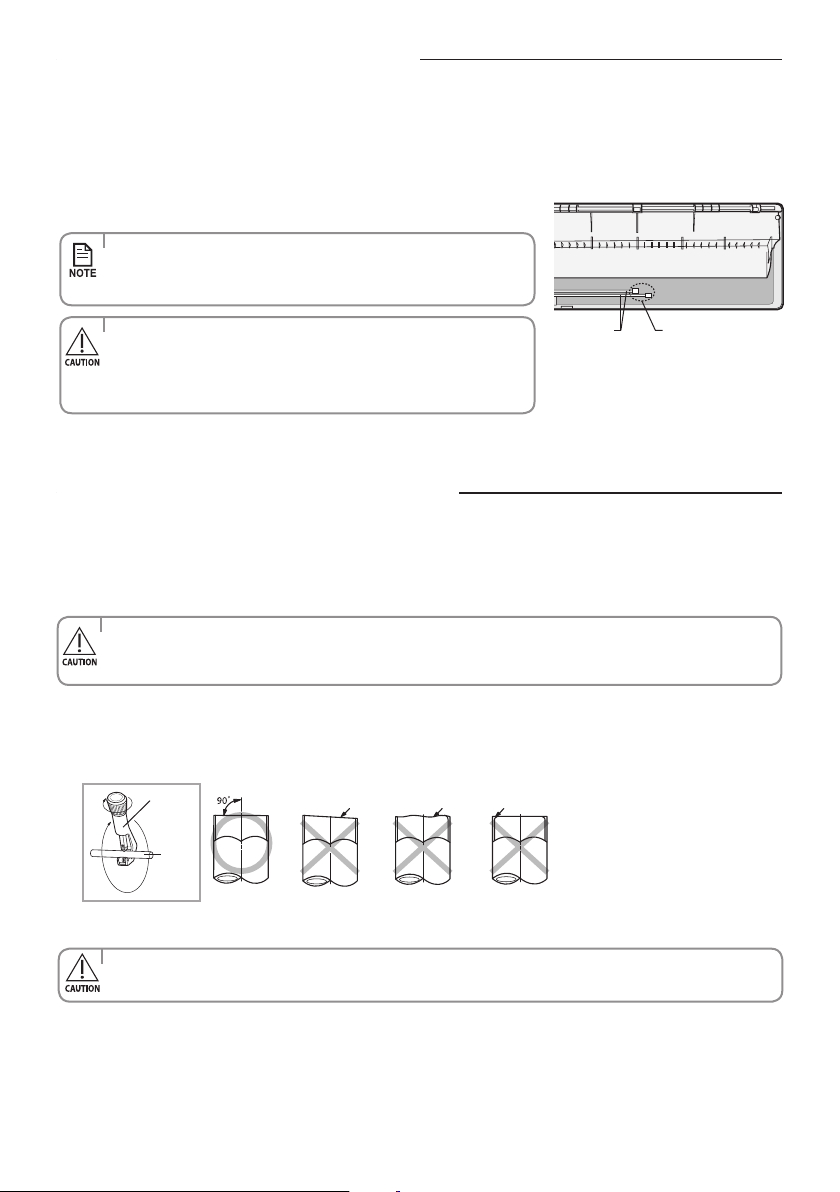
English-44
Evacuating the indoor unit
• TheremainingairintheRefrigerationcycle,whichcontainsmoisture,
may cause malfunction on the compressor.
• Alwayscontacttheservicecenteroraprofessionalinstallationagency
for product installation.
• Topreventdirtorforeignsubstancesfromgettingintothepipesduring
installation, do NOT remove the caps completely until you are ready to
connect the pipes.
The length of the pipe can be:
•Extendedupto:seetablepage35
•Shortenupto:seepage35
If you need a pipe longer than 5 meters:
• Youmustaddrefrigeranttothepipes;otherwise,theindoorunitmayfreeze.
Cutting or extending the pipe
1. Unscrew the caps at the end of each pipe.
Allinertgasexhaustsfromtheindoorunit.
Theindoorunitissuppliedwithinertgas(nitrogen).
Before installing the unit, check if nitrogen gas ow out of indoor unit.
Ifthisoneisn’ttrue,DONOTINSTALLTHEUNITsinceleakagecouldbeinsidetheindoorunit.
1. Make sure that you have all the required tools (pipe cutter, reamer, aring tool and pipe holder).
2. If you want to shorten the pipe, cut it using a pipe cutter, ensuring that the cut edge remains at 90° with the side of the
pipe (see below examples of correct and incorrect cut edges).
3. To prevent a gas leak, remove all burrs at the cut edge of the pipe using a reamer.
Oblique Rough Burr
Pipe
cutter
Pipe
• Facethepipedownwhileremovingtheburrstomakesurethatburrsdonotgetintothepipe.
Unscrew the capsPipes
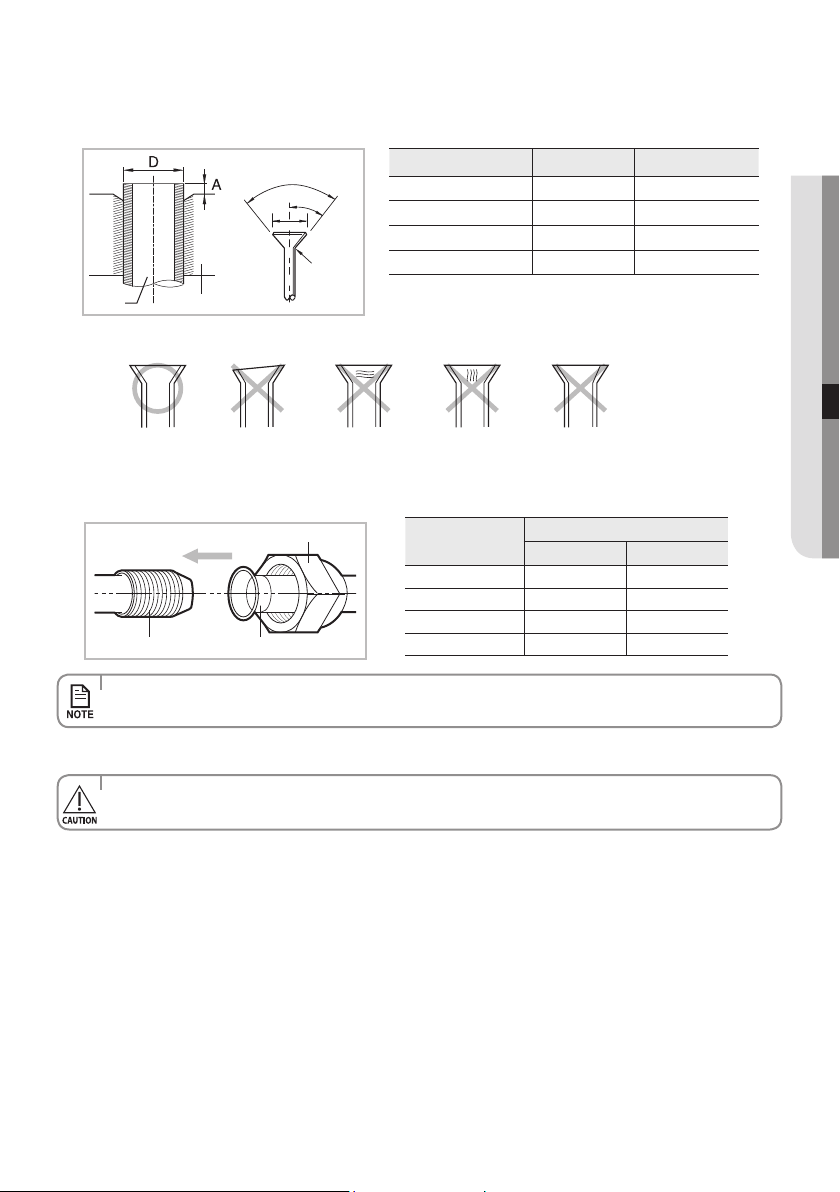
English-45
INSTALLATION07
Indoor outlet pipe Connecting pipe
Flare nut
5. Check if you ared the pipe correctly (see examples of incorrectly ared pipes below).
6. Align the pipes to connect them easily. Tighten the are nuts rst with your hands, and then with a torque wrench,
applying the following torque:
7. For further details on how to connect to the outdoor unit and evacuate the air, refer to page 48~50.
Correct
Uneven
Thickness
Cracked
Damaged
Surface
Inclined
• Excessivetorquecanbecauseofgasleakage.Ifextendingpipebywelding/brazingpleaseensurenitrogenisused
during welding/brazing process. The joint must be accessible and serviceable.
• Tightenthearenutwithtorquewrenchaccordingtospeciedmethod.
If the are nut is over-tightened, the are may break and cause refrigerant gas leakage.
4. Put a are nut slightly into the pipe and modify the are.
Outer Diameter (D) Depth (A) Flaring Size (B)
ø6.35 mm 1.3 mm 8.7 - 9.1 mm
ø9.52 mm 1.8 mm 12.8 - 13.2 mm
ø12.70 mm 2.0 mm 16.2 - 16.6 mm
ø15.88 mm 2.2 mm 19.3 - 19.7 mm
Pipe Flare
90°± 2°
°
2
±°
5
4
R 0.4~0.8
B
Outer Diameter
Torque
N•m kgf•cm
ø6.35 mm 14~18 140~180
ø9.52 mm 34~42 350~430
ø12.70 mm 49~61 500~620
ø15.88 mm 68~82 690~830
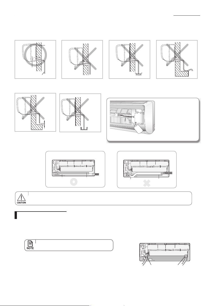
English-46
Installing and connecting the drain hose of the indoor unit
Wheninstallingthedrainhosefortheindoorunit,checkifcondensationdrainingisadequate.
Whenpassingthedrainhosethroughthe65mmholedrilledinthewall,checkthefollowings:
Drain hose installation
1. If necessary, connect the 2 meter extension drain hose to the drain hose.
2. If you use the extension drain hose, insulate the inside of the extension drain hose with a shield.
3. Fit the drain hose into 1 of 2 drain hose holes, then x the end of the drain hose tightly with a clamp.
4. WhenextendingtheDrainHose,holdtheendofDrainHoseandExtended
Hose, rotate and insert the drain hose into Extended hose for 40~45 mm.
Make sure the two hoses are rmly connected, there is no water leakage.
5. Connect the Drain Hose after using Foam Insulation to wrap the Extended Hose. Then, Use vinyl tape to wrap the
each side of connection by 20 mm .
• Ifyoudonotusetheotherdrainhosehole,
block it with a rubber stopper.
•
Don’t tie drain hose to the assembly pipe which may lead to water leakage.
• Ifthediameteroftheconnectionhoseissmallerthantheproduct'sdrainhose,waterleakagemayoccur.
Wall
Indoor unit
Drain hose
The drain hose must NOT
slant upwards.
The end of the drain hose
must NOT be placed under
water.
The drain hose must not
be bent.
Keep a clearance of at least
5cm between the end of the
drain hose and the ground.
5cm
less
Do not place the end of the
drain hose in a hollow.
Ditch
Aftercompletingthe
installation of the drain
hose, pour water into
the drain pan to check
whether the hose is well
drained.
1) Correct connection
Pipe
Drain hose
2) Incorrect connection
Pipe
Drain hose
Drain hose hole
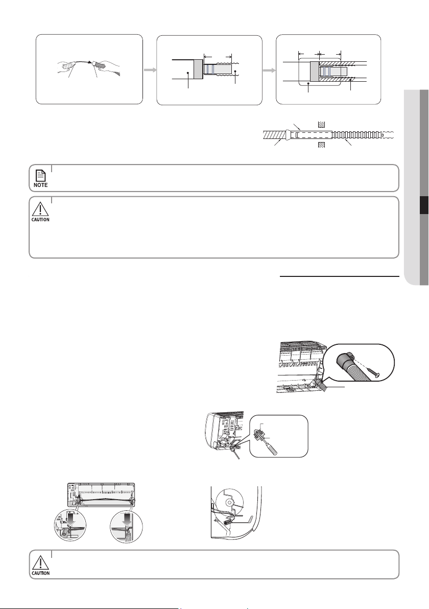
English-47
INSTALLATION07
Changing direction of the drain hose
• Thehosewillbexedpermanentlyintopositionafternishingtheinstallationandthegasleaktest;
refer to page 52 for further details.
• Makesuretheinstalleddirectionofthedrainhoseiscorrect.
Inadequate installation may cause condensate water leakage.
• Ifthedrainhoseisroutedinsidetheroom,insulatethehosesothatdrippingcondensationdoesnotdamagethe
furniture or oors.
• DONOTWALLUPTHEDRAINHOSECONNECTION!
Drain hose connection must be easy accessible and serviceable.
6. Pass the drain hose under the refrigerant pipe, keeping the drain hose tight.
7. Pass the drain hose through the hole in the wall. Check if it slants
downwards as seen in the picture.
8. Using natural drainage method, check the drainage is normal.
Shield
Drain hose Extension drain hose
Drain hose
Extension
drain hose
Drain hose
Extension
drain hose
40~45 mm
Foam Insulation
20 mm
or more
20 mm
or more
Vinyl Tape
• Makesuretheindoorunitisinuprightpositionwhenyoupourwatertocheckforleakage.
Make sure that the water does not overow onto the electrical part.
Change the direction only when it is necessary.
1. Detach the rubber cap with the plier.
2. Detach the drain hose by pulling it and turning to the right.
3. Insert the drain hose by xing it with the screw into the groove of the drain
hose and the outlet of the drain pan.
4. Attach the rubber cap with a screwdriver by turning it to the left until it xes
to the end of the groove.
5. Check for leakage on both side of the drain outlet.
Drain hose
Screw hole
Screw
Rubber cap
Drain pan outlet
Pour the water in direction of arrow.
Direction of the drained water
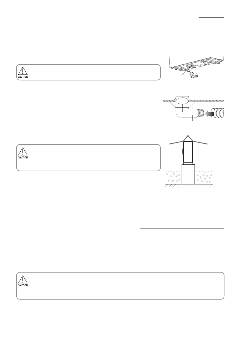
English-48
Installing and connecting the drain hose of the outdoor unit
Whileheating,icemayaccumulate.Duringtheprocessofdefrosting,checkifcondensationdrainingisadequate.Foradequate
draining, do the following.
1. Insert the drain plug into the drain hole on the underside of the outdoor unit.
2. Connect a drain hose to the drain plug.
3. Ensure that condensation draining is adequate.
Frame
Ground
Estimated
snow fall
Snow-proof hood
Bottom surface of outdoor unit
Drain hose
Drain hole
Drain plug
Drain hole
Drain plug
• Toavoiddrainplugfromcontactingtheground,securegapbetweenthe
ground and the bottom surface of the outdoor unit.
• Inareaswithheavysnowfall,piledsnowcouldblocktheairintake.
To avoid this incident, install a frame that is higher than estimated snow
fall. In addition, install a snow-proof hood to avoid snow from piling on the
outdoor unit.
TheoutdoorunitisloadedwithsucientR-410Arefrigerant.DonotventR-410Aintoatmosphere:itisauorinated
greenhousegas,coveredbyKyotoProtocol,withaGlobalWarmingPotential(GWP)=2088.
You should evacuate the air in the indoor unit and in the pipe. If air remains in the refrigerant pipes, it aects the compressor.
It may cause reduction of cooling capacity and malfunction. Use Vacuum Pump as seen in the picture.
• Wheninstalling,makesurethereisnoleakage.Whenrecoveringtherefrigerant,groundthecompressorrst
before removing the connection pipe. If the refrigerant pipe is not properly connected and the compressor works
with the service valve open, the pipe inhales the air and it makes the pressure inside of the refrigerant cycle
abnormally high. It may cause explosion and injury.
Evacuating the connected pipes
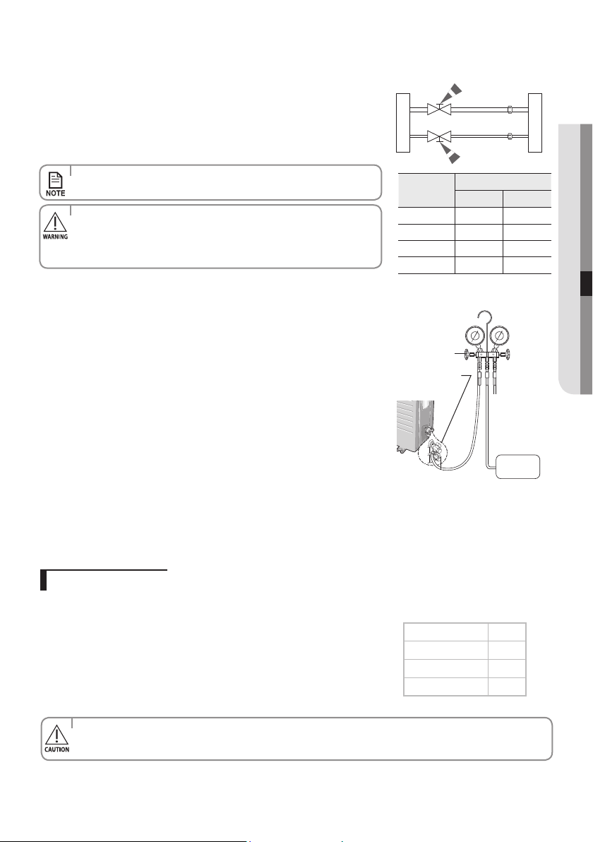
English-49
INSTALLATION07
1. Connect each assembly pipe to the appropriate valve on the outdoor unit and
tighten the are nut.
2. Tighten the are nut rst with your hands, and then with a torque wrench,
applying the following torque.
Outdoor unit Indoor unit
Gas pipe side
Liquidpipeside
• Excessivetorquecanbecauseofgasleakage.
• Maketheelectricalconnectionandleavethesysteminto“standby
mode”. Do not turn on the system!
Thisisnecessaryforbettervacuumoperation(fullOPENpositionof
Electronic Expansion Valve - EEV -).
3. Connect the charging hose of the low-pressure side of manifold gauge to a
gas service port as seen in the picture.
4. Open the valve of the low pressure side of manifold gauge counterclockwise.
5. Evacuate the air in the connected pipes using the vacuum pump for about
15 minutes.
Makesurethatpressuregaugeshows-0.1MPa(-76cmHg)afterabout
10 minutes.
This procedure is very important to avoid a gas leak.
Close the valve of the low pressure side of manifold gauge clockwise.
Turn o the vacuum pump.
Check for 2 minutes if there is any pressure change.
Remove the hose of the low pressure side of manifold gauge.
6. Set a valve cork of liquid and gas service port to the open position.
Vacuum
Pump
Manifold gauge
Valve
Gas service port
<Lowpressure>
Liquidserviceport
<Highpressure>
(Backwardflowing
prevention)
• TheremainingairintheRefrigerationcycle,whichcontainsmoisture,maycausemalfunctiononthecompressor.
• Alwayscontacttheservicecenteroraprofessionalinstallationagencyforproductinstallation.
Addrefrigerantchargeaccordingtotablebelow:
If you use a pipe longer than 5m,
‘A’gofrefrigerantR-410Amustbeaddedforeachextrameter.
If you use a pipe shorter than 5m,
The evacuating time is normal.
Refer to the Service Manual for further details.
Adding Refrigerant
Model A
09/12
15
18/24
15
30
40
Outer
Diameter
Torque
N•m kgf•cm
ø6.35 mm
14~18 140~180
ø9.52 mm
34~42 350~430
ø12.70 mm
49~61 500~620
ø15.88 mm
68~82 690~830
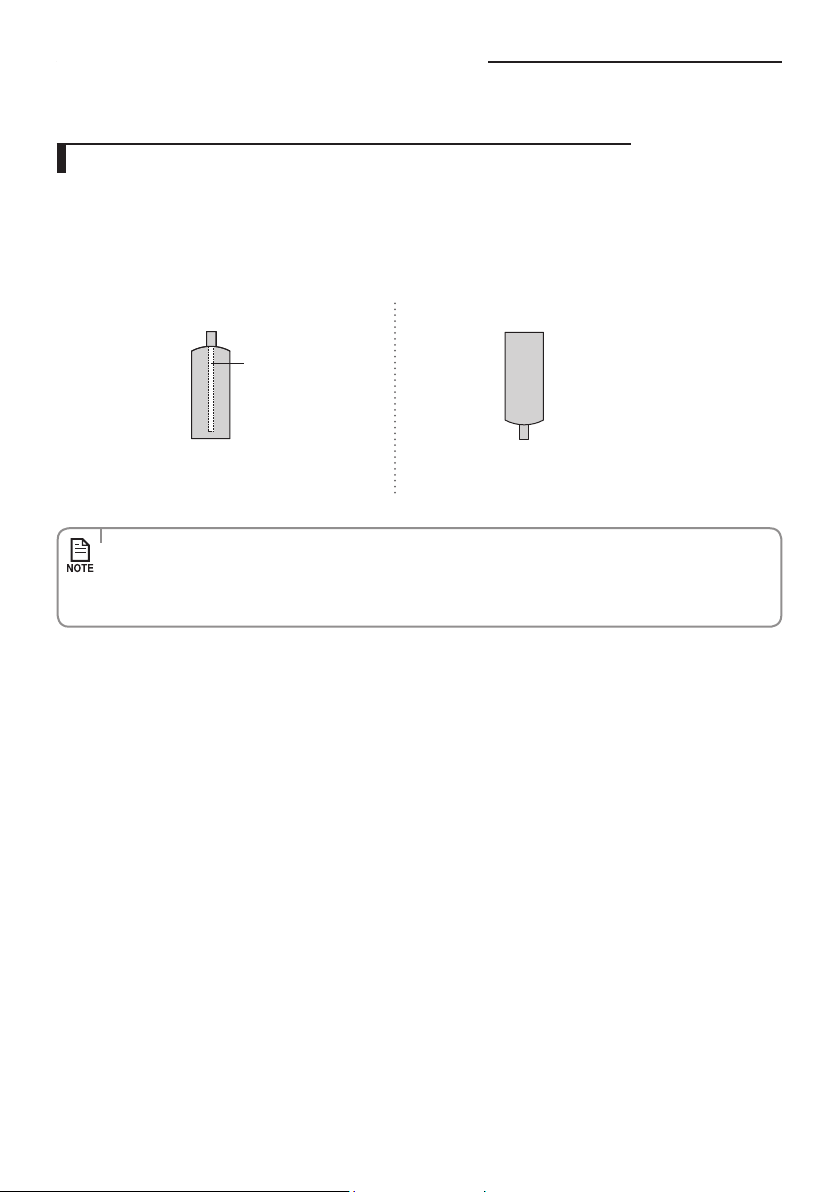
English-50
R-410Aisamixedtypeofrefrigerant.Itisnecessaryforrechargingunderconditionsofliquid.Whenrechargingrefrigerantfrom
the refrigerant cylinder to the equipment, follow the instructions below.
1. Before recharging, check whether the cylinder has a siphon or not.
There are two ways to recharge the refrigerant.
Charging the refrigerant under conditions of liquid by using a liquid pipe
Cylinder with siphon
Siphon
Charge the refrigerant standing the
cylinder upright.
Cylinder without siphon
Charge the refrigerant turning the cylinder
upside down.
• IfR-410Arefrigerantischargedwithgas,thecompositionofthechargedrefrigerantchangesandthe
characteristics of the equipment vary.
• Duringthemeasuringoperationofrefrigerantquantityaddeduseelectronicscales.
If cylinder doesn’t have syphon, upset it.
Evacuating the connected pipes
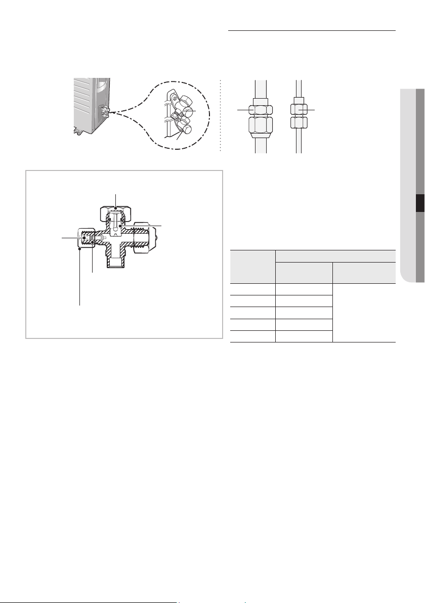
English-51
INSTALLATION07
Performing the gas leak tests
C
D
A
B
Makesuretocheckforgasleaksbeforecompletingtheinstallationprocess(connectingtheassemblypipeandhosebetween
indoor unit and outdoor unit, insulating the cables, hose and pipe, and xing the indoor unit to the installation plate).
To check for gas leaks on the outdoor unit,
CheckthevalveAandBusingaleakdetector.
To check for gas leaks on the indoor unit,
Check the are nut C and D using a leak detector.
Leak test with nitrogen (before opening valves)
Inordertodetectbasicrefrigerantleaks,beforerecreatingthevacuumandrecirculatingtheR-410A,it’sresponsibleof
installertopressurizethewholesystemwithnitrogen(usingacylinderwithpressurereducer)atapressureabove40bar
(gauge).
Leak test with R-410A (after opening valves)
Before opening valves, discharge all the nitrogen from the system and create vacuum according to page 48~50.
Afteropeningvalves,checkleaksusingaleakdetectorforrefrigerant.
Pump down (before disconnecting the refrigerant connections for unit repair, removal or disposal)
Pump-down is an operation intended to collect all the system refrigerant in the outdoor unit.
This operation must be carried out before disconnecting the refrigerant tubing in order to avoid refrigerant loss to the
atmosphere.
ShutotheliquidvalvewiththeAllenwrench.
Turn the system on in cooling with fan operating at high velocity.
(Compressorwillimmediatelystart,provided3minuteshaveelapsedsincethelaststop).
After2minutesofoperation,shutthesuctionvalvewiththesamewrench.
Turn the system o and switch mains supply o.
Disconnecttubing.Afterdisconnection,protectvalvesandtubingendsfromdust.
Compressor damage may occur if run at a negative suction pressure.
Test part for outdoor unit
Tightening torque for body cap
(Refertothetable)
Charging
core
Spindle
R-22: Diameter of the screw - 7/16-20UNF
R-410A:Diameterofthescrew-1/2-20UNF
Tightening torque for charging port cap
(Refertothetable)
Test part for indoor unit
Before inspecting the leakage, use a torque wrench
toclosethecapfortheservicevalve.(Complywitha
tightening torque for each size of the diameter,and
tighten the cap rmly to prevent any leakage.).
To check for any possible leakage, insert inert gas into
the pipes connected to indoor/outdoor units and
check the connection part of the indoor/outdoor units
with soap lather or liquid for leakage test.
Outer
Diameter
(mm)
Tightening torque
Body cap (N•m)
Charging port cap
(N•m)
ø 6.35
20 ~ 25
10 ~ 12
ø 9.52
20 ~ 25
ø12.70
25 ~ 30
ø15.88
30 ~ 35
ø19.05
35 ~ 40
(1N•m=10kgf•cm )
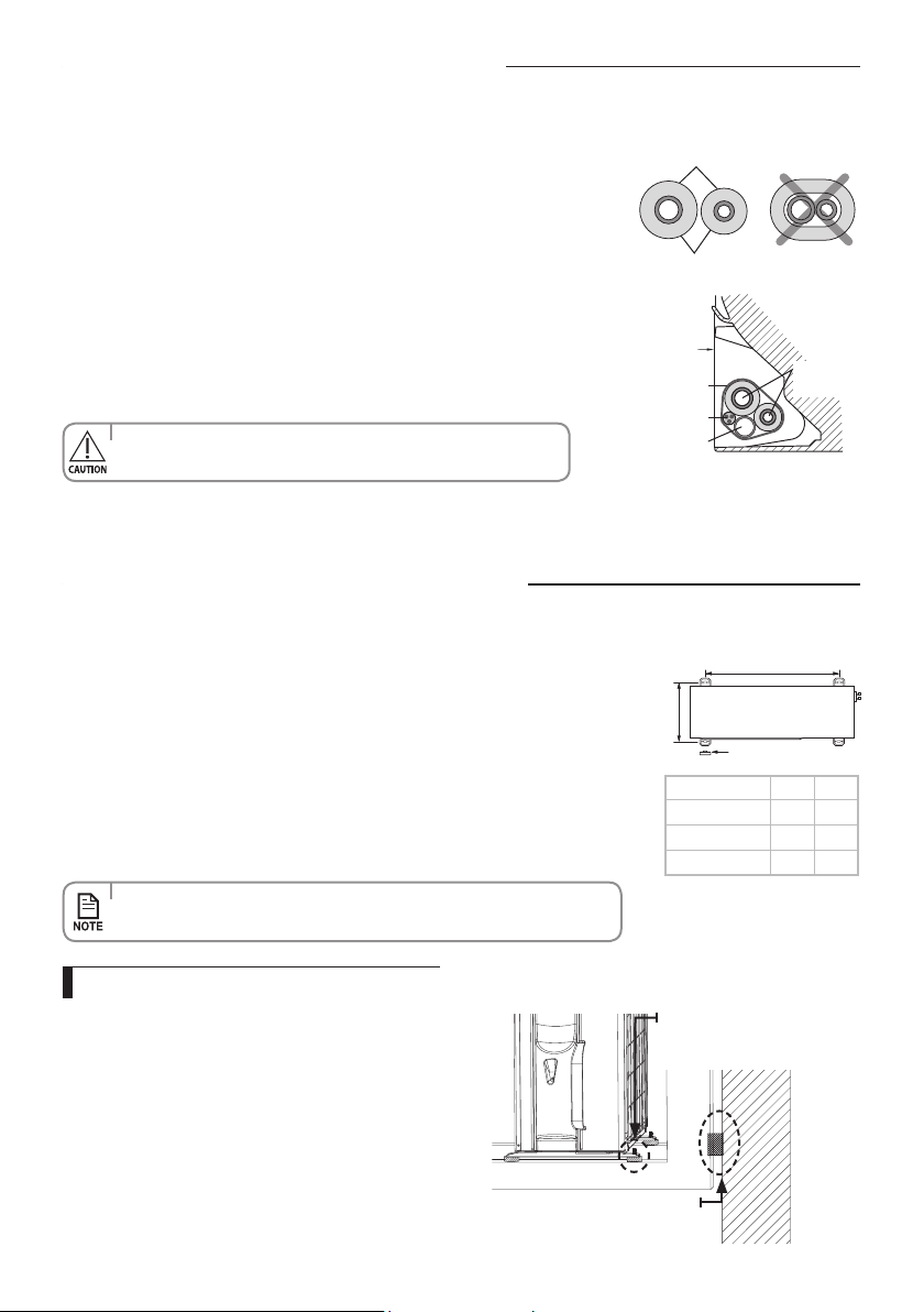
English-52
Fixing the indoor unit in place
Insulation
Pipes
'X'mm
Rubber leg
'Y'mm
Perform the following work on the area where gas leak test was done priory.
Aftercheckingforgasleaksinthesystem,insulatethepipe,hoseandcables.
Then place the indoor unit on the installation plate.
1. To minimise condensation problems, wrap foam insulation (as shown in the
gure) on a part without insulation on the end of the pipes.
2. Wind the pipe, assembly cable and drain hose with vinyl tape.
3. Place the bundle (the pipe, assembly cable and drain hose) in the lower part
of the indoor unit carefully so it does not project from the rear of the indoor
unit.
4. Hook the indoor unit to the installation plate and move the unit to the right
and left until it is securely in place.
Install the outdoor unit in level on a stable base to help avoid the generation of noise and
vibration, especially when installing the unit close to a neighbor.
If you install the outdoor unit in a place exposed to strong winds or at a height, x it to an
appropriatesupport(wallorground).
1. Place the outdoor unit as indicated on the top of the unit to let the discharged air
out properly.
2. Fix the outdoor unit in level to an appropriate support using anchor bolts.
3. If the outdoor unit is exposed to strong winds, install shield plates around the
outdoor unit so that the fan can operate correctly.
5. Wrap the rest of the pipe with vinyl tape.
6. Attach the pipe to the wall using clamps (optional).
Installation
plate
Connecting wires
Connecting
pipes
Vinyl tape
Drain hose
• Makesurepipedoesnotmovewhenyouinstalltheindooruniton
an installation plate.
Fixing the outdoor unit in place
Model X Y
09/12
602 310
18/24
660 340
30
645 340
• Ensurethewallwillbeabletosuspendtheweightofrackand
outdoorunit;
• Installtherackclosetothecolumnasmuchaspossible;
• Installpropergrommetinordertohelpreducenoiseandresidual
vibration transferred by outdoor unit towards wall.
Outdoor unit installed on the wall by rack
Soft rubber designed to cut off
vibration from rack to wall.
(notsuppliedwithproduct)
Designed to cut off residual vibration
from outdoor unit to rack.
(notsuppliedwithproduct)
• Securetherubberlegtohelppreventthegenerationofnoiseandvibration.
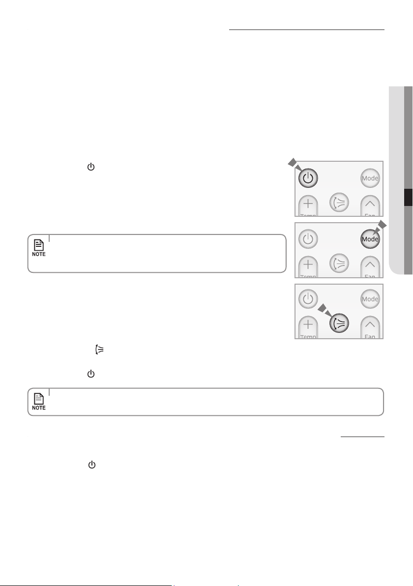
English-53
INSTALLATION07
Final check and trial operation
Pump down procedure (when removing the product)
To complete the installation, perform the following checks and tests to
ensure that the air conditioner operates correctly.
Check the followings:
•Strengthoftheinstallationsite
•Tightnessofpipeconnectiontodetectgasleak
•Electricwiringconnection
•Heat-resistantinsulationofthepipe
•Drainage
•Groundingconductorconnection
•Correctoperation(followthestepsbelow)
1. Press the Power button and check the following:
The indicator on the indoor unit lights up.
The airow blade opens and the fan gears up for operation.
3. Press the Air swing button and check the following:
The airow blades work properly.
4. Press the Power button to stop the operation.
2. Press the Mode button to select Cool or Heat mode.
In Cool mode, use Temp + or – button and set the temperature at 16°C.
In Heat mode, use Temp + or – button and set the temperature at 30°C.
Coolingmode(indoorunitcheck) Inlet air temp. - Outlet air temp:
From10°Cto12°C(indicativedeltaT)
Heatingmode(indoorunitcheck) Outlet air temp. - Inlet air temp:
From11°Cto14°C(indicativedeltaT)
In heating mode, the indoor fan motor can remain o to avoid cold air blown into
conditioned space.
• Approximately3~5minuteslater,outdoorunitwillstarttooperateandthe
CoolorWarmairwillblowout.
• After12minutesofstationaryconditionchecktheindoorunitairtreatment.
• Whenyoucompletetheinstallationsuccessfully,handoverthismanualtotheuserforstorageinahandyandsafe
place.
1. Press the Power button on the indoor unit for 5 seconds. Beep will sound immediately to let you know that the
product is ready for pump down procedure. Please let the compressor run for more than 5 minutes.
2 . Release the valve caps on High and Low pressure side.
3 . Use L wrench to close the valve on the high pressure side.
4 . After approximately 1 minutes, close the valve on the low pressure side.
5 . Stop operation of the air conditioner by pressing the power button on the indoor unit or remote controller.
6 . Disconnect the pipes.
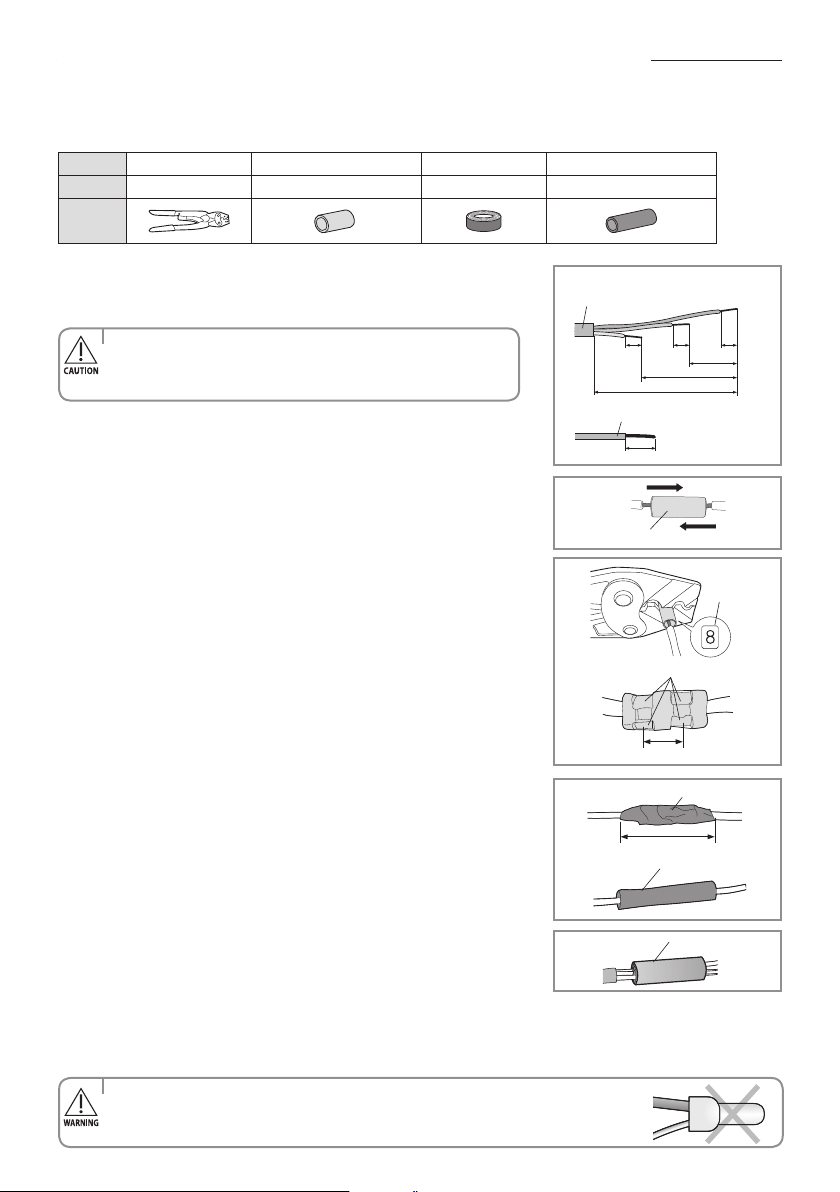
English-54
How to connect your extended power cables
Items to prepare
(compressorandinsulationtapeshouldbepreparedbyaninstallationtechnician.)
1. As shown in the gure, peel o the shields from the rubber/wire
of the power cable.
- Peel o 20 mm of the wire shields of the tube installed already.
2. Insert both sides of core wire of the power cable into the connection sleeve.
3. Using a compressor, compress the two points and ip it over
and compress another two points in the same location.
- The compression dimension should be 8.0.
- After compressing it, pull both sides of the wire to
make sure it is rmly pressed.
4. Wrap it with the insulation tape twice or more and position your contraction
tube in the middle of the insulation tape.A total of three or more layers of
insulation is required.
5. Apply heat to the contraction tube to contract it.
6. After tube contraction work is completed, wrap it with the
insulation tape to nish.
Tools Crimping pliers
Connectionsleeve(mm)
Insulation tape
Contractiontube(mm)
Spec
MH-14 20xØ7.0(HxOD) Width18mm 50xØ8.0(LxOD)
Shape
40 mm
Insulation tape
Contraction tube
(Unit:mm)
120
60
202020
180
Powercable(providedbyus)
20
Wiretubepowercable
Connection sleeve
Comp. dim.
Compress it 4 times
5 mm
Insulation tape
• Incaseofextendingtheelectricwire,pleaseDONOTusearound-shapedpressingsocket.
- Incomplete wire connections can cause electric shock or a re.
• Forinformationaboutthepowercablespecicationsforindoorand
outdoor units, refer to the installation manual.
• Afterpeelingothetubewire,youmustinsertacontractiontube.
- Make sure that the connection parts are not exposed to outside.
- Be sure to use insulation tape and a contraction tube made of approved
reinforced insulating materials that have the same level of withstand voltage
with the power cable.(Comply with the local regulations on extensions.)

English-55
INSTALLATION07
QUESTIONS OR COMMENTS?
COUNTRY CALL OR VISIT US ONLINE AT
AUSTRALIA 1300 362 603 www.samsung.com/au/support
NEW ZEALAND 0800 726 786 www.samsung.com/nz/support
AR✴✴FSSSBWK Series
AR✴✴FSSSCUR Series
Air Conditioner
user & installation manual
imagine the possibilities
Thank you for purchasing this Samsung product.
To receive more complete service, please
register your product at
www.samsung.com/register
This manual is made with 100% recycled paper.
ARKSFTSeries
Air Conditioner
user & installation manual
imagine the possibilities
Thank you for purchasing this Samsung product.
DB68-05300A-02
EN