Loading ...
Loading ...
Loading ...
14 | JL Audio - MHD750/1 Owner’s Manual
15
The amplifier will turn back on automatically
when voltage climbs back above 9 volts. This
shut-down and turn-on behavior may happen
in a rapid cycle when bass-heavy program
material causes a weak charging system to
momentarily dip too low. If this is happening
in your system, have your charging system
inspected to make sure it is working properly.
If no problem is found with the supply
voltage to the amplifier and you are
still seeing alternating Red and Green
on the “Status” LED, it is likely that the
amplifier is suffering from an internal
fault that requires factory service.
For more information on troubleshooting this
amplifier, refer to Appendix D (pages 18, 19).
SERVICING YOUR JL AUDIO AMPLIFIER
If your amplifier fails or malfunctions, please
return it to your authorized JL Audio dealer so
that it may be sent in to JL Audio for service.
There are no user serviceable parts or fuses inside
the amplifier. The unique nature of the circuitry
in the JL Audio amplifiers requires specifically
trained service personnel. Do not attempt
to service the amplifier yourself or through
unauthorized repair facilities. This will not only
void the warranty, but may result in the creation
of more problems within the amplifier.
If you have any questions about the installation or
setup of the amplifier not covered in this manual,
please contact your dealer or technical support.
JL Audio Technical Support:
(95 4) 4 4 3-110 0
9:00 AM – 5:30 PM (Eastern Time Zone)
Monday - Friday
APPENDIX A:
MHD750/1 Specifications
Amplifier Topology: Class D, switching type with
patented Single-Cycle Control™ technology.
Power Supply: Pulse width modulation-regulated
switching power supply
Recommended Fuse Value / Type: 60A (AFS, AGU or
MaxiFuse™)
Rated Power:
750W RMS x 1 @ 1.5-4Ω (11V - 14.5V)
THD at Rated Power: <0.03% @ 4Ω
(Average at 1 kHz)
Signal to Noise Ratio (20 kHz Bandwidth):
Referred to Rated Power: 111 dBA
Referred to 1 Watt: 82.2 dBA
Frequency Response: 6 Hz - 30 kHz (+0, -1dB)
Damping Factor:
>500 @ 4Ω per ch. / 50 Hz
>250 @ 2Ω per ch. / 50 Hz
Crossover Filter:
Filter Type: State-variable, 12 dB/octave Butterworth or
24 dB/octave Linkwitz-Riley
Filter Modes: Low-Pass or High-Pass, Defeatable.
Cutoff Freq. Range: Continuously variable, 50 - 500 Hz
Input Sections:
No. of Inputs: One Stereo Pair, sums to mono
Input Type: Differential-balanced with RCA jack inputs
Input Range: Switchable from 200mV - 2V RMS (Low)
to 800mV - 8V RMS (High)
Preamp Output:
2-Channel, buffered pass-through type
Chassis Dimensions (LxWxH):
10.74 in. x 7.85 in. x 1.93 in. (273 mm x 199.5 mm x 49 mm)
Dimensions do not include connectors.
Speaker loads below 1.5Ω nominal are not
recommended and may cause the amplifier
output to distort excessively.
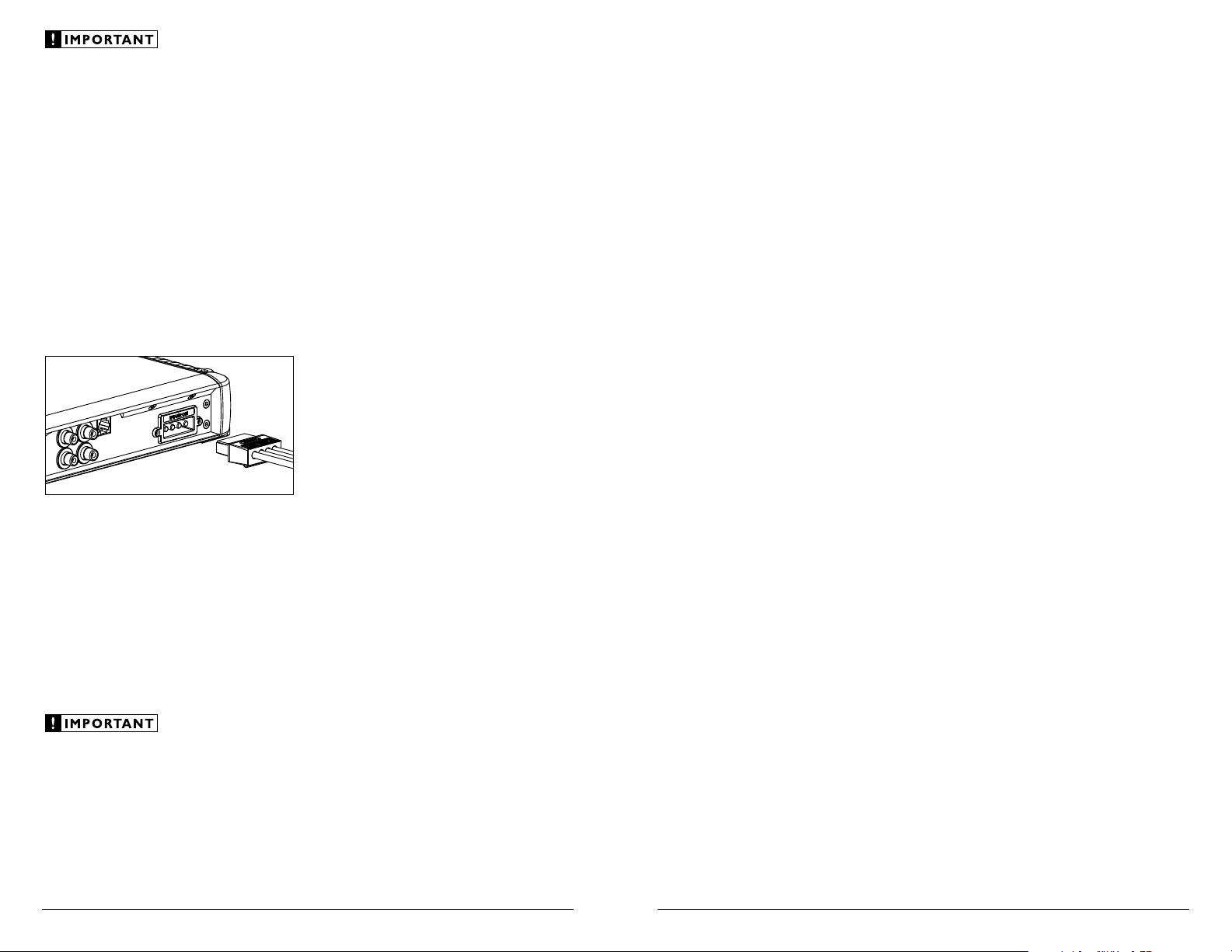
Speaker Connector Plugs
To connect the speaker wires to the amplifier,
unplug the speaker connector plug from the
amplifier chassis (pull back firmly) and back out
the set screws on the connector plug, using the
supplied 2.0 mm hex wrench. Strip 3/8 inch (10
mm) of insulation from the end of each wire and
insert the bare wire into the receptacle on the
speaker connector plug, seating it firmly so that
no bare wire is exposed. While holding each wire
in place, tighten each set screw firmly, taking care
not to strip the head of the screw.
You will notice that there are two sets of “+” and
“–” connections on the plug. This is to facilitate
multiple speaker wiring to the MHD750/1’s mono
output. The two positive and two negative
connections are connected in parallel inside the
amplifier. Connecting two speakers, each to
one set of positive and negative terminals, will
result in a parallel speaker connection. If only
connecting one pair of speaker wires, it is not
necessary to use both sets of connections.
Do not chassis ground any speakers connected
to this or any other JL Audio amplifier. Doing
so will cause the amplifier to go into protection
and mute the output.
“STATUS” LED / PROTECTION CIRCUITRY
There is a single multi-color LED on the
control panel of the amplifier to indicate the
amplifier’s operating status. This LED’s behavior
is as follows:
1) Flashing Green: amplifier is powering up,
audio output is muted.
2) Constant Green: amplifier is on and
functioning normally, audio output is active.
3) Constant Red: lights to indicate that the
amplifier has exceeded its safe operating
temperature, putting the amplifier into a
self-protection mode, which reduces the
peak power output of the amplifier. The red
light will turn green and the amplifier will
return to full-power operating mode when its
temperature returns to a safe level.
3) Constant Amber (yellow): lights to indicate
that the impedance of the speaker load
connected to the amplifier is lower than its
optimum load impedance range. When this
light is on, a protection circuit engages and
reduces the power output of the amplifier.
The amber indicator will also light when a
short-circuit is detected in the speaker wiring
(this can be a short between the positive and
negative speaker wires or between either
speaker wire and the vessel chassis).
4) Alternating Red and Green: lights to indicate
that the amplifier is experiencing a fault
that may require service of the amplifier,
its wiring or the vessel’s charging system.
Audio is muted when this fault occurs. The
most likely cause of this fault is a low supply
voltage condition. If battery voltage drops
below 8.5 volts at any point, the amplifier
(except for the “Status” LED) will shut itself
off to protect itself and the vessel’s charging
system. If the voltage drops below 6 volts,
the “Status” LED will also turn off.
Due to ongoing product development, all specifications are subject to
change without notice.
Loading ...
Loading ...
Loading ...