Loading ...
Loading ...
Loading ...
8 | JL Audio - MHD750/1 Owner’s Manual
9
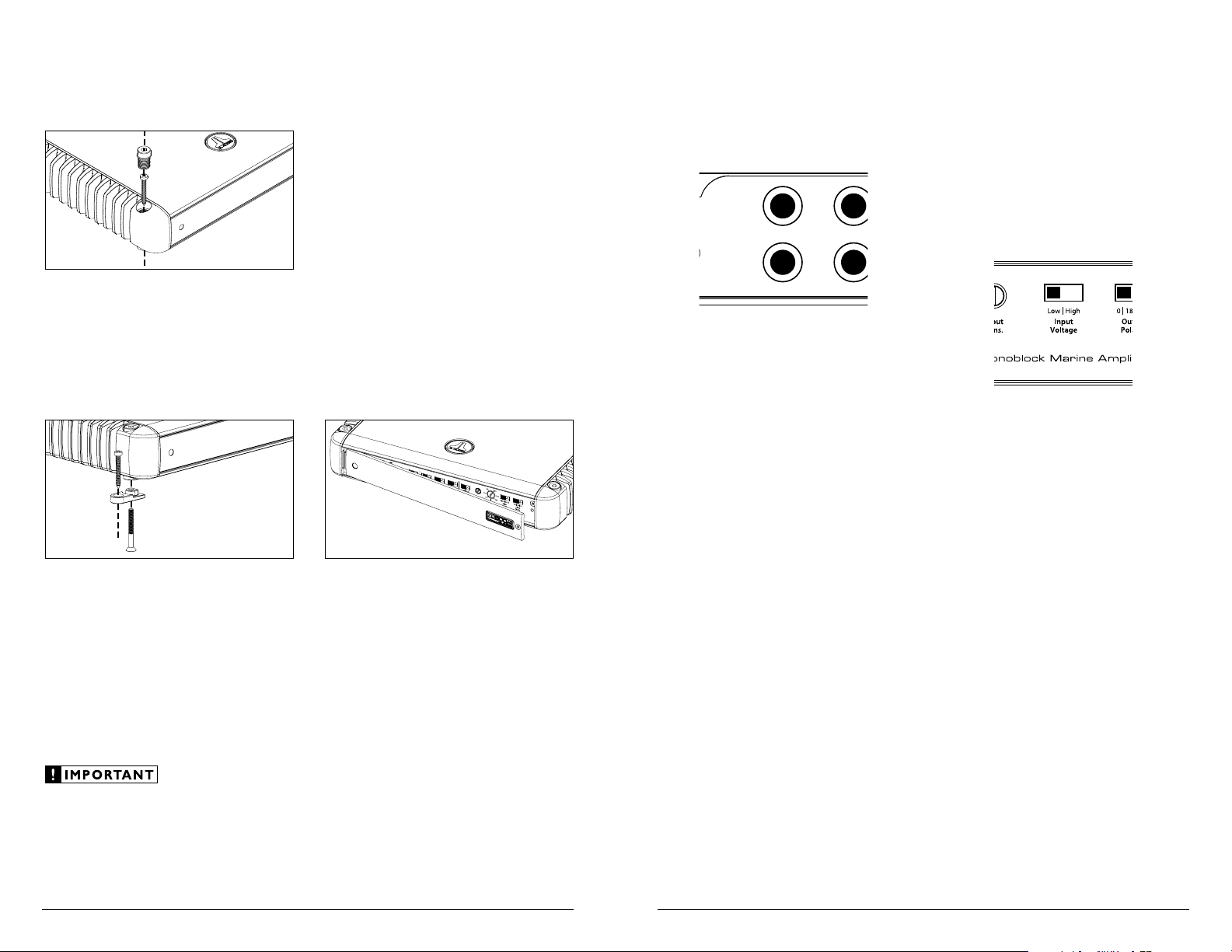
AMPLIFIER INPUTS
The MHD750/1 has a single input section
consisting of a pair of RCA-type input jacks on
the Connection Panel of the amplifier and a
pair of input controls on the Control Panel of
the amplifier: an “Input Voltage” switch and an
“Input Sens.” rotary control.
Remote
Level
Control
Inputs
L
R
L
R
+12 VDC Ground Remote
Preouts
+12 VDC Ground Remote
The MHD750/1 features stereo inputs, even
though it is a mono amplifier. This has been
done to permit the amplifier to sum stereo
input signals to mono, which is particularly
useful for driving subwoofers. Even if you
have a dedicated mono subwoofer signal
available or are feeding a left channel only or
a right channel only into the amplifier, you
must feed both inputs of the MHD750/1.
Connection of only one RCA input will result
in reduced power output, increased distortion
and can cause the amplifier to overheat. To
connect a mono signal to both inputs, use
an RCA “Y-Adaptor” (sold separately).
INPUT CONTROLS
On the amplifier’s control panel you will find
an “Input Voltage” range switch and a rotary
control labeled “Input Sens.” (Input Sensitivity).
These controls are designed to match the input
sensitivity of the MHD750/1 to the specific signal
source that is feeding it and must be adjusted,
with care, following the procedures outlined in
this manual. Failure to make correct adjustments
can result in weak output, excessive distortion
and/or undesirable noise in the audio output of
the amplifier!
“Input Voltage” Switch
A wide range of signal input voltages can be
accommodated by the MHD750/1’s differential-
balanced inputs (200mV – 8V RMS). This wide
range is split up into two sub-ranges, accessible via
the “Input Voltage” switch. The “Low” position
on the “Input Voltage” switch selects an input
sensitivity range between 200mV and 2V. This
means that the “Input Sens.” rotary control will
operate within that voltage window. If you are
using an aftermarket source unit, with preamp-
level outputs, this is most likely the position that
you will use (regardless of what voltage output
capability is claimed by the source unit).
The “High” position on the “Input Voltage”
switch selects an input sensitivity range between
800mV and 8V. This is for use with speaker-level
outputs from source units and small amplifiers
found in many OEM (factory-installed) systems.
To use speaker-level sources, splice the speaker
output wires of the source unit or small amplifier
onto a pair of RCA plugs for each input pair
or use the JL Audio ECS Speaker Wire to RCA
adaptor (XB-CLRAIC2-SW).
AMPLIFIER MOUNTING OPTIONS
The MHD750/1 has two mounting options to
ease in installation.
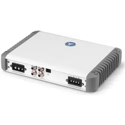
Standard Mounting
The standard method of mounting requires
removal of the four corner caps with the 3/16-inch
hex wrench included with your amplifier. Using
appropriate mounting screws (not included),
secure the amplifier in all four corners and
replace the corner caps.
Lateral Mounting Feet
Lateral Mounting Feet are also included
with your MHD750/1 to provide an alternative
mounting option. Each mounting foot
should be attached to the bottom of the
amplifier by screwing the provided bolt into
the bottom of the amplifier and up into the
corner cap with the supplied 1/8-inch hex
wrench. Next, using appropriate mounting
screws (not included), secure the amplifier
by its four Lateral Mounting Feet.
Check before drilling any holes in your vessel to
make sure that you will not be drilling through
a gas tank, brake line, wiring harness or other
vital vessel system.
CONTROL PANEL SECURITY COVER
The MHD750/1 features a Control Panel
Security Cover. When installed, the cover ensures
that your amplifier settings are not accidentally
changed while creating a clean aesthetic for the
amplifier and your installation. The control panel
security cover is pre-installed at the factory and
must be temporarily removed for access to the
controls described throughout this manual.
The security cover is secured by a single 2.5
mm hex-head screw at the far right of the panel.
Loosen the hex-head screw to release the security
cover (it is not necessary to completely remove the
screw). To re-install the security cover once all
adjustments have been made, insert the tongue on
the cover’s left edge into the groove where the left-
side heatsink meets the control panel, hinge the
panel closed and secure the screw using the
supplied 2.5 mm hex wrench. Do not overtighten
the screw.
Loading ...
Loading ...
Loading ...