Loading ...
Loading ...
Loading ...
6 | JL Audio - MHD750/1 Owner’s Manual
7
Ground Connection
The ground connection should be made using
the same gauge wire as the power connection.
It is common for the alternator to be grounded
through its chassis. If the alternator is not
grounded through its chassis and instead employs
a small (10 AWG - 6 AWG) wire to connect to
ground, this wire should also be upgraded to 4
AWG when installing amplifier systems with main
fuse ratings above 60A.
Many vessels employ small (10 AWG - 6 AWG)
wire to ground the battery to the vessel chassis
and to connect the alternator’s positive
connection to the battery. To prevent voltage
drops, these wires should be upgraded to 4
AWG pure copper wire when installing amplifier
systems with main fuse ratings above 60A.
Turn-On Wire
The MHD750/1 uses a conventional +12V
remote turn-on wire, typically controlled by
the source unit’s remote turn-on output. The
amplifier will turn on when +12V is present at
its “Remote” input and turn off when +12V is
switched off. If a source unit does not have a
dedicated remote turn-on output, the amplifier’s
turn-on lead can be connected to +12V via a
switch that derives power from an ignition-
switched circuit.
The MHD750/1’s “Remote” turn-on connector
is designed to accept 18 AWG – 12 AWG wire. 18
AWG is more than adequate for this purpose.
To connect the remote turn-on wire to the
amplifier, first back out the set screw on the
bottom of the Power Connector Plug, using the
supplied 2.5 mm hex wrench. Strip 1/2 inch
(12mm) of wire and insert the bare wire into the
receptacle, seating it firmly so that no bare wire
is exposed. When using smaller wire, it may
be necessary to strip 1 inch of insulation from
the wire and fold the bare wire in half prior to
insertion. While holding the wire in the terminal,
tighten the set screw firmly using the supplied
2.5 mm hex wrench, taking care not to strip the
head of the screw and making sure that the wire
is firmly gripped by the set screw.
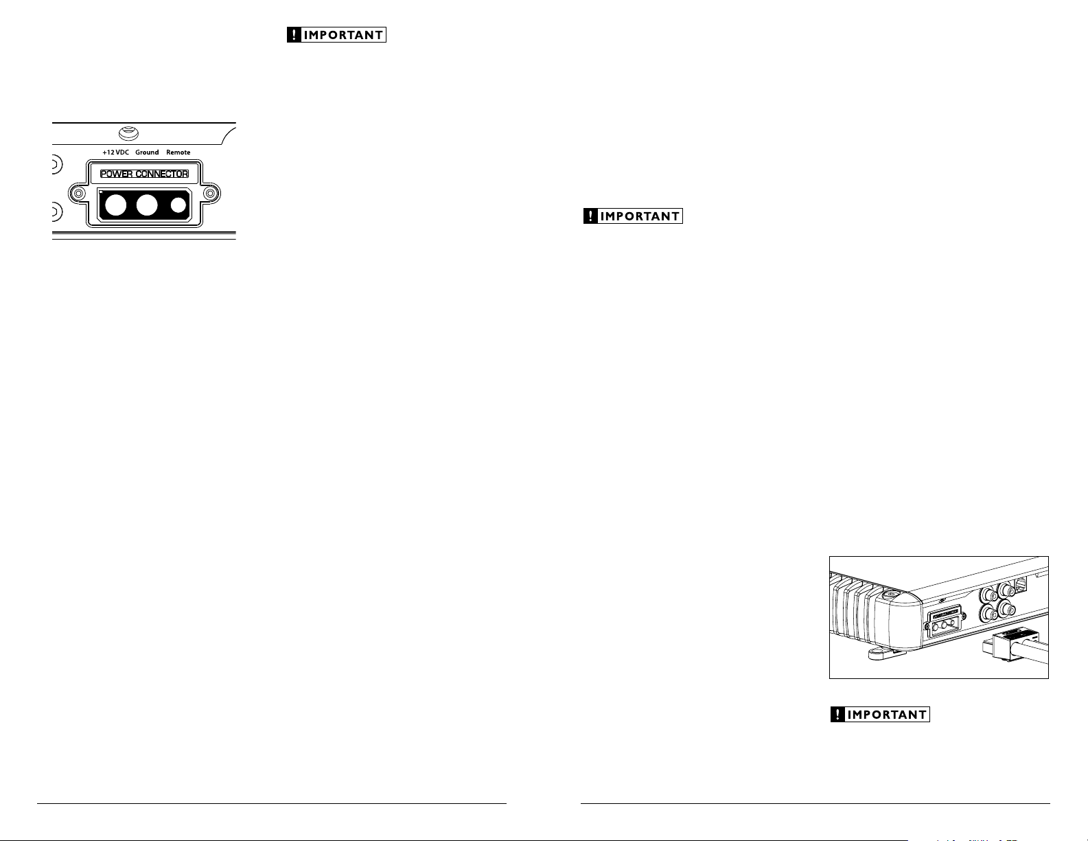
Amplifier Power Connector Plug
To connect the power wires and the remote
turn-on wire to the amplifier, unplug the power
connector plug from the amplifier chassis (pull
back firmly) and back out the set screws on
the connector plug, using the supplied 4 mm
hex wrench for the “+12 VDC” and “Ground”
connections and the supplied 2.5 mm hex wrench
for the “Remote” connection. Strip 3/8 inch (10
mm) of insulation from the end of each wire and
insert the bare wire into the receptacle on power
connector plug, seating it firmly so that no bare
wire is exposed. While holding each wire in place,
tighten each set screw firmly, taking care not to
strip the head of the screw.
Never make power connections with a “live”
wire. Always disconnect the negative battery
post before making any connections or
adjustments to a 12V power connection!
POWER AND TURNON CONNECTIONS
Before installing the amplifier, disconnect the
negative (ground) wire from the vessel’s battery.
This will prevent accidental damage to the system,
the vessel and your body during installation.
Remote
Level
Control
Inputs
L
R
L
R
+12 VDC Ground Remote
Preouts
+12 VDC Ground Remote
+12V Battery Connection
You will need to connect a power wire to
the vessel’s positive battery terminal, using an
appropriate power ring or specialized battery
terminal connector, such as the JL Audio
XB-BTU. This connection must be tight and
corrosion-free to ensure proper connectivity.
This wire MUST be fused appropriately for safety.
Any positive power wires run through barriers
must be protected with a high quality insulating
grommet to prevent damage to the insulation
of the wire. Failure to do so may result in a
dangerous short circuit.
Power Wire Requirements
The MHD750/1’s “+12 VDC” and “Ground”
connections are designed to accept 4 AWG power
wire. 4 AWG pure copper wire is recommended
for any power wire run longer than 72 inches (180
cm). For runs shorter than 72 inches, 8 AWG pure
copper power wire is acceptable.
If you are installing the MHD750/1 with other
amplifiers and wish to use a single main power
wire, use 2 AWG or 1/0 AWG pure copper wire
as a main power wire. This 2 AWG or 1/0 AWG
power wire should terminate into a distribution
block mounted as close to the amplifiers as
possible and should connect to the MHD750/1
with 4 AWG or 8 AWG pure copper power wire.
Please note that lower AWG numbers mean
bigger wire and vice-versa (1/0 AWG is the largest,
2 AWG is smaller, then 4 AWG, then 8 AWG, etc.).
We do not recommend the use of “copper-
clad aluminum wire” or “CCA” wire because
this wire is significantly less conductive than
pure copper wire. Only use pure copper power
wire, such as JL Audio’s MetaWire™. Tinned
copper wire (silver color) is acceptable as the
tin-plating is only a very minor component of
the wire.
Fuse Requirements
The installation of a fuse on each power wire,
within 18 wire inches (45 cm) of the positive
battery terminal is vital to protect the wire and
the vessel from fire in the event of a collision or
short-circuit. The fuse value at each power wire
should be high enough for all of the equipment
being run from that power wire.
If only the MHD750/1 is being run from
that power wire, we recommend a 60A fuse
be used. AGU (big glass fuse). AFS (small
blade fuse) or MaxiFuse™ (big plastic-
body fuse) types are recommended.
If other amplifiers are also being powered from
a main power wire and exceed 80 amps in total
fuse rating, we recommend the use of an ANL
(large-blade) fuse and holder. Each amplifier
must be fused independently at the outputs of
the power distribution block. Use JL Audio part
XC-FOA-2PAK and appropriate MaxiFuse™ type
fuses with JL Audio distribution blocks.
Please consult with your JL Audio
dealer to make sure that the wire, fuse
holder and fuse ratings are appropriate
for your system’s needs. The safety of
your installation depends on appropriate
power connections and fuse protection.
Loading ...
Loading ...
Loading ...