Loading ...
Loading ...
Loading ...
33
ENGLISH
Manual pipe detection
1. Enter the central control address into each indoor unit using its
wired remote control.
2. Turn No.1 of SW02M of HR unit PCB on.
3. Reset the power of HR unit PCB.
4. On the HR unit PCB, manually set address of each valve of the HR
unit to the central control address of the indoor unit connected to
the valve.
5. Reset the power of outside unit PCB.
6. The number of the indoor unit installed is displayed after about 5
minutes.
Ex) HR ➠ The number of the indoor
7. Reset the power of outside unit PCB, HR unit.
8. Manual pipe detection is completed
WARNING
1. Execute auto addressing and auto pipe detection again when-
ever the indoor PCB and HR unit PCB is replaced.
• Operation error occurs unless power is applied to the indoor
and HR units.
2. Error No.200 occurs if the number of connected indoor units and
that of scanned indoor units are different.
3. When auto pipe detection fails, complete it with manual pipe de-
tection (see Manual pipe detection).
4. When auto pipe detection addressing is completed normally,
manual pipe detection is not required.
5. If you want to do auto pipe detection again after auto pipe detec-
tion fails, do after reset of outside unit by all means.
6. During 5 minutes after pipe detection is completed, do not turn
off the main unit PCB to save the result of pipe detection auto-
matically.
!
WARNING
1. In case that central controller is not installed, remain the address
data after installer sets central control address as he wants
2. In case that central controller is installed, there would be central
control address in wired remote control of indoor unit.
3. In this case, set the HR unit manual pipe address according to
central control address of indoor unit.
4. Pipe which is not connected with indoor unit should be set differ-
ent address with pipe Connected with indoor unit.
(If addresses are piled up, corresponding valve is not working.
5. If you want to change the setting of manual pipe, you should do
it on HR unit PCB.
6. If an error occurred, it means that manual pipe setting is not
completed.
7. During 5 minutes after pipe detection is completed, do not turn
off the main unit PCB to save the result of pipe detection auto-
matically.
!
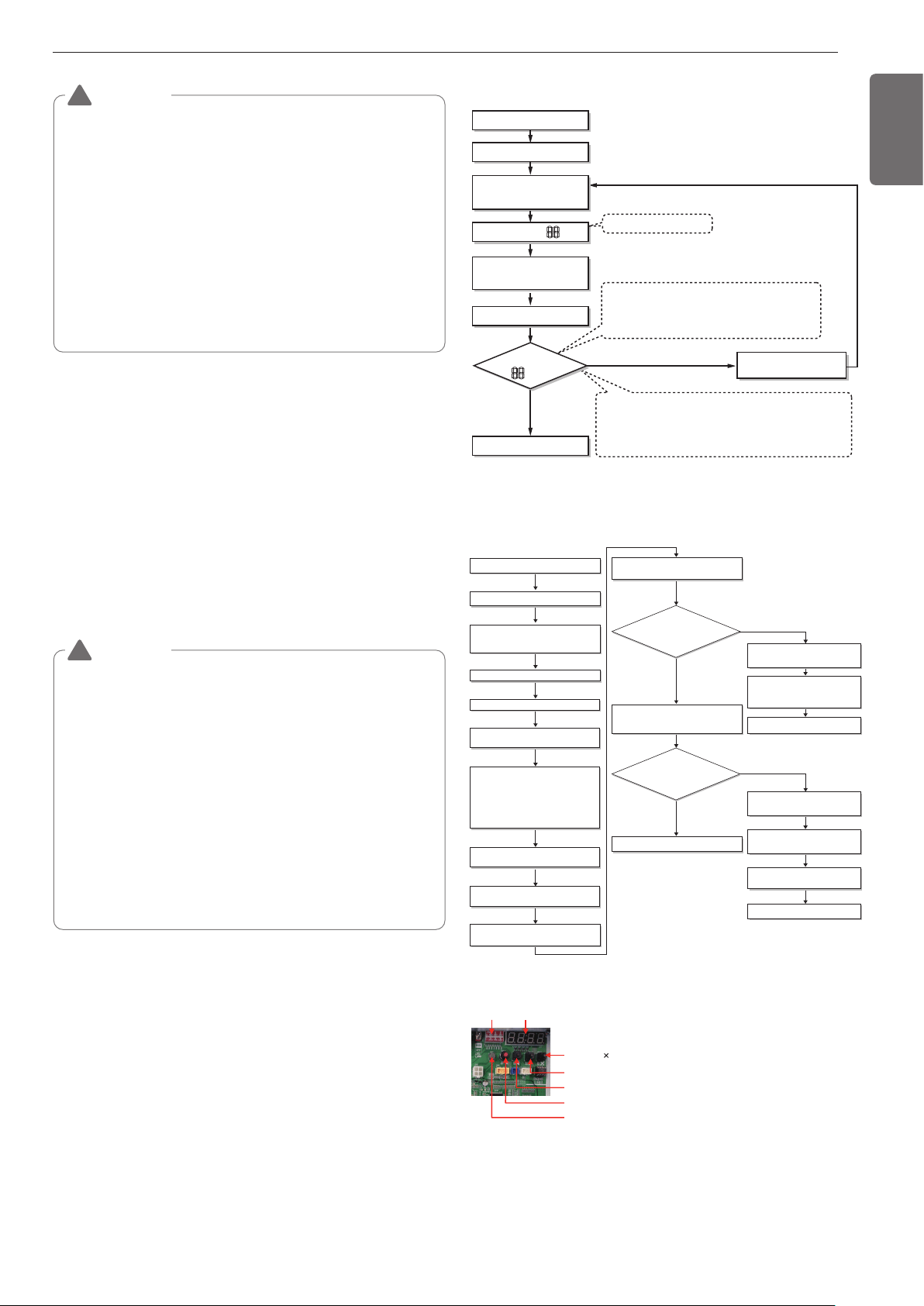
Flow chart of auto addressing for pipe detec-
tion
Completion of auto pipe detection
* It is possible to be generated mode changing noise of
heating and cooling which is normal.
There is no mode changing noise at normal operation.
Are the number
of indoor units connected to the
outside unit wiring and displayed
one equal?
Reset the power of HR unit PCB
Confirm that the setting of No.2, 3 of
SW02M corresponds with the number of
indoor units.
88' is displayed on 7-SEG of the outside
unit main PCB
Outside unit is operated for 5~60 minues.
The number of indoor units detected is
displayed for 30 seconds on the outside
unit PCB after outside unit stopped
Display error on outside unit PCB
Display error on HR unit PCB
Outside unit PCB : HR ơ HR unit
number ơ Valve number
HR unit : '200'
Check the HR unit and indoor unit
Pipe detection error occur after 30
seconds.
Check the installation of pipe of
outside, indoor, HR unit
Incompletion of auto pipe detection
Retry auto pipe detection after
checking trouble
Is the pipe
setting condition
satisfied during the operation of
indoor unit?
Confirmation of indoor unit address setting
Turn No.1 of SW02M of HR unit PCB off.
NO
NO
YES
YES
Master unit PCB DIP switch on : No.5
Select the mode using ‘ȯ’, ‘ȭ’ Button :
“Idu” Push the ‘Ɨ’ button
Select the mode using ‘ȯ’, ‘ȭ’ Button :
“Idu” Push the ‘Ɨ’ button
Select the “Id 6” function using ‘ȯ’, ‘ȭ’
Button :“StA” Push the ‘Ɨ’ button
Select the “Id 5” function using ‘ȯ’, ‘ȭ’
Button :“Ath” or ”Atc” Push the ‘Ɨ’ button.
Outdoor temperature is over 15°C(59°F) :
“Atc” Using (If it fail, use “Ath”)
Outdoor temperature is below 15°C(59°F) :
“Ath” Using (If it fail, use “Atc”)
DIP-SW01 7 - Segment
SW01C ( : confirm)
SW02C (ඔ : backward)
SW03C (ඖ : forward)
SW04C (
: cancel)
SW01D (reset)
The Procedure of Automatic Addressing
• Automatic addressing setting end
Numbers of indoor unit connection set whose
addressing is completed are indicated for 30seconds
on 7-segment LED after completing setting
Indoor address number is displayed on wired remote control or
indoor unit display window. It is not an error message, will
disappeared when on/off button is pressed on remote control
ex) Display of 01, 02, ..., 15 means connection of 15 indoor units
and Automatic addressing is completed normally.
Automatic addressing start
Waiting 3 minutes
Power On
Press RED Button for 5 sec.
(SW01C)
7-segment LED = 88
Don’t press RED Button
(SW01C)
Waiting about 2~7 minutes
7-segment LED
OK
YES
NO Check the connections
of communication cable
= 88
Loading ...
Loading ...
Loading ...