Loading ...
Loading ...
Loading ...
13
ENGLISH
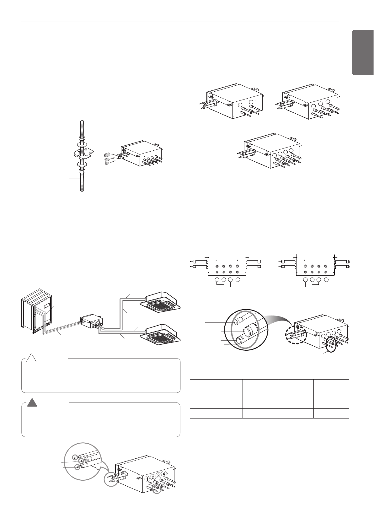
Six-sided Nut
(M10 or M8)
Hanger metal
Hanger metal
Hanger metal
Flat washer
Flat washer
Flat washer
(M10)
Hanging bolt
Hanging bolt
Hanging bolt
(M10 or M8)
A
Insulation
Installation procedure for HR unit
1. Using an insert-hole-in- anchor, hang the hanging bolt.
2. Install a hexagon nut and a flat washer (locally-procured)to the hang-
ing bolt as shown in the figure in the bottom, and fit the main unit to
hang on the hanger metal.
3. After checking with a level that the unit is level, tighten the hexagon
nut.
* The tilt of the unit should be within ±5° in front/back and left/right.
4. This unit should be installed suspended from ceiling and side A
should always be
facing up.
5. Insulate not used pipes completely as shown in the figure.
Type of HR Unit
Select an HR unit according to the number of the indoor units to be in-
stalled. HR units are classified into 3 types by the number of con-
nectable indoor units.
Ex) Installation of 6 indoor units
Consists of HR unit for 4 branches and HR unit for 2 branches.
Joint Method of HR Unit (Big Duct : ARNU76GB8-,
ARNU96GB8-)
Joint Method is required when B5/B8 chassis is installed. In Joint
Method, two neighboring outlets of one HR unit are linked by Y branch
pipe and connected to one indoor unit.
Gas pipe
Gas pipe
Liquid pipe
Liquid pipe
HR Unit
1
2
3
4
High pressure Gas pipe
Liquid pipe
Low pressure
Gas pipe
Whenever connecting the indoor units with the HR unit, install the in-
door units in numerical order from No.1.
Ex) In case of installing 3 indoor units : No. 1, 2, 3 (O), No. 1, 2, 4 (X),
No.1, 3, 4 (X), No.2, 3, 4 (X).
CAUTION
!
PRHR031(3 branches)PRHR021(2 branches)
1
2
1
3
2
PRHR041(4 branches)
1
2
3
4
1
st
HR Unit 2
nd
HR Unit
1 2 3 4
B8
(96k) (28k)
BG
1 2 3 4
B8
(76k)(21k)
BH
Installation of Outside Unit, HR Unit, Indoor Unit
Refrigerant Pipe
3 pipes are connected to the HR unit from the outside unit, classified
into liquid pipe, low pressure gas pipe and high pressure gas pipe de-
pending on status of refrigerant passing through the pipe.
You must connect 3 pipes from outside unit to HR unit.
For connection between indoor unit and HR unit, you must connect
both liquid pipe and gas pipe from the HR unit to the indoor unit. In this
case, connect them to the indoor unit starting from No.1 connection
port of the HR unit (the port number is displayed on ports of the HR
unit). Use auxiliary flare as annexed parts in connection to the indoor
unit.
WARNING
Before brazing work, remove gas in the HR Unit by cutting the three
pipes in the small circles on the figure.
If not, it may cause injuries.
Remove the caps before connecting pipes.
!
Gas pipe Ø15.88 (5/8)
Liquid pipe Ø9.52 (3/8)
Brazing Type
Liquid pipe
Liquid pipe
Low pressure gas pipe
Low pressure gas pipe
High pressure gas pipe
High pressure gas pipe
Liquid pipe
Low pressure gas pipe
High pressure gas pipe
(Brazing Type)
Gas pipe Ø15.88 (5/8)
Liquid pipe Ø9.52 (3/8)
Brazing Type
1
2
3
4
Remove caps on
The brazing part.
Liquid pipe
Low pressure gas pipe
High pressure gas pipe
Unit : mm(inch)
HR unit PRHR021A PRHR031A PRHR041A
Low pressure gas pipe Ø22.2(7/8) Ø28.58(1-1/8) Ø28.58(1-1/8)
High pressure gas pipe Ø19.05(3/4) Ø22.2(7/8) Ø22.2(7/8)
Liquid pipe Ø9.52(3/8) Ø12.7(1/2) Ø15.88(5/8)
Loading ...
Loading ...
Loading ...