Loading ...
Loading ...
Loading ...
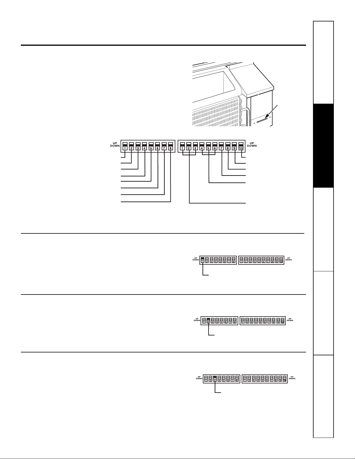
The auxiliary dip switch controls are located
behind the room cabinet, through an opening
below the control panel.
Remove the room cabinet. See the To Remove the
Room Cabinet section.
The owner is responsible for checking switches
and ensuring they are in the desired position.
5
Auxiliary Controls on your Zoneline. ge.com
Auxiliary Controls – Dip Switches
Safety Instructions Operating Instructions Care and Cleaning Troubleshooting Tips Consumer Support
All Electric Heat
When this switch is enabled (UP), heat pump
operation is locked out, causing the unit to
provide only electric resistance heat.
Cooling–Smart Fan
When this switch is enabled (UP), it allows the
indoor fan to cycle on/off with the compressor.
When this switch is disabled (DOWN), it allows
the indoor fan to run continuously.
Heating–Smart Fan
When this switch is enabled (UP), it allows the
indoor fan to run continuously. When this
switch is disabled (DOWN), it allows the indoor
fan to cycle on/off with the heat pump or
heater operation.
ALLI
2
R (All Electric Heat)
C: FAN CN (Cooling–Smart Fan)
H: FAN CY (Heating–Smart Fan)
ALLI
2
R (All Electric Heat)
C: FAN CN (Cooling–Smart Fan)
H: FAN CY (Heating–Smart Fan)
CLASS 2 (Remote Thermostat)
LOAD SHEDDING (CDC)
FREEZ Sen (Freeze Sentinel)
CONST FAN (Constant ON Fan)
OCCUPIED (Occupancy Sensor)
Reserved for future use
DIAGNOS (Diagnostic Check)
BOOST (Heat Boost Operation)
HEAT S (Heat Sentinel)
TL1 (H) (Temp. Limit 1–Heat)
TL2 (H) (Temp. Limit 2–Heat)
TL3 (H) (Temp. Limit 3–Heat)
TL1 (C) (Temp. Limit 1–Cool)
TL2 (C) (Temp. Limit 2–Cool)
TL3 (C) (Temp. Limit 3–Cool)
Dip Switches
Loading ...
Loading ...
Loading ...