
ASSEMBLY MANUAL / OWNER’S MANUAL
230i
This product is compliant with the
applicable CE requirements.

2
TABLE OF CONTENTS
To validate warranty support, keep the original proof of purchase and record the following information:
Serial Number __________________________
Date of Purchase ____________________
To register your product warranty, contact your local distributor.
If you have questions or problems with your product, please contact your local Schwinn distributor.
To nd your local distributor, go to: www.nautilusinternational.com
Nautilus, Inc., www.nautilusinternational.com | Nautilus, Inc., 18225 NE Riverside Parkway, Portland, OR 97230 USA | Printed in
China | © 2016 Nautilus, Inc. | ® indicates trademarks registered in the United States. These marks may be registered in other nations
or otherwise protected by common law. Schwinn, the Schwinn Quality logo, Schwinn 230i, Schwinn Connect, Bowex, Nautilus, and
Universal are trademarks owned by or licensed to Nautilus, Inc. MyFitness Pal
®
is a registered trademark of its owner.
ORIGINAL MANUAL - ENGLISH VERSION ONLY
Important Safety Instructions 3
Safety Warning Labels / Serial Number 5
Specications 6
Before Assembly 6
Parts 7
Hardware 8
Tools 8
Assembly 9
Moving the Machine 19
Leveling the Machine 20
Features 21
Console Features 22
Operations 27
Adjustments 27
Power Up / Idle Mode 27
Initial Setup 28
Quick Start Program 28
User Proles 28
Prole Programs 30
Pausing or Stopping 33
Results / Cool Down Mode 33
GOAL TRACK Statistics 33
Console Service Mode 35
Maintenance 36
Maintenance Parts 37
Troubleshooting 39

3
IMPORTANT SAFETY INSTRUCTIONS
This icon means a potentially hazardous situation which, if not avoided, could result in death or serious
injury.
Obey the following warnings:
Read and understand all warnings on this machine.
Carefully read and understand the Assembly instructions.
• Keep bystanders and children away from the product you are assembling at all times.
• Do not connect power supply to the machine until instructed to do so.
• Do not assemble this machine outdoors or in a wet or moist location.
• Make sure assembly is done in an appropriate work space away from foot trafc and exposure to bystanders.
• Some components of the machine can be heavy or awkward. Use a second person when doing the assembly
steps involving these parts. Do not do steps that involve heavy lifting or awkward movements on your own.
• Set up this machine on a solid, level, horizontal surface.
• Do not try to change the design or functionality of this machine. This could compromise the safety of this machine
and will void the warranty.
• If replacement parts are necessary, use only genuine Nautilus replacement parts and hardware. Failure to use
genuine replacement parts can cause a risk to users, keep the machine from operating correctly and void the
warranty.
• Do not use until the machine has been fully assembled and inspected for correct performance in accordance with
the Manual.
• Read and understand the complete Manual supplied with this machine before rst use. Keep the Manual for future
reference.
• Do all assembly steps in the sequence given. Incorrect assembly can lead to injury or incorrect function.
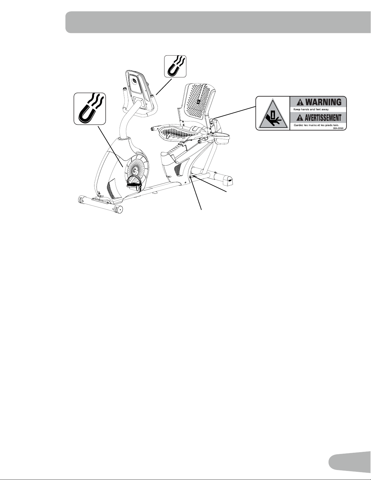
• This product contains magnets. Magnetic elds can interfere with the normal use of certain medical devices at
a close range. Users may come into proximity of the magnets in the assembly, maintenance, and/or use of the
product. Given the obvious importance of these devices, such as a pacemaker, it is important that you consult
with your medical provider in connection with the use of this equipment. Please consult the “Safety Warning
Labels and Serial Number” section to determine the location of the magnets on this product.
Before using this equipment, obey the following warnings:
!
Read and understand the complete Manual. Keep the Manual for future reference.
Read and understand all warnings on this machine. If at any time the Warning stickers become loose,
unreadable or dislodged, contact your local distributor for replacement stickers.
• Children must not be let on or near to this machine. Moving parts and other features of the machine can be
dangerous to children.
• Not intended for use by anyone under 14 years of age.
• Consult a physician before you start an exercise program. Stop exercising if you feel pain or tightness in your
chest, become short of breath, or feel faint. Contact your doctor before you use the machine again. Use the
values calculated or measured by the machine’s computer for reference purposes only.
• Before each use, examine this machine for loose parts or signs of wear. Do not use if found in this condition.
Monitor the Seat, Pedals, and Crank Arms closely. Contact your local distributor for repair information.
• Maximum user weight limit: 136 kg (300 lbs.). Do not use if you are over this weight.
• This machine is for home use only.
• Do not wear loose clothing or jewelry. This machine contains moving parts. Do not put ngers or other objects into
moving parts of the exercise equipment.

4
• Set up and operate this machine on a solid, level, horizontal surface.
• Make the Pedals stable before you step on them. Use caution when you step on and off the machine.
• Disconnect all power before servicing this machine.
• Do not operate this machine outdoors or in moist or wet locations. Keep the foot pedals clean and dry.
• Keep at least 0.6 m (24”) on each side of the machine clear. This is the recommended safe distance for access
and passage around and emergency dismounts from the machine. Keep third parties out of this space when
machine is in use.
• Do not over exert yourself during exercise. Operate the machine in the manner described in this manual.
• Correctly adjust and safely engage all Positional Adjustment Devices. Make sure that the Adjustment Devices do
not hit the user.
• Exercise on this machine requires coordination and balance. Be sure to anticipate that changes in speed and
resistance level can occur during workouts, and be attentive in order to avoid loss of balance and possible injury.
• This appliance is not intended for use by persons (including children) with reduced physical, sensory or mental
capabilities, or lack of experience and knowledge, unless they have been given supervision or instruction
concerning use of the appliance by a person responsible for their safety.
5
SAFETY WARNING LABELS
AND SERIAL NUMBER
Serial Number
Product
specification
REVISIONS
ECO
REVISION
REV DESCRIPTION
APPROVED
DATE
TITLE.
PART NO.
REV.
SHEET 1 OF 1
SCALE: 1:1
DO NOT SCALE DRAWING
1. ALL ITEMS MUST BE RoHS COMPLIANT
2. ALL DIMENSIONS APPLY BEFORE PLATING OR COATING.
3. REMOVE ALL BURRS, BREAK SHARP EDGES 0.5 MM MAX.
4. ALL MACHINES SURFACES Ra 3.2 uM.
5. ALL APPLICABLE NAUTILUS STANDARDS AND
SPECIFICATIONS APPLY.
6. ALL DIMENSIONS ARE IN MILLIMETERS
7. ALL DUAL DIMENSIONS ARE IN INCH
UNLESS OTHERWISE SPECIFIED:
METRIC
THIRD ANGLE
PROJECTION
INTERPRET DIMENSIONS AND TOLERANCES
PER ASME Y14.5M - 1994
2.5
1.5
0.75
0.25
1°
X.
X.X
X.XX
X.XXX
ANGULAR
C
SIZE
This document is the property of Nautilus, Inc. It may not be reproduced in whole or part, provided to third parties, or used for any purposes other than the performance of work for Nautilus, Inc. without written authorization. All rights are reserved, including copyrights.
TOLERANCES.
DRAWN
DESIGNED
DATE
METRIC_C_REV G
NAUTILUS, INC.
16400 SE NAUTILUS DRIVE, VANCOUVER, WA 98683
LIFECYCLE
7-22-10
APPROVALS
- -
- - - -
WARRANTY ITEM:
A RELEASED
NPI 13149 DLOVELY
7-22-10
D.LOVELY
D.LOVELY
07 /22 / 2010
D.LOVELY
A
004-0930
CRUSH WARNING
21.78mm
54.8mm
MATERIAL.
COLOR.
DIE LINE
PMS 152
PMS 109
BLACK
WHITE
Labels must be created from an agency approved tamper proof labeling system
such as "UL Recognized component marking and labeling system (example: UL PGGU2) or equivalent.
Label and adhesive must be rated for surface it is applied to (painted metal or ABS plastic),
Label and adhesive must be rated for 60 degrees C minimum. Labels must meet UL 1647 Permanence of Marking Test.
•
•
6
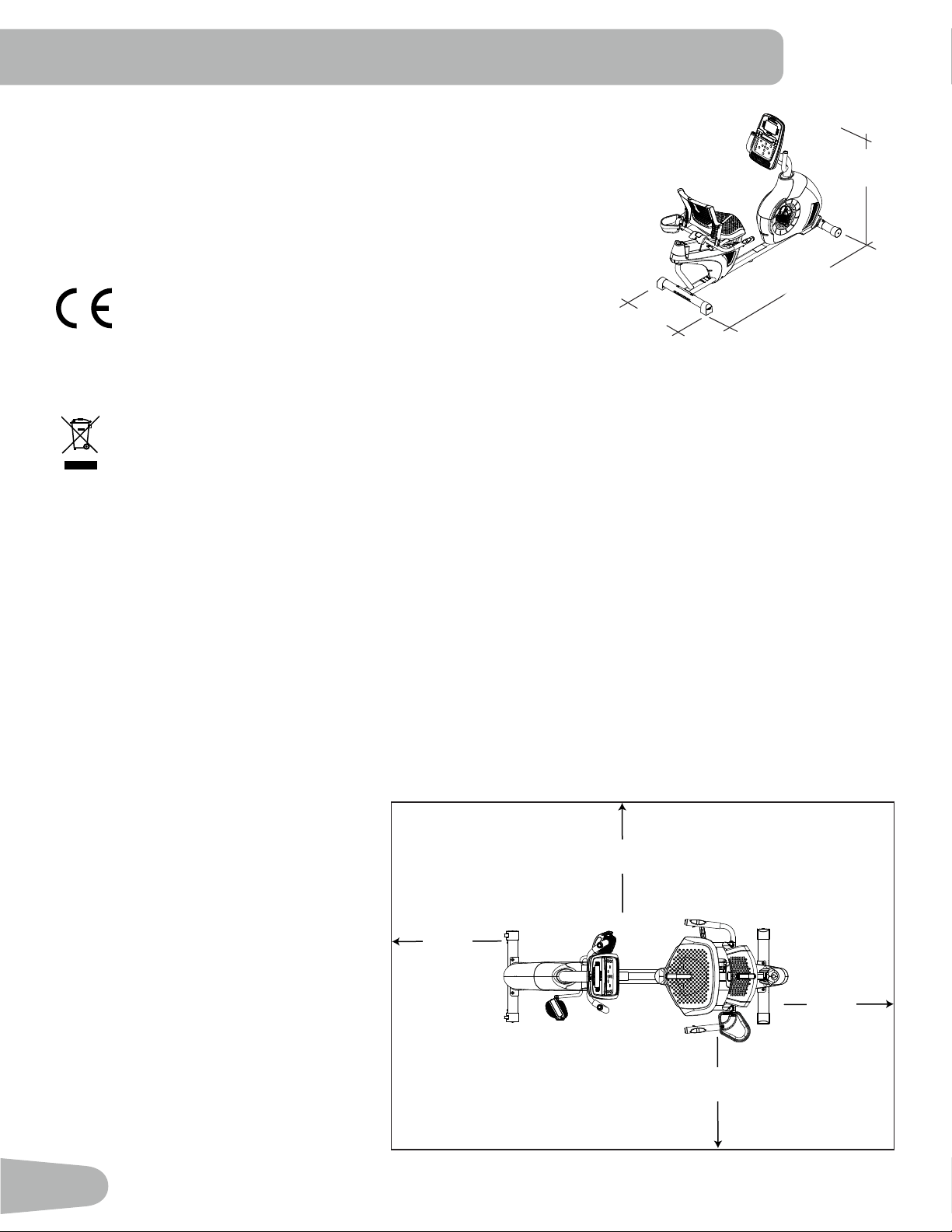
SPECIFICATIONS
Before Assembly
Select the area where you are going to set up and operate your machine. For safe operation, the location must be on a
hard, level surface. Allow a workout area of a minimum 1.9 m x 2.8 m ( 75” x 112” ).
Basic Assembly Tips
Follow these basic points when you assemble your machine:
• Read and understand the “Important Safety Instructions” before assembly.
• Collect all the pieces necessary for each assembly step.
• Using the recommended wrenches, turn the bolts and nuts to the right (clockwise) to tighten, and the left (counter-
clockwise) to loosen, unless instructed otherwise.
• When attaching 2 pieces, lightly lift
and look through the bolt holes to help
insert the bolt through the holes.
• The assembly can require 2 people.
Maximum User Weight: 136 kg ( 300 lb )
Machine Weight: 37 kg ( 81.57 lb )
Total Surface Area (foot print) of equipment: 10,705.5 cm
2
( 1662.5 inches
2
)
Power Requirements:
Operational Voltage: 220V - 240V AC, 50Hz
Operating Current: 0.4A
Complies with the following:
ISO 20957 compliant.
DO NOT dispose of this product as refuse. This product is to be recycled. For proper disposal of this product,
please follow the prescribed methods at an approved waste center.
126.8 cm
(49.9”)
162.5 cm
(64”)
70.3 cm
(27.7”)
2.8m (112”)
1.9m
(75”)
0.6m
( 24” )
0.6m
( 24” )
0.6m
( 24” )
0.6m
( 24” )
7
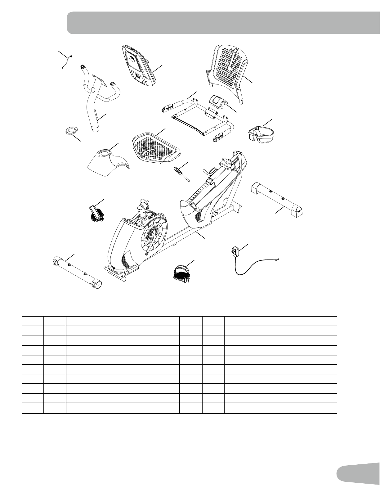
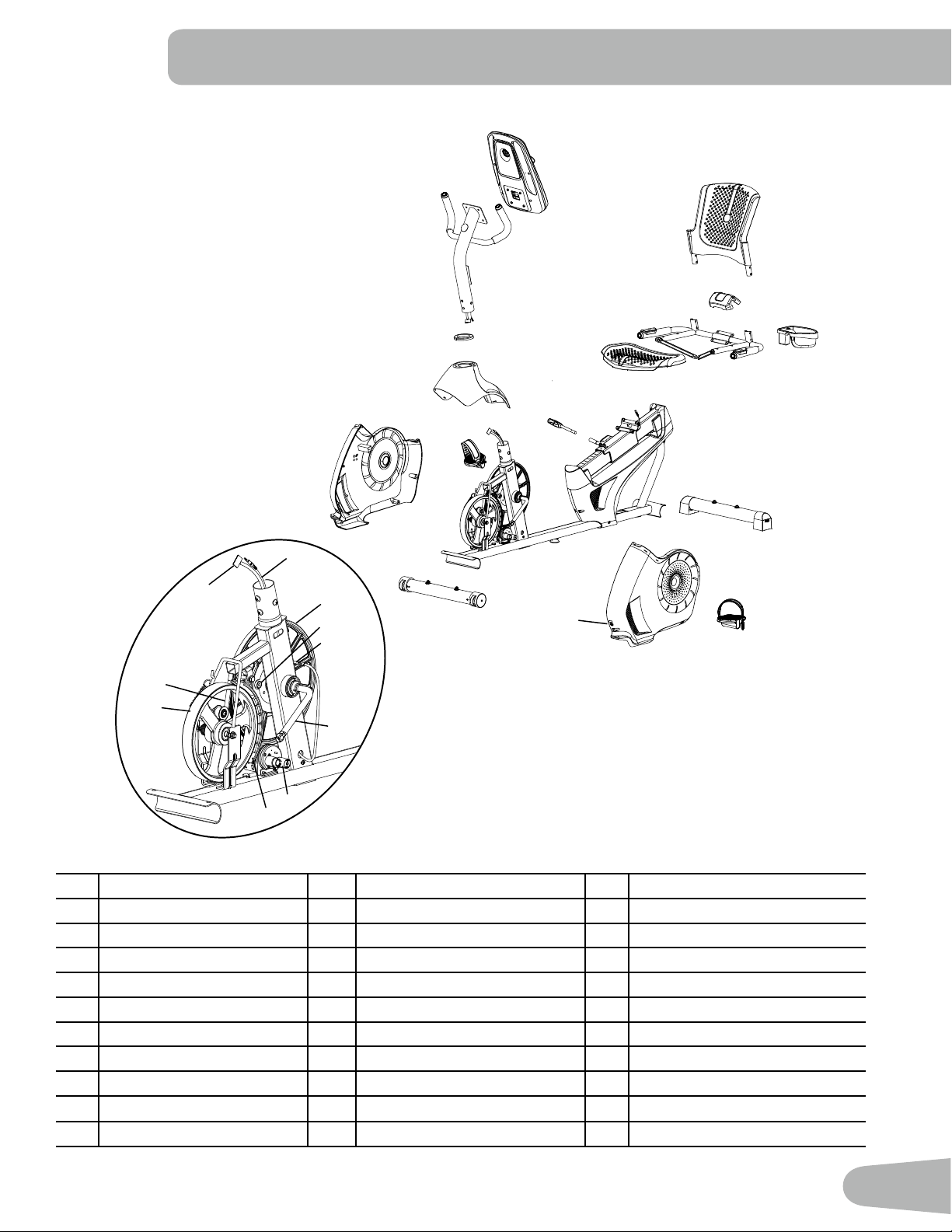
Item Qty Description Item Qty Description
1 1 Console 10 1 AC Adapter
2 1 Water Bottle Holder 11 1 Left Pedal
3 1 Seat Back 12 1 Front Stabilizer
4 1 Cover 13 1 Right Pedal
5 1 Seat Frame Assembly 14 1 Upper Shroud
6 1 Seat Bottom 15 1 Shroud Cap
7 1 Seat Adjustment Handle 16 1 Console Mast
8 1 Rear Stabilizer 17 1 MP3 Cord
9 1 Frame
PARTS
4
1
2
5
16
6
14
15
9
7
13
12
11
8
3
10
17
8
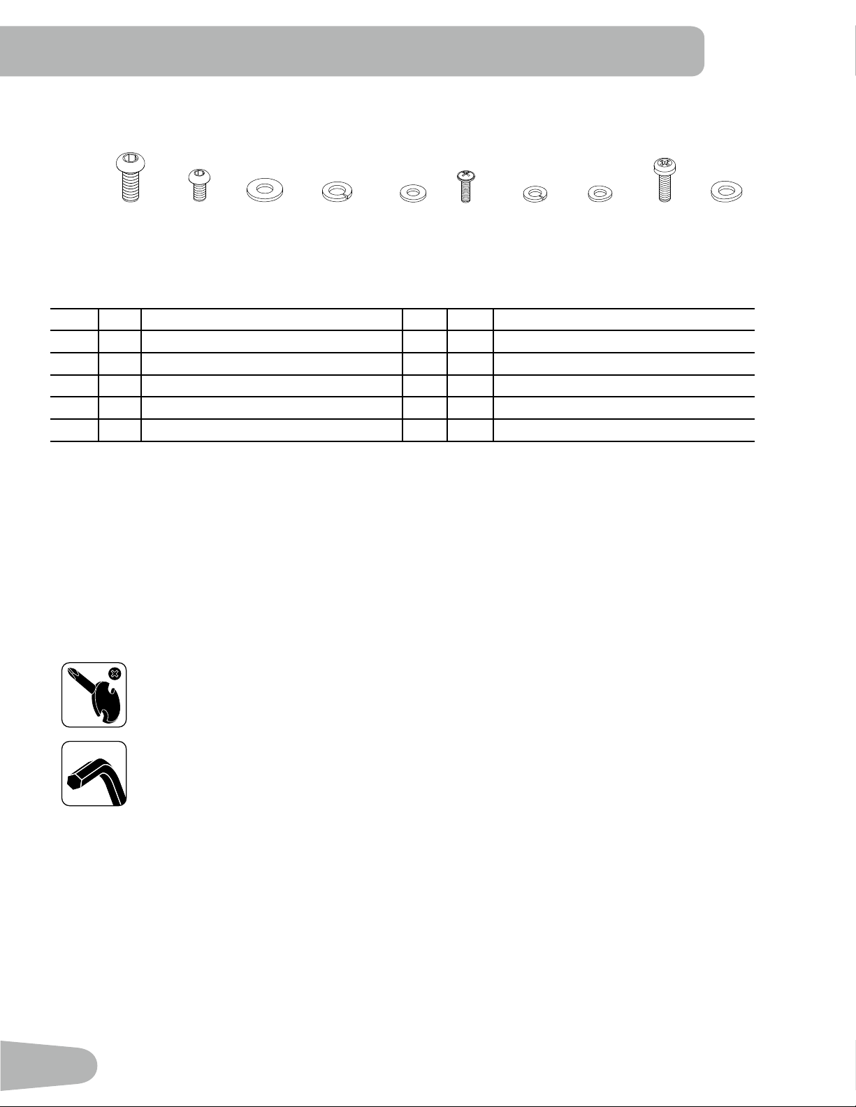
HARDWARE / TOOLS
Tools
Included
4 mm
6 mm
Item Qty Description Item Qty Description
A 8 Button Head Hex Screw, M8x20 F 2 Phillips Head Screw, M5x12
B 10 Button Head Hex Screw, M6x12 G 14 Lock Washer, M6
C 4 Flat Washer, M8 H 4 Curved Washer, M6
D 8 Lock Washer, M8 I 4 Phillips Head Screw, M6x25
E 10 Flat Washer, M6 J 4 Curved Washer, M8
A B C D E F
G H
I J
Note: Select pieces of Hardware have been provided as spares on the Hardware Card. Be aware that there may be
remaining Hardware after the proper assembly of your machine.
9
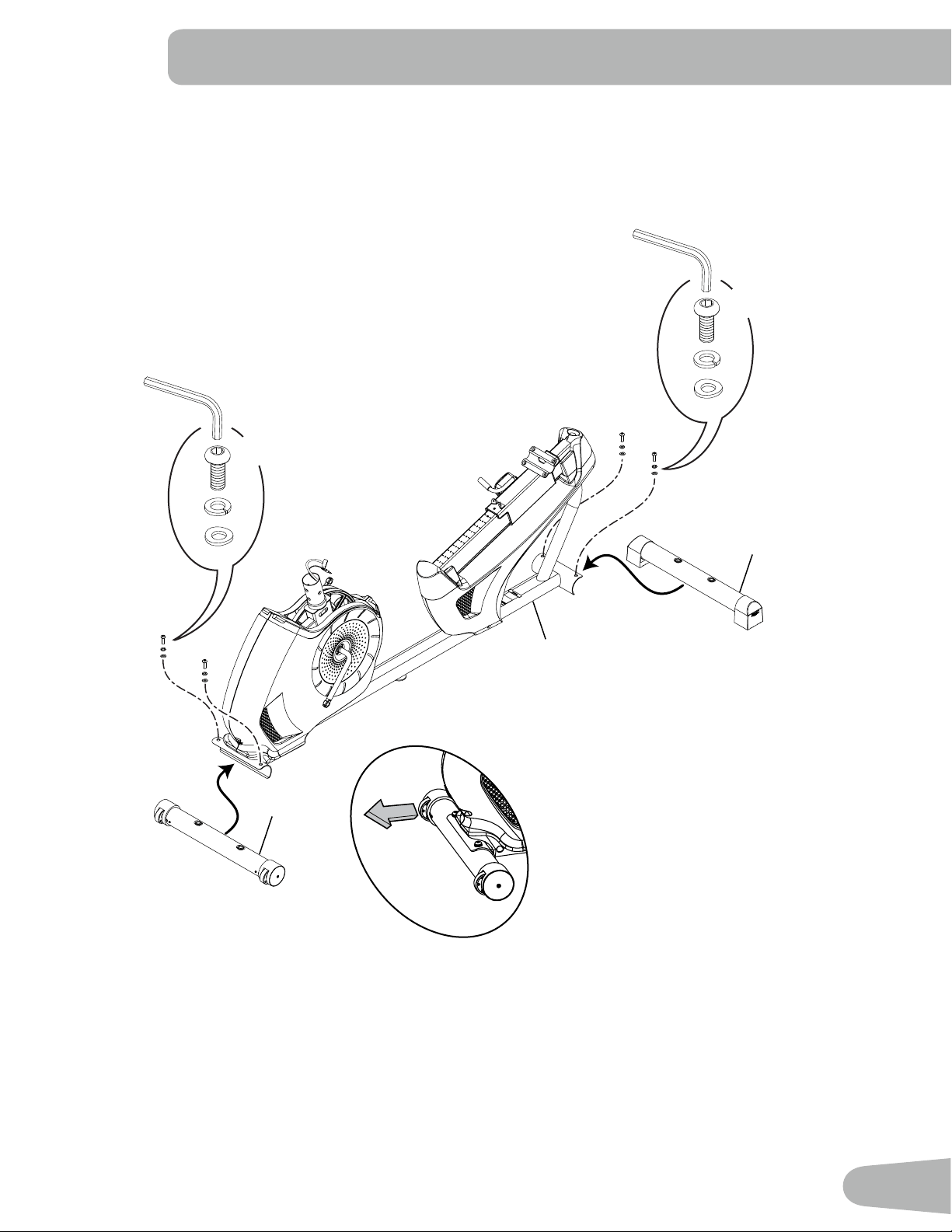
ASSEMBLY
1. Attach Stabilizers to Frame
Note: Hardware is pre-installed and not on the Hardware Card. *
*
6mm
12
8
9
*
*
X2
*
6mm
*
*
X2
10
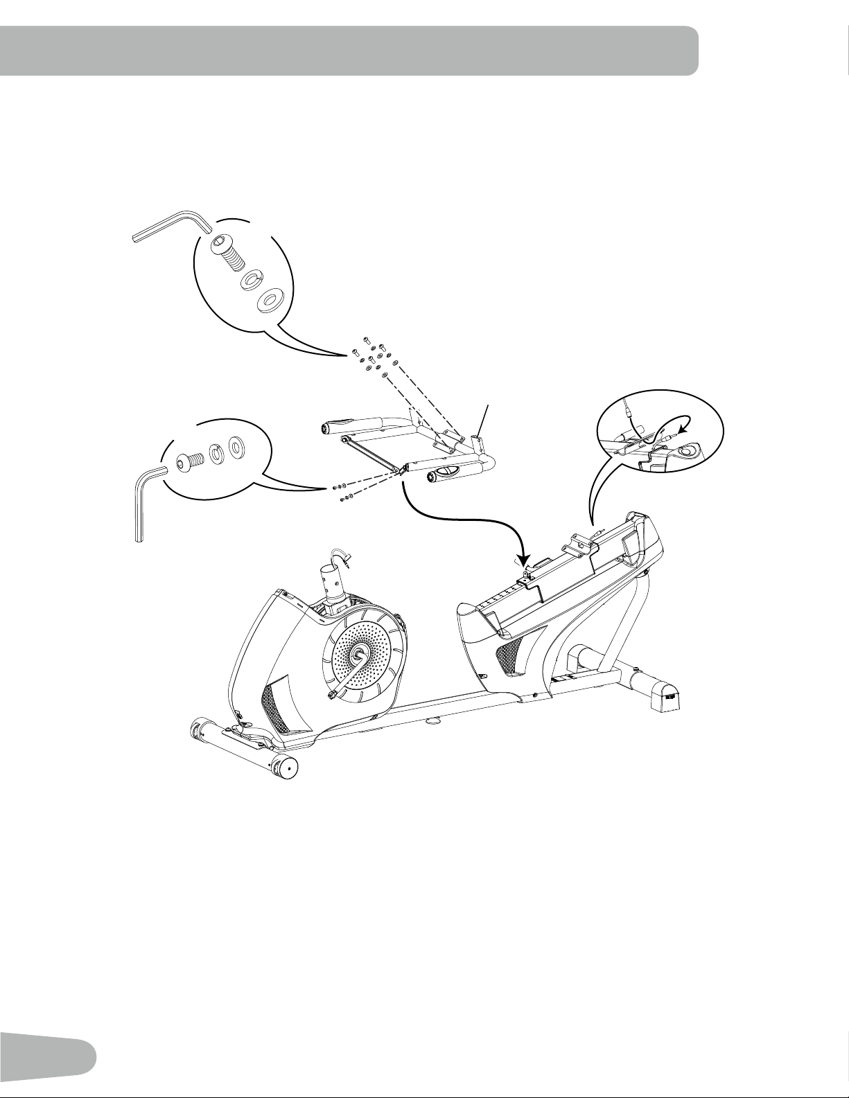
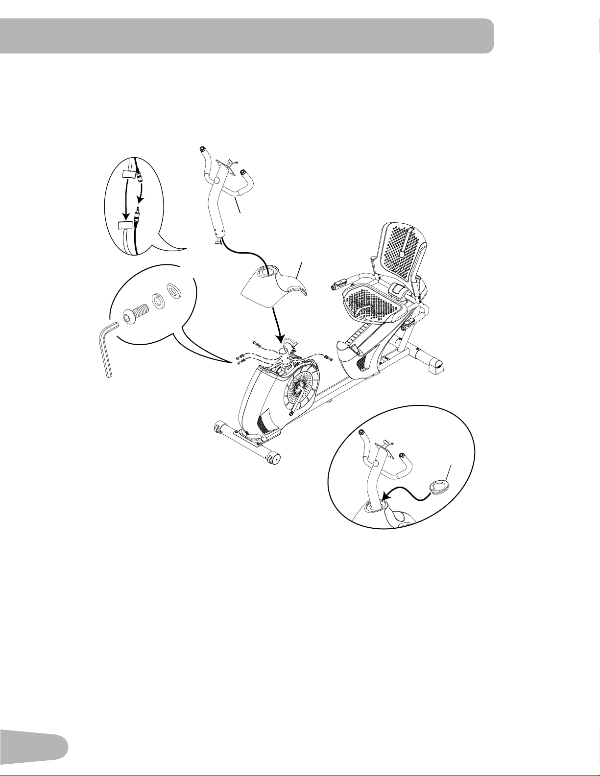
2. Attach the Seat Frame Assembly to the Seat Rail
NOTICE: Do not crimp the Heart Rate Cable. Once all hardware has been inserted, be sure to fully tighten it.
B
E
G
4mm
X2
5
A
C
D
6mm
X4
11
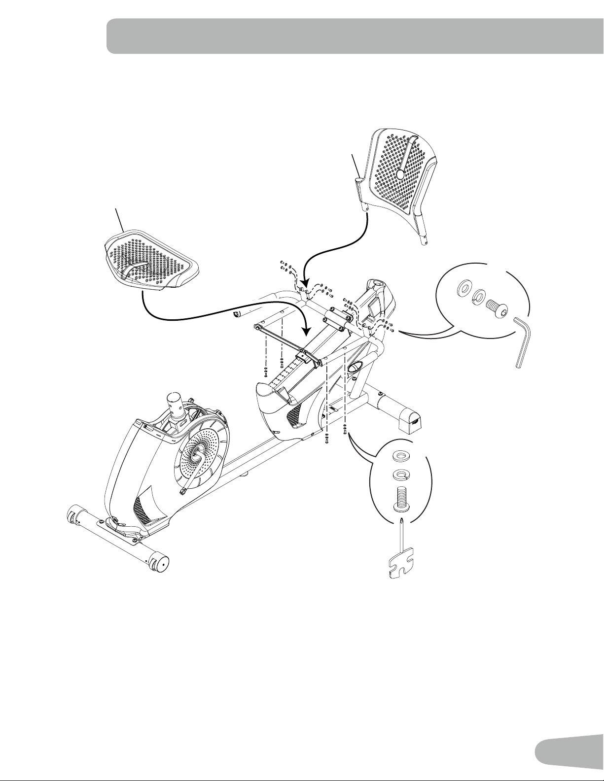
3. Attach Seat Pads to Seat Frame Assembly
3
6
X8
4mm
B
E
G
H
X4
#2
G
I
12
4. Attach Cover to Frame Assembly
4
13
5. Attach Seat Adjustment Handle to Frame Assembly
7
14
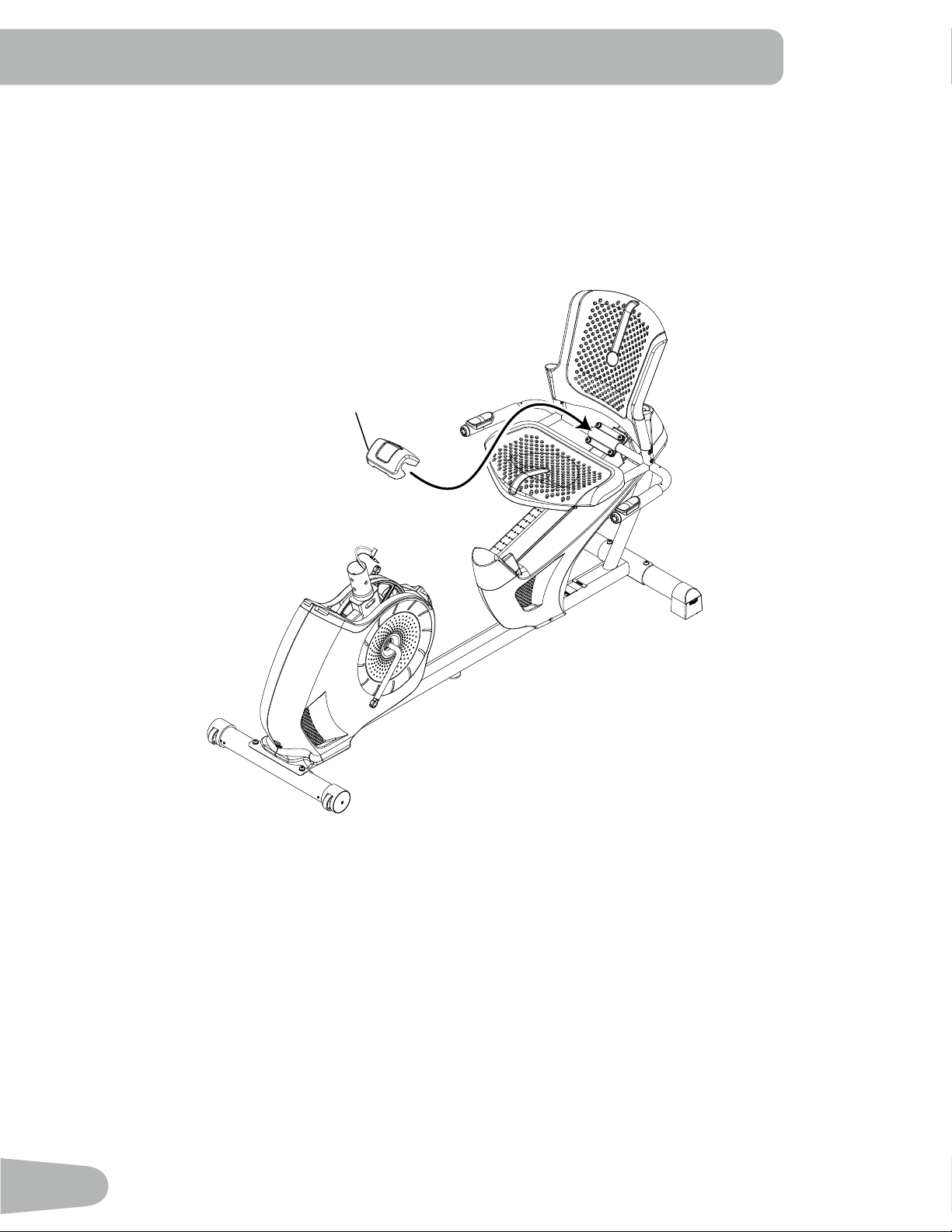
6. Connect the Cables and Attach the Console Mast to Frame Assembly
NOTICE: Do not crimp Console Cables.
15
A
J
6mm
X4
16
14
D
15
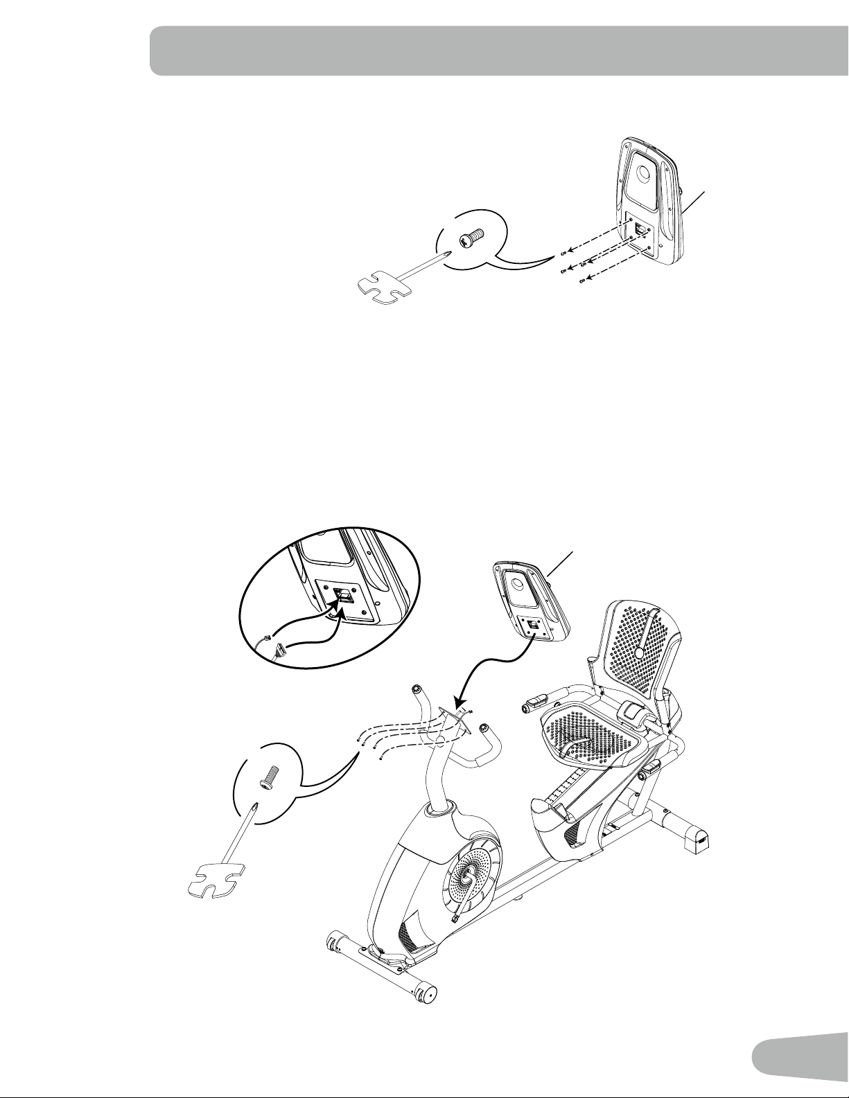
7. Remove Hardware from Console
NOTICE: Do not crimp the cable.
Note: Hardware is pre-installed and not on the Hardware Card. *
8. Connect Cables and Attach Console to Frame Assembly
NOTICE: Align the clips on the cable connectors and make sure the connectors lock. Do not crimp cables.
*
X4
1
1
*
X4
#2
16
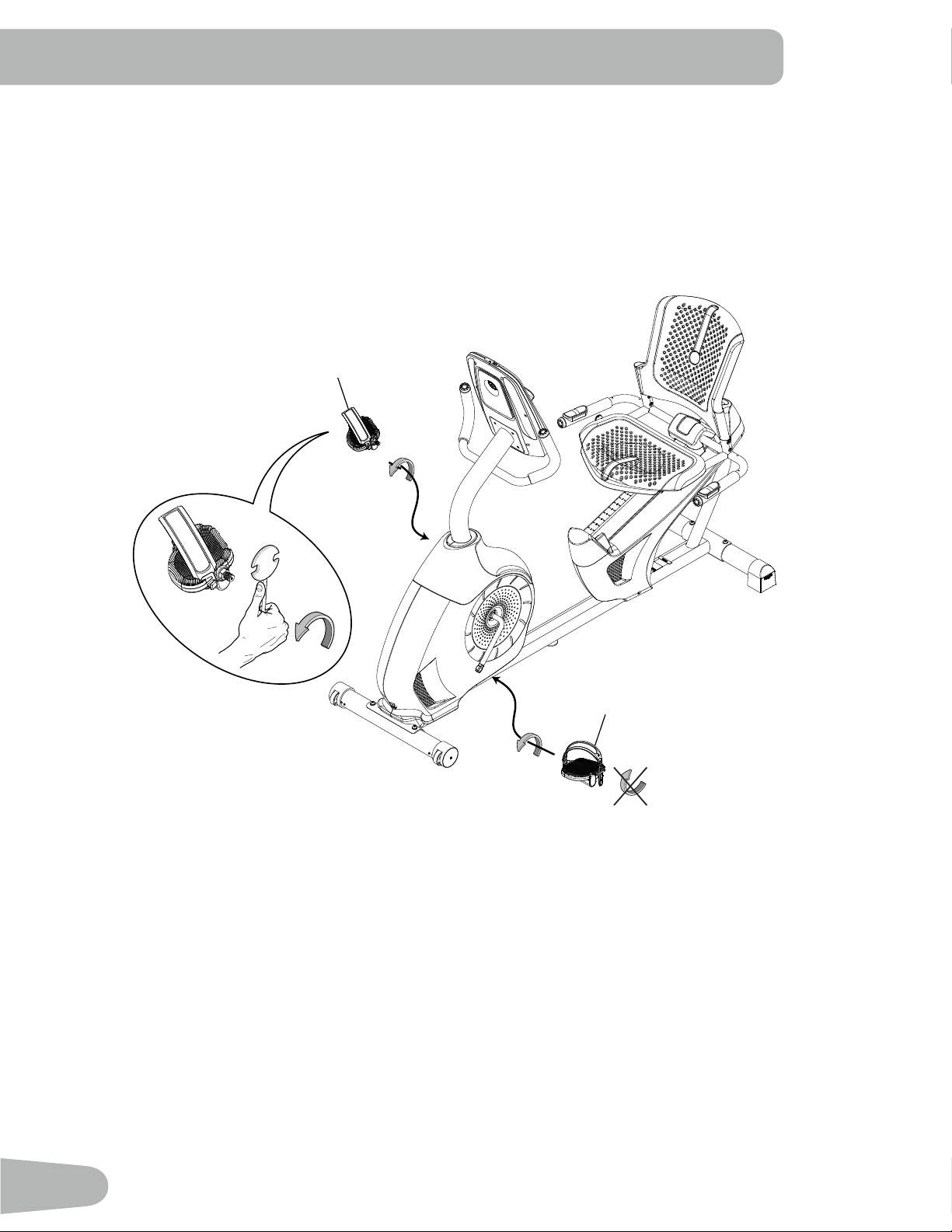
9. Attach Pedals to Frame Assembly
NOTICE: The Left Pedal is reverse-threaded. Be sure to attach Pedals on the proper side of the Bike. Orientation
is based from a seated position on the bike. The Left Pedal has an “L”, the Right Pedal an “R”.
13
11
17
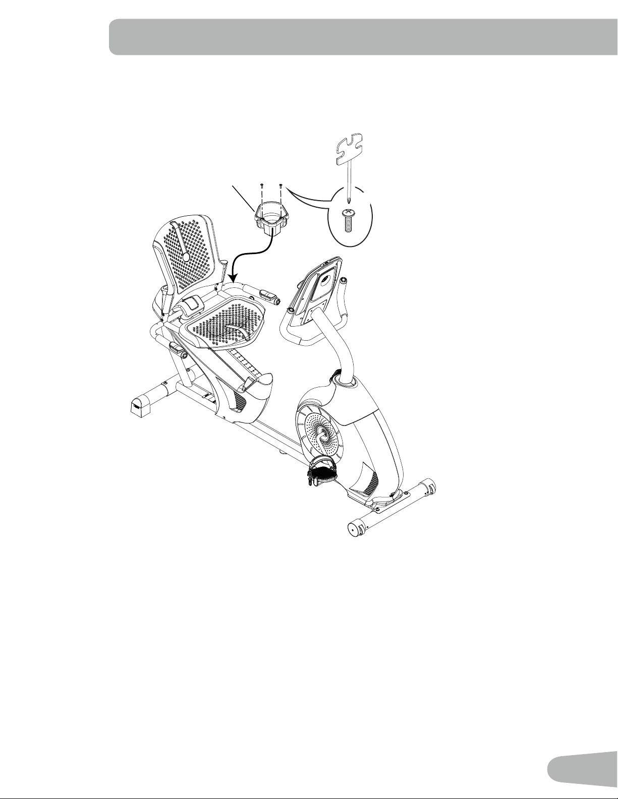
10. Attach Water Bottle Holder to Frame Assembly
2
X2
F
#2
18
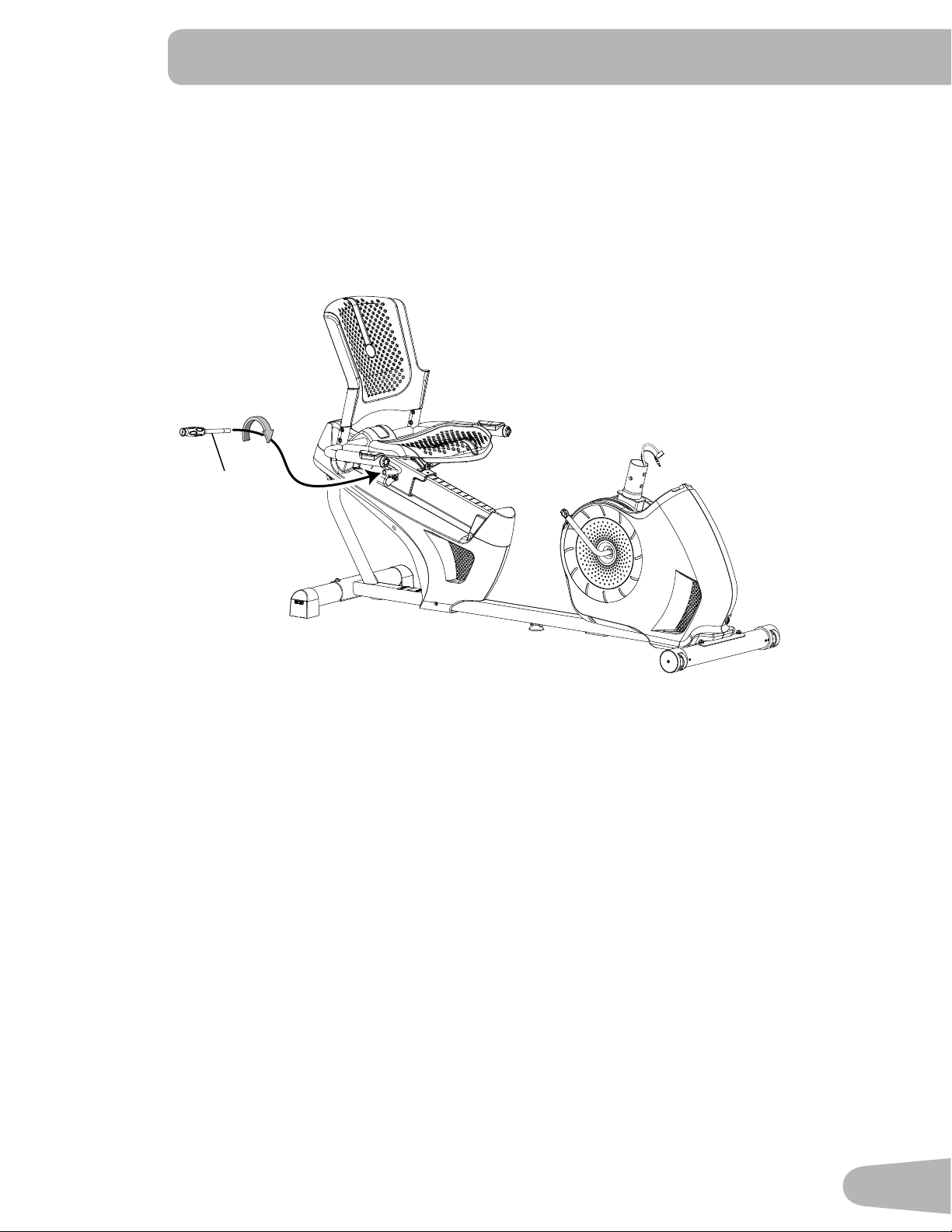
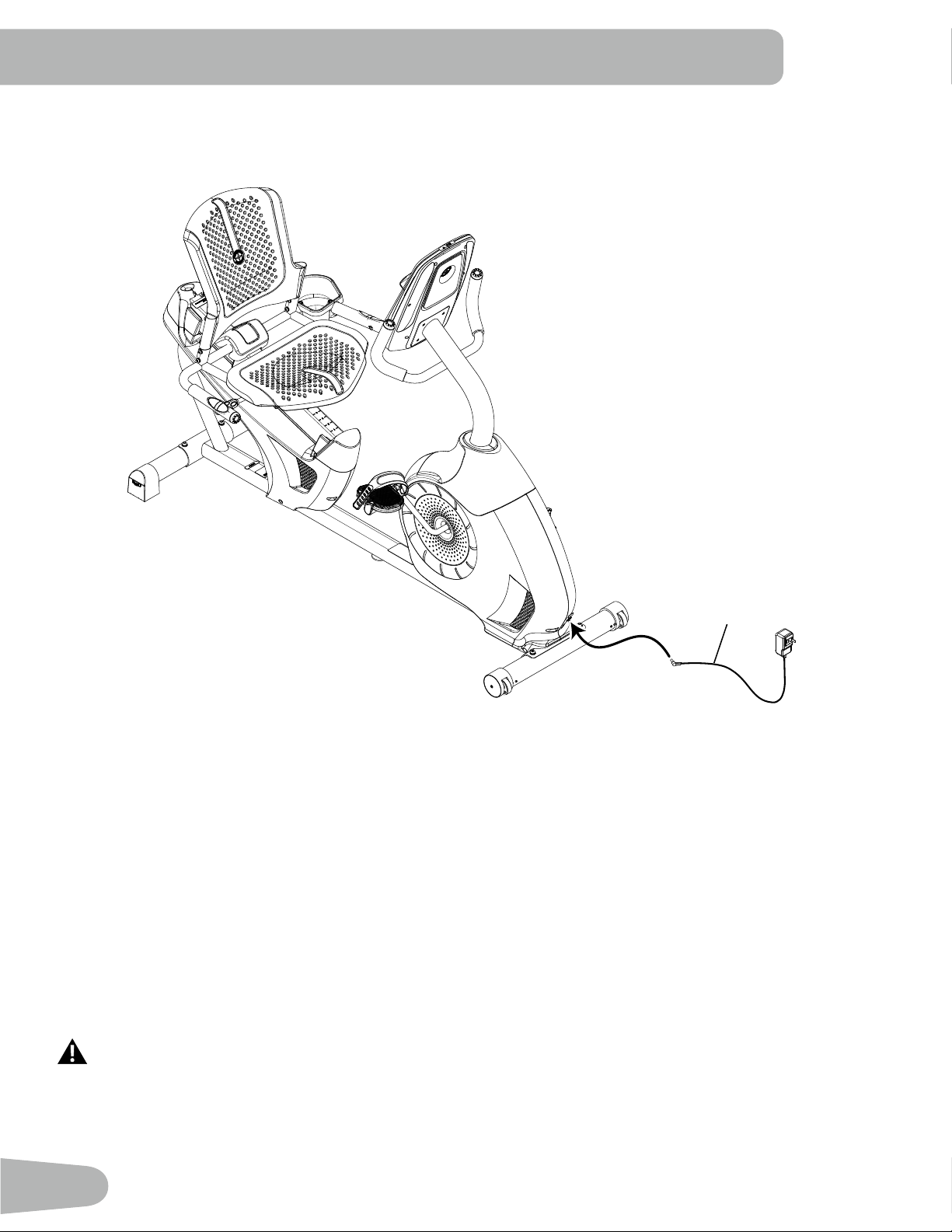
11. Connect AC Adapter to Frame Assembly
12. Final Inspection
Inspect your machine to ensure that all hardware is tight and components are properly assembled.
Be sure to record the serial number in the field provided at the front of this manual.
Do not use until the machine has been fully assembled and inspected for correct performance in
accordance with the Owner’s Manual.
10
19
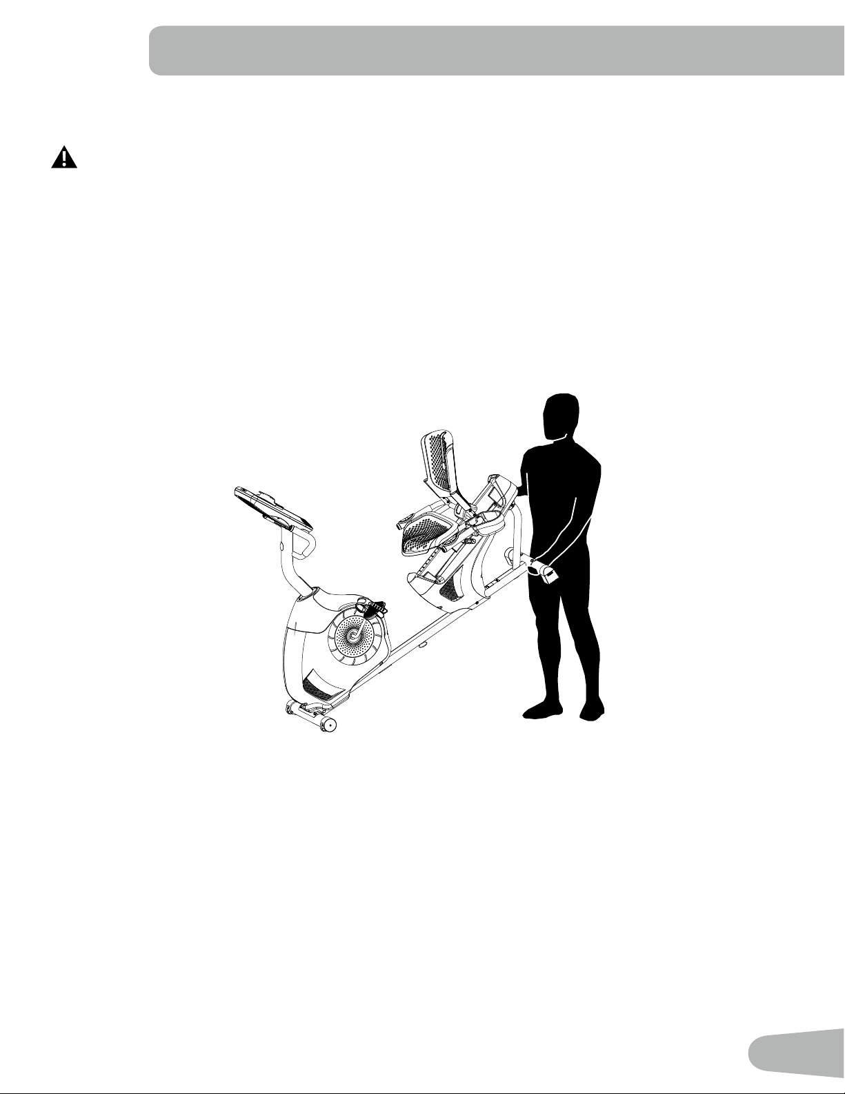
Moving the Bike
The machine may be moved by one or more persons depending on their physical abilities and capacities.
Make sure that you and others are all physically fit and able to move the machine safely.
1. Remove the power cord.
2. Use the Transport Handle to carefully lift the machine onto the transport rollers.
3. Push the machine into position.
4. Carefully lower the machine into position.
NOTICE: Be careful when you move the bike. All abrupt motions can affect the computer operation.
BEFORE YOU START
20
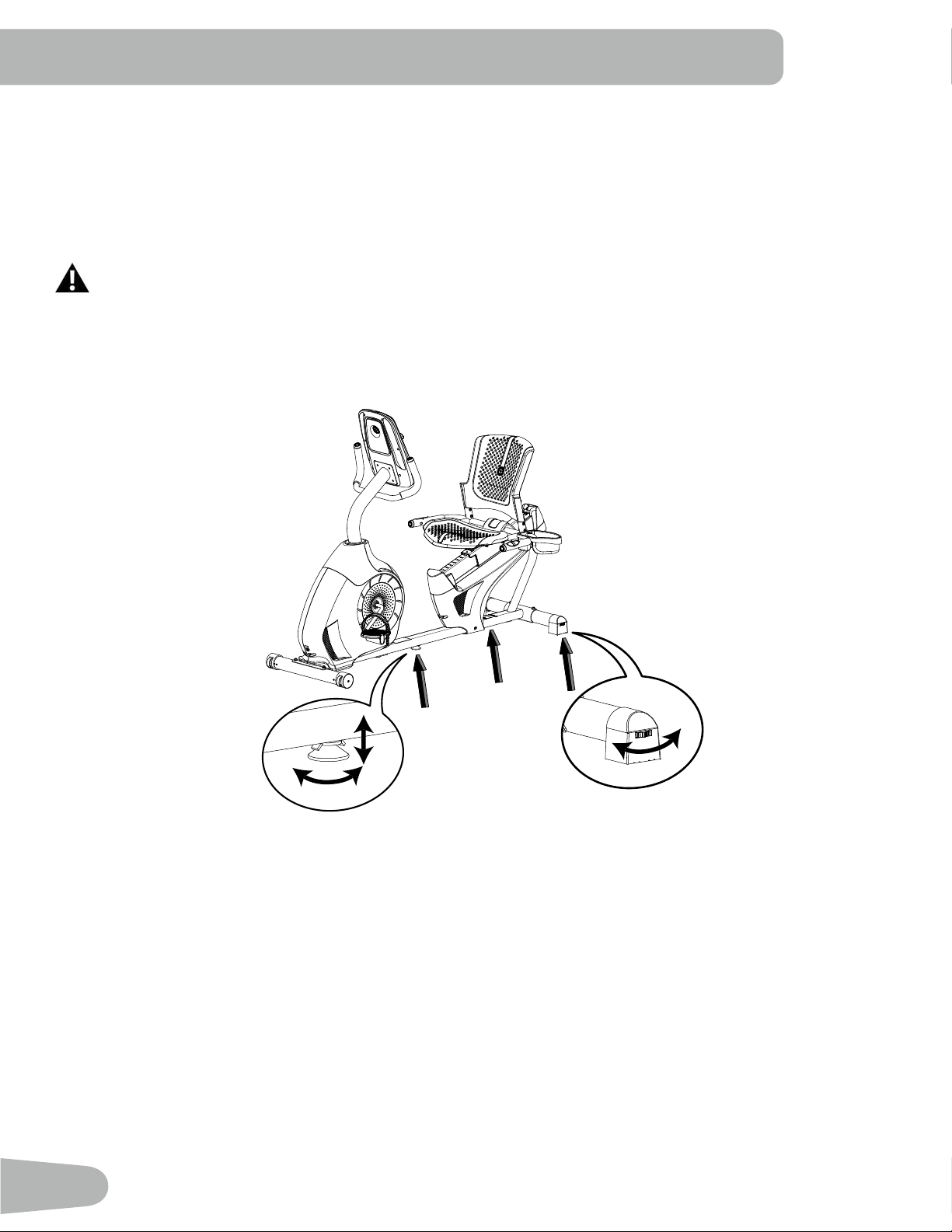
Leveling the Bike
Levelers are found on each side of the Rear Stabilizer and on the Frame Rail. On the Rear Stabilizer, turn the knob to
adjust the stabilizer foot.
To adjust the leveler on the Frame Rail:
1. Loosen the upper locking nut.
2. Turn the leveler to adjust the height.
Do not adjust the levelers to such a height that they detach or unscrew from the machine. Injury to you or
damage to the machine can occur.
3. Tighten the upper locking nut to lock the leveler.
Make sure the bike is level and stable before you exercise.
21
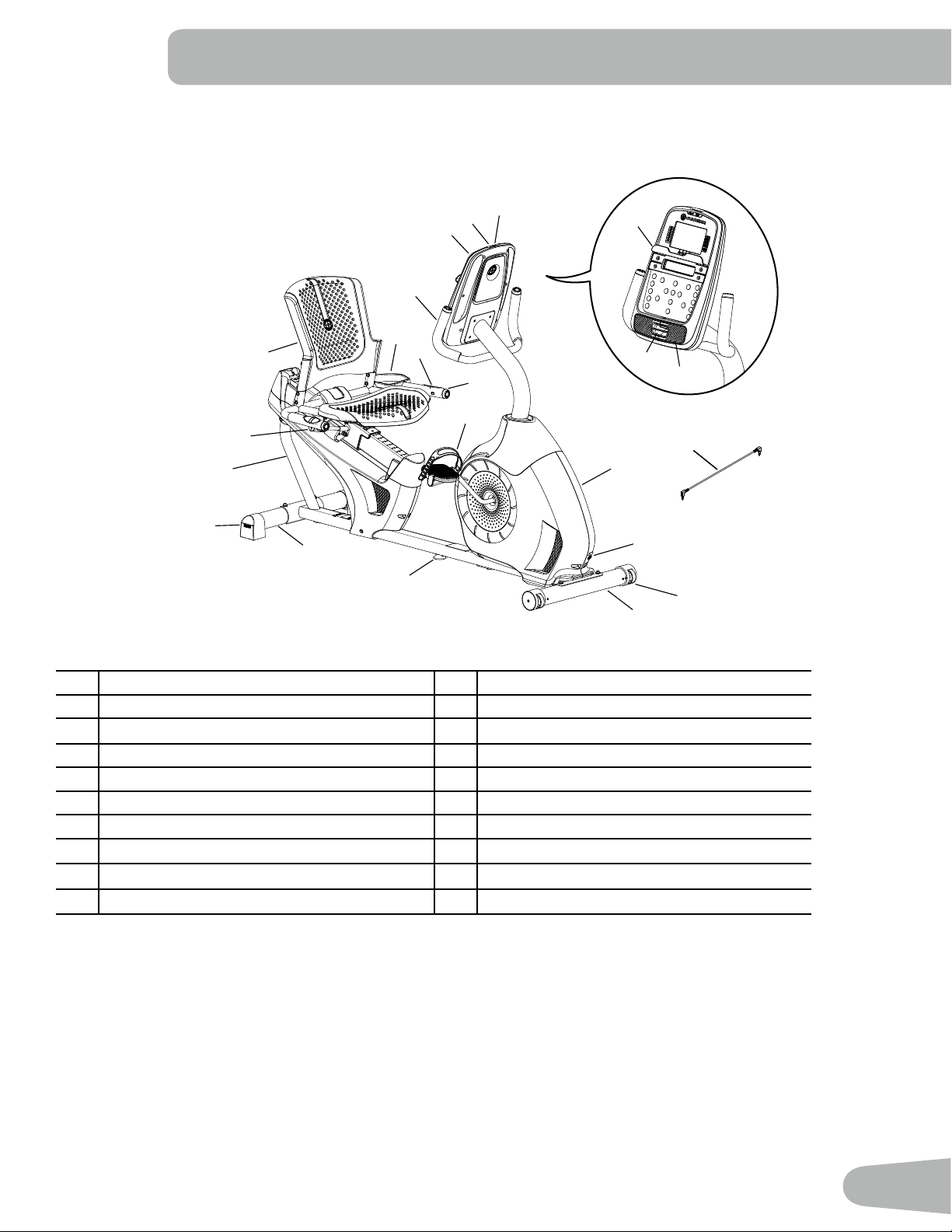
FEATURES
B
C
A
H
I
G
J
K
P
R
L
K
J
M
N
Q
O
E
F
D
S
T
A Console K Leveler
B MP3 Input L Transport Handle
C USB Port M Seat Adjustment Knob
D Media Tray N Water Bottle Holder
E Fan O Adjustable Seat
F Speakers P Contact Heart Rate (CHR) Sensors
G Fully Shrouded Flywheel Q Handlebar, Side
H Power Connector R Pedal
I Transport Wheel S Handlebar, Upright
J Stabilizer T Media Cable
WARNING! Use the values calculated or measured by the machine’s computer for reference purposes only. The
heart rate displayed is an approximation and should be used for reference only. Over exercising may
result in serious injury or death. If you feel faint stop exercising immediately.
22
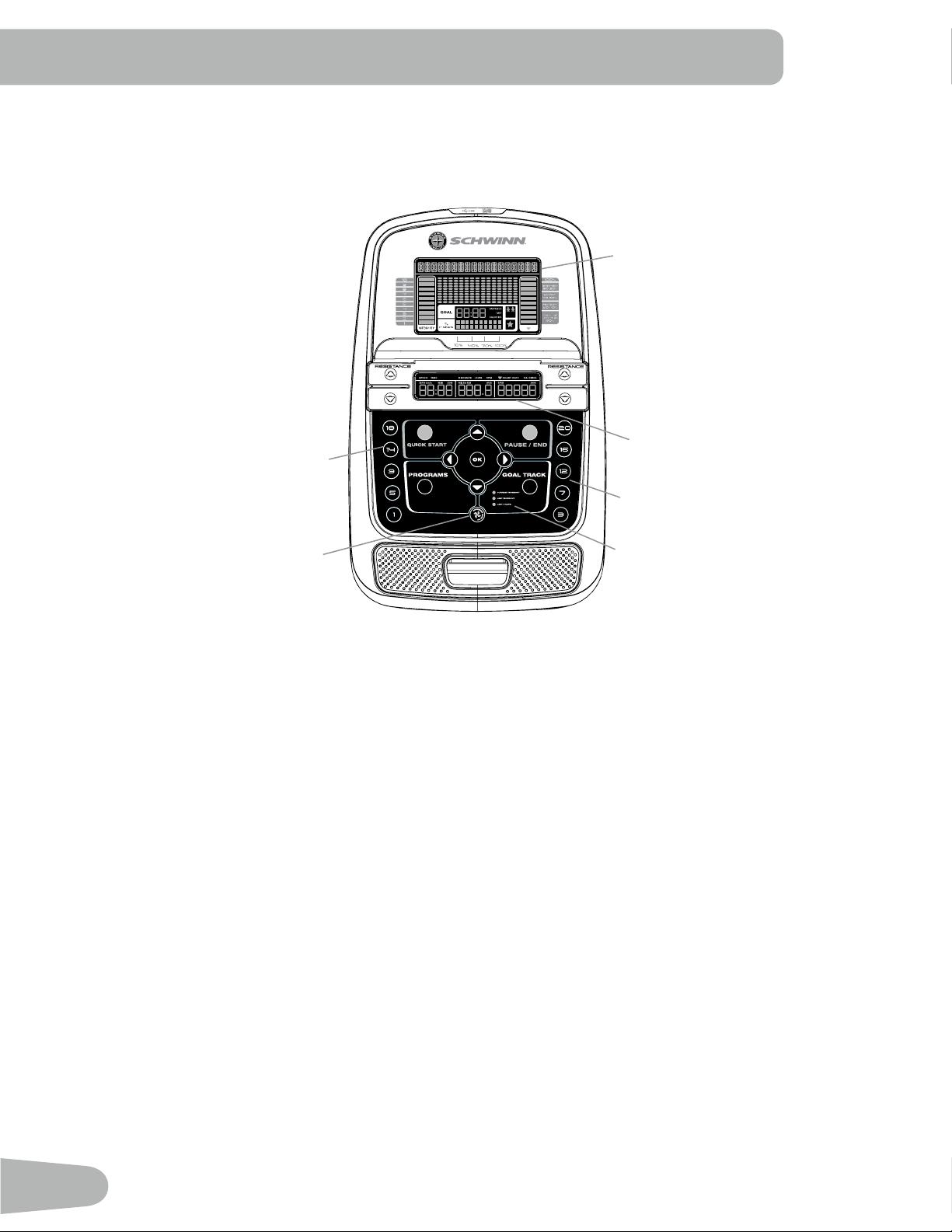
Console Features
The Console provides important information about your workout and lets you control the resistance levels while you
exercise. The Console features the Schwinn Dual Track
™
display with touch control buttons to navigate you through the
exercise programs.
Keypad Functions
Resistance Increase () button- Increases the workout resistance level
Resistance Decrease () button- Decreases the workout resistance level
QUICK START button- Begins a Quick Start workout
PROGRAMS button- Selects a category and workout program
PAUSE / END button- Pauses an active workout, ends a paused workout, or goes back to the previous screen
GOAL TRACK button-Displays the Workout Totals and Achievements for the selected User Prole
Increase () button- Increases a value (age, time, distance, or calories) or moves through options
Left () button- Displays different workout values during a workout, and moves through options
OK button- Starts a Program workout, conrms information, or resumes a paused workout.
Right () button- Displays different workout values during a workout, and moves through options
Decrease () button- Decreases a value (age, time, distance, or calories) or moves through options
FAN button- Controls 3-speed fan
10%
40%
70%
1
2
3
4
5
6
7
8
9
10
Hr
Hr
Upper Display
Lower Display
Resistance Level Quick Buttons
Resistance Level Quick Buttons
Achievement Indicator Lights
Fan
23
Resistance Level Quick Buttons- Shifts the resistance levels to the setting quickly during a workout
Achievement Indicator Lights- when a workout result is reviewed, the achievement indicator light will activate.
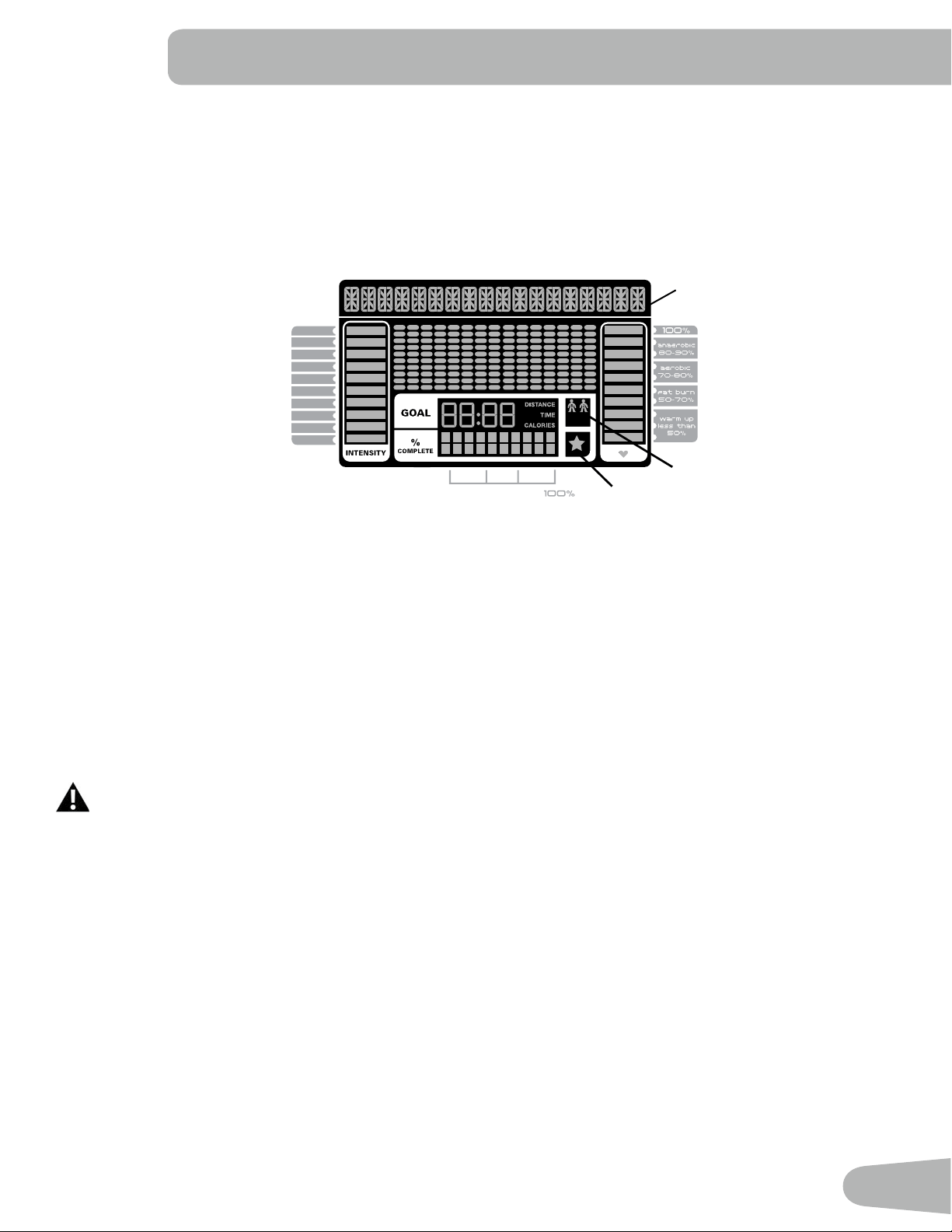
Schwinn Dual Track™ Display
Upper Display Data
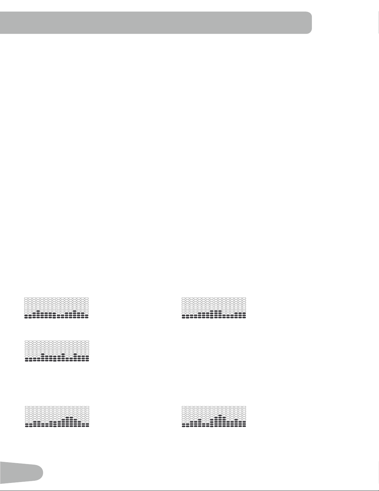
Program Display
The Program Display shows information to the User and the grid display area shows the course prole for the program.
Each column in the prole shows one interval (workout segment). The higher the column, the higher the resistance level.
The ashing column shows your current interval.
Intensity Display
The Intensity Display shows the level of work at that moment based on the current resistance level.
Heart Rate Zone Display
The Heart Rate Zone shows which zone the current heart rate value falls into for the current User. These Heart Rate
Zones can be used as a workout guide for a certain target zone (anaerobic, aerobic, or fat burn).
Consult a physician before you start an exercise program. Stop exercising if you feel pain or tightness in
your chest, become short of breath, or feel faint. Contact your doctor before you use the machine again.
The heart rate displayed is an approximation and should be used for reference only.
Note: If no heart rate is detected, the display will be blank.
Goal Display
The Goal Display shows the currently selected type of goal (Distance, Time or Calories), the current value to achieve the
goal, and the percent completed toward the goal.
User Display
The User Display shows which User Prole is currently selected.
Achievement Display
The Achievement Display activates when a workout goal is reached or a workout milestone is surpassed from past
workouts. The Console display will congratulate and inform the User of their achievement, along with a celebratory sound.
Program Display
10%
40%
70%
1
2
3
4
5
6
7
8
9
10
Hr
Hr
User Display
Achievement Display

24
Lower Display Data
The Lower Display shows the Workout Values and can be customized for each User (Consult the “Edit User Prole”
section of this manual). Use the Right() button to move through all the workout statistics.
Speed
The Speed display eld shows the machine speed in miles per hour (mph) or kilometers per hour (km/h).
Time
The TIME display eld shows the total time count of the workout, the average Time for the User Prole, or the total opera-
tional time of the machine.
Note: If a Quick Start workout is performed for more than 99 minutes and 59 seconds (99:59), the units for Time will shift
to hours and minutes ( 1 hour, 40 minutes ).
Distance
The Distance display shows the distance count (miles or km) in the workout.
Note: To change the measurement units to English Imperial or metric, refer to the “Console Setup Mode” section in this
manual.
Level
The LEVEL display shows the current resistance level in the workout.
RPM
The RPM display eld shows the pedal revolutions per minute (RPM).
Heart Rate (Pulse)
The Heart Rate display shows the beats per minute (BPM) from the heart rate monitor. When a heart rate signal is re-
ceived by the Console, the icon will ash.
Consult a physician before you start an exercise program. Stop exercising if you feel pain or tightness in
your chest, become short of breath, or feel faint. Contact your doctor before you use the machine again.
The heart rate displayed is an approximation and should be used for reference only.
Calories
The Calories display eld shows the estimated calories that you have burned during the exercise.
OK
PAUSE/
END
QUICK
START
PROGRAMS
GOAL TRACK
CURRENT WORKOUT
LAST WORKOUT
LAST 7 DAYS
1
5
9
14
18
3
7
12
16
20
10%
40%
70%
1
2
3
4
5
6
7
8
9
10
Hr
10%
40%
70%
1
2
3
4
5
6
7
8
9
10
Hr

25
Export Workout Results to USB Flash Drive
This tness machine is equipped with a USB Port and can export your Workout Results to a USB Flash Drive. With the
Workouts exported from the tness machine, connect the USB Flash Drive to a computer and upload the le to your Sch-
winn Connect™ account.
Note: USB Flash Drives must be formatted in FAT32 for proper functionality.
1. From the Power-Up screen, push the User button to select the desired User Prole.
2. Insert the USB Flash Drive into the USB Port on the Console.
3. The Console will display “SAVING TO USB”, and then “DO NOT REMOVE”. The current User Prole will begin to
ash, showing the Workout Results are being exported to the USB Flash Drive. Do not remove the USB Flash Drive
until the User Prole does not ash and the Console displays “REMOVE USB”.
Note: If the Workout Results on the USB Flash Drive are current, the Console will not export the le again. As more
workouts are completed, the Console will take longer to export all of the Workout Results. For longer exports, the
Console will display an export status count ( exported workouts / total number of workouts ).
4. When the export is complete the User Prole will stop ashing, the Console will display “USB COMPLETE”, followed
by the “REMOVE USB” prompt. It is now safe to remove the USB Flash Drive.
5. The Console will display the Power-Up Mode screen.
If a Workout is completed with a USB Flash Drive already inserted, the Console will not export the new Workout Results
until the Console exits the Results mode and displays the Power-Up Mode screen.
Track Your Results at www.schwinnconnect.com
Take advantage of the Schwinn Connect™ website to see your progress over time and share your data with MyFitness-
Pal
®
. Review your workouts and results away from the machine when convenient for you. The Schwinn Connect™ web-
site allows for a workout value to be selected and have it graphed for weekly, monthly, or yearly comparison review.
If using a USB Flash Drive to import workout results to the Schwinn Connect™ website:
1. Insert the USB Flash Drive with your workout data into a device connected to the internet.
2. Sign in to the Schwinn Connect™ website at www.schwinnconnect.com.
3. Click the Upload button on the web site.
4. In the Upload File window, locate your USB Flash Drive. Select the workout data le from it, and click the upload
button. Your workout data will upload into your account.
Note: The name of the data le will either be the selected User (“ USER1.DAT “) or the name of the customized User
(example- “ JOHN.DAT “), followed by the .DAT le format.
5. To sync your workout data with MyFitnessPal
®
, select the Menu option in the upper left corner of the web page and
select the “Sync to MyFitnessPal
®
“ option.
Note: The Schwinn Connect™ software will automatically sync your workouts with MyFitnessPal
®
after the initial
syncing.
Contact Heart Rate Sensors
Contact Heart Rate (CHR) sensors send your heart rate signals to the Console. The CHR sensors are the stainless steel
parts of the Handlebars. To use, put your hands comfortably around the sensors. Be sure that your hands touch both the
top and the bottom of the sensors. Hold rm, but not too tight or loose. Both hands must make contact with the sensors for
the Console to detect a pulse. After the Console detects four stable pulse signals, your initial pulse rate will be shown.
Once the Console has your initial heart rate, do not move or shift your hands for 10 to 15 seconds. The Console will now
validate the heart rate. Many factors inuence the ability of the sensors to detect your heart rate signal:
26
• Movement of the upper body muscles (including arms) produces an electrical signal (muscle artifact) that can interfere
with pulse detection. Slight hand movement while in contact with the sensors can also produce interference.
• Calluses and hand lotion may act as an insulating layer to reduce the signal strength.
• Some Electrocardiogram (EKG) signals generated by individuals are not strong enough to be detected by the sensors.
• The proximity of other electronic machines can generate interference.
If your heart rate signal ever seems erratic after validation, wipe off your hands and the sensors and try again.
Heart Rate Calculations
Your maximum heart rate usually decreases from 220 Beats Per Minute (BPM) in childhood to approximately 160 BPM by
age 60. This fall in heart rate is usually linear, decreasing by approximately one BPM for each year. There is no indication
that training inuences the decrease in maximum heart rate. Individuals of the same age could have different maximum
heart rates. It is more accurate to nd this value by completing a stress test than by using an age related formula.
Your at-rest heart rate is inuenced by endurance training. The typical adult has an at rest heart rate of approximately 72
BPM, whereas highly trained runners may have readings of 40 BPM or lower.
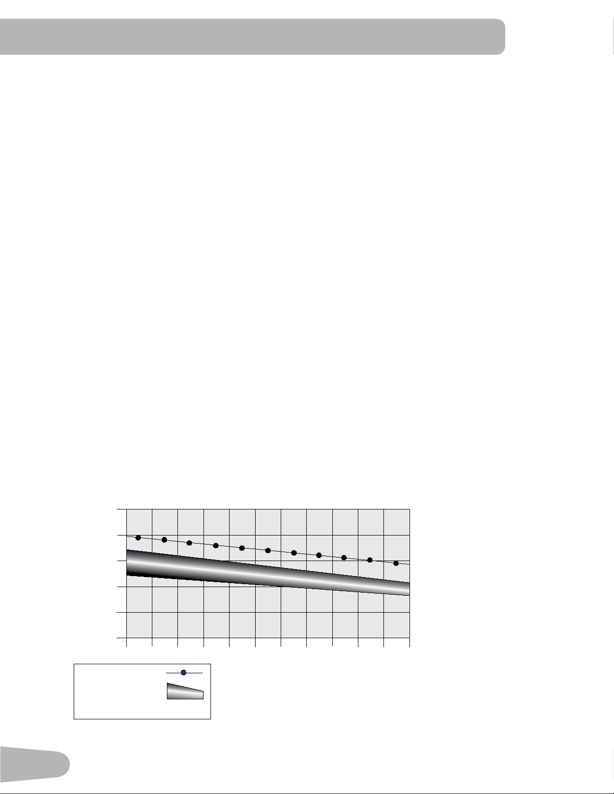
The Heart Rate table is an estimate of what Heart Rate Zone (HRZ) is effective to burn fat and improve your cardiovas-
cular system. Physical conditions vary, therefore your individual HRZ could be several beats higher or lower than what is
shown.
The most efcient procedure to burn fat during exercise is to start at a slow pace and gradually increase your intensity un-
til your heart rate reaches between 60 – 85% of your maximum heart rate. Continue at that pace, keeping your heart rate
in that target zone for over 20 minutes. The longer you maintain your target heart rate, the more fat your body will burn.
The graph is a brief guideline, describing the generally suggested target heart rates based on age. As noted above, your
optimal target rate may be higher or lower. Consult your physician for your individual target heart rate zone.
Note: As with all exercises and tness regimens, always use your best judgment when you increase your exercise time
or intensity.
20-24
FAT-BURNING TARGET HEART RATE
Heart Rate BPM (beats per minute)
Age
25-29
0
50
100
150
200
250
30-34 35-39 40-44 45-49 50-54 55-59 60-64 65-69 70+
196
191
186
181
176
171
166
161
156
151
146
167
162
158
154
150
145
141
137
133
128
126
Maximum Heart Rate
Target Heart Rate Zone
(keep within this range
for optimum fat-burning)
11 8
11 5
11 2
109
106
103
100
97
94
91
88
27
OPERATIONS
What to Wear
Wear rubber-soled athletic shoes. You will need the appropriate clothes for exercise that allow you to move freely.
How Often Should You Exercise
Consult a physician before you start an exercise program. Stop exercising if you feel pain or tightness in
your chest, become short of breath, or feel faint. Contact your doctor before you use the machine again.
Use the values calculated or measured by the machine’s computer for reference purposes only. The heart
rate displayed on the console is an approximation and should be used for reference only.
• 3 times a week for 30 minutes each day.
• Schedule workouts in advance and try to follow the schedule.
Seat Adjustment
Correct seat placement encourages exercise efciency and comfort, while reducing the risk of
injury.
1. With a Pedal in the forward position, place the ball of your foot over the center of it. Your leg
should be bent slightly at the knee.
2. If your leg is too straight or your foot cannot touch the Pedal, move the seat forward. If your
leg is bent too much, move the seat toward the back.
Step off the bike before you adjust the seat.
3. Push down on the Seat Adjustment Handle, and adjust the seat to the desired height.
4. Pull up the Seat Adjustment Handle to engage the locking mechanism. Be sure that the
handle is fully engaged.
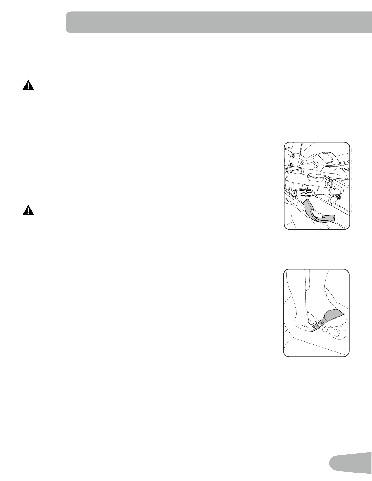
Foot Position / Pedal Strap Adjustment
Foot pedals with straps provide secure footing to the exercise bike.
1. Rotate the Pedals until one can be reached.
2. Put the ball of each foot on the Pedals.
3. Fasten the strap over the shoe.
4. Repeat for the other foot.
Be sure toes and knees point directly forward to ensure maximum Pedal efciency. Pedal straps
can be left in position for subsequent workouts.
Power-Up / Idle Mode
The Console will enter Power-Up / Idle Mode if it is plugged into a power source, any button is pushed, or if it receives a
signal from the RPM sensor as a result of pedaling the machine.
Auto Shut-Off (Sleep Mode)
If the Console does not receive any input in approximately 5 minutes, it will automatically shut off. The LCD display is off
while in Sleep Mode.
Note: The Console does not have an On/Off switch.

28
Initial Setup
During the rst power-up, the Console should be setup with the date, time and your preferred measurement units.
1. Date: Push the Increase/Decrease buttons to adjust the currently active value (ashing). Push the Left/Right buttons
to change which segment is the currently active value (month / day / year).
2. Push OK to set.
3. Time: Push the Increase/Decrease buttons to adjust the currently active value (ashing). Push the Left/Right buttons
to change which segment is the currently active value (hour / minute / AM or PM).
4. Push OK to set.
5. Units of Measurement: Push the Increase/Decrease buttons to adjust between “MILES” (Imperial English) or “KM”
(metric).
6. Push OK to set. The Console goes back to the Power-Up / Idle Mode screen.
Note: To adjust these selections, consult the “Console Set-Up Mode” section.
Quick Start ( Manual ) Program
The Quick Start ( Manual ) program lets you start a workout without entering any information.
During a Manual Workout, each column represents a 2 minute time period. The active column will advance across the
screen every 2 minutes. If the workout lasts for more than 30 minutes, the active column is xed on the farthest column on
the right and pushes the previous columns off the display.
1. Sit on the machine.
2. Push the Increase/Decrease button to select the correct User prole. If you do not have a User prole set up, you can
select a User prole that has no customized data (default values only).
3. Push the QUICK START button to start the Manual program.
4. To change the resistance level, push the Resistance Increase/Decrease buttons. The current interval and future
intervals are set to the new level. The default Manual resistance level is 4. The time will count up from 00:00.
Note: If a Manual workout is performed for more than 99 minutes and 59 seconds (99:59), the units for Time will shift to
hours and minutes ( 1 hour, 40 minutes ).
5. When done with your workout, stop pedaling and push PAUSE/END to pause the workout. Push PAUSE/END again
to end the workout.
Note: The workout results are recorded to the current User Profile.
User Profiles
The Console lets you store and use 2 User profiles. The User profiles automatically record the workout results for each
workout, and allow the workout data to be reviewed.
The User profile stores the following data:
• Name—up to 10 characters
• Age
• Weight
• Height
• Gender
• Preferred Workout Values

29
Select a User Profile
Every workout is saved to a User Prole. Be sure to select the proper User Prole before starting a workout. The last User
that completed a workout will be the default user.
User Proles are assigned the default values until they are customized by editing. Be sure to edit the User Prole for more
accurate calorie and heart rate information.
From the Power-Up Mode screen, push the Increase() or Decrease() buttons to select one of the User Proles. The
Console will display the name of the User Prole and the User Prole Icon.
Edit User Profile
1. From the Power-Up Mode screen, push the Increase() or Decrease() buttons to select one of the User Proles.
2. Push the OK button to select the User Profile.
3. The Console display shows the EDIT prompt and the current User Profile name. Push OK to start the Edit User Prole
option.
To exit the Edit User Prole option, push the PAUSE/END button and the console will go back to the Power-Up Mode
screen.
4. The Console display shows the NAME prompt and the current User Profile name.
Note: The User name will be blank if this is the first edit. The name of a User Profile is limited to 10 characters.
The currently active segment will flash. Use the Increase/Decrease buttons to move through the alphabet and blank
space (found between A and Z). To set each segment, use the Left() or Right() buttons to shift between segments.
Push the OK button to accept the displayed User name.
5. To edit the other User data (EDIT AGE, EDIT WEIGHT, EDIT HEIGHT, EDIT GENDER), use the Increase/Decrease
buttons to adjust, and push OK to set each entry.
6. The Console display shows the SCAN prompt. This option controls how the workout values are displayed in the Lower
Display during a workout. The “OFF” setting allows the user to push the RIGHT or LEFT buttons to view the other
workout value channels when desired. The “ON” setting allows the Console to automatically display the workout value
channels every 6 seconds.
The default is “OFF”.
Push the OK button to set how the workout values are displayed.
7. The Console display shows the EDIT LOWER DISPLAY prompt. This option allows you to customize which Workout
Values are displayed during a workout.
The Lower Display will show all of the workout values, with the active Workout Value ashing. The Upper Display
shows the active value setting: “ON” or “OFF”. Push the Increase() or Decrease() buttons to hide the active
workout value, and push the Left() or Right() buttons to shift the active workout value.
NOTE: to show a hidden workout value, repeat procedure and change Upper Display value to “ON” for that value.
When done with customizing the Lower Display, push the OK button to set it.
Hr
8. The Console will go to the Power-Up Mode screen with the user selected.
30
Reset a User Profile
1. From the Power-Up Mode screen, push the Increase() or Decrease() buttons to select one of the User Proles.
2. Push the OK button to select the User Profile.
3. The Console display shows the current User Profile name and the EDIT prompt. Push the Increase() or Decrease()
buttons to change the prompt.
Note: To exit the Edit User Prole option, push the PAUSE/END button and the console will go back to the Power-Up
Mode screen.
4. The Console display shows the RESET prompt and the current User Profile name. Push OK to start the Reset User
Prole option.
5. The Console will now confirm the request to reset the User profile (the default selection is ‘NO’). Push the Increase()
or Decrease() buttons to adjust the selection.
6. Push OK to make your selection.
7. The Console will go to the Power-Up Mode screen.
Changing Resistance Levels
Push the Resistance Level Increase() or Decrease() buttons to change the resistance level at any time in a workout
program. To rapidly change the resistance level, push the desired Resistance Level Quick Button. The Console will adjust
to the selected resistance level of the quick button.
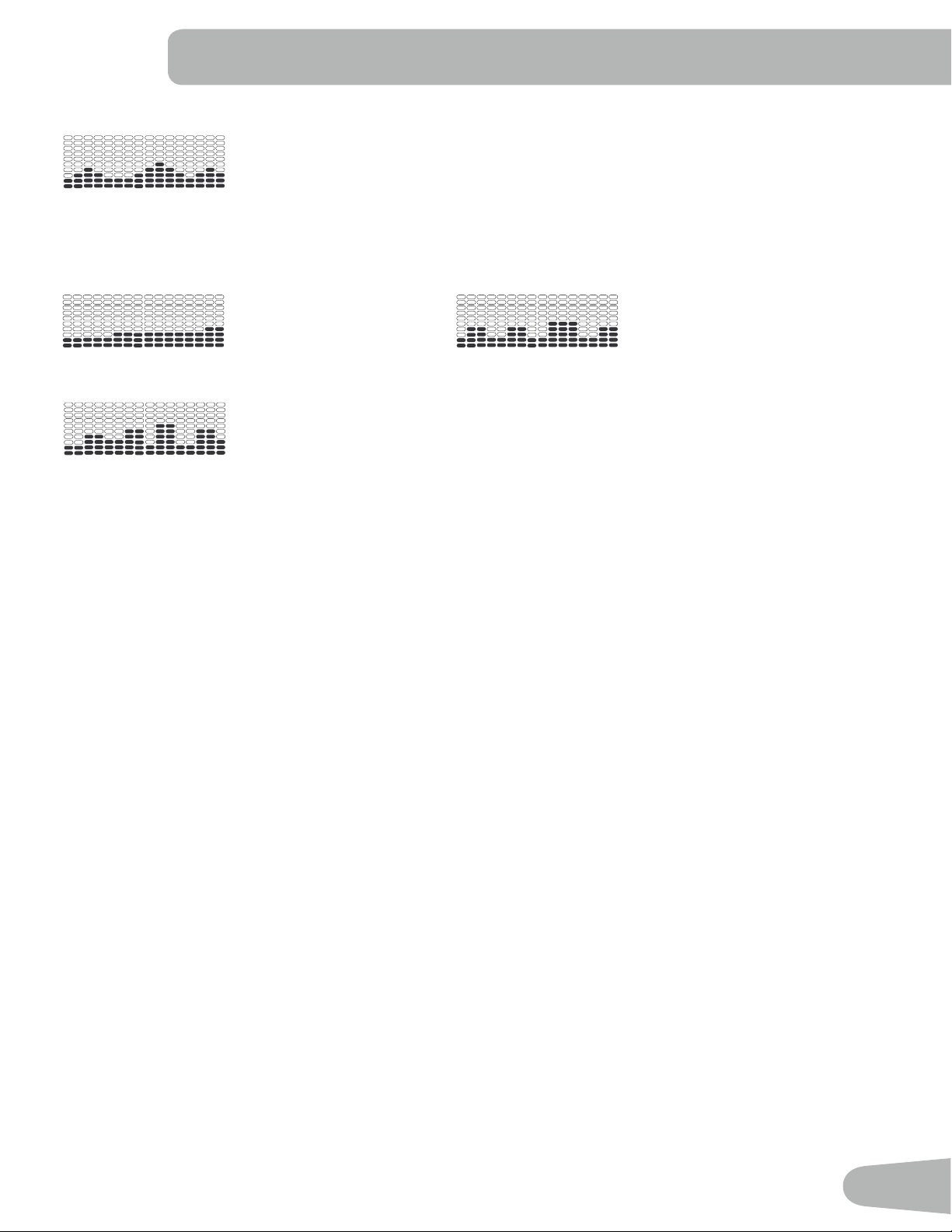
Profile Programs
These programs automate different resistance and workout levels. The Prole Programs are organized into Categories
(Fun Rides, Mountains, and Challenges).
Note: Once a User views all the Categories, they will be expanded to display the Programs within each of the Cat-
egories.
FUN RIDES
Rolling Hills Ride in the Park
Secondary Case 6: Profile Programs
Rolling Hills
FUN RIDES
Ride in the Park Easy Tour
Pike’s Peak
MOUNTAINS
Mount Hood Pyramids
Uphill Finish
CHALLENGES
Cross-Training Interval
Stream Crossing
Summit Pass
Stairs
REVED : 122612
Secondary Case 6: Profile Programs
Rolling Hills
FUN RIDES
Ride in the Park Easy Tour
Pike’s Peak
MOUNTAINS
Mount Hood Pyramids
Uphill Finish
CHALLENGES
Cross-Training Interval
Stream Crossing
Summit Pass
Stairs
REVED : 122612
Easy Tour
Secondary Case 6: Profile Programs
Rolling Hills
FUN RIDES
Ride in the Park Easy Tour
Pike’s Peak
MOUNTAINS
Mount Hood Pyramids
Uphill Finish
CHALLENGES
Cross-Training Interval
Stream Crossing
Summit Pass
Stairs
REVED : 122612
MOUNTAINS
Pike’s Peak Mount Hood
Secondary Case 6: Profile Programs
Rolling Hills
FUN RIDES
Ride in the Park Easy Tour
Pike’s Peak
MOUNTAINS
Mount Hood Pyramids
Uphill Finish
CHALLENGES
Cross-Training Interval
Stream Crossing
Summit Pass
Stairs
REVED : 122612
Secondary Case 6: Profile Programs
Rolling Hills
FUN RIDES
Ride in the Park Easy Tour
Pike’s Peak
MOUNTAINS
Mount Hood Pyramids
Uphill Finish
CHALLENGES
Cross-Training Interval
Stream Crossing
Summit Pass
Stairs
REVED : 122612
31
Pyramids
Secondary Case 6: Profile Programs
Rolling Hills
FUN RIDES
Ride in the Park Easy Tour
Pike’s Peak
MOUNTAINS
Mount Hood Pyramids
Uphill Finish
CHALLENGES
Cross-Training Interval
Stream Crossing
Summit Pass
Stairs
REVED : 122612
CHALLENGES
Uphill Finish Cross-Training
Secondary Case 6: Profile Programs
Rolling Hills
FUN RIDES
Ride in the Park Easy Tour
Pike’s Peak
MOUNTAINS
Mount Hood Pyramids
Uphill Finish
CHALLENGES
Cross-Training Interval
Stream Crossing
Summit Pass
Stairs
REVED : 122612
Secondary Case 6: Profile Programs
Rolling Hills
FUN RIDES
Ride in the Park Easy Tour
Pike’s Peak
MOUNTAINS
Mount Hood Pyramids
Uphill Finish
CHALLENGES
Cross-Training Interval
Stream Crossing
Summit Pass
Stairs
REVED : 122612
Interval
Secondary Case 6: Profile Programs
Rolling Hills
FUN RIDES
Ride in the Park Easy Tour
Pike’s Peak
MOUNTAINS
Mount Hood Pyramids
Uphill Finish
CHALLENGES
Cross-Training Interval
Stream Crossing
Summit Pass
Stairs
REVED : 122612
Workout Profile and Goal Program
The Console lets you select the Prole Program and type of Goal for your workout (Distance, Time or Calories), and set
the Goal value.
1. Sit on the machine.
2. Push the Increase() or Decrease() buttons to select the correct User prole.
3. Push the Programs button.
4. Push the Left() or Right() buttons to select a Category of Workout.
5. Push the Increase() or Decrease() buttons to select a Profile Workout, and push OK.
6. Use the Increase() or Decrease() buttons to select a type of Goal (Distance, Time or Calories), and push OK.
7. Use the Increase() or Decrease() buttons to adjust the workout value.
8. Push OK to begin the goal-oriented workout. The GOAL value will count down as the value for percent completed
increases.
Note: During a Calories Goal, each column is for a 2 minute time period. The active column will advance across the
screen every 2 minutes. If the workout lasts for more than 30 minutes, the active column will x to the last right
column and push the previous columns off the display.
Fitness Test Program
The Fitness Test measures the improvements of your physical tness level. The test compares your power output (in
Watts) to your heart rate. As your tness level improves, your power output will increase at a given heart rate.
Note: The Console must be able to read the heart rate information from the Contact Heart Rate (CHR) sensors to work
correctly.
You can start the Fitness Test from the FEEDBACK category. The Fitness Test program rst prompts you to select your
tness level—Beginner ( “BEG” ) or Advanced ( “ADV” ). The Console will use the Age and Weight values for the selected
User Prole to calculate the Fitness Score.
Start to workout and hold the Heart Rate Sensors. When the test starts, the intensity of the workout slowly increases. This
means you will work harder, and as a result, your heart rate increases. The intensity continues to increase automatically

32
until your heart rate reaches the “Test Zone”. This zone is individually computed to be near 75 percent of the maximum
heart rate of your User Prole. When you reach the Test Zone, the machine holds the intensity steady for 3 minutes.
This lets you reach a stable condition (where your heart rate becomes steady). At the end of the 3 minutes, the Console
measures your heart rate and the power output. These numbers, along with information about your age and weight, are
computed to produce a “Fitness Score”.
Note: Fitness Test scores should only be compared to your previous scores and not to other User Profiles.
Compare your Fitness Scores to see your improvement.
Heart Rate Control (HRC) Workout Programs
The Heart Rate Control (HRC) programs let you set a heart rate goal for your workout. The program monitors your heart
rate in beats per minute (BPM) from the Contact Heart Rate (CHR) sensors on the machine, and adjusts the workout to
keep your heart rate in the selected zone.
Note: The console must be able to read the heart rate information from the CHR sensors for the HRC program to work
correctly.
The Target Heart Rate programs use your age and other User information to set the Heart Rate Zone values for your
workout. The console display then gives prompts for you to set up your workout:
1. Select the Heart Rate Control workout level: BEGINNER ( “BEG” ) or ADVANCED ( “ADV” ) and push OK.
2. Push the Increase() or Decrease() buttons to select the percentage of maximum heart rate: 50–60%, 60–70%,
70–80%, 80–90%.
Consult a physician before you start an exercise program. Stop exercising if you feel pain or tightness in
your chest, become short of breath, or feel faint. Contact your doctor before you use the machine again.
Use the values calculated or measured by the machine’s computer for reference purposes only. The heart
rate displayed on the console is an approximation and should be used for reference only.
3. Push the Increase() or Decrease() buttons to select the Goal type, and push OK.
4. Push the Increase() or Decrease() buttons to set the goal value for the workout.
Note: Be sure to allow time for your heart rate to reach the desired heart rate zone when setting the goal.
5. Push OK to start the workout.
Changing a Workout Program During a Workout
The Console allows a different Workout Program to be started from an active workout.
1. From an active workout, push PROGRAMS.
2. Push the Increase() or Decrease() buttons to select the desired workout program, and push OK.
3. Push the Increase() or Decrease() buttons to select the Goal type, and push OK.
4. Push the Increase() or Decrease() buttons to set the value for the workout.
5. Push OK to stop the active workout and start the new workout.
The previous workout values are saved to the User Prole.

33
Pausing or Stopping
The Console will go into Pause Mode if the user stops pedaling and pushes PAUSE/END during a workout, or there is no
RPM signal for 5 seconds (user not pedaling). The Console will cycle through a series of messages that change every 4
seconds:
- WORKOUT PAUSED
- PEDAL TO CONTINUE (if a bike) / STRIDE TO CONTINUE (if an elliptical)
- PUSH END TO STOP
During a paused workout, you can use the Increase/Decrease buttons to move through the result channels manually.
1. Stop pedaling and push the PAUSE/END button to pause your workout.
2. To continue your workout, push OK or start pedaling.
To stop the workout, push the PAUSE/END button. The Console will go into Results / Cool Down mode.
Results / Cool Down Mode
After a workout the GOAL display shows 03:00 and then starts to count down. During this Cool Down period, the Console
shows the Workout Results. All workouts except Quick Start have a 3-minute Cool Down period.
The LCD display shows the Current Workout values in three channels:
a.) TIME (total), DISTANCE (total), and CALORIES (total)
b.) SPEED (average), RPM (average), and HEART RATE (average)
c.) TIME (average), LEVEL (average), and CALORIES (average).
Push the Left() or Right() buttons to move through the result channels manually.
During the Cool Down period, the Resistance Level will adjust to a third of the average Level of the workout. The Cool
Down resistance level can be adjusted with the Resistance Increase and Decrease buttons, but the Console will not dis-
play the value.
You can push PAUSE/END to stop the Results / Cool Down period and go back to Power-Up Mode. If there is no RPM or
HR signal, the Console automatically goes into Sleep Mode.
GOAL TRACK Statistics (and Achievements)
The statistics from every workout are recorded to a User Prole.
The Schwinn Dual Track
™
Console shows the Goal Track workout Statistics on the Lower Display in three channels:
a.) TIME (total), DISTANCE (total), and CALORIES (total)
b.) SPEED (average), RPM (average), and HEART RATE (average)
c.) TIME (average), DISTANCE (average) / or LEVEL (average) *, and CALORIES (average)
* If the Goal Track Statistic is a single workout, LEVEL (average) is displayed. If the Goal Track Statistic is a
combination of multiple workouts, DISTANCE (average) is displayed instead of LEVEL (average).
To view the GOAL TRACK statistics of a User Prole:
1. From the Power-Up screen, push the Increase() and Decrease() buttons to select a User Profile.
34
2. Push the GOAL TRACK button. The Console will display the LAST WORKOUT values and activate the corresponding
Achievement light.
Note: Goal Track statistics can be viewed even during a workout. Push GOAL TRACK and the LAST WORKOUT values
will be displayed. The workout values for the current workout will be hidden except for the GOAL display. Push
GOAL TRACK again to return to the Power-Up screen.
3. Push the Increase() button to move to the next GOAL TRACK statistic, “LAST 7 DAYS”. The Console will display
the calories burned on the display (50 calories per segment) for the previous seven days, along with the workout value
totals. Use the Left() or Right() buttons to move through all the workout statistic channels.
4. Push the Increase() button to move to “BMI”, or Body Mass Index. The Console will display the BMI value based on
the User settings. Be sure the height value is correct for your User Prole, and the weight value is current.
The BMI Measurement is a useful tool that shows the relationship between weight and height that is associated with body
fat and health risk. The table below gives a general rating for the BMI score:
Underweight Below 18.5
Normal 18.5 – 24.9
Overweight 25.0 – 29.9
Obesity 30.0 and above
Note: The rating may overestimate body fat in athletes and others who have a muscular build. It may also underesti-
mate body fat in older persons and others who have lost muscle mass.
Contact your doctor for more information about Body Mass Index (BMI) and the weight that is appropriate
for you. Use the values calculated or measured by the machine’s computer for reference purposes only.
5. Push the Increase() button to move to the “SAVE TO USB - OK?” prompt. Push OK, and the “ARE YOU SURE?
-NO” prompt will display. Push the Increase() button to change it to yes and push OK. The Console will display the
“INSERT USB” prompt. Insert a USB Flash Drive into the USB Port. The Console will record the Statistics to the USB
Flash Drive.
The Console will display “SAVING”, and then “REMOVE USB” when it is safe to remove the USB Flash Drive.
Note: Push the PAUSE/END button to force an exit from the “SAVING” prompt.
6. Push the Increase() button to move to the “CLEAR WORKOUT DATA -OK?”. Push OK, and the “ARE YOU SURE?
- NO” prompt will display. Push the Increase() button to change to the “ARE YOU SURE? - YES” display, and push
OK. The user workouts have been reset.
7. Push GOAL TRACK to return to the Power-Up screen.

35
CONSOLE SETUP MODE
The Console Setup Mode lets you input the date and time, set the units of measurement to either English or Metric,
change the machine type, control the sound settings ( on/ off), or see maintenance statistics (Error Log and Run Hours –
for service technician use only).
1. Hold down the PAUSE/END button and Right button together for 3 seconds while in the Power-Up Mode to go into
the Console Setup Mode.
Note: Push PAUSE/END to exit the Console Setup Mode and return to the Power-Up Mode screen.
2. The Console display shows the Date prompt with the current setting. To change, push the Increase/Decrease buttons
to adjust the currently active value (ashing). Push the Left/Right buttons to change which segment is the currently
active value (month / day / year).
3. Push OK to set.
4. The Console display shows the Time prompt with the current setting. Push the Increase/Decrease buttons to adjust
the currently active value (ashing). Push the Left/Right buttons to change which segment is the currently active value
(hour / minute / AM or PM).
5. Push OK to set.
6. The Console display shows the Units prompt with the current setting. To change, push OK to start the Units option.
Push the Increase/Decrease buttons to change between “MILES” (Imperial English units) and “KM” (metric units).
Note: If the units change when there is data in User Statistics, the statistics convert to the new units.
7. Push OK to set.
8. The Console display shows the Machine Type prompt with the current setting. Push the Increase/Decrease buttons to
change between “BIKE” and Elliptical (“ELIP”).
9. Push OK to set.
10. The Console display shows the Sound Settings prompt with the current setting. Push the Increase/Decrease buttons
to change between “ON” and “OFF”.
11. Push OK to set.
12. The Console display shows the TOTAL RUN HOURS for the machine.
13. For the next prompt, push the OK button.
14. The Console display shows the Software Version prompt.
15. For the next prompt, push the OK button.
16 . The Console will display the Power-Up Mode screen.
36
MAINTENANCE
Read all maintenance instructions fully before you start any repair work. In some conditions, an assistant is required to do
the necessary tasks.
Equipment must be regularly examined for damage and repairs. The owner is responsible to make sure that
regular maintenance is done. Worn, damaged or loose components must be repaired or replaced immedi-
ately. Only manufacturer supplied components can be used to maintain and repair the equipment.
If at any time the Warning labels become loose, unreadable or dislodged, contact Nautilus Customer
Service for replacement labels.
WARNING
ATTENTION
DANGER
IMMEDIATE ACTION REQUIRED
CAUTION
To reduce the risk of electrical shock, always unplug the power cord and wait 5 minutes before
cleaning, maintaining or repairing this machine.
Daily:
Before each use, examine the exercise machine for loose, broken, damaged, or worn parts.
Do not use if found in this condition. Repair or replace all parts at the rst sign of wear or dam-
age. After each workout, use a damp cloth to wipe your machine and Console free of moisture.
Note: Avoid excessive moisture on the Console.
Weekly:
Clean the machine to remove any dust, dirt, or grime from the surfaces. Check for smooth seat
slider operation. If needed, apply a very thin coating of silicone lube to ease operation.
Silicone lubricant is not intended for human consumption. Keep out of reach of
children. Store in a safe place.
Note: Do not use petroleum based products.
Monthly
or after 20 hours:
Check pedals and crank arms and tighten as necessary. Make sure all bolts and screws are
tight. Tighten as necessary.
NOTICE: Do not clean with a petroleum based solvent or an automotive cleaner. Be sure to keep the Console free
of moisture.
37
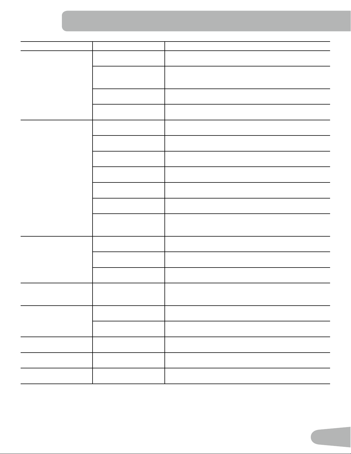
Maintenance Parts
A
EE
BB
AA
B
D
C
E
F
H
I
J
K
M
G
Y
X
P
Q
T
V
U
W
N
R
S
CC
DD
L
O
Z
A Console L Transport Wheel W Console Cable, Lower
B Seat Back M Stabilizer, Front X Shroud, Right
C Seat Cover N Heart Rate Cable, Lower Y Pedal, Right
D Water Bottle Holder O Drive Pulley Z Power Connector
E Handlebar, Side P Speed Sensor Magnet AA Shroud, Upper
F Seat Bottom Q Speed Sensor BB Shroud Cap
G Seat Adjustment Handle R Crank Arm CC Console Cable, Upper
H Rear Stabilizer S Servo Motor DD Heart Rate Cable, Upper
I Shroud, Left T Brake Assembly EE Console Mast
J Pedal, Left U Drive Belt
K Frame Assembly V Flywheel

38
TROUBLESHOOTING
Condition/Problem Things to Check Solution
No display/partial display/
unit will not turn on
Check electrical (wall)
outlet
Make sure unit is plugged into a functioning wall outlet.
Check connection at front
of unit
Connection should be secure and undamaged. Replace
adapter or connection at unit if either are damaged.
Check data cable integrity All wires in cable should be intact. If any are visibly crimped or
cut, replace cable.
Check data cable
connections/orientation
Be sure cable is connected securely and oriented properly.
Small latch on connector should line up and snap into place.
Check console display for
damage
Check for visual sign that console display is cracked or other-
wise damaged. Replace Console if damaged.
Console Display If Console only has partial display and all connections are ne,
replace the Console.
If the above steps do not resolve the problem, contact your lo-
cal distributor for further assistance.
Unit operates but Contact
HR not displayed
HR cable connection at
Console
Be sure cable is connected securely to Console.
HR cable box connection Be sure cables from handlebars and cable to Console are
secure and undamaged.
Sensor grip Be sure hands are centered on HR sensors. Hands must be
kept still with relatively equal pressure applied to each side.
Dry or calloused hands Sensors may have difculty with dried out or calloused hands.
A conductive electrode cream (heart rate cream) can help
make better conduct. These are available on the web or at
medical or some larger tness stores.
Static Handlebar If tests reveal no other issues, Static Handlebar should be
replaced.
Console displays “E2” er-
ror code
Check data cable integrity All wires in cable should be intact. If any are cut or crimped,
replace cable.
Check data cable
connections/orientation
Be sure cable is connected securely and oriented properly.
Small latch on connector should line up and snap into place.
Console Electronics If tests reveal no other issues, contact your local distributor for
further assistance.
No speed/RPM reading,
Console displays “Please
Pedal” error code
Check data cable integrity All wires in cable should be intact. If any are cut or crimped,
replace cable.
Check data cable
connections/orientation
Be sure cable is connected securely and oriented properly.
Small latch on connector should line up and snap into place.
Check magnet position
(requires shroud removal)
Magnet should be in place on pulley.
Check Speed Sensor
(requires shroud removal)
Speed sensor should be aligned with magnet and connected to
data cable. Realign sensor if necessary. Replace if there is any
damage to the sensor or the connecting wire.
Resistance does not
change (machine turns on
and operates)
Batteries (if equipped) Replace batteries and check for proper operation.
Check Console Check for visual sign that Console is damaged. Replace Con-
sole if damaged.
39
Condition/Problem Things to Check Solution
Check data cable integrity All wires in cable should be intact. If any are visibly crimped or
cut, replace cable.
Check data cable
connections/orientation
Be sure cable is connected securely and oriented properly.
Reseat all connections. Small latch on connector should line up
and snap into place.
Check Servo Motor
(requires shroud removal)
If magnets move, adjust until they are within the proper range.
Replace Servo Motor if not functioning properly.
If the above steps do not resolve the problem, contact your lo-
cal distributor for further assistance.
Console shuts off (enters
sleep mode) while in use
Check electrical (wall)
outlet
Make sure unit is plugged into a functioning wall outlet.
Check connection at front
of unit
Connection should be secure and undamaged. Replace
adapter or connection at unit if either are damaged.
Check data cable integrity All wires in the cable should be intact. If any are cut or crimped,
replace cable.
Check data cable
connections/orientation
Be sure cable is connected securely and oriented properly.
Small latch on connector should line up and snap into place.
Reset machine Unplug unit from electrical outlet for 3 minutes. Reconnect to
outlet.
Check magnet position
(requires shroud removal)
Magnet should be in place on pulley.
Check Speed Sensor
(requires shroud removal)
Speed sensor should be aligned with magnet and connected to
data cable. Realign sensor if necessary. Replace if there is any
damage to the sensor or the connecting wire.
Fan will not turn on or will
not turn off
Check data cable integrity All wires in cable should be intact. If any are cut or crimped,
replace cable.
Check data cable
connections/orientation
Be sure cable is connected securely and oriented properly.
Small latch on connector should line up and snap into place.
Reset machine Unplug unit from electrical outlet for 3 minutes. Reconnect to
outlet.
Fan will not turn on, but
Console operates
Check for blockage of fan Unplug unit from electrical outlet for 5 minutes. Remove mate-
rial from fan. If necessary, detach the Console to help with
removal. Replace the Console if unable to remove blockage.
Unit rocks/does not sit
level
Check leveler adjustment Adjust levelers until machine is level.
Check surface under unit Adjustment may not be able to compensate for extremely un-
even surfaces. Move machine to level area.
Pedals loose/unit difcult
to pedal
Check pedal to crank
connection
Pedal should be tightened securely to crank. Be sure connec-
tion is not cross threaded.
Clicking sound when
pedaling
Check pedal to crank arm
connection
Remove pedals. Make sure there is no debris on threads, and
reinstall the pedals.
Seat Assembly shifts /
squeaks when in use
Hardware Check hardware that attaches Seat assembly, and fully tighten
hardware.

Nautilus® Bowex® Schwinn® Universal®
8011245.060116.A
EN