
1
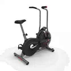
Schwinn® AD7 AirDyne® Bike Service Manual
8014178.021522.C
Service Manual
Nautilus, Inc., www.NautilusInc.com, 5415 Centerpoint Parkway, Groveport, OH 43125 U.S.A. - Customer Service: North America (800) 605-3369,
[email protected] | outside U.S. www.nautilusinternational.com | © 2016 Nautilus, Inc. | Schwinn, the Schwinn Quality logo, and AirDyne are
trademarks owned by or licensed to Nautilus, Inc., which are registered or otherwise protected by common law in the United States and other countries.
Polar® is a registered trademarks of its owner.
ORIGINAL DOCUMENT - ENGLISH VERSION ONLY
Table of Contents
Section Code Section Page Number
1 Important Safety Instructions 2
1 Safety Warning Labels and Serial Number 3
1 ReadingtheProductSpecicationLabel 3
1 Specications 3
1 Maintenance 4
1 Locking the Fan Assembly / Storage 5
1 Moving the Machine 5
1 Leveling the Machine 6
1 Replacing the Console Batteries 6
1 Troubleshooting 7
1 Console Service Mode 9
1 Console Error Codes 9
1 Maintenance Parts Exploded View 10
1 TorqueSpecications 11
1 Replacement Procedure Skill Level 11
Mechanical Procedures
2 Belt Tension Adjustment 12
Part Replacement
3 Pedals 16
4 Water Bottle Holder 18
5 Console 20
6 Console Mast 23
7 Transport Wheels 26
8 Levelers 28
9 Seat Post 30
10 Handlebar Arms and Foot Pegs 32
11 Crank Arm Assembly 35
12 Shrouds and Footpad 37
13 Fan Cage 39
14 Linkage Arms 41
15 RPM Sensor (Speed Sensor) 44
16 Drive Belt and Fan Assembly 47
17 Rear Idler Pulley 55
18 Crank Link Assembly 58
19 Power Inlet 61
8014236.021522.C

2
Important Safety Instructions and General Troubleshooting
Information for the Schwinn® AD7 AirDyne® Bike 8014188.021522.C
Service Procedures
Important Safety Instructions
This icon means a potentially hazardous situation which, if not avoided, could result in death or serious injury. Read and
understand all Warnings on this machine.
Before servicing or using this equipment, obey the following warnings:
Read and understand the Service Manual before working on the machine. Failure to obey the instructions and safety warnings
could cause injury to the service technician or bystanders.
• Keep bystanders and children away from the product being serviced at all times.
• Makesurethattherepairisdoneinanappropriateworkspaceawayfromfoottrafcandexposuretobystanders.
• Disconnect all power to the machine before you service it.
• Some components of the equipment can be heavy or awkward. Enlist the service of a second person when you do maintenance steps involving
these components. Do not try to do heavy or awkward steps on your own.
• If replacement parts are necessary, use only genuine replacement parts and hardware supplied by Nautilus. Failure to use genuine replacement
parts can cause a risk to users, keep the machine from operating correctly and void the warranty.
• Be sure that all warning stickers and instructional placards applied to the product stay present and in good condition when doing maintenance or
replacing components. If at any time the Warning labels become loose, unreadable or dislodged, replace the labels. If purchased in US/Canada,
contact Customer Service for replacement labels. If purchased outside US/Canada, contact your local distributor for them..
• Do not try to change the design or functionality of the machine being serviced as this can adversely affect user safety.
• Donotputthemachinebackinserviceuntilallshrouds,instructions,warninglabelsandcorrectfunctionalityhavebeenveriedandtestedfor
correct performance.
• SAVE THESE INSTRUCTIONS.
Nautilus, Inc., www.NautilusInc.com, 5415 Centerpoint Parkway, Groveport, OH 43125 U.S.A. - Customer Service: North America (800) 605-3369, [email protected] | outside U.S. www.nautilusinternational.com | © 2016
Nautilus, Inc. | Schwinn, the Schwinn Quality logo, and AirDyne are trademarks owned by or licensed to Nautilus, Inc., which are registered or otherwise protected by common law in the United States and other countries.
Polar® is a registered trademarks of its owner. | ORIGINAL DOCUMENT - ENGLISH VERSION ONLY
NOTICE: This document provides important safety instructions, adjustments, and general troubleshooting information for the maintenance of the Schwinn® AD7 AirDyne®
Bike.
If you need assistance, please call Schwinn Customer Service (if purchased in US/Canada) or your local distributor (if purchased
outside US/Canada). To nd your local distributor, go to: www.nautilusinternational.com
This icon means a potentially hazardous situation which, if not avoided, could result in death or serious injury. Read and understand
all Warnings on this machine.
3
Safety Warning Labels and Serial Numbers
Specications
Reading the Product Specication Decal
TheManufactureDateontheProductSpecicationDecal
is a date code: YY/WW (year/week).
Manufacture Date Code: YYWW
Maximum User Weight: 350 lbs. (159 kg)
Machine Weight: 113 lbs. (51.3 kg)
Power Requirements: 2 D Batteries (LR20)
Operating Voltage: 3VDC
Regulatory Approvals:
Optional AC Power Adapter: UL listed, Rated 120V 60Hz Input,
9VDC, 1500mA Output. Class 2.
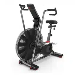
53”
134.6 cm
53”
134.6 cm
26.5”
67.3 cm
Product specification
Serial number
WARNING!
• Keep children away.
• Not intended for use by anyone under 14 years of age.
• Prior to use, read and understand the Owner’s Manual.
• Injury or death is possible if Caution is not used while using
this machine.
• Cease exercise if you feel faint or dizzy.
• The maximum user weight for this machine is158kg (350lb).
•Keepbody,clothingandtnessaccessoriesclearofall
moving parts.
• Inspect the equipment before use and do not use if the
machine appears damaged or inoperable.
• Replace any “Caution”, “Warning” or “Danger” label that is
illegible, damaged, or removed.
• This machine is for home use only.
• When put in a home, lock the machine when not in
operation.
• The heart rate displayed is an approximation and should be
used for reference only.
• Consult a physician prior to using any exercise equipment.

4
Read all maintenance instructions fully before you start any repair work. In some conditions, an assistant is required to do
the necessary tasks.
!Equipment must be regularly examined for damage and repairs. The owner is responsible to make sure that
regular maintenance is done. Worn, damaged or loose components must be repaired or replaced
immediately. Only manufacturer supplied components can be used to maintain and repair the equipment.
If at any time the Warning labels become loose, unreadable or dislodged, replace the labels. If purchased
in US/Canada, contact Customer Service for replacement labels. If purchased outside US/Canada, contact
your local distributor for them.
Disconnect all power to the machine before you service it.
Daily: Before each use, examine the exercise machine for loose, broken, damaged, or
worn parts. Do not use if found in this condition. Repair or replace all parts at the
rst sign of wear or damage. After each workout, use a damp cloth to wipe your
machine and Console free of moisture.
Note: Avoid excessive moisture on the Console.
NOTICE: If necessary, only use a mild dish soap with a soft cloth to clean the
Console. Do not clean with a petroleum based solvent, automotive
cleaner, or any product that contains ammonia. Do not clean the
Console in direct sunlight or at high temperatures. Be sure to keep the
Console free of moisture.
Weekly: Check pedals, crank arms and handlebars and tighten as necessary.
Since this machine operates with a xed gear, do not back, or
reverse, pedal. Doing so may loosen the Pedals, which could result in
damage to the machine and/or injury to the user. Never operate this
machine with loose Pedals.
Clean the machine to remove any dust, dirt, or grime from the surfaces.
Check for smooth seat operation. If needed, sparingly apply a thin coating of
silicone lube to ease operation.
Silicone lubricant is not intended for human consumption. Keep out
of reach of children. Store in a safe place.
Note: Do not use petroleum based products.
Monthly
or after 20
hours:
Make sure all bolts and screws are tight. Tighten as necessary.
Check drive belt for signs of wear. Rotate crank arms by hand and observe the
belt through the fan cage.
Be aware that the Crank Arms, Handlebars and Resistance Fan are
connected and when any of these parts move, the others do as well.
Only use replacement Pedals available from Nautilus. Other brands of Pedals may not be designed
for Indoor Cycling or this product, and can cause danger to users and bystanders , and will void the
warranty.
5
Locking the Fan Assembly / Storage
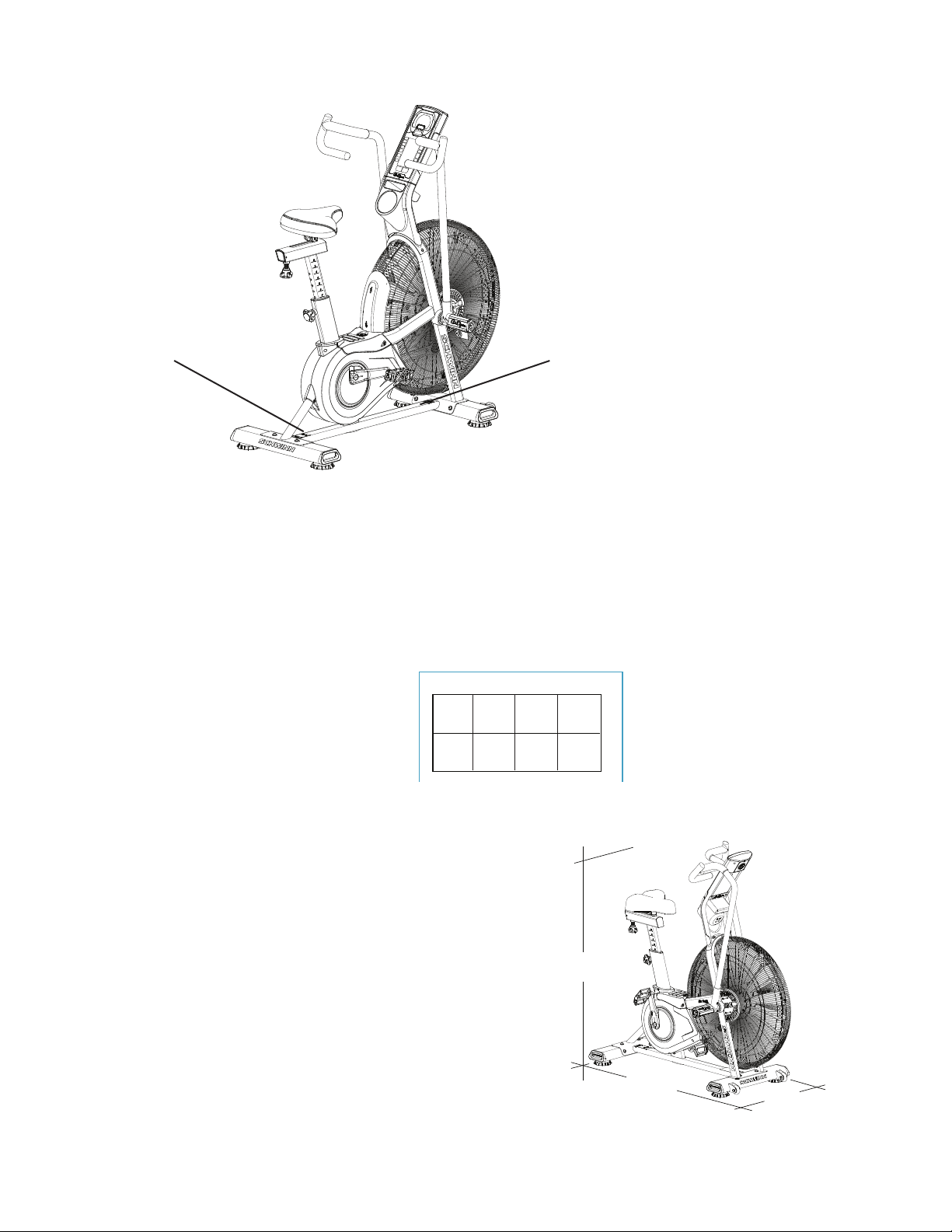
When the machine is not in use, be sure to lock the Fan
Assembly with the Transport and Immobilization Strap. The
fan assembly should be locked for storage of the machine.
For safe storage of the machine, remove the
batteries and install the Transport and
Immobilization Strap to secure the Resistance Fan.
Place the machine in a secure location away from
children and pets. Be aware that the Pedals,
Handlebars and Resistance Fan are connected and
when any of these parts move, the others do as well.
To lock the Fan Assembly:
1. Move the Pedals so that one Crank Arm is as close as
possible to the Seat Post.
2. Wrap the Transport and Immobilization Strap (T) around
the Crank Arm and the Seat Post and put the end of the
strap through the metal ring. Tighten the strap to prevent
movement of the Pedals and secure the strap.
Moving the Machine
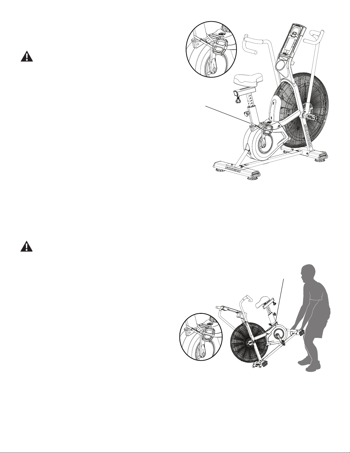
The machine may be moved by one or more persons depending on their physical abilities and capacities.
Make sure that you and others are all physically t and able to move the machine safely. Use proper safety
precautions and lifting techniques.
1. Secure the Crank Arm to the Seat Post with the Transport
and Immobilization Strap (T).
2. Use the Rear Stabilizer to carefully lift the machine onto
the transport rollers.
Note: Be sure to keep the fan assembly clear of the oor.
3. Push the machine into position.
4. Carefully lower the machine into position.
NOTICE: Be careful when you move the machine. Abrupt
motions can aect the computer operation.
T
T
6
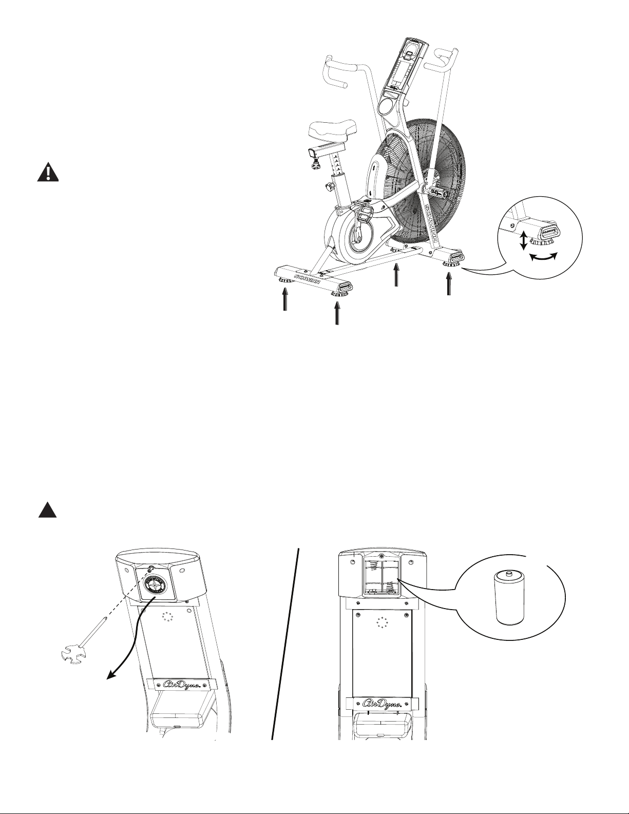
Leveling the Machine
The machine needs to be leveled if your workout
area is uneven. Levelers are on each side of the
Stabilizers. To adjust:
1. Place the machine in your workout area.
2. Turn the stabilizer feet to adjust until they are
evenly balanced and in contact with the oor.
Do not adjust the levelers to such a height
that they detach or unscrew from the
machine. Injury to you or damage to the
machine can occur.
Make sure the machine is level and stable before
you exercise.
Replacing the Console Batteries
The Console will display the Battery Indicator icon when the batteries are around 25% of their rated power during power
up. If you use rechargeable batteries, the optional power adapter will not recharge the batteries.
To open the battery bay, loosen the preinstalled screw in the cover. When replacing the batteries, make sure the batteries
point in the +/- direction shown in the battery bay.
Note: The console uses D size batteries (LR20)
!Do not mix old and new batteries.
Do not mix alkaline, standard (carbon-zinc), or rechargeable (Ni-Cd, Ni-MH, etc) batteries.
X2
+
–

7
Troubleshooting
Condition/Problem Things to Check Solution
Console will not power up/
turn on/start
If bike has AC adapter,
check electrical (wall)
outlet
Make sure unit is plugged into a functioning wall outlet.
If bike has AC adapter,
check connection at unit
Connection should be secure and undamaged. Replace
adapter or connection at unit if either are damaged.
If bike has batteries,
check Battery Indicator
on console or check
batteries.
Make sure batteries are installed correctly. If batteries are
correctly installed, replace with a set of new batteries.
Check data cable integrity All wires in cable should be intact. If any are visibly crimped or
cut, replace cable.
Check data cable
connections/orientation
Make sure cable is connected securely and oriented properly.
Small latch on connector should line up and snap into place.
Check console display for
damage
Check for visual sign that console display is cracked or
otherwise damaged. Replace Console if damaged.
If the above steps do not resolve the problem, contact
Customer Care for further assistance.
Speed displayed is not
accurate
Check Speed Sensor
Magnet position (requires
fan cover removal)
Speed Sensor Magnets should be in place on Fan assembly.
Speed displayed is always
“0”/stuck in Pause mode
Data cable Make sure the data cable is connected to the back of the
Console and the main frame assembly.
Speed Sensor (requires
fan cover removal)
Make sure the Speed Sensor Magnets and the Speed Sensor
are in place.
No speed/RPM reading Check data cable integrity All wires in cable should be intact. If any are cut or crimped,
replace cable.
Check data cable
connections/orientation
Be sure cable is connected securely and oriented properly.
Small latch on connector should line up and snap into place.
Check Speed Sensor
Magnet position (requires
fan cover removal)
Magnets should be in place on Fan assembly.
Check Speed Sensor
Assembly (requires fan
cover removal)
Speed Sensor Assembly should be aligned with magnets and
connected to data cable. Realign sensor if necessary. Replace
if there is any damage to the sensor or the connecting wire.
Console displays battery
icon
Batteries Replace batteries
Unit operates but
Telemetric Heart Rate not
displayed
Chest Strap (optional) Strap should be “POLAR®” compatible and uncoded. Make
sure strap is directly against skin and contact area is wet.
Chest Strap Batteries If strap has replaceable batteries, install new batteries.
Interference Try moving unit away from sources of interference (TV, Micro-
wave, etc).
Replace Chest Strap If interference is eliminated and HR does not function, replace
strap.
Replace Console If HR still does not function, replace Console.
Console shuts o (enters
sleep mode) while in use
Check data cable integrity All wires in the cable should be intact. If any are cut or crimped,
replace cable.
Check data cable
connections/orientation
Be sure cable is connected securely and oriented properly.
Small latch on connector should line up and snap into place.

8
Condition/Problem Things to Check Solution
If bike has batteries,
check Battery Indicator
on console or check
batteries.
Make sure batteries are installed correctly. If batteries are
correctly installed, replace with a set of new batteries.
Check Speed Sensor
Magnet position (requires
fan cover removal)
Speed Sensor Magnets should be in place on Fan assembly.
Check Speed Sensor
Assembly
Contact Customer Care for further assistance.
Console displays “err 1”
message
Check Console keypad for
stuck key
Contact Customer Care for further assistance.
Unit rocks/does not sit
level
Check leveler adjustment Leveling feet may be turned in or out to level bike.
Check surface under unit Adjustment may not be able to compensate for extremely un-
even surfaces. Move bike to level area.
Pedals loose/unit dicult
to pedal
Check pedal to crank
connection
Pedal should be tightened securely to crank arm. Be sure con-
nection is not cross-threaded.
Check crank arm to axle
connection
Crank arm should be tightened securely to axle. (Screw torque
= 60 N.m.)
Crank link to pulley
connection
If the left crank arm still feels loose with correct torque applied
and the crank link shaft is moving with the crank arm, replace
the crank link assembly.
Clicking sound when
pedaling
Check pedal to crank
connection
Remove pedals. Make sure there is no debris on threads, and
reinstall the pedals.
Check fan alignment
(requires fan cover
removal)
Refer to the “Adjust the Belt Tension” procedure in the Service
Manual.
Seat post movement Check locking pin Be sure adjustment pin is locked into one of the seat post
adjustment holes.
Check locking knob Be sure knob is securely tightened.
Handlebar arms click/tick
during movement
Check hardware Screws at the base of handlebar arms should be tightened
securely. (Screw torque = 40 N.m.)
9
Console Service Mode
The Console Service Mode lets you see the total time and distance the machine has been used, or nd out which version
of Firmware is installed.
1. Hold down the STOP/RESET button and Decrease () button together for 3 seconds while in the Idle Mode to go into
the Console Service Mode.
2. The Console display shows the machine statistics:
• Total Machine Time—number of hours (in Time/Interval eld). Maximum display is 9999.
• Total Machine Distance—number of miles (in cumulative metrics eld).
Push the Decrease button to go to the metric display option:
• Total Machine Time—number of hours (in Time/Interval eld). Maximum display is 9999.
• Total Machine Distance—number of kilometers in 10-kilometer increments (in cumulative metrics eld).
3. Push STOP/RESET to exit Console Service Mode. Push the Decrease button to go to the next option.
4. The Console display shows the Firmware Version.
5. Push STOP/RESET to exit Console Service Mode.
In Service Mode if the Console does not receive any input in approximately 5 minutes, it goes into Sleep Mode.
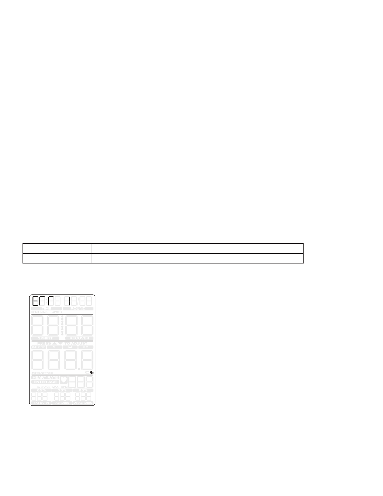
Console Error Codes
Console display error Condition
Err 1 Stuck button - any button is depressed longer than 90 seconds.
Console error display format
Stuck button
10
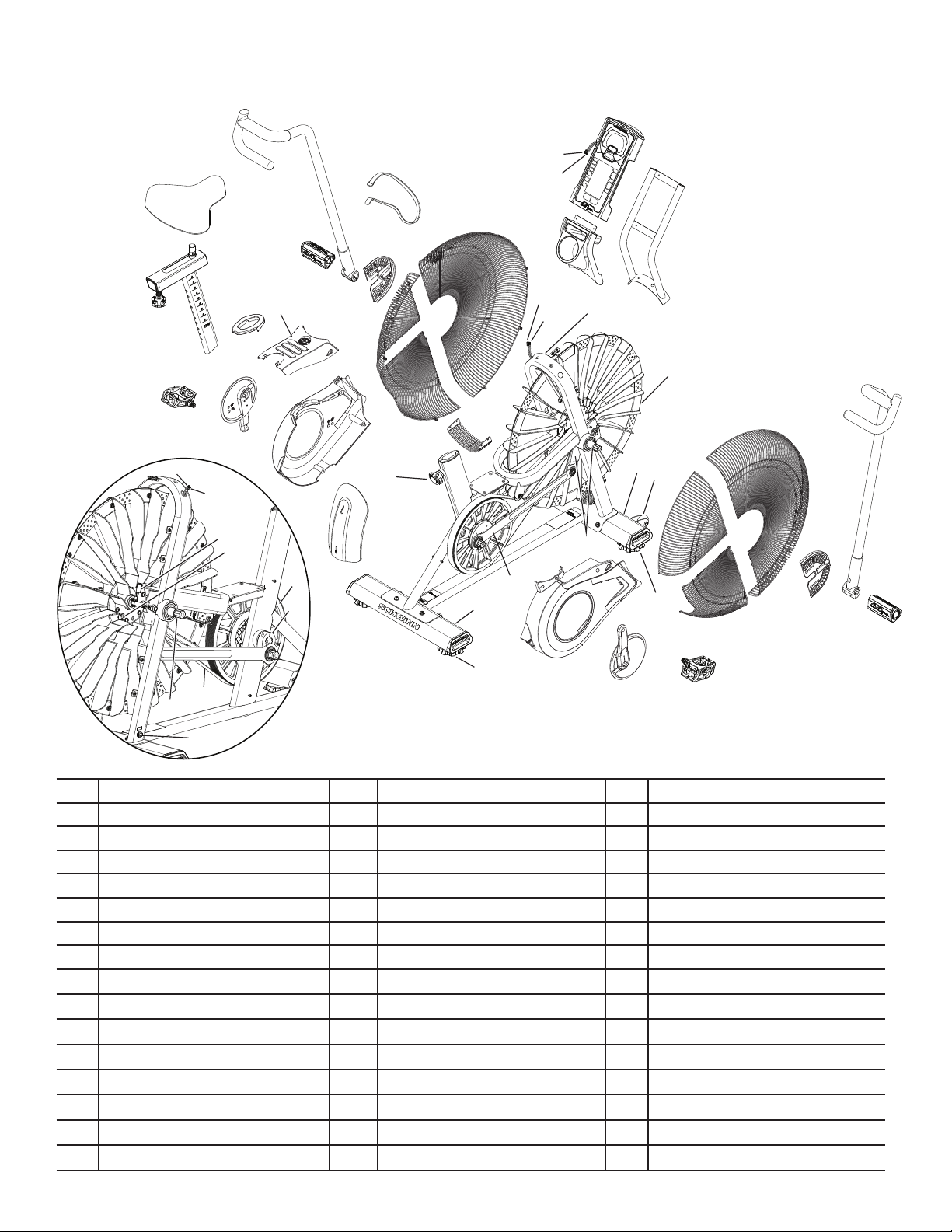
Maintenance Parts
Your machine may dier. Use only as a guide.
A Console Q Leveler GG Power Inlet Assembly
B Console Mast R Seat Adjustment Knob HH Fan Cage, Upper Left
C Water Bottle Holder S Shroud, Left II Fan Cage, Lower Left
D Frame T Crank Arm, Left JJ Fan Cage, Lower Filler
E Stabilizer, Front U Pedal, Left KK Linkage Arm
F Transport Wheel V Shroud, Top LL Arm Pivot, Right
G Fan Cage, Upper Right W Foot Step Pad MM Arm Pivot, Left
H Fan Cage, Front X Grommet NN Resistance Fan Assembly
I Fan Cage Side Cover Y Seat Post OO RPM (Speed) Sensor Assembly
J Fan Cage, Lower Right Z Seat PP Speed Sensor Magnets
K Handlebar, Right AA Handlebar, Left QQ Drive Pulley
L Foot Peg, Right BB Foot Peg, Left RR Drive Belt
M Pedal, Right CC Strap, Transport/Immobilization SS Crank Link Assembly
N Crank Arm, Right DD Data Cable, Upper TT AirDyne® Air Diverter
O Shroud, Right EE Power Wire, Upper
P Stabilizer, Rear FF Data Cable, Lower
B
A
C
D
EFG
H
H
I
I
J
K
L
M
N
O
P
Q
Q
R
S
T
U
V
X
Y
Z
AA
BB
CC DD
EE
FF
GG
HH
II JJ
KK
LL
W
FF
GG
NN
OO
PP
(X3)
QQ
RR
MM
SS
GG
NN
TT

11
REPLACEMENT PROCEDURE SKILL LEVEL
Level I : Low - very little mechanical knowledge or exposure.
Level II : Intermediate - some experience with mechanical procedures
Level III : Advanced - knowledgeable about mechanical procedures
!Disconnect all power to the machine before you service it.
When disposing of old parts, obey the applicable local and provincial requirements.
For instructions to replace the following parts, please refer to the Assembly Manual for your bike:
• AC Adapter
• Seat
• Front Stabilizer
• Rear Stabilizer
Torque Specications
60 N.m
40 N.m
40 N.m
60 N.m
≤ 19 N.m
(X2)
≤ 19 N.m
(X2)
≤ 19 N.m
10 N.m
12
Adjust the Belt Tension on the Schwinn® AD7 AirDyne® Bike
Skill Level: II
8014189.021522.C
Replacement Procedure
NOTICE: This document provides instructions for the adjustment of the Drive Belt tension on the Schwinn® AD7 AirDyne® Bike.
If you need assistance, please call Schwinn Customer Service (if purchased in US/Canada) or your local distributor (if purchased out-
side US/Canada). To nd your local distributor, go to: www.nautilusinternational.com
This icon means a potentially hazardous situation which, if not avoided, could result in death or serious injury. Read and understand
all Warnings on this machine.
Tools Required (not included)
19mm or 3/4” open end wrench
10mm open end wrench
#2 Phillips screwdriver
28mm spacer (or extra drive belt)
Important Safety Instructions
This icon means a potentially hazardous situation which, if not avoided, could result in death or serious injury. Read and
understand all Warnings on this machine.
Before servicing or using this equipment, obey the following warnings:
Read and understand the Service Manual before working on the machine. Failure to obey the instructions and safety warnings
could cause injury to the service technician or bystanders.
• Keep bystanders and children away from the product being serviced at all times.
• Makesurethattherepairisdoneinanappropriateworkspaceawayfromfoottrafcandexposuretobystanders.
• Disconnect all power to the machine before you service it.
• Some components of the equipment can be heavy or awkward. Enlist the service of a second person when you do maintenance steps involving
these components. Do not try to do heavy or awkward steps on your own.
• If replacement parts are necessary, use only genuine replacement parts and hardware supplied by Nautilus. Failure to use genuine replacement
parts can cause a risk to users, keep the machine from operating correctly and void the warranty.
• Be sure that all warning stickers and instructional placards applied to the product stay present and in good condition when doing maintenance or
replacing components. If at any time the Warning labels become loose, unreadable or dislodged, replace the labels. If purchased in US/Canada,
contact Customer Service for replacement labels. If purchased outside US/Canada, contact your local distributor for them..
• Do not try to change the design or functionality of the machine being serviced as this can adversely affect user safety.
• Donotputthemachinebackinserviceuntilallshrouds,instructions,warninglabelsandcorrectfunctionalityhavebeenveriedandtestedfor
correct performance.
• SAVE THESE INSTRUCTIONS.
Nautilus, Inc., www.NautilusInc.com, 5415 Centerpoint Parkway, Groveport, OH 43125 U.S.A. - Customer Service: North America (800) 605-3369, [email protected] | outside U.S. www.nautilusinternational.com | © 2016
Nautilus, Inc. | Schwinn, the Schwinn Quality logo, and AirDyne are trademarks owned by or licensed to Nautilus, Inc., which are registered or otherwise protected by common law in the United States and other countries.
Polar® is a registered trademarks of its owner. | ORIGINAL DOCUMENT - ENGLISH VERSION ONLY
13
Note: Your machine may not match the image. For reference only.
1. To test the Drive Belt tension, sit on the bike and use the pedals and
handlebar arms at approximately 20 RPM. Then accelerate quickly (speed
burst) to your maximum ability and feel whether the Drive Belt slips. If
the pedals and arms move normally with no skipping (slip), the tension is
correct.
If the tension is correct—go to Step 19.
If the tension is too loose or too tight—continue to Step 2.
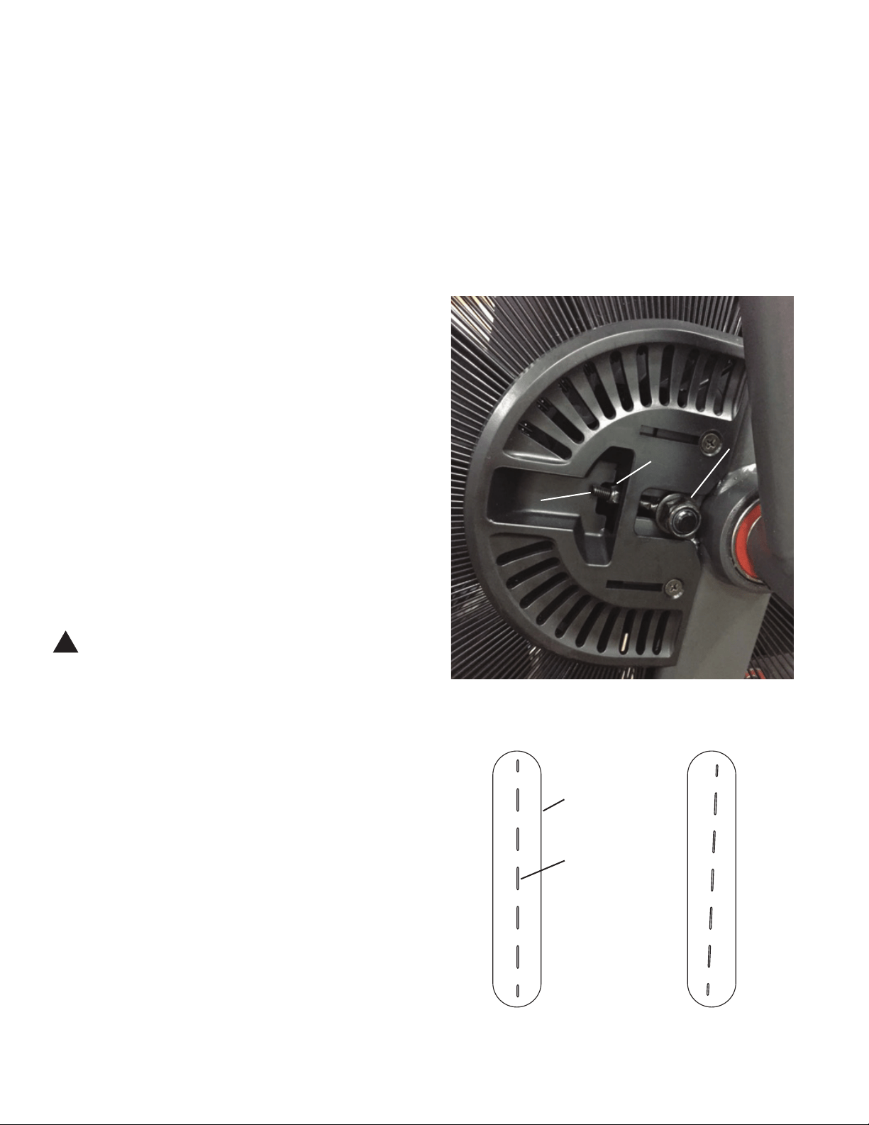
2. Using a 19mm open end wrench, loosen the Fan spindle lock nuts
(A) on both sides of the machine.
3. Using a 10mm open end wrench, adjust the Tension Adjustment
Nuts (B) on the Threaded Tensioner (C) on both sides of the machine.
Gradually turn the Adjustment Nut a 1/4 turn on each side. Tighten
(clockwise) the Adjustment Nuts to increase the belt tension, loosen
(counter-clockwise) to decrease.
NOTICE: Make sure to adjust the tension evenly on both sides of the
machine.
4. Make sure the Fan’s center plane is aligned with the center of the
bike. (See Figures 1 and 2.) If the Fan is not aligned, adjust the Tension
Adjustment Nuts (B). Carefully turn the Crank Arms and check the
movement of the Drive Belt. The Crank Arms and Fan Assembly should
move as one.
!Be sure to keep ngers clear of all pinch hazards when you
turn the Crank Arms.
Repeat Step 1. Adjust the belt tension again if necessary.
5. Retighten the 19mm Fan spindle lock nuts (A). Make sure not to
rotate the shaft as this could damage the RPM Sensor.
6. Test ride the machine to as high a speed as possible, and listen for
unusual noises.
If the machine operates with no popping noises—go to Step 19.
If the Drive Belt or Fan makes noises—continue to Step 7.
NOTICE: It may be necessary to remove the Shrouds for this procedure. Refer to the “Replace the Shrouds” procedure
Figure 1 (top view) – Correct Figure 2 – Incorrect
B
C
A
Fan
center
plane
Fan
cage
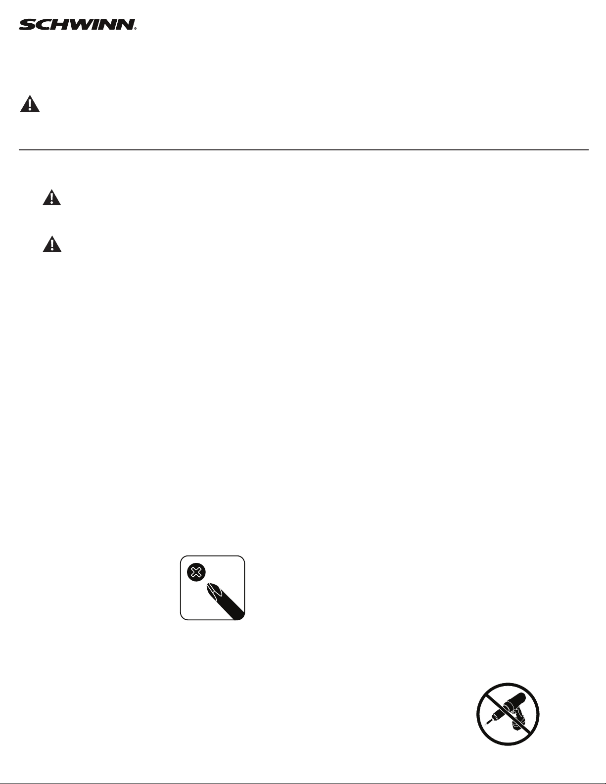
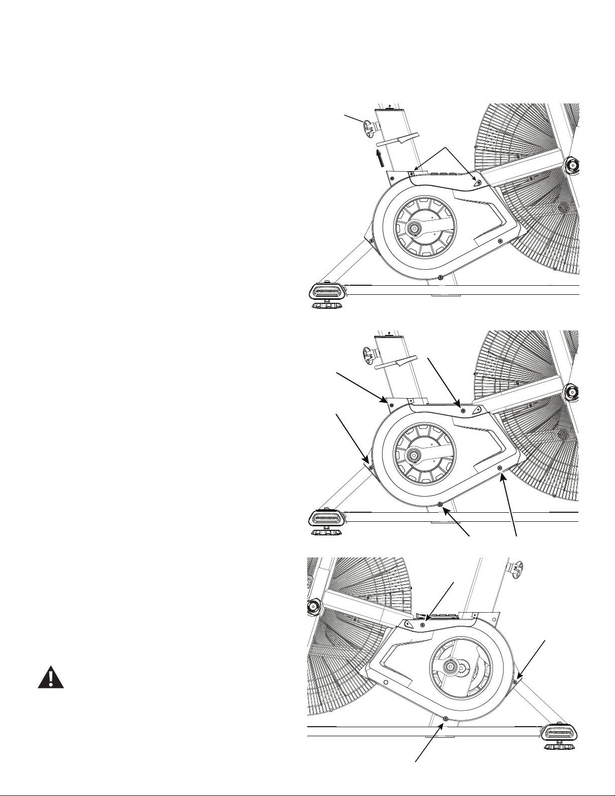
14
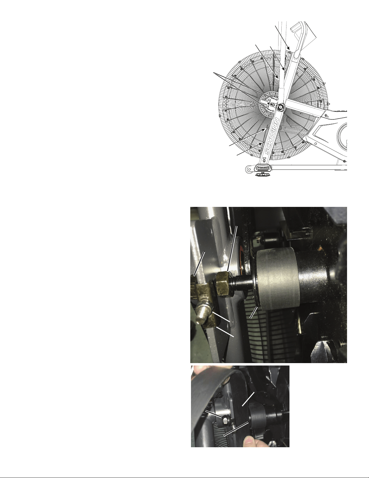
7. Loosen and remove the indicated screws that attach the Fan
Adjustment Plate Covers (*) and Front Fan Cage to the frame. Carefully
remove the front Fan Cage sections and Fan Adjustment Plate Covers.
Set them safely aside for reassembly.
NOTICE: Hold each section of the Fan Cage as you loosen the
screws so that it does not fall. If necessary, loosen and
remove the screws that attach the sections of the Fan
Cage to each other.
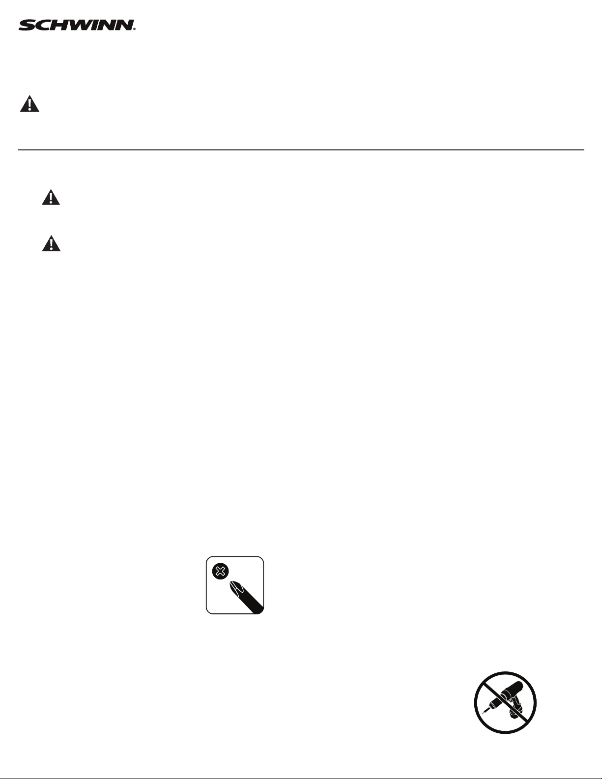
8. Make sure the Drive Belt is centered on the Fan hub (E) and the
Drive Pulley. The Fan hub should have at least 1 groove visible to the left
of the belt, and not extend over the right side of the hub.
9. Check the side-to-side position of the Fan. The outer face of the Fan
hub (E) should be 28mm from the frame bracket. (28mm = width of Drive
Belt.)
Hand tighten the Fan spindle jam nuts (D) to secure the side-to-side
position of the Fan hub and lock nuts (A) as necessary to align the Fan
Pulley.
10. Loosen the Tension Adjustment Nuts (B) on each side of the Fan
shaft until the Spindle Clips (G) are loose.
11. Tighten the Tension Adjustment Nuts (B) until the Spindle Clips
(G) are not loose when moving them by hand. Tighten the right and left
Adjustment Nuts 2 full turns.
Right side – Fan hub alignment (front top view)
*
BB
DD
GG
EE
AA
28mm28mm
AA
EE
15
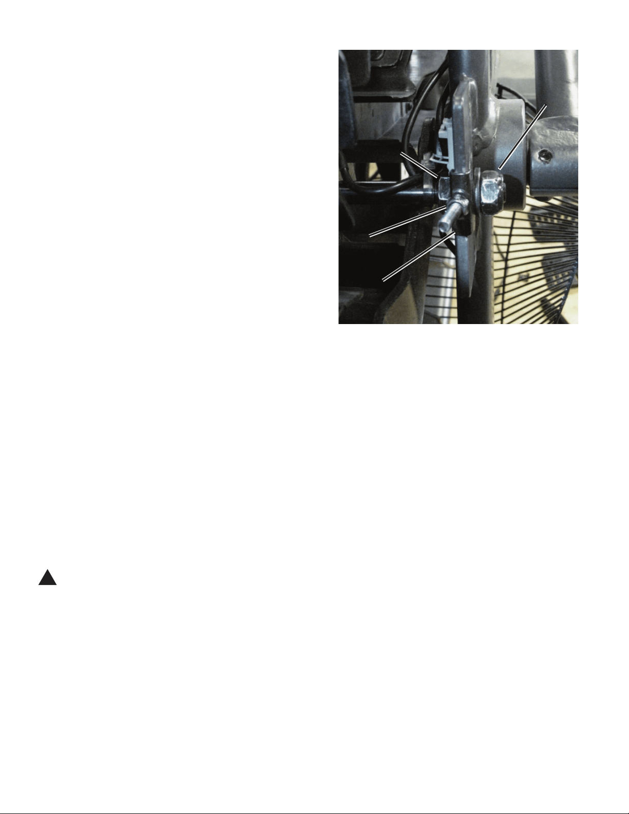
12. Tighten the left Tension Adjustment Nut (B, on the side of the Fan
without the belt) an additional 2 full turns.
13. Reinstall Fan Cage and test ride the machine to as high a speed as
possible.
If the machine operates with no popping noises—go to Step 17.
If the Drive Belt or Fan makes noises—continue to Step 14.
14. Tighten the left Tension Adjustment Nut (B, on the side of the Fan
without the belt) 1/2 turn at a time, and test for quiet operation. Repeat
until the noise is gone. If the nut is adjusted more than 2 1/2 turns, the
Fan Pulley (E) position may need adjustment. This is necessary if the Fan
starts to make additional noise.
If the machine operates with no popping noises—go to Step 17.
If the Drive Belt or Fan makes additional noises—continue to Step 15.
15. Remove the Front Fan Cage (see Step 7). Loosen the Tension
Adjustment Nuts (B) until the Spindle Clips (G) are loose. Loosen the right
Fan spindle jam nut (D). Tighten the left Fan spindle jam nut 1 full turn
(toward the Frame mount bracket). Retighten the right Fan spindle jam nut
to the mount bracket.
Repeat Steps 11-14.
16. Reinstall the Fan Cage.
17. Using the 19 mm open end wrench, tighten the Fan spindle lock nuts (A).
18. Reinstall the Fan Adjustment Plate Covers.
19. Final Inspection
Inspect your machine to ensure that all hardware is tight and components
are properly assembled.
!Do not use until the machine has been fully assembled and
inspected for correct performance in accordance with the
Owner’s Manual.
Left side – Fan tension adjustment (top front view)
AA
BB
GG
DD
16
Replace the Pedals on the Schwinn® AD7 AirDyne® Bike
Skill Level: I
8014190.021522.C
Replacement Procedure
NOTICE: This document provides instructions for the replacement of the Pedals on the Schwinn® AD7 AirDyne® Bike.
If you need assistance, please call Schwinn Customer Service (if purchased in US/Canada) or your local distributor (if purchased out-
side US/Canada). To nd your local distributor, go to: www.nautilusinternational.com
This icon means a potentially hazardous situation which, if not avoided, could result in death or serious injury. Read and understand
all Warnings on this machine.
Tools Required (not included)
Pedal wrench
or 15 mm open end wrench
Important Safety Instructions
This icon means a potentially hazardous situation which, if not avoided, could result in death or serious injury. Read and
understand all Warnings on this machine.
Before servicing or using this equipment, obey the following warnings:
Read and understand the Service Manual before working on the machine. Failure to obey the instructions and safety warnings
could cause injury to the service technician or bystanders.
• Keep bystanders and children away from the product being serviced at all times.
• Makesurethattherepairisdoneinanappropriateworkspaceawayfromfoottrafcandexposuretobystanders.
• Disconnect all power to the machine before you service it.
• Some components of the equipment can be heavy or awkward. Enlist the service of a second person when you do maintenance steps involving
these components. Do not try to do heavy or awkward steps on your own.
• If replacement parts are necessary, use only genuine replacement parts and hardware supplied by Nautilus. Failure to use genuine replacement
parts can cause a risk to users, keep the machine from operating correctly and void the warranty.
• Be sure that all warning stickers and instructional placards applied to the product stay present and in good condition when doing maintenance or
replacing components. If at any time the Warning labels become loose, unreadable or dislodged, replace the labels. If purchased in US/Canada,
contact Customer Service for replacement labels. If purchased outside US/Canada, contact your local distributor for them..
• Do not try to change the design or functionality of the machine being serviced as this can adversely affect user safety.
• Donotputthemachinebackinserviceuntilallshrouds,instructions,warninglabelsandcorrectfunctionalityhavebeenveriedandtestedfor
correct performance.
• SAVE THESE INSTRUCTIONS.
Nautilus, Inc., www.NautilusInc.com, 5415 Centerpoint Parkway, Groveport, OH 43125 U.S.A. - Customer Service: North America (800) 605-3369, [email protected] | outside U.S. www.nautilusinternational.com | © 2016
Nautilus, Inc. | Schwinn, the Schwinn Quality logo, and AirDyne are trademarks owned by or licensed to Nautilus, Inc., which are registered or otherwise protected by common law in the United States and other countries.
Polar® is a registered trademarks of its owner. | ORIGINAL DOCUMENT - ENGLISH VERSION ONLY
17
Note: Your machine may not match the image. For reference only.
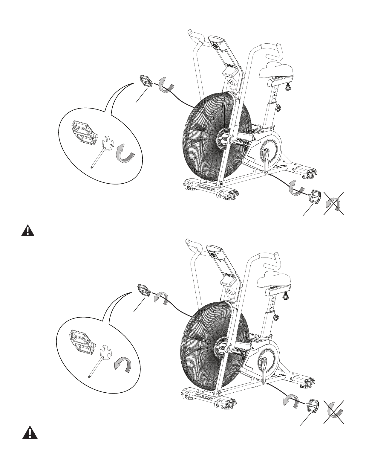
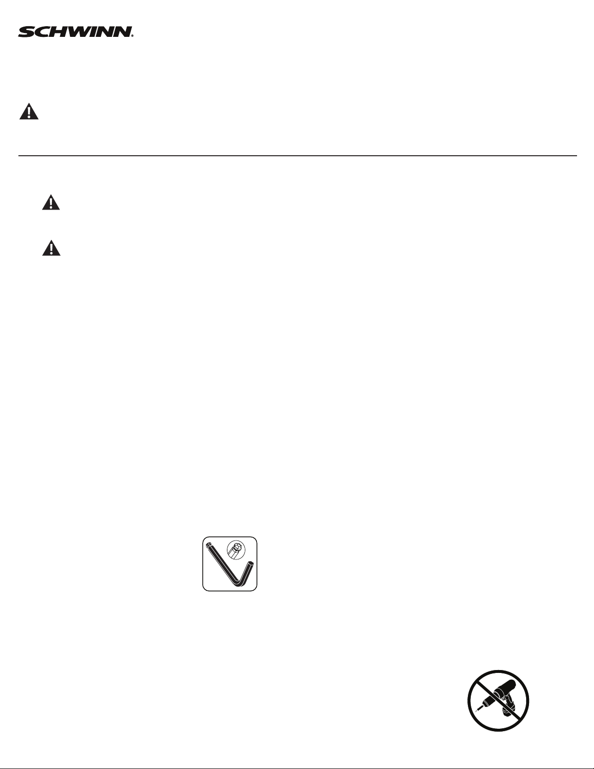
1. Loosen and remove the old Pedals. Discard the old Pedals.
Note: The Left Pedal is reverse-threaded. Orientation is based
from a seated position on the bike. The Left Pedal has an “L”,
the Right Pedal an “R”.
2. Install the new Pedals. Carefully align the threads and hand tighten
to prevent cross-threading. Then tighten fully with pedal wrench.
If the threads strip due to improper installation, then the Pedals
can disengage from the bike and/or break while under usage,
which can result in serious injury to the user.
Note: The Left Pedal is reverse-threaded. Be sure to attach
Pedals on the correct side of the Bike. Orientation is based
from a seated position on the bike. The Left Pedal has an “L”,
the Right Pedal an “R”.
3. Final Inspection
Inspect your machine to ensure that all hardware is tight and components
are properly assembled.
Do not use until the machine has been fully assembled and
inspected for correct performance in accordance with the
Owner’s Manual.
(L)
(R)
(L)
(R)
18
Replace the Water Bottle Holder
on the Schwinn® AD7 AirDyne® Bike Skill Level: I
8014191.021522.C
Replacement Procedure
NOTICE: This document provides instructions for the replacement of the Water Bottle Holder on the Schwinn® AirDyne® Pro Bikes.
If you need assistance, please call Schwinn Customer Service (if purchased in US/Canada) or your local distributor (if purchased out-
side US/Canada). To nd your local distributor, go to: www.nautilusinternational.com
This icon means a potentially hazardous situation which, if not avoided, could result in death or serious injury. Read and understand
all Warnings on this machine.
Tools Required (not included)
#2 Phillips screwdriver
Important Safety Instructions
This icon means a potentially hazardous situation which, if not avoided, could result in death or serious injury. Read and
understand all Warnings on this machine.
Before servicing or using this equipment, obey the following warnings:
Read and understand the Service Manual before working on the machine. Failure to obey the instructions and safety warnings
could cause injury to the service technician or bystanders.
• Keep bystanders and children away from the product being serviced at all times.
• Makesurethattherepairisdoneinanappropriateworkspaceawayfromfoottrafcandexposuretobystanders.
• Disconnect all power to the machine before you service it.
• Some components of the equipment can be heavy or awkward. Enlist the service of a second person when you do maintenance steps involving
these components. Do not try to do heavy or awkward steps on your own.
• If replacement parts are necessary, use only genuine replacement parts and hardware supplied by Nautilus. Failure to use genuine replacement
parts can cause a risk to users, keep the machine from operating correctly and void the warranty.
• Be sure that all warning stickers and instructional placards applied to the product stay present and in good condition when doing maintenance or
replacing components. If at any time the Warning labels become loose, unreadable or dislodged, replace the labels. If purchased in US/Canada,
contact Customer Service for replacement labels. If purchased outside US/Canada, contact your local distributor for them..
• Do not try to change the design or functionality of the machine being serviced as this can adversely affect user safety.
• Donotputthemachinebackinserviceuntilallshrouds,instructions,warninglabelsandcorrectfunctionalityhavebeenveriedandtestedfor
correct performance.
• SAVE THESE INSTRUCTIONS.
Nautilus, Inc., www.NautilusInc.com, 5415 Centerpoint Parkway, Groveport, OH 43125 U.S.A. - Customer Service: North America (800) 605-3369, [email protected] | outside U.S. www.nautilusinternational.com | © 2016
Nautilus, Inc. | Schwinn, the Schwinn Quality logo, and AirDyne are trademarks owned by or licensed to Nautilus, Inc., which are registered or otherwise protected by common law in the United States and other countries.
Polar® is a registered trademarks of its owner. | ORIGINAL DOCUMENT - ENGLISH VERSION ONLY
19
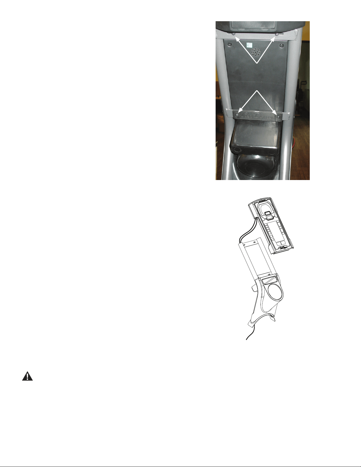
Note: Your machine may not match the image. For reference only.
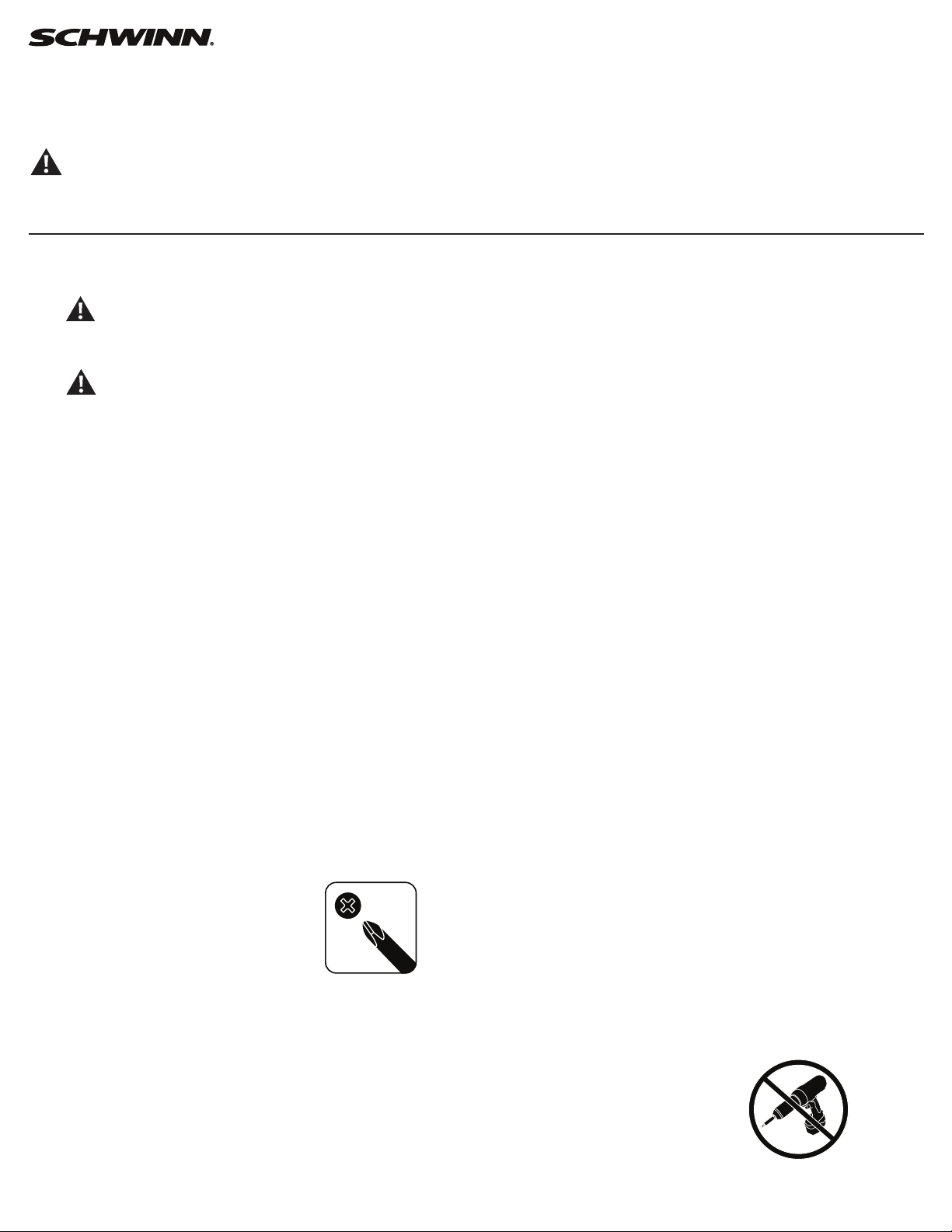
1. Loosen and remove the indicated screws that attach the Water Bottle
Holder to the Mast and Console. Set the screws safely aside.
2. Remove the Water Bottle Holder from the Mast and set it safely
aside.
3. Installation is the reverse procedure.
4. Discard the old parts.
5. Inspect your machine to ensure that all hardware is tight and
components are properly assembled.
Do not use until the machine has been fully assembled and
inspected for correct performance in accordance with the
Owner’s Manual.

20
Replace the Console on the Schwinn® AD7 AirDyne® Bike
Skill Level: II
8014192.021522.C
Replacement Procedure
NOTICE: This document provides instructions for the replacement of the Console on the Schwinn® AD7 AirDyne® Bikes.
If you need assistance, please call Schwinn Customer Service (if purchased in US/Canada) or your local distributor (if purchased out-
side US/Canada). To nd your local distributor, go to: www.nautilusinternational.com
This icon means a potentially hazardous situation which, if not avoided, could result in death or serious injury. Read and understand
all Warnings on this machine.
Tools Required (not included)
#2 Phillips screwdriver
6mm hex key
3’ (91 cm) length of string
Important Safety Instructions
This icon means a potentially hazardous situation which, if not avoided, could result in death or serious injury. Read and
understand all Warnings on this machine.
Before servicing or using this equipment, obey the following warnings:
Read and understand the Service Manual before working on the machine. Failure to obey the instructions and safety warnings
could cause injury to the service technician or bystanders.
• Keep bystanders and children away from the product being serviced at all times.
• Makesurethattherepairisdoneinanappropriateworkspaceawayfromfoottrafcandexposuretobystanders.
• Disconnect all power to the machine before you service it.
• Some components of the equipment can be heavy or awkward. Enlist the service of a second person when you do maintenance steps involving
these components. Do not try to do heavy or awkward steps on your own.
• If replacement parts are necessary, use only genuine replacement parts and hardware supplied by Nautilus. Failure to use genuine replacement
parts can cause a risk to users, keep the machine from operating correctly and void the warranty.
• Be sure that all warning stickers and instructional placards applied to the product stay present and in good condition when doing maintenance or
replacing components. If at any time the Warning labels become loose, unreadable or dislodged, replace the labels. If purchased in US/Canada,
contact Customer Service for replacement labels. If purchased outside US/Canada, contact your local distributor for them..
• Do not try to change the design or functionality of the machine being serviced as this can adversely affect user safety.
• Donotputthemachinebackinserviceuntilallshrouds,instructions,warninglabelsandcorrectfunctionalityhavebeenveriedandtestedfor
correct performance.
• SAVE THESE INSTRUCTIONS.
Nautilus, Inc., www.NautilusInc.com, 5415 Centerpoint Parkway, Groveport, OH 43125 U.S.A. - Customer Service: North America (800) 605-3369, [email protected] | outside U.S. www.nautilusinternational.com | © 2016
Nautilus, Inc. | Schwinn, the Schwinn Quality logo, and AirDyne are trademarks owned by or licensed to Nautilus, Inc., which are registered or otherwise protected by common law in the United States and other countries.
Polar® is a registered trademarks of its owner. | ORIGINAL DOCUMENT - ENGLISH VERSION ONLY
21
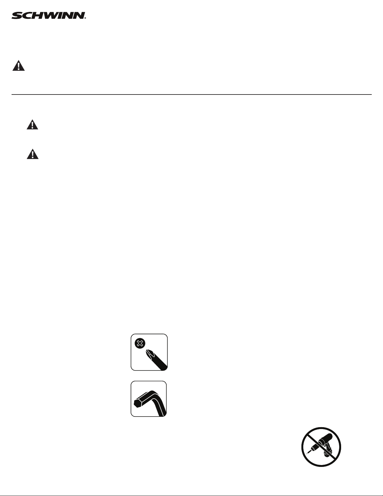
Note: Your machine may not match the image. For reference only.
1. Unplug the AC Adapter from the wall outlet and machine.
2. Loosen and remove the hardware that attaches Console/Mast As-
sembly to the frame. Set the hardware safely aside for reassembly.
NOTICE: Hold the Console/Mast Assembly so that it does not fall.
This step may require two people.
3. Carefully lift the Console/Mast Assembly and disconnect the cables.
Tie the piece of string to the ends of the cables at the base of the Mast.
NOTICE: Do not let the cables fall down inside the frame. This step
may require two people.
22
4. Loosen and remove the screws that attach the Console to the Mast
and Water Bottle Holder. Set the screws safely aside.
NOTICE: Hold the Console so that it does not fall. This step may
require two people.
5. Remove the Console and pull the cables out of the Mast tube so that
the string extends through the tube. Untie the string from the cables.
6. Tie the string end at the top of the Mast to the ends of the cables on
the replacement Console. Carefully pull the cables through the Mast tube.
NOTICE: Do not crimp any cables.
7. Install the replacement Console to the Mast. Untie the string from the
cables.
NOTICE: Do not crimp any cables. Hold the Console so that it does
not fall. This step may require two people.
8. Connect the cables from the Mast and frame, and install the Console/
Mast assembly to the frame.
NOTICE: Do not crimp any cables. This step may require two people.
9. Discard the old parts.
10. Inspect your machine to ensure that all hardware is tight and
components are properly assembled.
Do not use until the machine has been fully assembled and
inspected for correct performance in accordance with the
Owner’s Manual.
23
Replace the Console Mast
on the Schwinn® AD7 AirDyne® Bike Skill Level: II
8014193.021522.C
Replacement Procedure
NOTICE: This document provides instructions for the replacement of the Console Mast on the Schwinn® AD7 AirDyne® Bikes.
If you need assistance, please call Schwinn Customer Service (if purchased in US/Canada) or your local distributor (if purchased out-
side US/Canada). To nd your local distributor, go to: www.nautilusinternational.com
This icon means a potentially hazardous situation which, if not avoided, could result in death or serious injury. Read and understand
all Warnings on this machine.
Tools Required (not included)
#2 Phillips screwdriver
6mm hex key
3’ (91 cm) length of string
Important Safety Instructions
This icon means a potentially hazardous situation which, if not avoided, could result in death or serious injury. Read and
understand all Warnings on this machine.
Before servicing or using this equipment, obey the following warnings:
Read and understand the Service Manual before working on the machine. Failure to obey the instructions and safety warnings
could cause injury to the service technician or bystanders.
• Keep bystanders and children away from the product being serviced at all times.
• Makesurethattherepairisdoneinanappropriateworkspaceawayfromfoottrafcandexposuretobystanders.
• Disconnect all power to the machine before you service it.
• Some components of the equipment can be heavy or awkward. Enlist the service of a second person when you do maintenance steps involving
these components. Do not try to do heavy or awkward steps on your own.
• If replacement parts are necessary, use only genuine replacement parts and hardware supplied by Nautilus. Failure to use genuine replacement
parts can cause a risk to users, keep the machine from operating correctly and void the warranty.
• Be sure that all warning stickers and instructional placards applied to the product stay present and in good condition when doing maintenance or
replacing components. If at any time the Warning labels become loose, unreadable or dislodged, replace the labels. If purchased in US/Canada,
contact Customer Service for replacement labels. If purchased outside US/Canada, contact your local distributor for them..
• Do not try to change the design or functionality of the machine being serviced as this can adversely affect user safety.
• Donotputthemachinebackinserviceuntilallshrouds,instructions,warninglabelsandcorrectfunctionalityhavebeenveriedandtestedfor
correct performance.
• SAVE THESE INSTRUCTIONS.
Nautilus, Inc., www.NautilusInc.com, 5415 Centerpoint Parkway, Groveport, OH 43125 U.S.A. - Customer Service: North America (800) 605-3369, [email protected] | outside U.S. www.nautilusinternational.com | © 2016
Nautilus, Inc. | Schwinn, the Schwinn Quality logo, and AirDyne are trademarks owned by or licensed to Nautilus, Inc., which are registered or otherwise protected by common law in the United States and other countries.
Polar® is a registered trademarks of its owner. | ORIGINAL DOCUMENT - ENGLISH VERSION ONLY
24
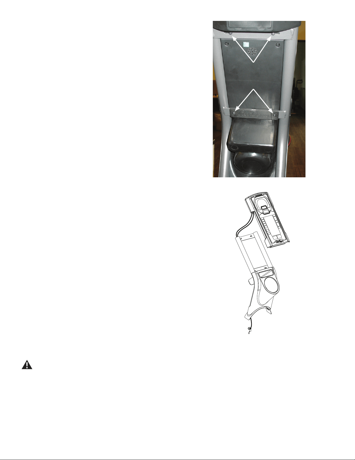
Note: Your machine may not match the image. For reference only.
1. Unplug the AC Adapter from the wall outlet and machine.
2. Loosen and remove the hardware that attaches Console/Mast As-
sembly to the frame. Set the hardware safely aside for reassembly.
NOTICE: Hold the Console/Mast Assembly so that it does not fall.
This step may require two people.
3. Carefully lift the Console/Mast Assembly and disconnect the cables.
NOTICE: Do not let the cables fall down inside the frame. This step
may require two people.
25
4. Loosen and remove the screws that attach the Console to the Mast
and Water Bottle Holder. Set the screws safely aside.
NOTICE: Hold the Console so that it does not fall. This step may
require two people.
5. Carefully remove the Console and pull the cables out of the Mast
tube. Set it safely aside.
NOTICE: Do not crimp any cables.
6. Remove the Water Bottle Holder from the Mast. Set it safely aside.
7. Put the Water Bottle Holder in position on the replacement Mast.
8. Tie one end of the piece of string to the Console cable connectors.
Tie the other end to one of the screws from step 1. Use the weight of the
screw to route the cables through the replacement Mast tube.
NOTICE: Do not crimp any cables. Hold the Console so that it does
not fall. This step may require two people.
9. Install the replacement Console to the Mast. Untie the string from
the cables and screw. Connect the cables from the Mast and frame, and
install the Console/Mast assembly to the frame.
NOTICE: Do not crimp any cables. Hold the Console so that it does
not fall. This step may require two people.
10. Discard the old parts.
11. Inspect your machine to ensure that all hardware is tight and
components are properly assembled.
Do not use until the machine has been fully assembled and
inspected for correct performance in accordance with the
Owner’s Manual.

26
Replace the Transport Wheels on the
Schwinn® AD7 AirDyne® Bike Skill Level: I
8014194.021522.C
Replacement Procedure
NOTICE: This document provides instructions for the replacement of the Transport Wheels on the Schwinn® AD7 AirDyne® Bike.
If you need assistance, please call Schwinn Customer Service (if purchased in US/Canada) or your local distributor (if purchased out-
side US/Canada). To nd your local distributor, go to: www.nautilusinternational.com
This icon means a potentially hazardous situation which, if not avoided, could result in death or serious injury. Read and understand
all Warnings on this machine.
Tools Required (not included)
13mm open end wrench (2)
Important Safety Instructions
This icon means a potentially hazardous situation which, if not avoided, could result in death or serious injury. Read and
understand all Warnings on this machine.
Before servicing or using this equipment, obey the following warnings:
Read and understand the Service Manual before working on the machine. Failure to obey the instructions and safety warnings
could cause injury to the service technician or bystanders.
• Keep bystanders and children away from the product being serviced at all times.
• Makesurethattherepairisdoneinanappropriateworkspaceawayfromfoottrafcandexposuretobystanders.
• Disconnect all power to the machine before you service it.
• Some components of the equipment can be heavy or awkward. Enlist the service of a second person when you do maintenance steps involving
these components. Do not try to do heavy or awkward steps on your own.
• If replacement parts are necessary, use only genuine replacement parts and hardware supplied by Nautilus. Failure to use genuine replacement
parts can cause a risk to users, keep the machine from operating correctly and void the warranty.
• Be sure that all warning stickers and instructional placards applied to the product stay present and in good condition when doing maintenance or
replacing components. If at any time the Warning labels become loose, unreadable or dislodged, replace the labels. If purchased in US/Canada,
contact Customer Service for replacement labels. If purchased outside US/Canada, contact your local distributor for them..
• Do not try to change the design or functionality of the machine being serviced as this can adversely affect user safety.
• Donotputthemachinebackinserviceuntilallshrouds,instructions,warninglabelsandcorrectfunctionalityhavebeenveriedandtestedfor
correct performance.
• SAVE THESE INSTRUCTIONS.
Nautilus, Inc., www.NautilusInc.com, 5415 Centerpoint Parkway, Groveport, OH 43125 U.S.A. - Customer Service: North America (800) 605-3369, [email protected] | outside U.S. www.nautilusinternational.com | © 2016
Nautilus, Inc. | Schwinn, the Schwinn Quality logo, and AirDyne are trademarks owned by or licensed to Nautilus, Inc., which are registered or otherwise protected by common law in the United States and other countries.
Polar® is a registered trademarks of its owner. | ORIGINAL DOCUMENT - ENGLISH VERSION ONLY
27
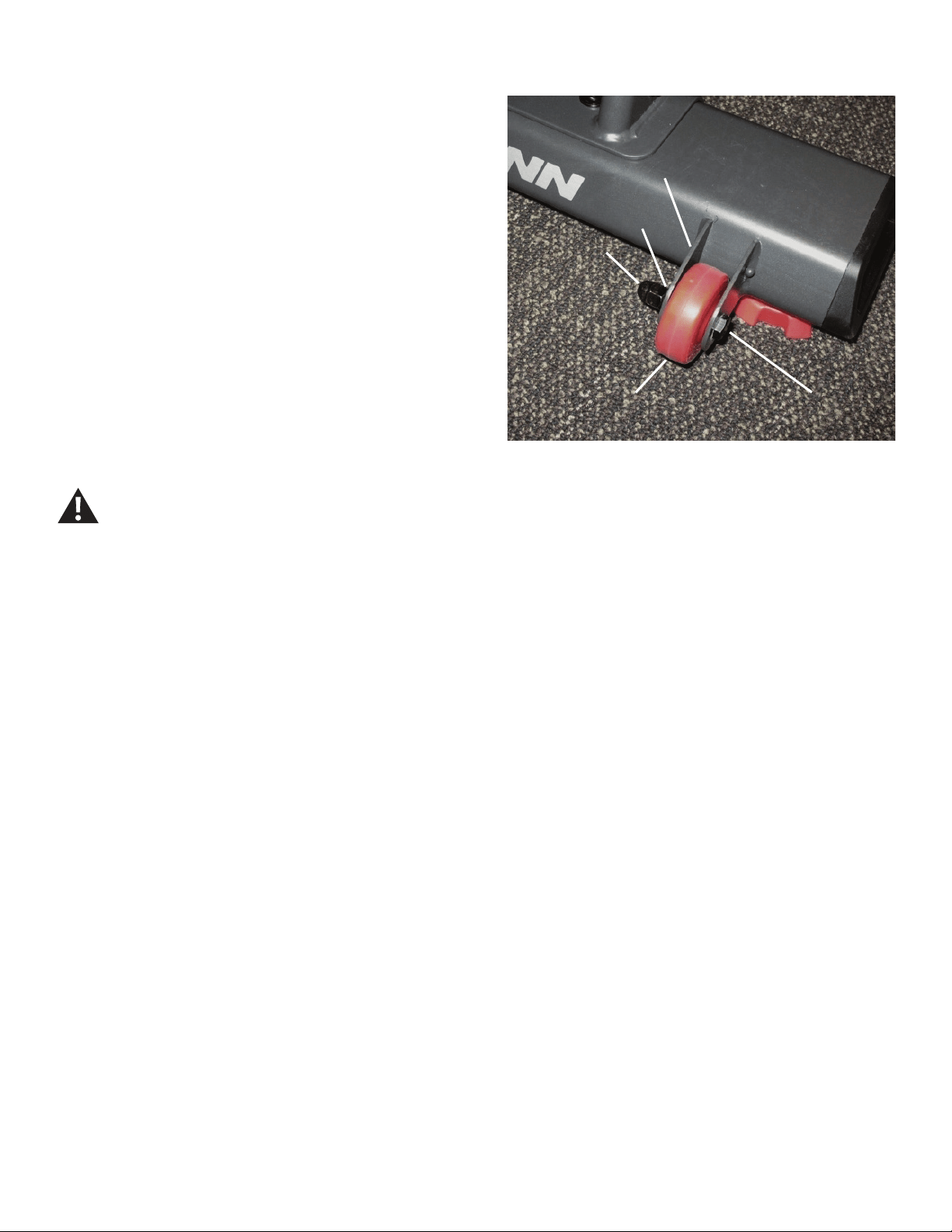
Note: Your machine may not match the image. For reference only.
1. Using the 13mm wrenches, loosen and remove the hex head bolt (A),
acorn nut (B) and lock washer (C) from the old Transport Wheel assembly.
Remove the old Transport Wheel (D) from the bracket (E), and discard.
2. Install the replacement Transport Wheel assembly.
NOTICE: Be sure that the Transport Wheel can turn freely.
3. Final Inspection
Inspect your machine to ensure that all hardware is tight and components
are properly assembled.
Do not use until the machine has been fully assembled and
inspected for correct performance in accordance with the
Owner’s Manual.
AA
CC
BB
EE
DD

28
Replace the Levelers on the Schwinn® AD7 AirDyne® Bike
Skill Level: I
8014195.021522.C
Replacement Procedure
NOTICE: This document provides instructions for the replacement of the Levelers on the Schwinn® AD7 AirDyne® Bike.
If you need assistance, please call Schwinn Customer Service (if purchased in US/Canada) or your local distributor (if purchased out-
side US/Canada). To nd your local distributor, go to: www.nautilusinternational.com
This icon means a potentially hazardous situation which, if not avoided, could result in death or serious injury. Read and understand
all Warnings on this machine.
Tools Required (not included)
13mm open end wrench
Static solid object (like a book or box)
Important Safety Instructions
This icon means a potentially hazardous situation which, if not avoided, could result in death or serious injury. Read and
understand all Warnings on this machine.
Before servicing or using this equipment, obey the following warnings:
Read and understand the Service Manual before working on the machine. Failure to obey the instructions and safety warnings
could cause injury to the service technician or bystanders.
• Keep bystanders and children away from the product being serviced at all times.
• Makesurethattherepairisdoneinanappropriateworkspaceawayfromfoottrafcandexposuretobystanders.
• Disconnect all power to the machine before you service it.
• Some components of the equipment can be heavy or awkward. Enlist the service of a second person when you do maintenance steps involving
these components. Do not try to do heavy or awkward steps on your own.
• If replacement parts are necessary, use only genuine replacement parts and hardware supplied by Nautilus. Failure to use genuine replacement
parts can cause a risk to users, keep the machine from operating correctly and void the warranty.
• Be sure that all warning stickers and instructional placards applied to the product stay present and in good condition when doing maintenance or
replacing components. If at any time the Warning labels become loose, unreadable or dislodged, replace the labels. If purchased in US/Canada,
contact Customer Service for replacement labels. If purchased outside US/Canada, contact your local distributor for them..
• Do not try to change the design or functionality of the machine being serviced as this can adversely affect user safety.
• Donotputthemachinebackinserviceuntilallshrouds,instructions,warninglabelsandcorrectfunctionalityhavebeenveriedandtestedfor
correct performance.
• SAVE THESE INSTRUCTIONS.
Nautilus, Inc., www.NautilusInc.com, 5415 Centerpoint Parkway, Groveport, OH 43125 U.S.A. - Customer Service: North America (800) 605-3369, [email protected] | outside U.S. www.nautilusinternational.com | © 2016
Nautilus, Inc. | Schwinn, the Schwinn Quality logo, and AirDyne are trademarks owned by or licensed to Nautilus, Inc., which are registered or otherwise protected by common law in the United States and other countries.
Polar® is a registered trademarks of its owner. | ORIGINAL DOCUMENT - ENGLISH VERSION ONLY
29
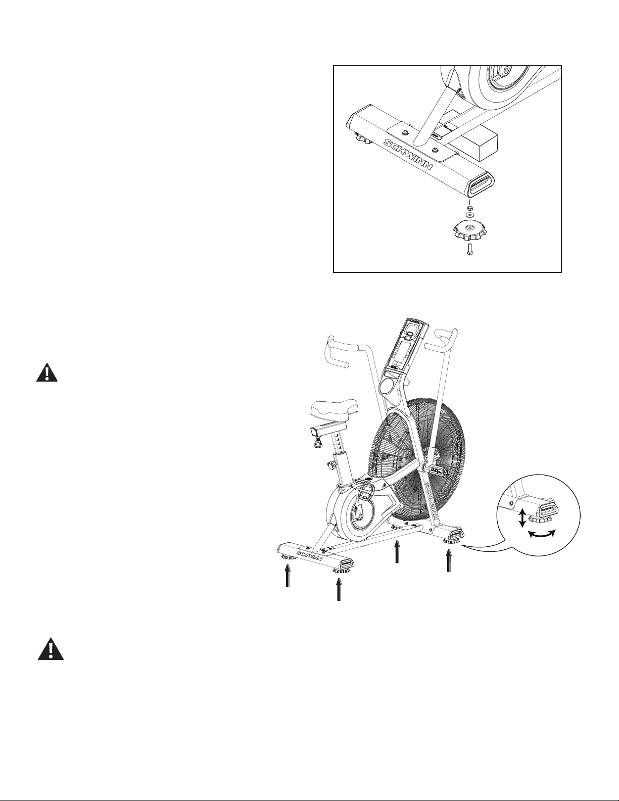
Note: Your machine may not match the image. For reference only.
1. Place a static object (like a book or box) under the main frame near
the Stabilizer. The static object should not be compressible.
2. Using the 13mm wrench, loosen and remove the hex head bolt from
the old Leveler. Remove the Leveler foot and hardware from the Stabilizer,
and discard.
3. Install the replacement Leveler assembly. Hand tighten the hardware.
Turn the stabilizer feet to adjust until they are evenly balanced
andincontactwiththeoor.
Do not adjust the levelers to such a height that they
detach or unscrew from the machine. Injury to you or
damage to the machine can occur.
Make sure the machine is level and stable before you exercise.
4. Final Inspection
Inspect your machine to ensure that all hardware is tight and
components are properly assembled.
Do not use until the machine has been fully assembled and
inspected for correct performance in accordance with the
Owner’s Manual.
30
Replace the Seat Post on the Schwinn® AD7 AirDyne® Bike
Skill Level: I
8014196.021522.C
Replacement Procedure
NOTICE: This document provides instructions for the replacement of the Seat Post on the Schwinn® AD7 AirDyne® Bike.
If you need assistance, please call Schwinn Customer Service (if purchased in US/Canada) or your local distributor (if purchased out-
side US/Canada). To nd your local distributor, go to: www.nautilusinternational.com
This icon means a potentially hazardous situation which, if not avoided, could result in death or serious injury. Read and understand
all Warnings on this machine.
Tools Required (not included)
13mm open end wrench
Important Safety Instructions
This icon means a potentially hazardous situation which, if not avoided, could result in death or serious injury. Read and
understand all Warnings on this machine.
Before servicing or using this equipment, obey the following warnings:
Read and understand the Service Manual before working on the machine. Failure to obey the instructions and safety warnings
could cause injury to the service technician or bystanders.
• Keep bystanders and children away from the product being serviced at all times.
• Makesurethattherepairisdoneinanappropriateworkspaceawayfromfoottrafcandexposuretobystanders.
• Disconnect all power to the machine before you service it.
• Some components of the equipment can be heavy or awkward. Enlist the service of a second person when you do maintenance steps involving
these components. Do not try to do heavy or awkward steps on your own.
• If replacement parts are necessary, use only genuine replacement parts and hardware supplied by Nautilus. Failure to use genuine replacement
parts can cause a risk to users, keep the machine from operating correctly and void the warranty.
• Be sure that all warning stickers and instructional placards applied to the product stay present and in good condition when doing maintenance or
replacing components. If at any time the Warning labels become loose, unreadable or dislodged, replace the labels. If purchased in US/Canada,
contact Customer Service for replacement labels. If purchased outside US/Canada, contact your local distributor for them..
• Do not try to change the design or functionality of the machine being serviced as this can adversely affect user safety.
• Donotputthemachinebackinserviceuntilallshrouds,instructions,warninglabelsandcorrectfunctionalityhavebeenveriedandtestedfor
correct performance.
• SAVE THESE INSTRUCTIONS.
Nautilus, Inc., www.NautilusInc.com, 5415 Centerpoint Parkway, Groveport, OH 43125 U.S.A. - Customer Service: North America (800) 605-3369, [email protected] | outside U.S. www.nautilusinternational.com | © 2016
Nautilus, Inc. | Schwinn, the Schwinn Quality logo, and AirDyne are trademarks owned by or licensed to Nautilus, Inc., which are registered or otherwise protected by common law in the United States and other countries.
Polar® is a registered trademarks of its owner. | ORIGINAL DOCUMENT - ENGLISH VERSION ONLY
31
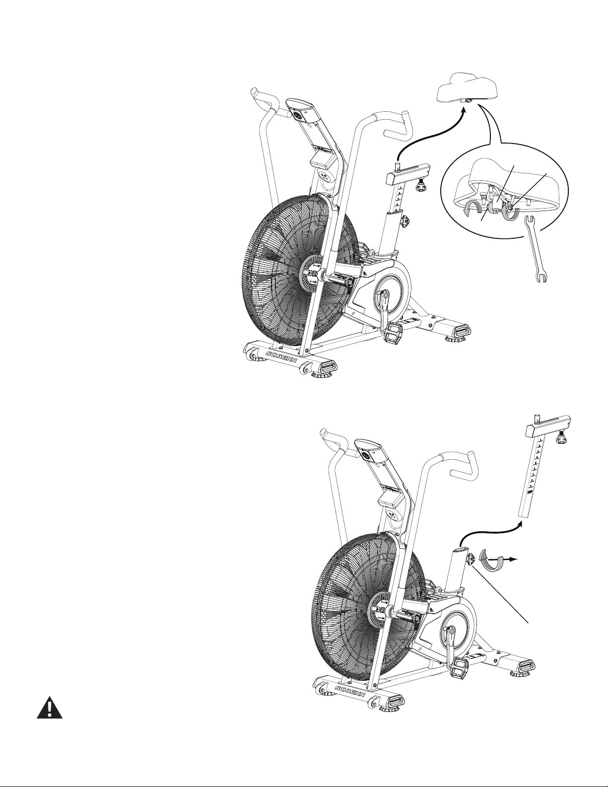
Note: Your machine may not match the image. For reference only.
1. Using the 13mm wrench, loosen the Nuts (B) on the Seat bracket (A).
2. Remove the Seat from the Seat Post and set it
safely aside for reassembly.
3. Loosen and pull the Seat Post Adjustment Knob (C), and remove the
Seat Post. Set it safely aside.
NOTICE: This step may require two people.
4. Install the replacement Seat Post on the frame. Release the Seat
Post Adjustment Knob (C) to engage the locking pin. Be sure that the pin
is fully engaged and fully tighten the adjustment knob.
5. Attach the Seat to the Seat Post.
NOTICE: Be sure the Seat is straight and level. Tighten both nuts
(B) on the Seat bracket (A) to hold the Seat in position.
6. Final Inspection
Inspect your machine to ensure that all hardware is tight and components
are properly assembled.
Do not use until the machine has been fully assembled and
inspected for correct performance in accordance with the
Owner’s Manual.
A
B
B
C
32
Replace the Handlebar Arms and Foot Pegs
on the Schwinn® AD7 AirDyne® Bike Skill Level: II
8014197.021522.C
Replacement Procedure
NOTICE: This document provides instructions for the replacement of the Handlebar Arms and Foot Pegs on the Schwinn® AD7 AirDyne® Bike.
If you need assistance, please call Schwinn Customer Service (if purchased in US/Canada) or your local distributor (if purchased out-
side US/Canada). To nd your local distributor, go to: www.nautilusinternational.com
This icon means a potentially hazardous situation which, if not avoided, could result in death or serious injury. Read and understand
all Warnings on this machine.
Tools Required (not included)
6mm hex key
6mm calibrated torque wrench (40 N.m)
Important Safety Instructions
This icon means a potentially hazardous situation which, if not avoided, could result in death or serious injury. Read and
understand all Warnings on this machine.
Before servicing or using this equipment, obey the following warnings:
Read and understand the Service Manual before working on the machine. Failure to obey the instructions and safety warnings
could cause injury to the service technician or bystanders.
• Keep bystanders and children away from the product being serviced at all times.
• Makesurethattherepairisdoneinanappropriateworkspaceawayfromfoottrafcandexposuretobystanders.
• Disconnect all power to the machine before you service it.
• Some components of the equipment can be heavy or awkward. Enlist the service of a second person when you do maintenance steps involving
these components. Do not try to do heavy or awkward steps on your own.
• If replacement parts are necessary, use only genuine replacement parts and hardware supplied by Nautilus. Failure to use genuine replacement
parts can cause a risk to users, keep the machine from operating correctly and void the warranty.
• Be sure that all warning stickers and instructional placards applied to the product stay present and in good condition when doing maintenance or
replacing components. If at any time the Warning labels become loose, unreadable or dislodged, replace the labels. If purchased in US/Canada,
contact Customer Service for replacement labels. If purchased outside US/Canada, contact your local distributor for them..
• Do not try to change the design or functionality of the machine being serviced as this can adversely affect user safety.
• Donotputthemachinebackinserviceuntilallshrouds,instructions,warninglabelsandcorrectfunctionalityhavebeenveriedandtestedfor
correct performance.
• SAVE THESE INSTRUCTIONS.
Nautilus, Inc., www.NautilusInc.com, 5415 Centerpoint Parkway, Groveport, OH 43125 U.S.A. - Customer Service: North America (800) 605-3369, [email protected] | outside U.S. www.nautilusinternational.com | © 2016
Nautilus, Inc. | Schwinn, the Schwinn Quality logo, and AirDyne are trademarks owned by or licensed to Nautilus, Inc., which are registered or otherwise protected by common law in the United States and other countries.
Polar® is a registered trademarks of its owner. | ORIGINAL DOCUMENT - ENGLISH VERSION ONLY
33
Note: Your machine may not match the image. For reference only.
1. Loosen the hardware that attaches Foot Peg to the frame
assembly. Remove the hardware and Foot Peg, and set them safely
aside.
If you are only replacing the Foot Peg, go to step 4.
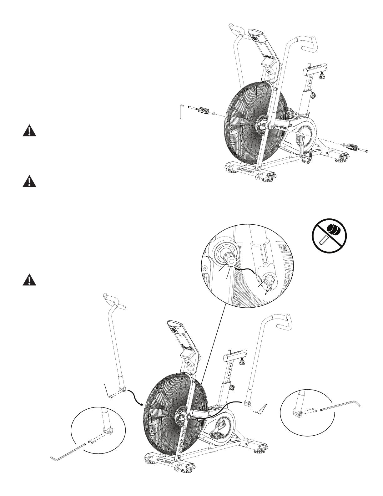
2. Loosen and remove the screws (A) that attach the Handlebar
Arm to the Arm Pivot assembly. Set them safely aside.
Be aware that the Pedals, Handlebars and Resistance
Fan are connected and when any of these parts move
the others do as well.
3. Remove the Handlebar Arm and set it safely aside.
Do not use a hammer to remove or install the
handlebars.
4. Installation is the reverse procedure.
NOTICE: Remove tag from the Handlebar Arm. Align the
open curve (a) on the handlebar with the smooth curve
(1a) on the pivot shaft and make sure the indents (b) are
exactly aligned. Carefully push the handlebar onto the
shaft. Do not force or hammer into position. Gently rock
the handlebar forward and backward to make sure it is
fully seated on the shaft.
Fully tighten the Cap Screws (A) on the Handlebar Arm or
torque to 40 N.m.
6mm
A
A6mm
1a
b
a
b
A
6mm
A X2

34
NOTICE: Push the Shoulder Screw completely through the
Foot Peg, and press the Washer tightly onto the end of
the Foot Peg. Be sure the Washer does not touch the
bolt threads. Do not let the Washer fall off the Foot Peg
during installation.
Fully tighten hardware. Make sure the Handlebar Arms are
secure before you exercise.
5. Set the old parts safely aside.
6. Final Inspection
Inspect your machine to ensure that all hardware is tight and components
are properly assembled.
Do not use until the machine has been fully assembled and
inspected for correct performance in accordance with the
Owner’s Manual.
35
Replace the Crank Arm Assembly
on the Schwinn® AD7 AirDyne® Bike Skill Level: II
8014198.021522.C
Replacement Procedure
NOTICE: This document provides instructions for the replacement of the Crank Arms on the Schwinn® AD7 AirDyne® Bike.
If you need assistance, please call Schwinn Customer Service (if purchased in US/Canada) or your local distributor (if purchased out-
side US/Canada). To nd your local distributor, go to: www.nautilusinternational.com
This icon means a potentially hazardous situation which, if not avoided, could result in death or serious injury. Read and understand
all Warnings on this machine.
Tools Required (not included)
Pedal wrench 8mm calibrated torque wrench (60 N.m)
or 15 mm open end wrench
8mm hex key
Important Safety Instructions
This icon means a potentially hazardous situation which, if not avoided, could result in death or serious injury. Read and
understand all Warnings on this machine.
Before servicing or using this equipment, obey the following warnings:
Read and understand the Service Manual before working on the machine. Failure to obey the instructions and safety warnings
could cause injury to the service technician or bystanders.
• Keep bystanders and children away from the product being serviced at all times.
• Makesurethattherepairisdoneinanappropriateworkspaceawayfromfoottrafcandexposuretobystanders.
• Disconnect all power to the machine before you service it.
• Some components of the equipment can be heavy or awkward. Enlist the service of a second person when you do maintenance steps involving
these components. Do not try to do heavy or awkward steps on your own.
• If replacement parts are necessary, use only genuine replacement parts and hardware supplied by Nautilus. Failure to use genuine replacement
parts can cause a risk to users, keep the machine from operating correctly and void the warranty.
• Be sure that all warning stickers and instructional placards applied to the product stay present and in good condition when doing maintenance or
replacing components. If at any time the Warning labels become loose, unreadable or dislodged, replace the labels. If purchased in US/Canada,
contact Customer Service for replacement labels. If purchased outside US/Canada, contact your local distributor for them..
• Do not try to change the design or functionality of the machine being serviced as this can adversely affect user safety.
• Donotputthemachinebackinserviceuntilallshrouds,instructions,warninglabelsandcorrectfunctionalityhavebeenveriedandtestedfor
correct performance.
• SAVE THESE INSTRUCTIONS.
Nautilus, Inc., www.NautilusInc.com, 5415 Centerpoint Parkway, Groveport, OH 43125 U.S.A. - Customer Service: North America (800) 605-3369, [email protected] | outside U.S. www.nautilusinternational.com | © 2016
Nautilus, Inc. | Schwinn, the Schwinn Quality logo, and AirDyne are trademarks owned by or licensed to Nautilus, Inc., which are registered or otherwise protected by common law in the United States and other countries.
Polar® is a registered trademarks of its owner. | ORIGINAL DOCUMENT - ENGLISH VERSION ONLY
36
Note: Your machine may not match the image. For reference only.
1. Unplug the AC Adapter from the wall outlet and machine.
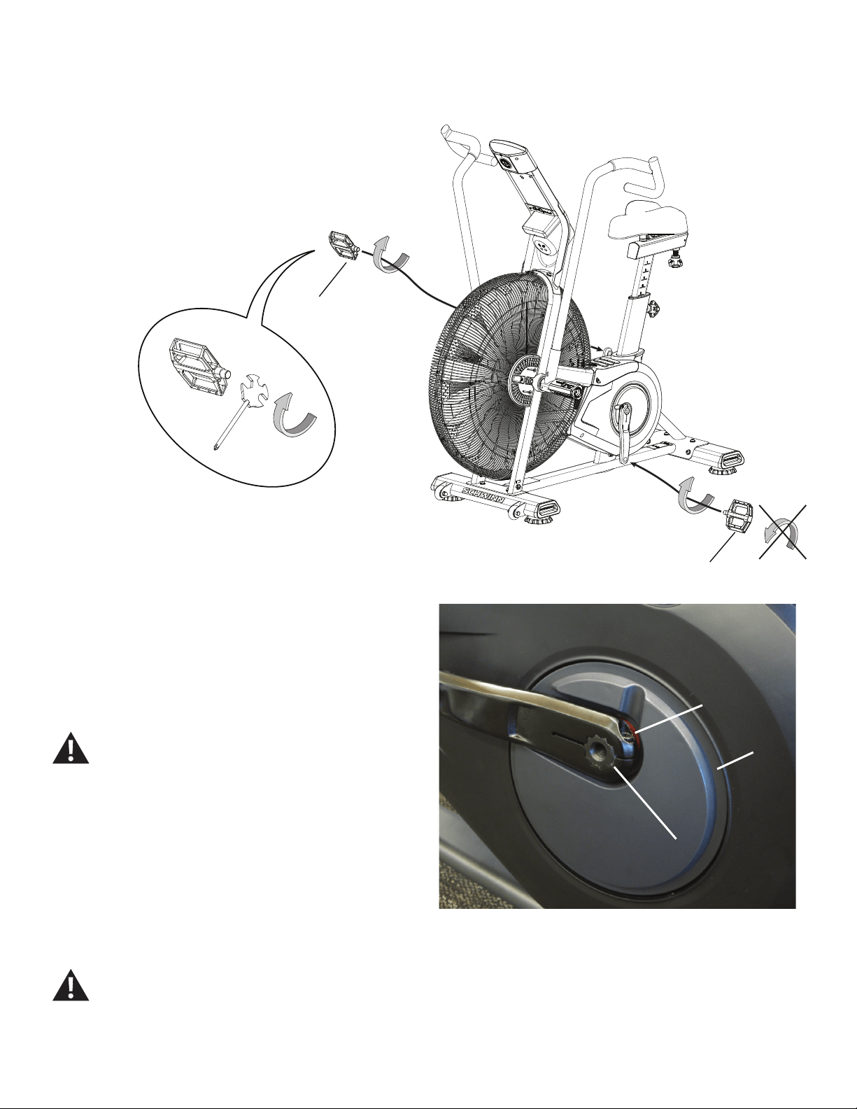
2. Loosen and remove the Pedals. Set them safely aside for
reassembly.
Note: The Left Pedal is reverse-threaded. Orientation is based
from a seated position on the bike. The Left Pedal has an “L”,
the Right Pedal an “R”.
3. Using an 8mm hex key, remove the Cap Screw from the Crank Arm
assembly (B).
NOTICE: Hold the Crank Arm assembly so that it does not fall.
4. Remove the Crank Arm assembly (B) from the Crank Assembly shaft
(C). Set it safely aside.
5. Installation is the reverse procedure.
Using an 8mm hex key, completely tighten the new Cap Screws (A) on the
replacement Crank Arms, or torque to 60 N.m.
The Left Crank Arm has an “L”, the Right Crank Arm an “R.
Orientation is based from a seated position on the bike.
Make sure the Crank Arms are secure before you exercise.
To reinstall the Pedals, carefully align the threads and hand tighten to
prevent cross-threading. Then tighten fully with pedal wrench.
Note: The Left Pedal is reverse-threaded. Be sure to attach
Pedals on the correct side of the Bike. Orientation is based from a seated
position on the bike. The Left Pedal has an “L”, the Right Pedal an “R”.
6. Final Inspection
Inspect your machine to ensure that all hardware is tight and components
are properly assembled.
Do not use until the machine has been fully assembled and
inspected for correct performance in accordance with the
Owner’s Manual.
(L)
(R)
AA
CC
BB
(60 N.m)
37
Replace the Shrouds and Footpad
on the Schwinn® AD7 AirDyne® Bike Skill Level: II
8014199.021522.C
Replacement Procedure
NOTICE: This document provides instructions for the replacement of the side Shrouds and Top Shroud/Footpad on the Schwinn® AD7 AirDyne® Bike.
If you need assistance, please call Schwinn Customer Service (if purchased in US/Canada) or your local distributor (if purchased out-
side US/Canada). To nd your local distributor, go to: www.nautilusinternational.com
This icon means a potentially hazardous situation which, if not avoided, could result in death or serious injury. Read and understand
all Warnings on this machine.
Tools Required (not included)
#2 Phillips screwdriver
Important Safety Instructions
This icon means a potentially hazardous situation which, if not avoided, could result in death or serious injury. Read and
understand all Warnings on this machine.
Before servicing or using this equipment, obey the following warnings:
Read and understand the Service Manual before working on the machine. Failure to obey the instructions and safety warnings
could cause injury to the service technician or bystanders.
• Keep bystanders and children away from the product being serviced at all times.
• Makesurethattherepairisdoneinanappropriateworkspaceawayfromfoottrafcandexposuretobystanders.
• Disconnect all power to the machine before you service it.
• Some components of the equipment can be heavy or awkward. Enlist the service of a second person when you do maintenance steps involving
these components. Do not try to do heavy or awkward steps on your own.
• If replacement parts are necessary, use only genuine replacement parts and hardware supplied by Nautilus. Failure to use genuine replacement
parts can cause a risk to users, keep the machine from operating correctly and void the warranty.
• Be sure that all warning stickers and instructional placards applied to the product stay present and in good condition when doing maintenance or
replacing components. If at any time the Warning labels become loose, unreadable or dislodged, replace the labels. If purchased in US/Canada,
contact Customer Service for replacement labels. If purchased outside US/Canada, contact your local distributor for them..
• Do not try to change the design or functionality of the machine being serviced as this can adversely affect user safety.
• Donotputthemachinebackinserviceuntilallshrouds,instructions,warninglabelsandcorrectfunctionalityhavebeenveriedandtestedfor
correct performance.
• SAVE THESE INSTRUCTIONS.
Nautilus, Inc., www.NautilusInc.com, 5415 Centerpoint Parkway, Groveport, OH 43125 U.S.A. - Customer Service: North America (800) 605-3369, [email protected] | outside U.S. www.nautilusinternational.com | © 2016
Nautilus, Inc. | Schwinn, the Schwinn Quality logo, and AirDyne are trademarks owned by or licensed to Nautilus, Inc., which are registered or otherwise protected by common law in the United States and other countries.
Polar® is a registered trademarks of its owner. | ORIGINAL DOCUMENT - ENGLISH VERSION ONLY
38
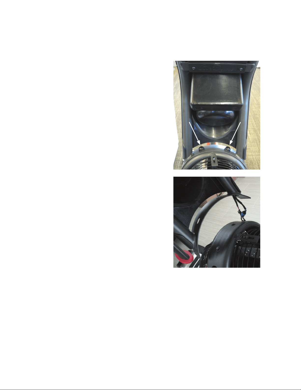
Note: Your machine may not match the image. For reference only.
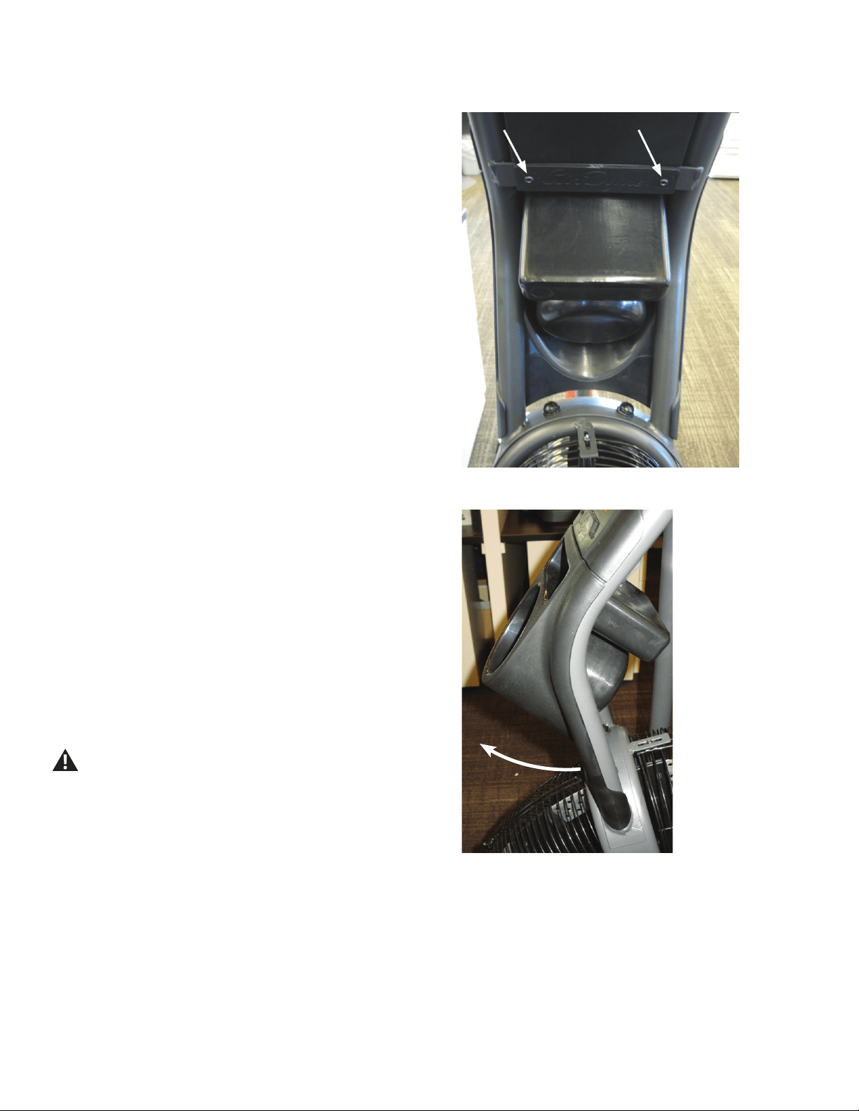
1. Unplug the AC Adapter from the wall outlet and machine.
2. Slide the Grommet up the Seat Post to expose the screws that attach
the Top Shroud to the frame.
Note: If necessary, remove the Seat Post and the Seat Adjustment
Knob (A). Set them safely aside for reassembly. Remove the
Grommet and set it safely aside for reassembly.
3. Using a #2 Phillips Screwdriver, loosen and remove the 4 screws
(indicated) from the Top Shroud, and set them safely aside for reassembly.
4. Remove the Top Shroud and set it safely aside.
6. Turn the Right Crank Arm to point toward the back of the machine.
Using a #2 Phillips Screwdriver, remove the 5 screws (indicated) that
securetheRightShroud.Removethebottomscrewsrstandthenthetop
screws.
6. Slowly remove the Right Shroud.
7. Turn the Left Crank Arm to point toward the back of the machine.
Using a #2 Phillips Screwdriver, remove the 3 screws that secure the Left
Shroud.Removethebottomscrewsrstandthenthetopscrews.Slowly
remove the Left Shroud.
8. Installation is the reverse procedure. Put the Right Shroud in position
rsttoalignthescrewsfortheLeftShroud.Installthetopscrewsrst.
NOTICE: Be sure the tabs in the Top Shroud snap into the Main
Assembly.
9. Final Inspection
Inspect your machine to ensure that all hardware is tight and compo-
nents are properly assembled.
Do not use until the machine has been fully assembled and
inspected for correct performance in accordance with the
Owner’s Manual.
Crank arms not shown
X2
A
39
Replace the Fan Cage on the Schwinn® AD7 AirDyne® Bike
Skill Level: I
8014200.021522.C
Replacement Procedure
NOTICE: This document provides instructions for the replacement of the Fan Cage on the Schwinn® AD7 AirDyne® Bike.
If you need assistance, please call Schwinn Customer Service (if purchased in US/Canada) or your local distributor (if purchased out-
side US/Canada). To nd your local distributor, go to: www.nautilusinternational.com
This icon means a potentially hazardous situation which, if not avoided, could result in death or serious injury. Read and understand
all Warnings on this machine.
Tools Required (not included)
#2 Phillips screwdriver
Important Safety Instructions
This icon means a potentially hazardous situation which, if not avoided, could result in death or serious injury. Read and
understand all Warnings on this machine.
Before servicing or using this equipment, obey the following warnings:
Read and understand the Service Manual before working on the machine. Failure to obey the instructions and safety warnings
could cause injury to the service technician or bystanders.
• Keep bystanders and children away from the product being serviced at all times.
• Makesurethattherepairisdoneinanappropriateworkspaceawayfromfoottrafcandexposuretobystanders.
• Disconnect all power to the machine before you service it.
• Some components of the equipment can be heavy or awkward. Enlist the service of a second person when you do maintenance steps involving
these components. Do not try to do heavy or awkward steps on your own.
• If replacement parts are necessary, use only genuine replacement parts and hardware supplied by Nautilus. Failure to use genuine replacement
parts can cause a risk to users, keep the machine from operating correctly and void the warranty.
• Be sure that all warning stickers and instructional placards applied to the product stay present and in good condition when doing maintenance or
replacing components. If at any time the Warning labels become loose, unreadable or dislodged, replace the labels. If purchased in US/Canada,
contact Customer Service for replacement labels. If purchased outside US/Canada, contact your local distributor for them..
• Do not try to change the design or functionality of the machine being serviced as this can adversely affect user safety.
• Donotputthemachinebackinserviceuntilallshrouds,instructions,warninglabelsandcorrectfunctionalityhavebeenveriedandtestedfor
correct performance.
• SAVE THESE INSTRUCTIONS.
Nautilus, Inc., www.NautilusInc.com, 5415 Centerpoint Parkway, Groveport, OH 43125 U.S.A. - Customer Service: North America (800) 605-3369, [email protected] | outside U.S. www.nautilusinternational.com | © 2016
Nautilus, Inc. | Schwinn, the Schwinn Quality logo, and AirDyne are trademarks owned by or licensed to Nautilus, Inc., which are registered or otherwise protected by common law in the United States and other countries.
Polar® is a registered trademarks of its owner. | ORIGINAL DOCUMENT - ENGLISH VERSION ONLY
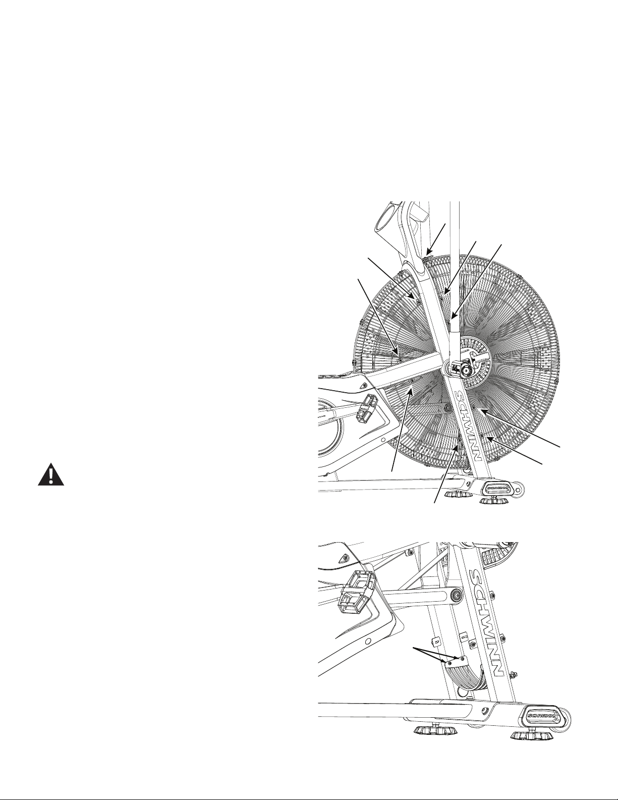
40
Note: Your machine may not match the image. For reference only.
1. Unplug the AC Adapter from the wall outlet and machine.
To remove the lower back Fan Cage sections, it is necessary to
remove the Shrouds. Refer to the “Replace the Shrouds” procedure.
To remove the upper back Fan Cage sections, if an Air Diverter is
installed, it is necessary to remove the Air Diverter rst.
2. Using a #2 Phillips Screwdriver, loosen and remove the screws that
attach each section of the Fan Cage to the frame, and carefully remove
thesection.Removethebottomscrewsrstandthenthetopscrews.Set
them safely aside for reassembly.
NOTICE: Hold each section of the Fan Cage as you loosen the
screws so that it does not fall. If necessary, loosen and
remove the screws and clips that attach the sections of the
Fan Cage to each other.
3. Installation is the reverse procedure.
NOTICE: This step may require two people.
4. Final Inspection
Inspect your machine to ensure that all hardware is tight and components
are properly assembled.
Do not use until the machine has been fully assembled and
inspected for correct performance in accordance with the
Owner’s Manual.
X2
NOTICE: It is necessary to remove the Shrouds for this procedure. Refer to the “Replace the Shrouds” procedure.
41
Replace the Linkage Arms
on the Schwinn® AD7 AirDyne® Bike Skill Level: II
8014201.021522.C
Replacement Procedure
NOTICE: This document provides instructions for the replacement of the Linkage Arms on the Schwinn® AD7 AirDyne® Bike.
If you need assistance, please call Schwinn Customer Service (if purchased in US/Canada) or your local distributor (if purchased out-
side US/Canada). To nd your local distributor, go to: www.nautilusinternational.com
This icon means a potentially hazardous situation which, if not avoided, could result in death or serious injury. Read and understand
all Warnings on this machine.
Tools Required (not included)
#2 Phillips screwdriver 8mm hex key
5mm hex key
Smallatheadscrewdriver 8mmcalibratedtorquewrench(60N.m)
Important Safety Instructions
This icon means a potentially hazardous situation which, if not avoided, could result in death or serious injury. Read and
understand all Warnings on this machine.
Before servicing or using this equipment, obey the following warnings:
Read and understand the Service Manual before working on the machine. Failure to obey the instructions and safety warnings
could cause injury to the service technician or bystanders.
• Keep bystanders and children away from the product being serviced at all times.
• Makesurethattherepairisdoneinanappropriateworkspaceawayfromfoottrafcandexposuretobystanders.
• Disconnect all power to the machine before you service it.
• Some components of the equipment can be heavy or awkward. Enlist the service of a second person when you do maintenance steps involving
these components. Do not try to do heavy or awkward steps on your own.
• If replacement parts are necessary, use only genuine replacement parts and hardware supplied by Nautilus. Failure to use genuine replacement
parts can cause a risk to users, keep the machine from operating correctly and void the warranty.
• Be sure that all warning stickers and instructional placards applied to the product stay present and in good condition when doing maintenance or
replacing components. If at any time the Warning labels become loose, unreadable or dislodged, replace the labels. If purchased in US/Canada,
contact Customer Service for replacement labels. If purchased outside US/Canada, contact your local distributor for them..
• Do not try to change the design or functionality of the machine being serviced as this can adversely affect user safety.
• Donotputthemachinebackinserviceuntilallshrouds,instructions,warninglabelsandcorrectfunctionalityhavebeenveriedandtestedfor
correct performance.
• SAVE THESE INSTRUCTIONS.
Nautilus, Inc., www.NautilusInc.com, 5415 Centerpoint Parkway, Groveport, OH 43125 U.S.A. - Customer Service: North America (800) 605-3369, [email protected] | outside U.S. www.nautilusinternational.com | © 2016
Nautilus, Inc. | Schwinn, the Schwinn Quality logo, and AirDyne are trademarks owned by or licensed to Nautilus, Inc., which are registered or otherwise protected by common law in the United States and other countries.
Polar® is a registered trademarks of its owner. | ORIGINAL DOCUMENT - ENGLISH VERSION ONLY
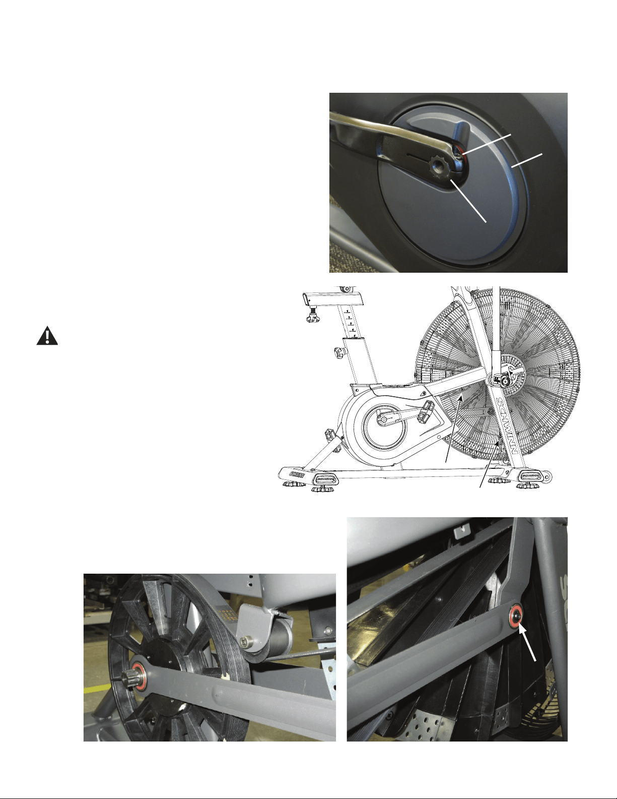
42
NOTICE: It is necessary to remove the Shrouds for this procedure. Refer to the “Replace the Shrouds” procedure.
Note: Your machine may not match the image. For reference only.
1. Using an 8mm hex key, remove the Cap Screw (A) from the Crank
Arm assembly (B).
NOTICE: Hold the Crank Arm assembly so that it does not fall.
2. Remove the Crank Arm assembly (B) from the Crank Link Assembly
shaft (C). Set it safely aside.
3. Carefully remove the Shrouds. Set them safely aside for
reassembly. Refer to the “Replace the Shrouds” procedure in the
Service Manual.
Be aware that the Pedals, Handlebars and Resistance
Fan are connected and when any of these parts move
the others do as well.
4. Using a #2 Phillips Screwdriver, loosen and remove the
screws that attach the lower Fan Cage. Carefully remove the
lower Fan Cage sections. Set them safely aside for reassembly.
5. Using a 5 mm hex key, loosen and remove the indicated screw and
washer that attach the Linkage Arm to the Arm Pivot. Carefully remove the
Linkage Arm from the Arm Pivot and the Crank Link Assembly shaft, using
aatheadscrewdrivertoprythebearingsofftheshaft.Setitsafelyaside.
AA
CC
BB
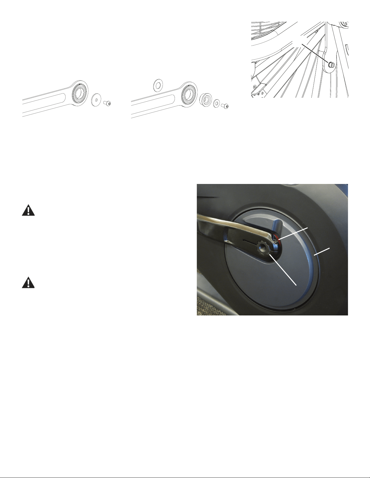
43
6. Before installing the new Linkage Arm, check the diameter of the
small pivot shaft (P) on the Arm Pivot. Use the appropriate hardware in the
Linkage Arm service kit for your machine.
6. Installation is the reverse procedure. Put the Right Shroud in position
rsttoalignthescrewsfortheLeftShroud.Installthetopscrewsrst.
NOTICE: Be sure the tabs in the Top Shroud snap into the Main
Assembly.
Completely tighten the Cap Screws (A) on the Crank Arms or torque to 60
N.m.
The Left Crank Arm has an “L”, the Right Crank Arm an “R.
Orientation is based from a seated position on the bike. Make
sure the Crank Arms are secure before you exercise.
7. Final Inspection
Inspect your machine to ensure that all hardware is tight and components
are properly assembled.
Do not use until the machine has been fully assembled and
inspected for correct performance in accordance with the
Owner’s Manual.
AA
CC
BB
(60 N.m)
P
12mm dia. pivot shaft
25mm dia. pivot shaft
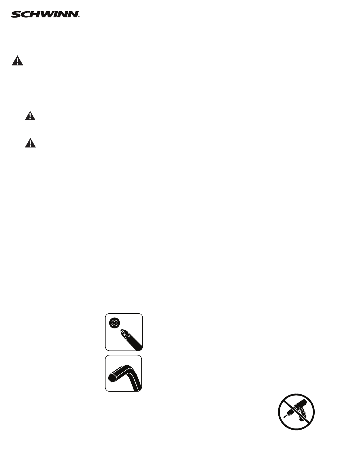
44
Replace the RPM Sensor (Speed Sensor) on the
Schwinn® AD7 AirDyne® Bike Skill Level: II
8014202.021522.C
Replacement Procedure
NOTICE: This document provides instructions for the replacement of the RPM Sensor (Speed Sensor) on the Schwinn® AD7 AirDyne® Bike.
If you need assistance, please call Schwinn Customer Service (if purchased in US/Canada) or your local distributor (if purchased out-
side US/Canada). To nd your local distributor, go to: www.nautilusinternational.com
This icon means a potentially hazardous situation which, if not avoided, could result in death or serious injury. Read and understand
all Warnings on this machine.
Tools Required (not included)
#2 Phillips screwdriver 3’ (91 cm) length of string
#0 Phillips screwdriver
6mm hex key
Important Safety Instructions
This icon means a potentially hazardous situation which, if not avoided, could result in death or serious injury. Read and
understand all Warnings on this machine.
Before servicing or using this equipment, obey the following warnings:
Read and understand the Service Manual before working on the machine. Failure to obey the instructions and safety warnings
could cause injury to the service technician or bystanders.
• Keep bystanders and children away from the product being serviced at all times.
• Makesurethattherepairisdoneinanappropriateworkspaceawayfromfoottrafcandexposuretobystanders.
• Disconnect all power to the machine before you service it.
• Some components of the equipment can be heavy or awkward. Enlist the service of a second person when you do maintenance steps involving
these components. Do not try to do heavy or awkward steps on your own.
• If replacement parts are necessary, use only genuine replacement parts and hardware supplied by Nautilus. Failure to use genuine replacement
parts can cause a risk to users, keep the machine from operating correctly and void the warranty.
• Be sure that all warning stickers and instructional placards applied to the product stay present and in good condition when doing maintenance or
replacing components. If at any time the Warning labels become loose, unreadable or dislodged, replace the labels. If purchased in US/Canada,
contact Customer Service for replacement labels. If purchased outside US/Canada, contact your local distributor for them..
• Do not try to change the design or functionality of the machine being serviced as this can adversely affect user safety.
• Donotputthemachinebackinserviceuntilallshrouds,instructions,warninglabelsandcorrectfunctionalityhavebeenveriedandtestedfor
correct performance.
• SAVE THESE INSTRUCTIONS.
Nautilus, Inc., www.NautilusInc.com, 5415 Centerpoint Parkway, Groveport, OH 43125 U.S.A. - Customer Service: North America (800) 605-3369, [email protected] | outside U.S. www.nautilusinternational.com | © 2016
Nautilus, Inc. | Schwinn, the Schwinn Quality logo, and AirDyne are trademarks owned by or licensed to Nautilus, Inc., which are registered or otherwise protected by common law in the United States and other countries.
Polar® is a registered trademarks of its owner. | ORIGINAL DOCUMENT - ENGLISH VERSION ONLY
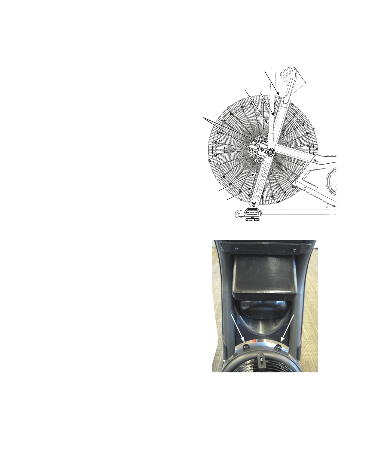
45
Note: Your machine may not match the image. For reference only.
1. Unplug the AC Adapter from the wall outlet and machine.
2. Using a #2 Phillips Screwdriver, loosen and remove the screws (*)
that attach the left Fan Adjustment Plate Cover. Carefully remove the Fan
Adjustment Plate Cover. Set the screws and cover safely aside for reas-
sembly.
3. Loosen and remove the indicated screws that attach the Front
Fan Cage to the frame, and carefully remove the sections. Remove the
bottomscrewsrstandthenthetopscrews.Setthemsafelyasidefor
reassembly.
NOTICE: Hold each section of the Fan Cage as you loosen the
screws so that it does not fall.
4. Using a 6 mm hex key, loosen and remove the hardware that
attaches Console/Mast Assembly to the frame. Set the hardware safely
aside for reassembly.
NOTICE: Hold the Console/Mast Assembly so that it does not fall.
This step may require two people.
*
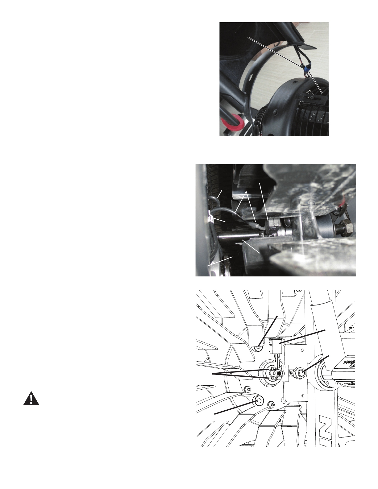
46
5. Carefully lift the Console/Mast Assembly. Disconnect the RPM Data
Cable (B) and Power Inlet Cable (C). Set the Console/Mast Assembly
safely aside for reassembly.
NOTICE: Do not let the cables fall down inside the frame. This step
may require two people.
6. Observe the cable routing to the RPM Sensor (A). Tie the piece of
string to the end of the RPM Data Cable (B) at the top opening in the
frame.
7. Carefully open the cable clip (D) that secures the RPM Data Cable (B)
and Power Inlet cable (C) on the frame upright (E), and release the RPM
Data Cable.
8. Using a #0 Phillips screwdriver, remove the screws (A1) that attach
the RPM Sensor (A) to the Fan shaft (F). Carefully remove the old RPM
Sensor assembly and pull the cable (B) so that the string extends through
the frame upright.
NOTICE: Do not crimp any cables.Do not let the Power Inlet cable
(C) fall down inside the frame. This step may require two
people.
9. Untie the string from the old RPM Data cable and discard the old
RPM Sensor.
10. Installation is the reverse procedure. Tie the string to the cable end
(B) on the replacement RPM Sensor (A). Carefully pull the cable up
through the frame upright. To keep the RPM Data Cable clear of the Fan,
carefully secure RPM Data Cable in the cable clip (D) with the Power Inlet
cable (C) on the frame upright.
NOTICE: Do not crimp any cables. Make sure the RPM Sensor is
oriented correctly on the Fan Spindle. Be sure the routing
for the cables is correct to prevent interference from
moving parts.
Note: Before fully attaching the Fan Cage, verify that the RPM
Sensor (A) and Speed Sensor Magnets (G) on the Fan
Assembly do not touch.
11. Final Inspection
Inspect your machine to ensure that all hardware is tight and components
are properly assembled.
Do not use until the machine has been fully assembled and
inspected for correct performance in accordance with the
Owner’s Manual.
B
C
RPM Sensor cable – frame to sensor (top back view)
B
A
C
D
E F
A
A1
F
G
G
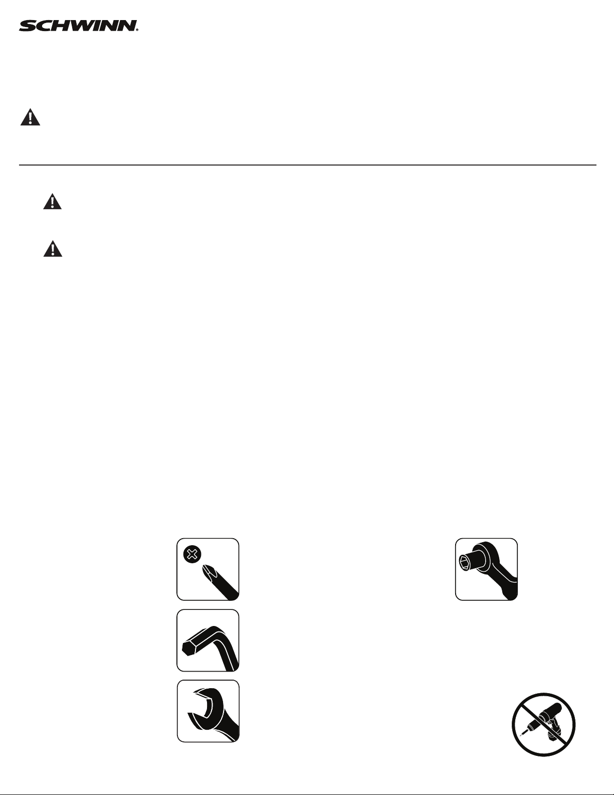
47
Replace the Drive Belt and Fan Assembly
on the Schwinn® AD7 AirDyne® Bike Skill Level: II
8014203.021522.C
Replacement Procedure
NOTICE: This document provides instructions for the replacement of the Drive Belt and Fan Assembly on the Schwinn® AD7 AirDyne® Bike.
If you need assistance, please call Schwinn Customer Service (if purchased in US/Canada) or your local distributor (if purchased out-
side US/Canada). To nd your local distributor, go to: www.nautilusinternational.com
This icon means a potentially hazardous situation which, if not avoided, could result in death or serious injury. Read and understand
all Warnings on this machine.
Tools Required (not included)
#2 Phillips screwdriver 19mm socket and wrench
#0 Phillips screwdriver
6mm hex key 6mm calibrated torque wrench (40 N.m)
5mm hex key
28mm spacer (or old Drive Belt)
10mm open end wrench
19mm open end wrench
Important Safety Instructions
This icon means a potentially hazardous situation which, if not avoided, could result in death or serious injury. Read and
understand all Warnings on this machine.
Before servicing or using this equipment, obey the following warnings:
Read and understand the Service Manual before working on the machine. Failure to obey the instructions and safety warnings
could cause injury to the service technician or bystanders.
• Keep bystanders and children away from the product being serviced at all times.
• Makesurethattherepairisdoneinanappropriateworkspaceawayfromfoottrafcandexposuretobystanders.
• Disconnect all power to the machine before you service it.
• Some components of the equipment can be heavy or awkward. Enlist the service of a second person when you do maintenance steps involving
these components. Do not try to do heavy or awkward steps on your own.
• If replacement parts are necessary, use only genuine replacement parts and hardware supplied by Nautilus. Failure to use genuine replacement
parts can cause a risk to users, keep the machine from operating correctly and void the warranty.
• Be sure that all warning stickers and instructional placards applied to the product stay present and in good condition when doing maintenance or
replacing components. If at any time the Warning labels become loose, unreadable or dislodged, replace the labels. If purchased in US/Canada,
contact Customer Service for replacement labels. If purchased outside US/Canada, contact your local distributor for them..
• Do not try to change the design or functionality of the machine being serviced as this can adversely affect user safety.
• Donotputthemachinebackinserviceuntilallshrouds,instructions,warninglabelsandcorrectfunctionalityhavebeenveriedandtestedfor
correct performance.
• SAVE THESE INSTRUCTIONS.
Nautilus, Inc., www.NautilusInc.com, 5415 Centerpoint Parkway, Groveport, OH 43125 U.S.A. - Customer Service: North America (800) 605-3369, [email protected] | outside U.S. www.nautilusinternational.com | © 2016
Nautilus, Inc. | Schwinn, the Schwinn Quality logo, and AirDyne are trademarks owned by or licensed to Nautilus, Inc., which are registered or otherwise protected by common law in the United States and other countries.
Polar® is a registered trademarks of its owner. | ORIGINAL DOCUMENT - ENGLISH VERSION ONLY
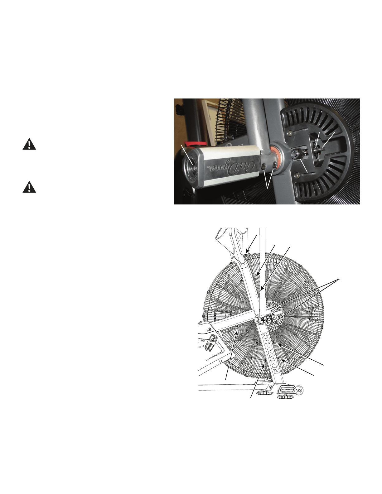
48
NOTICE: It is necessary to remove the Shrouds for this procedure. Refer to the “Replace the Shrouds” procedure.
It is necessary to adjust the Drive Belt tension at the end of this procedure. Refer to the “Belt Tension Adjustment” procedure.
Note: Your machine may not match the image. For reference only.
1. Unplug the AC Adapter from the wall outlet and machine.
2. Loosen the hardware (A) that attaches the Right Foot Peg
to the frame assembly. Remove the hardware and Foot Peg, and
set them safely aside. Loosen and remove the screws (B) that
attach the Right Handlebar Arm to the Arm Pivot assembly. Set
them safely aside.
Be aware that the Pedals, Handlebars and Resistance
Fan are connected and when any of these parts move
the others do as well.
3. Remove the Right Handlebar Arm and set it safely aside.
Do not use a hammer to remove the handlebar.
4. Carefully remove the Top and Right Shrouds. Refer to the “Replace
the Shrouds” procedure in this manual.
5. Loosen and remove the indicated screws that attach the Fan
Adjustment Plate Covers (*) and Front and Lower Fan Cage to the frame.
Carefully remove the Fan Cage sections and Fan Adjustment Plate
Covers. Set them safely aside for reassembly.
NOTICE: Hold each section of the Fan Cage as you loosen the
screws so that it does not fall. If necessary, loosen and
remove the screws that attach the sections of the Fan Cage
to each other.
A
B
CC D
E
*
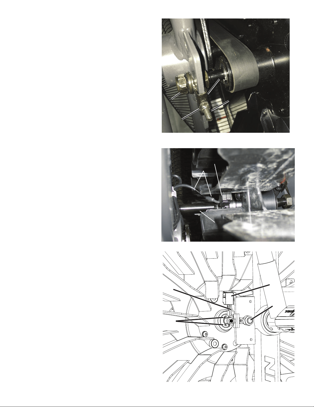
49
6. Using a 19mm open end wrench, loosen and remove the Fan spindle
lock nuts (E) on both sides of the machine. Set them safely aside for
reassembly.
Note: If you are only replacing the Drive Belt, it is only necessary to
loosen these parts.
7. Using a 10mm open end wrench, loosen and remove the Adjustment
Nuts (C), Spindle Clips (F) and Threaded Tensioners (D) on both sides of
the machine. Set them safely aside for reassembly.
8. Using a #0 Phillips screwdriver, loosen and remove the screws (G1)
that attach the RPM Sensor (G) to the Fan Assembly shaft (J). Carefully
remove the RPM Sensor and put it and the RPM Data Cable (H) safely
aside.
Note: If you are only replacing the Drive Belt, it is not necessary to
do this step.
RPM Sensor cable – frame to sensor (top back view)
G
G1
J
H
H
G
J
DD
EE
CC
FF
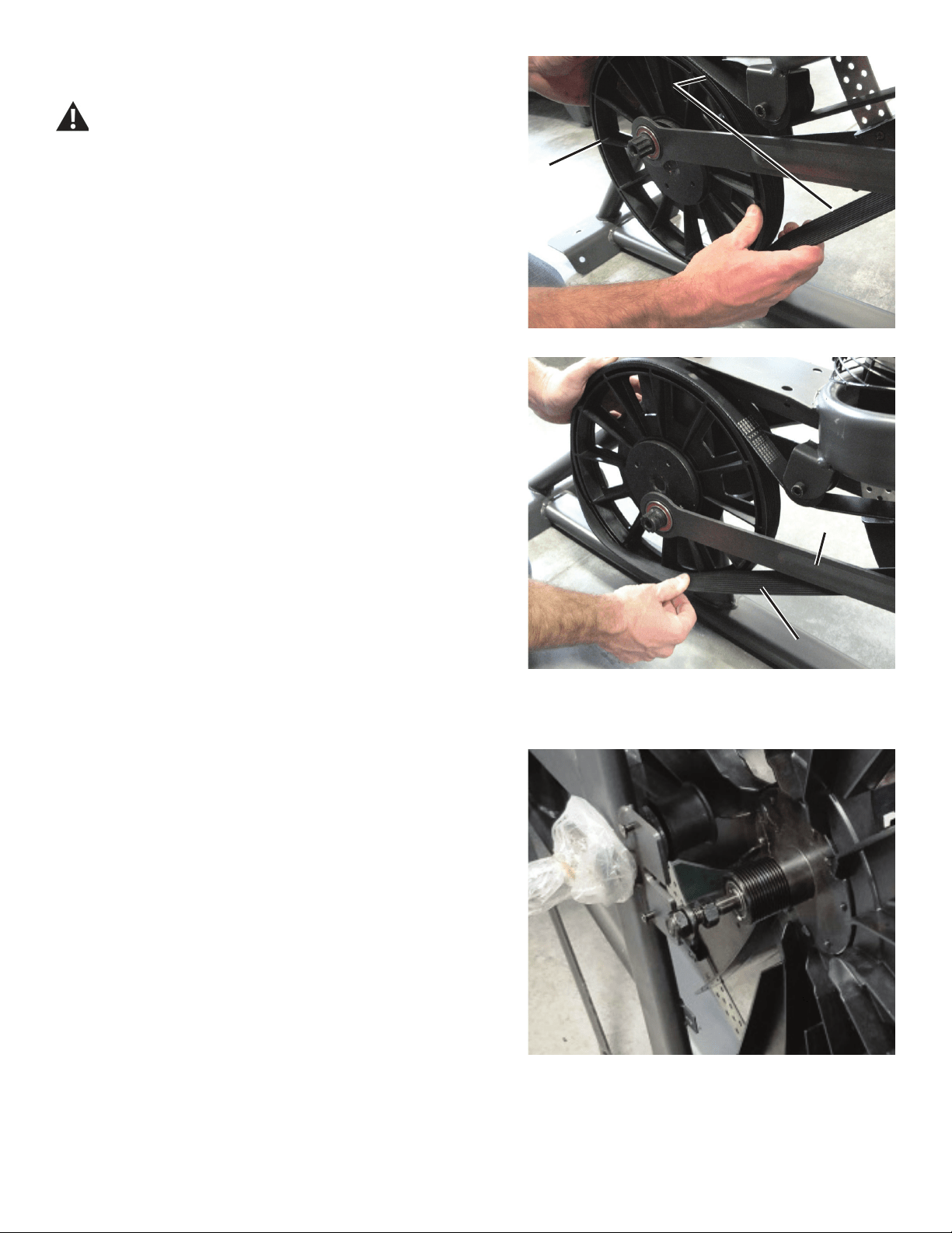
50
9. Slowly turn the Drive Pulley (L) forward and carefully ease the Drive
Belt (M) off the Drive Pulley to the outside from the bottom of the pulley.
Be sure to keep ngers clear of all pinch hazards as you turn
the Drive Pulley.
10. Carefully remove the Fan Assembly from the frame brackets and the
Drive Belt (M).
NOTICE: This step may require two people.
L
MM
N
MM
Crank arm not shown
Fan shaft removed from frame bracket and Drive Belt
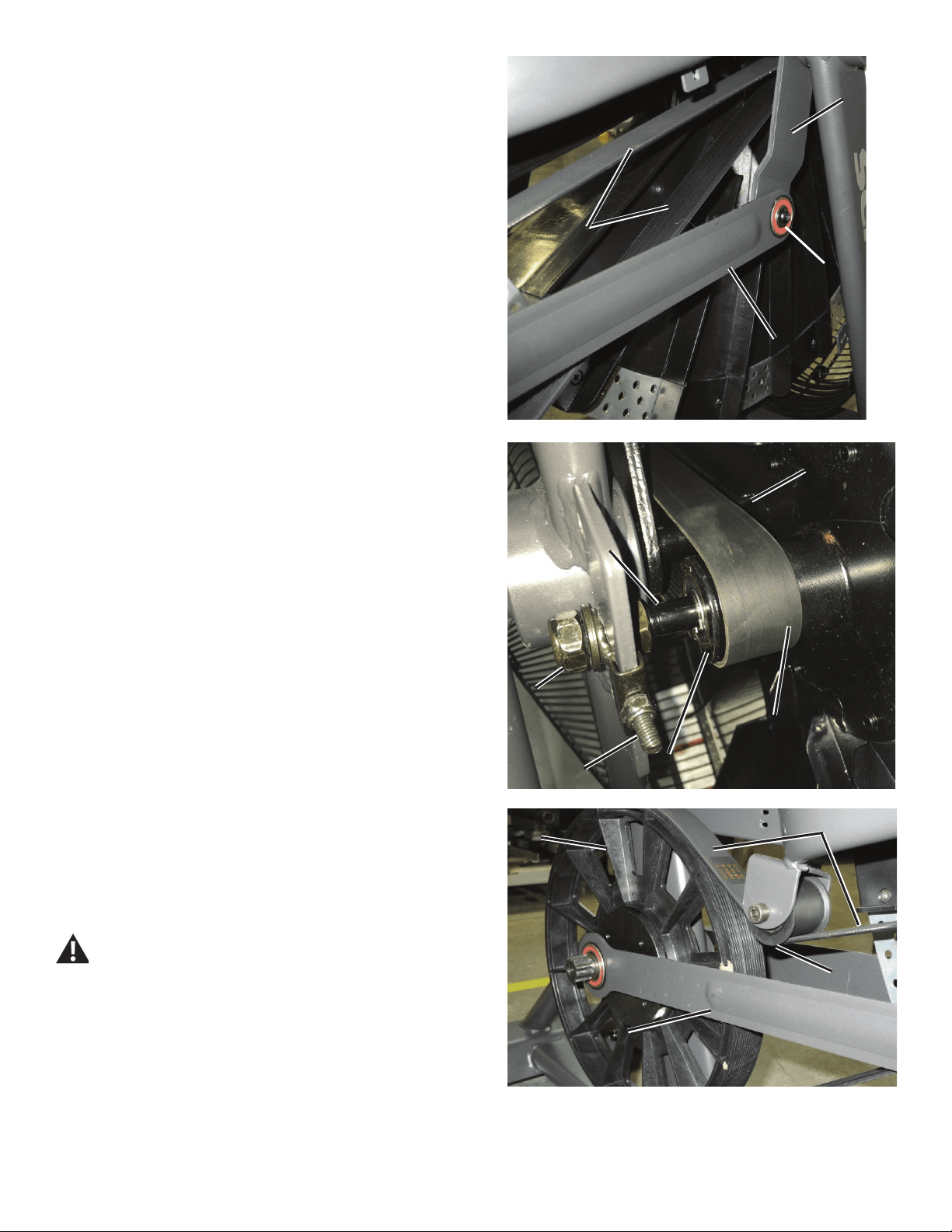
51
OO
NN
N1N1
MM
11. To remove the Drive Belt (M), loosen and remove the hardware (N1)
that attaches the right Linkage Arm (N) to the Arm Pivot (O), using the 5
mm hex key. Set the screws safely aside for reassembly. Separate the
Linkage Arm from the Arm Pivot. Remove the old Drive Belt and set it
safely aside.
12. Hold the Fan Assembly near the frame brackets and put the new
Drive Belt (M) in position on the Fan pulley (P). Be sure that the upper
portion of the Drive Belt is above the spindle (Q).
NOTICE: This step may require two people.
13. Align the Fan shaft (J) in the frame brackets. Put the Threaded
Tensioners (D) on both ends of the Fan shaft. Hand tighten the Fan
spindle lock nuts (E) on each end of the Fan shaft.
14. To put the Drive Belt (M) onto the Drive Pulley (L), align the grooves
of the belt with the grooves at the top of the pulley, with the slack of the
belt to the outside. While holding the belt on the pulley, rotate the Drive
Pulley backward until the belt is completely seated in the grooves. Make
sure the Drive Belt is aligned on the Fan pulley (P), Idler Pulley (Q), Rear
Idler Pulley (R) and Drive Pulley.
Be sure to keep ngers clear of all pinch hazards as you turn
the Drive Pulley.
15. Reattach the right Linkage Arm (N) to the Arm Pivot (O).
LL
MM
NN
RR
MM
QQ
EE
JJ
PP
DD
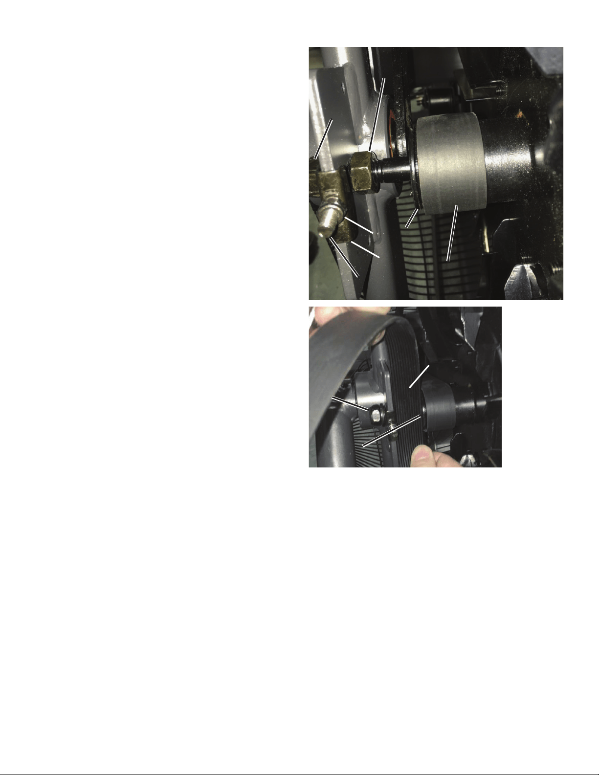
52
16. Move the Fan spindle backward in the frame brackets to the end of
the slots. Reinstall the Adjustment Nuts (C) and Spindle Clips (F) on the
Threaded Tensioners (D) on both sides of the machine so the the Spindle
Clips just touch the frame brackets and the Adjustment Nuts just touch the
Spindle Clips. Tighten the Adjustment Nuts 9 turns.
Note: This step may require two people. If using a tension
measuring tool, adjust the Drive Belt to 891 N +/- 67 N.
17. Make sure the Drive Belt (M) is centered on the Fan hub (P) and the
Drive Pulley (L). The Fan hub should have 1 groove visible to the left of
the belt, and not extend over the right side of the hub.
18. Check the side-to-side position of the Fan. With the Fan spindle lock
nuts (E) loosened, adjust the Fan spindle jam nuts (K) to allow a gap of
28mm between the outer face of the Fan hub (P) and the frame bracket
steel plate. (28mm = width of old Drive Belt.)
19. Using the 19 mm open end wrench, tighten the Fan spindle lock
nuts (E) on each end of the Fan shaft (J). If a torque wrench is available,
tighten nuts to 10 N.m.
Note: If necessary, hold the Fan spindle jam nuts (K) so that they do
not spin.
Right side – Fan hub alignment (front top view)
CC
KK
FF
PP
EE
MM
DD
28mm28mm
EE
PP
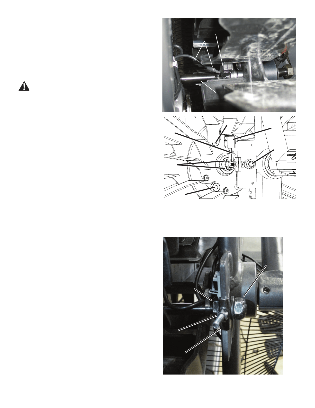
53
Left side – Fan tension adjustment (top front view)
G
G1
J
H
S
S
20. Reinstall the RPM Sensor (G) to the Fan shaft (J). Keep the RPM
Data cable (H) clear of the Fan.
NOTICE: Do not crimp any cables. Make sure the RPM Sensor is
oriented correctly on the Fan Spindle. Be sure the routing
for the cables is correct to prevent interference from
moving parts.
Note: Before fully attaching the Fan Cage, verify that the RPM
Sensor (G) and Speed Sensor Magnets (S) on the Fan
Assembly do not touch.
Be aware that the Pedals, Handlebars and Resistance Fan are
connected and when any of these parts move the others do as
well.
21. Reinstall Fan Cage and test ride the machine to as high a speed as
possible.
If the machine operates with no popping noises—go to Step 25.
If the Drive Belt or Fan makes noises—continue to Step 22.
22. Tighten the left Tension Adjustment Nut (C, on the side of the Fan
without the Drive Belt) 1/2 turn at a time, and test for quiet operation.
Repeat until the noise is gone. If the nut is adjusted more than 2 1/2 turns,
the Fan Pulley (P) position may need adjustment. This is necessary if the
Fan starts to make additional noise.
If the machine operates with no popping noises—go to Step 25.
If the Drive Belt or Fan makes additional noises—continue to Step 23.
23. Remove the Front Fan Cage (see Step 4). Loosen the Tension
Adjustment Nuts (C) until the Spindle Clips (F) are loose. Loosen the right
Fan spindle jam nut (K). Tighten the left Fan spindle jam nut 1 full turn
(toward the Frame mount bracket). Retighten the right Fan spindle jam nut
to the mount bracket.
Repeat Steps 18-21.
24. Reinstall the Fan Cage.
25. Using the 19 mm open end wrench, tighten the Fan spindle lock
nuts (E) on each end of the Fan shaft (J). If a torque wrench is available,
tighten nuts to 10 N.m.
H
G
J
EE
CC
FF
KK
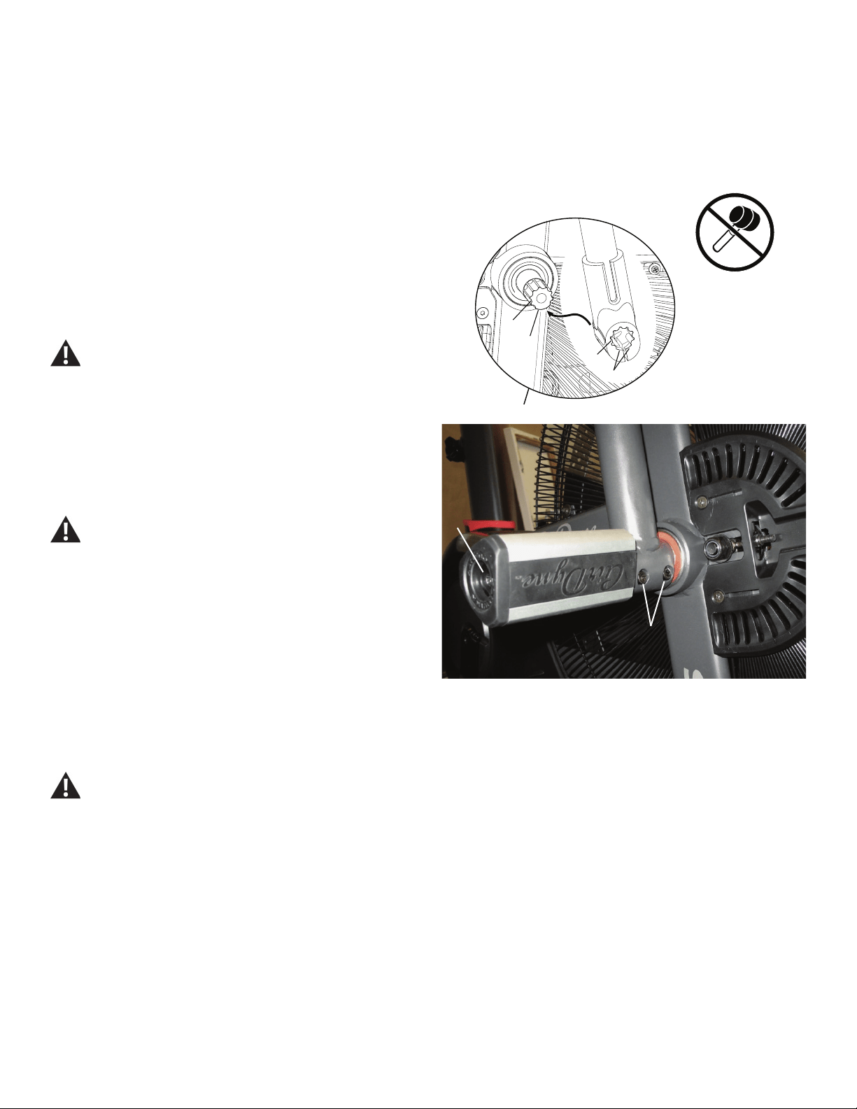
54
A
B
(40 N.m)
26. Reinstall the Fan Adjustment Plate Covers.
27. Reinstall the Shrouds. Refer to the “Replace the Shrouds” procedure
in this manual.
NOTICE: Be sure the tabs in the Top Shroud snap into the Main
Assembly.
28. Reinstall the Right Handlebar Arm and Right Foot Peg.
NOTICE: Align the open curve (a) on the handlebar with the smooth
curve (1a) on the pivot shaft and make sure the indents (b)
are exactly aligned. Carefully push the handlebar onto the
shaft. Do not force or hammer into position. Gently rock
the handlebar forward and backward to make sure it is fully
seated on the shaft.
Fully tighten the Cap Screws (B) on the Handlebar Arm or
torque to 40 N.m.
NOTICE: Push the Shoulder Bolt (A) completely through the Foot
Peg, and press the plastic washer tightly onto the end of
the Foot Peg. Be sure the washer does not touch the bolt
threads. Do not let the washer fall off the Foot Peg during
installation.
Fully tighten hardware. Make sure the Handlebar Arms are
secure before you exercise.
29. Final Inspection
Inspect your machine to ensure that all hardware is tight and components
are properly assembled.
Do not use until the machine has been fully assembled and
inspected for correct performance in accordance with the
Owner’s Manual.
1a
b
a
b
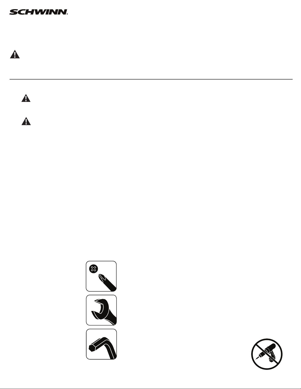
55
Replace the Rear Idler Pulley
on the Schwinn® AD7 AirDyne® Bike Skill Level: II
8014204.021522.C
Replacement Procedure
NOTICE: This document provides instructions for the replacement of the Belt Tensioner Assembly (Idler Assembly) on the Schwinn® AD7 AirDyne® Bike.
If you need assistance, please call Schwinn Customer Service (if purchased in US/Canada) or your local distributor (if purchased out-
side US/Canada). To nd your local distributor, go to: www.nautilusinternational.com
This icon means a potentially hazardous situation which, if not avoided, could result in death or serious injury. Read and understand
all Warnings on this machine.
Tools Required (not included)
#2 Phillips screwdriver
10mm open end wrench
19mm open end wrench
13mm open end wrench
6mm hex key
Important Safety Instructions
This icon means a potentially hazardous situation which, if not avoided, could result in death or serious injury. Read and
understand all Warnings on this machine.
Before servicing or using this equipment, obey the following warnings:
Read and understand the Service Manual before working on the machine. Failure to obey the instructions and safety warnings
could cause injury to the service technician or bystanders.
• Keep bystanders and children away from the product being serviced at all times.
• Makesurethattherepairisdoneinanappropriateworkspaceawayfromfoottrafcandexposuretobystanders.
• Disconnect all power to the machine before you service it.
• Some components of the equipment can be heavy or awkward. Enlist the service of a second person when you do maintenance steps involving
these components. Do not try to do heavy or awkward steps on your own.
• If replacement parts are necessary, use only genuine replacement parts and hardware supplied by Nautilus. Failure to use genuine replacement
parts can cause a risk to users, keep the machine from operating correctly and void the warranty.
• Be sure that all warning stickers and instructional placards applied to the product stay present and in good condition when doing maintenance or
replacing components. If at any time the Warning labels become loose, unreadable or dislodged, replace the labels. If purchased in US/Canada,
contact Customer Service for replacement labels. If purchased outside US/Canada, contact your local distributor for them..
• Do not try to change the design or functionality of the machine being serviced as this can adversely affect user safety.
• Donotputthemachinebackinserviceuntilallshrouds,instructions,warninglabelsandcorrectfunctionalityhavebeenveriedandtestedfor
correct performance.
• SAVE THESE INSTRUCTIONS.
Nautilus, Inc., www.NautilusInc.com, 5415 Centerpoint Parkway, Groveport, OH 43125 U.S.A. - Customer Service: North America (800) 605-3369, [email protected] | outside U.S. www.nautilusinternational.com | © 2016
Nautilus, Inc. | Schwinn, the Schwinn Quality logo, and AirDyne are trademarks owned by or licensed to Nautilus, Inc., which are registered or otherwise protected by common law in the United States and other countries.
Polar® is a registered trademarks of its owner. | ORIGINAL DOCUMENT - ENGLISH VERSION ONLY
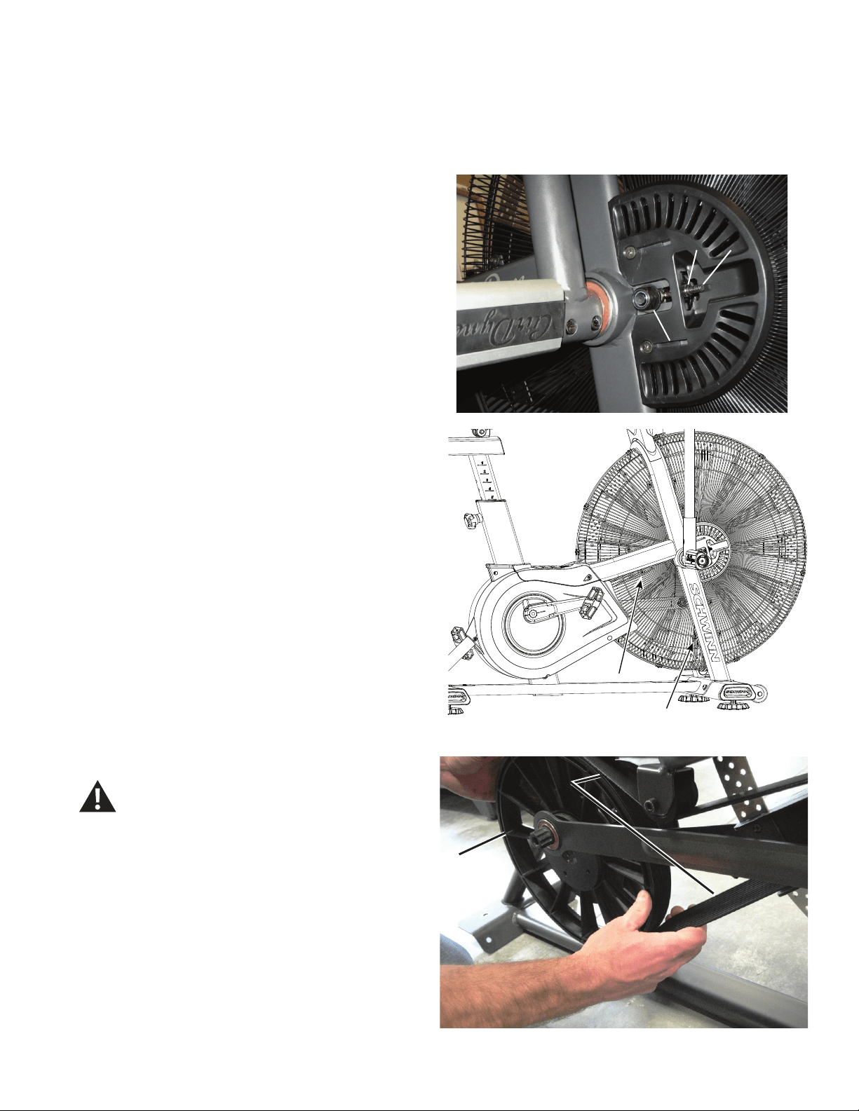
56
NOTICE: It is necessary to remove the Shrouds for this procedure. Refer to the “Replace the Shrouds” procedure.
It is necessary to adjust the Drive Belt tension at the end of this procedure. Refer to the “Belt Tension Adjustment” procedure
Note: Your machine may not match the image. For reference only.
1. Unplug the AC Adapter from the wall outlet and machine.
2. Record the position of the Tension Adjustment Nuts (A) on the
Threaded Tensioners (B) on both sides of the machine. Count the threads
or mark a piece of paper.
3. Carefully remove the Shrouds. Refer to the “Replace the Shrouds”
procedure in this manual.
4. Using a #2 Phillips Screwdriver, loosen and remove the screws
that attach the lower Fan Cage. Carefully remove the lower Fan Cage
sections. Set them safely aside for reassembly.
5. Using a 19mm open end wrench, loosen the Fan spindle lock nuts
(C) on the Threaded Tensioner (B) on both sides of the machine.
6. Using a 10mm open end wrench, loosen the Adjustment Nuts (A) on
both sides of the machine.
7. Slowly turn the Drive Pulley (D) forward and carefully ease the Drive
Belt (E) off the Drive Pulley to the outside from the bottom of the pulley.
Be sure to keep ngers clear of all pinch hazards as
you turn the Drive Pulley.
AA B
C
D
EE
Crank arm not shown
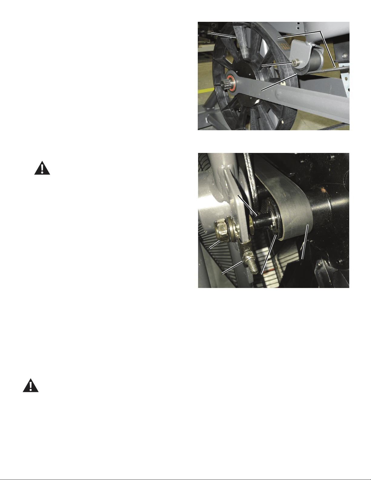
57
DD
EE
FF
GG
Front end belt alignment (Fan cage not shown for clarity)
8. Using 13 mm wrench and 6mm hex key, loosen and remove the
hardware (F) from the Rear Idler Pulley assembly (G). Remove the Rear
Idler Pulley from the bracket and Drive Belt (E). Discard the old Rear Idler
Pulley assembly.
9. Install the new Rear Idler Pulley (G).
NOTICE: Do not overtighten the hardware (F). The Rear Idler Pulley
must be able to turn. If the hardware is too tight, this can
cause wear on the bearings.
10. To put the Drive Belt (E) onto the Drive Pulley (D), align the grooves
of the belt with the grooves at the top of the pulley, with the slack of the
belt to the outside. While holding the belt on the pulley, rotate the Drive
Pulley backward until the belt is completely seated on the pulley. Make
sure the Drive Belt is aligned on the Fan pulley (H), Rear Idler Pulley (G)
and Drive Pulley.
Be sure to keep ngers clear of all pinch hazards as
you turn the Drive Pulley.
11. Using a 10mm open end wrench, adjust the Tension Adjustment Nuts
(A) to the position recorded in step 2, on both sides of the machine.
12. Using the 19 mm open end wrench, tighten the Fan spindle lock nuts
(C) on each end of the Fan shaft (K).
13. Reinstall the Shrouds. Refer to the “Replace the Shrouds” procedure
in this manual.
NOTICE: Be sure the tabs in the Top Shroud snap into the Main
Assembly.
14. Make sure that the belt tension is correct. Refer to the “Belt Tension
Adjustment” section in this manual.
Note: This step may require two people.
15. Final Inspection
Inspect your machine to ensure that all hardware is tight and components
are properly assembled.
Do not use until the machine has been fully assembled and
inspected for correct performance in accordance with the
Owner’s Manual.
EE
CC
KK
HH
AA

58
Replace the Crank Link Assembly
on the Schwinn® AD7 AirDyne® Bike Skill Level: II
8014205.021522.C
Replacement Procedure
NOTICE: This document provides instructions for the replacement of the Crank Link Assembly on the Schwinn® AD7 AirDyne® Bike.
If you need assistance, please call Schwinn Customer Service (if purchased in US/Canada) or your local distributor (if purchased out-
side US/Canada). To nd your local distributor, go to: www.nautilusinternational.com
This icon means a potentially hazardous situation which, if not avoided, could result in death or serious injury. Read and understand
all Warnings on this machine.
Tools Required (not included)
#2 Phillips screwdriver 8mm hex key
6mm hex key
5mm hex key
Smallatheadscrewdriver 6mmcalibratedtorquewrench(40N.m)
8mm calibrated torque wrench (60 N.m)
Important Safety Instructions
This icon means a potentially hazardous situation which, if not avoided, could result in death or serious injury. Read and
understand all Warnings on this machine.
Before servicing or using this equipment, obey the following warnings:
Read and understand the Service Manual before working on the machine. Failure to obey the instructions and safety warnings
could cause injury to the service technician or bystanders.
• Keep bystanders and children away from the product being serviced at all times.
• Makesurethattherepairisdoneinanappropriateworkspaceawayfromfoottrafcandexposuretobystanders.
• Disconnect all power to the machine before you service it.
• Some components of the equipment can be heavy or awkward. Enlist the service of a second person when you do maintenance steps involving
these components. Do not try to do heavy or awkward steps on your own.
• If replacement parts are necessary, use only genuine replacement parts and hardware supplied by Nautilus. Failure to use genuine replacement
parts can cause a risk to users, keep the machine from operating correctly and void the warranty.
• Be sure that all warning stickers and instructional placards applied to the product stay present and in good condition when doing maintenance or
replacing components. If at any time the Warning labels become loose, unreadable or dislodged, replace the labels. If purchased in US/Canada,
contact Customer Service for replacement labels. If purchased outside US/Canada, contact your local distributor for them..
• Do not try to change the design or functionality of the machine being serviced as this can adversely affect user safety.
• Donotputthemachinebackinserviceuntilallshrouds,instructions,warninglabelsandcorrectfunctionalityhavebeenveriedandtestedfor
correct performance.
• SAVE THESE INSTRUCTIONS.
Nautilus, Inc., www.NautilusInc.com, 5415 Centerpoint Parkway, Groveport, OH 43125 U.S.A. - Customer Service: North America (800) 605-3369, [email protected] | outside U.S. www.nautilusinternational.com | © 2016
Nautilus, Inc. | Schwinn, the Schwinn Quality logo, and AirDyne are trademarks owned by or licensed to Nautilus, Inc., which are registered or otherwise protected by common law in the United States and other countries.
Polar® is a registered trademarks of its owner. | ORIGINAL DOCUMENT - ENGLISH VERSION ONLY
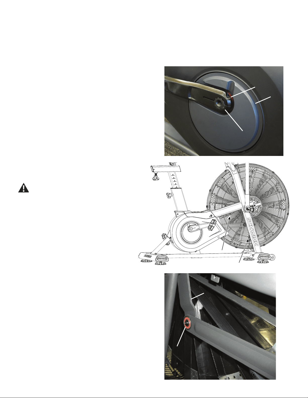
59
NOTICE: It is necessary to remove the Shrouds for this procedure. Refer to the “Replace the Shrouds” procedure.
Note: Your machine may not match the image. For reference only.
1. Unplug the AC Adapter from the wall outlet and machine.
2. Using an 8mm hex key, remove the Cap Screw (A) from the Left
Crank Arm assembly (B).
NOTICE: Hold the Crank Arm assembly so that it does not fall.
3. Remove the Left Crank Arm assembly (B) from the Crank Link
Assembly shaft (C). Set it safely aside.
4. Carefully remove the Shrouds. Set them safely aside for
reassembly. Refer to the “Replace the Shrouds” procedure in this
manual.
Be aware that the Pedals, Handlebars and Resistance
Fan are connected and when any of these parts move
the others do as well.
5. Using a #2 Phillips Screwdriver, loosen and remove the
screws that attach the lower Fan Cage. Carefully remove the
lower Fan Cage sections. Set them safely aside for reassembly.
6. Using a 5 mm hex key, loosen and remove the screw and washer (D)
that attach the left Linkage Arm to the Arm Pivot (E). Carefully remove the
Linkage Arm from the Arm Pivot and the Crank Link Assembly (F), using a
atheadscrewdrivertoprythebearingsofftheshaft.Setitsafelyaside.
AA
CC
BB
DD
EE
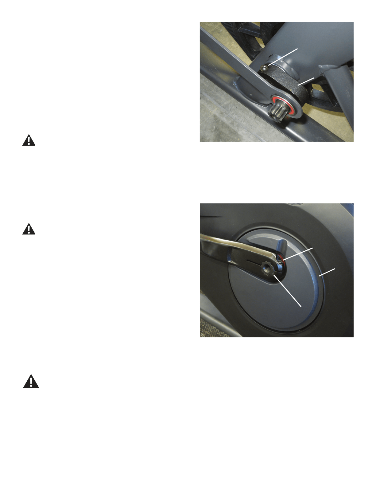
60
7. Using a 6 mm hex key, loosen and remove the Cap Screw (G) that
secures the Crank Link Assembly (F) to the Pulley spindle. Remove the
old Crank Link Assembly and discard.
8. Installation is the reverse procedure.
Put the replacement Crank Link Assembly (F) in position on the Pulley
spindle and completely tighten the Cap Screw (G), or torque to 40 N.m.
Make sure the Crank Link Assembly is secure on the Pulley
spindle before you reinstall the Linkage Arm.
PuttheRightShroudinpositionrsttoalignthescrewsfortheLeft
Shroud.Installthetopscrewsrst.
NOTICE: Be sure the tabs in the Top Shroud snap into the Main
Assembly.
Completely tighten the Cap Screw (A) on the Crank Arm (B) or torque to
60 N.m.
The Left Crank Arm has an “L”, the Right Crank Arm an “R.
Orientation is based from a seated position on the bike. Make
sure the Crank Arms are secure before you exercise.
9. Final Inspection
Inspect your machine to ensure that all hardware is tight and components
are properly assembled.
Do not use until the machine has been fully assembled and
inspected for correct performance in accordance with the
Owner’s Manual.
AA
CC
BB
(60 N.m)
GG
(40 N.m)
FF
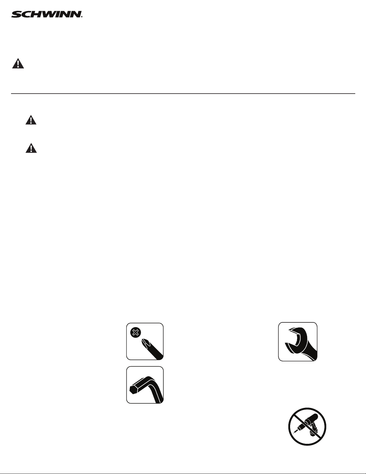
61
Replace the Power Inlet on the
Schwinn® AD7 AirDyne® Bike Skill Level: II
8014206.021522.C
Replacement Procedure
NOTICE: This document provides instructions for the replacement of the Power Inlet Assembly on the Schwinn® AD7 AirDyne® Bike.
If you need assistance, please call Schwinn Customer Service (if purchased in US/Canada) or your local distributor (if purchased out-
side US/Canada). To nd your local distributor, go to: www.nautilusinternational.com
This icon means a potentially hazardous situation which, if not avoided, could result in death or serious injury. Read and understand
all Warnings on this machine.
Tools Required (not included)
#2 Phillips screwdriver 17mm open end wrench
or adjustable wrench
6mm hex key 4’ (122 cm) length of string
Important Safety Instructions
This icon means a potentially hazardous situation which, if not avoided, could result in death or serious injury. Read and
understand all Warnings on this machine.
Before servicing or using this equipment, obey the following warnings:
Read and understand the Service Manual before working on the machine. Failure to obey the instructions and safety warnings
could cause injury to the service technician or bystanders.
• Keep bystanders and children away from the product being serviced at all times.
• Makesurethattherepairisdoneinanappropriateworkspaceawayfromfoottrafcandexposuretobystanders.
• Disconnect all power to the machine before you service it.
• Some components of the equipment can be heavy or awkward. Enlist the service of a second person when you do maintenance steps involving
these components. Do not try to do heavy or awkward steps on your own.
• If replacement parts are necessary, use only genuine replacement parts and hardware supplied by Nautilus. Failure to use genuine replacement
parts can cause a risk to users, keep the machine from operating correctly and void the warranty.
• Be sure that all warning stickers and instructional placards applied to the product stay present and in good condition when doing maintenance or
replacing components. If at any time the Warning labels become loose, unreadable or dislodged, replace the labels. If purchased in US/Canada,
contact Customer Service for replacement labels. If purchased outside US/Canada, contact your local distributor for them..
• Do not try to change the design or functionality of the machine being serviced as this can adversely affect user safety.
• Donotputthemachinebackinserviceuntilallshrouds,instructions,warninglabelsandcorrectfunctionalityhavebeenveriedandtestedfor
correct performance.
• SAVE THESE INSTRUCTIONS.
Nautilus, Inc., www.NautilusInc.com, 5415 Centerpoint Parkway, Groveport, OH 43125 U.S.A. - Customer Service: North America (800) 605-3369, [email protected] | outside U.S. www.nautilusinternational.com | © 2016
Nautilus, Inc. | Schwinn, the Schwinn Quality logo, and AirDyne are trademarks owned by or licensed to Nautilus, Inc., which are registered or otherwise protected by common law in the United States and other countries.
Polar® is a registered trademarks of its owner. | ORIGINAL DOCUMENT - ENGLISH VERSION ONLY
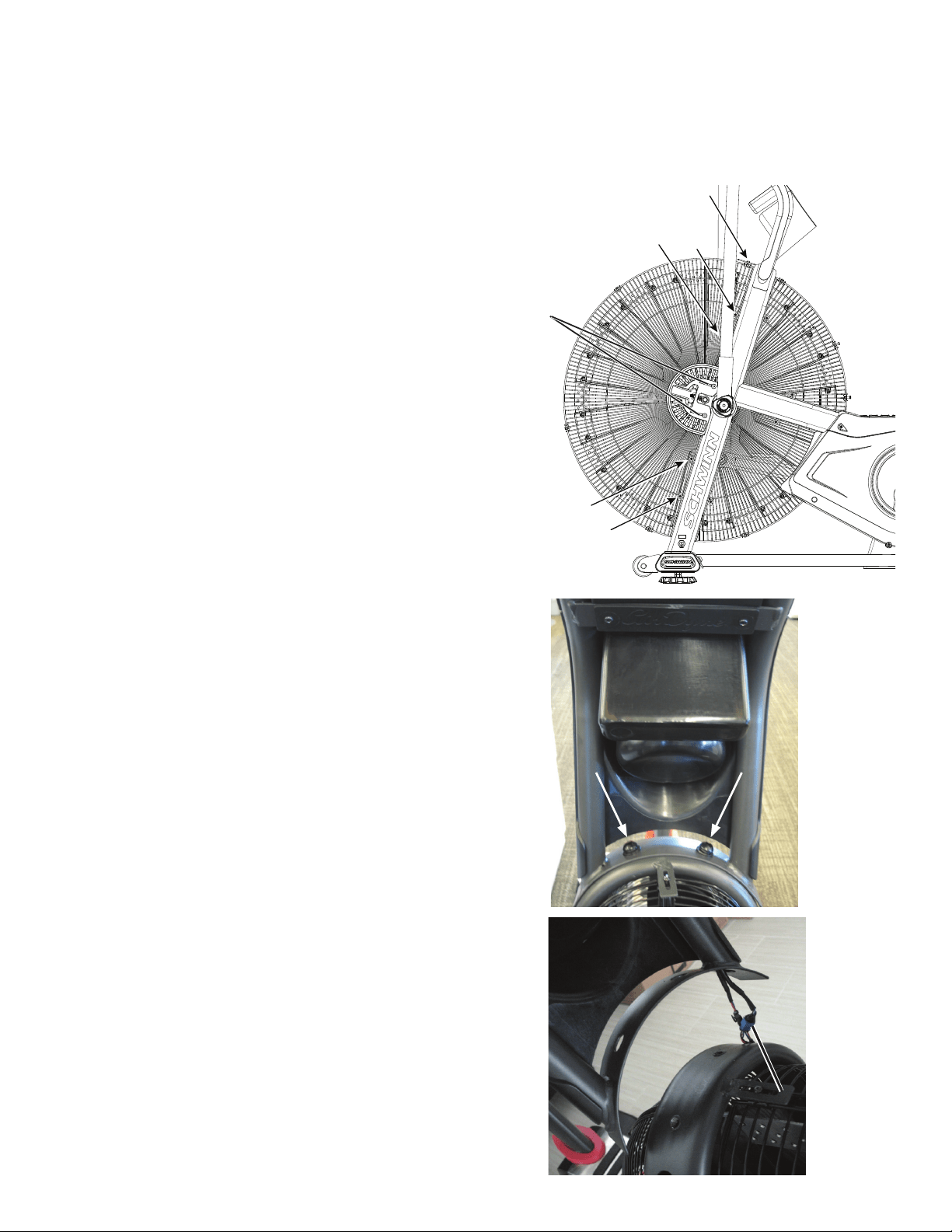
62
NOTICE: It is necessary to remove the Shrouds for this procedure. Refer to the “Replace the Shrouds” procedure.
Note: Your machine may not match the image. For reference only.
1. Unplug the AC Adapter from the wall outlet and machine.
2. Loosen and remove the screws (*) that attach the left Fan Adjustment
Plate Cover. Carefully remove the Fan Adjustment Plate Cover. Set the
screws and cover safely aside for reassembly.
3. Loosen and remove the indicated screws that attach the Front Fan
Cage sections to the Frame, and carefully remove the sections. Remove
thebottomscrewsrstandthenthetopscrews.Setthemsafelyasidefor
reassembly.
NOTICE: Hold the sections of the Fan Cage as you loosen the screws
so that they do not fall.
4. Loosen and remove the hardware that attaches the Console/Mast
Assembly to the Frame. Set the hardware safely aside for reassembly.
NOTICE: Hold the Console/Mast Assembly so that it does not fall.
This step may require two people.
5. Carefully lift the Console/Mast Assembly and disconnect the cables.
NOTICE: Do not let the cables fall down inside the Frame. This step
may require two people.
6. Tie the length of string to the end of the Power Inlet cable (A) at the
top of the Frame Upright.
*
A
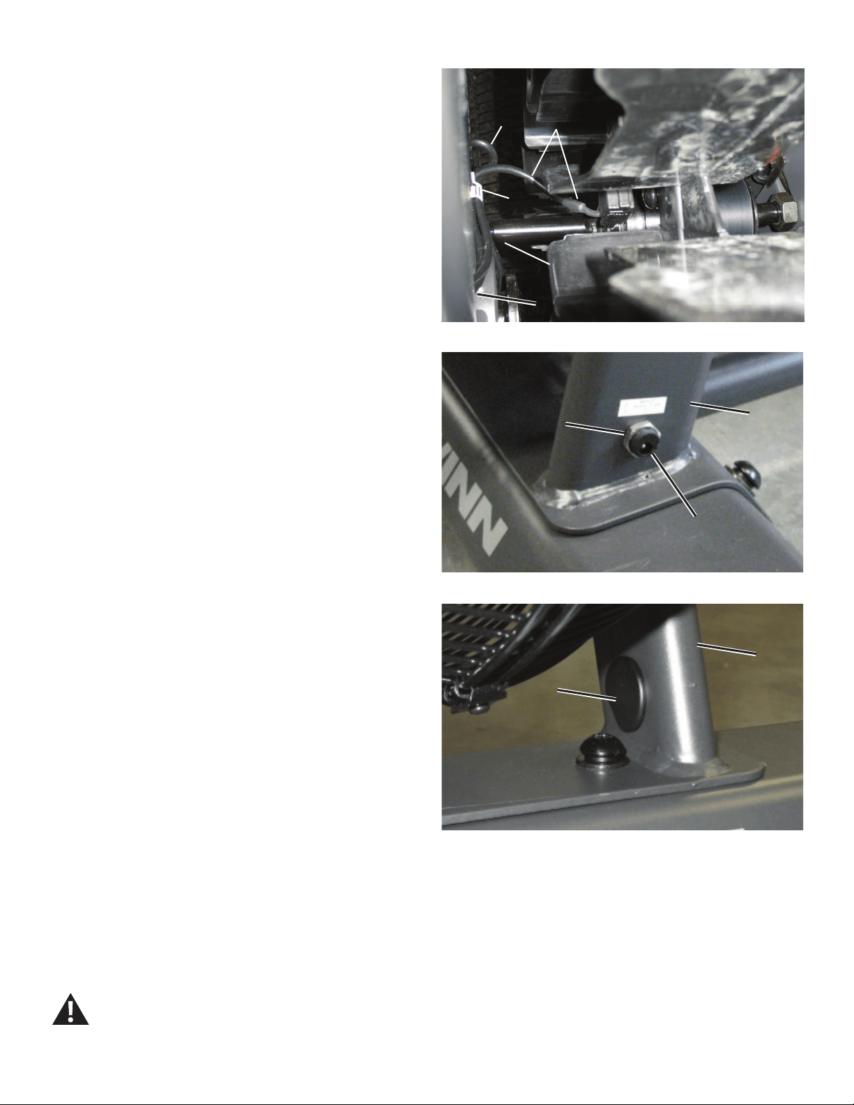
63
7. Carefully open the cable clip (B) on the inside Frame Upright (E) to
release the Power Inlet cable (A) and the RPM Data cable (C). Hold the
Power Inlet cable at the Fan shaft (D) and carefully pull it out of the upper
part of the Frame Upright so that the string extends through the tube.
NOTICE: Do not crimp the RPM Data cable (C). Hold the end of the
RPM Data cable at the top of the Frame Upright so that it is
not pulled down into the upright.
8. Loosen and remove the Nut (F) from the Power Inlet plug (G) on
theoutsideoftheFrameUpright.Removetheatplasticplug(H)from
the inner side of the Upright tube and set it aside for reassembly. Hold
the Power Inlet assembly at the base of the Upright and carefully pull the
cable out through the hole in the inner side of the tube so that the string
extends through the entire length of the Upright.
NOTICE: Do not crimp the cables.
9. Untie the string from the old Power Inlet cable and discard the old
Power Inlet assembly.
10. Tie the string end at the base of the Frame Upright to the connector
end of the replacement Power Inlet assembly (A). Hold the string at the
Fan shaft (D) and carefully pull the new Power Inlet cable through the hole
in the inner side of the Upright tube (E) and the lower part of the tube, and
then through the upper part. To keep the cables clear of the Fan, carefully
secure the RPM Data Cable (C) and a loop of the Power Inlet cable (A) in
the cable clip (B) on the Frame Upright.
NOTICE: Do not crimp the cables. Be sure the routing for the cables
is correct to prevent interference from moving parts.
11. Untie the string from the Power Inlet cable, and connect the cables
from the Frame to the cables from the Console/Mast assembly.
Note: Do not let the cables fall down inside the Mast.
NOTICE: Do not crimp the cables. This step may require two people.
12. Put the Mast in position on the Frame and reinstall the hardware.
NOTICE: Be sure not to crimp any cables. This step may require two
people.
13. Push the Power Inlet plug (G) into the hole and tighten the Nut (F).
Reinstall the plastic plug (H) on the inner side of the Upright tube (E).
NOTICE: Do not crimp any cables. Be sure the Power Inlet plug is
seated evenly in the hole.
14. Final Inspection
Inspect your machine to ensure that all hardware is tight and components
are properly assembled.
Do not use until the machine has been fully assembled and
inspected for correct performance in accordance with the
Owner’s Manual.
Cable clip and Power Inlet cable (top view)
CA
B
DD
E
GG
FFEE
HH
EE