Loading ...
Loading ...
Loading ...
12
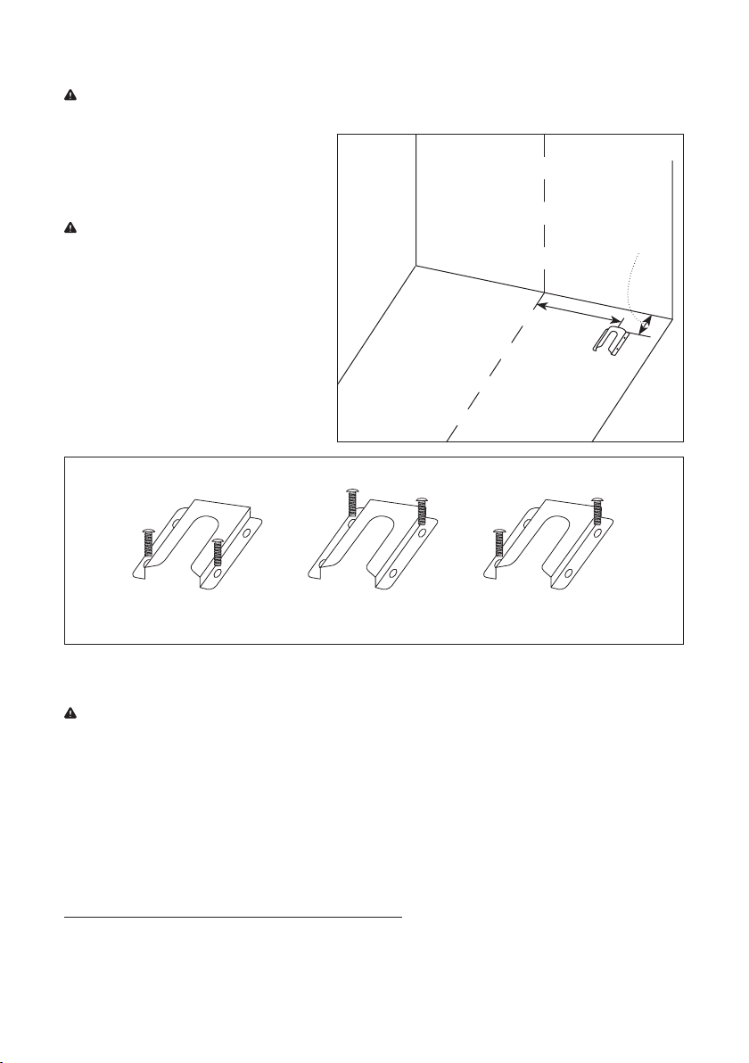
Figure 10
Figure 11
• Failure to follow these instructions can result in death or serious burns to children and adults.
IMPORTANT: DO NOT completely remove the rear leveling leg. The anti-tip bracket uses either the right-hand
or left hand, rear leveling leg to secure the range to the floor.
1. Remove the anti-tip bracket from where
it is taped inside the range.
2. Determine and mark the centerline of the
opening. (Refer to Figure 10.)
NOTE: The anti-tip bracket can be installed
on either side of the opening (left or right).
3. Measure 17 ½” (53.5cm) out from the
centerline and 5” (12.7cm) out from the
back wall. (Refer to Figure 10.)
4. Drill two 1/8” (3mm) holes through the
mounting holes in the anti-tip bracket
and into the floor.
5. Using the two screws provided, secure
the anti-tip bracket to the floor. (Refer to
Figure 11 for 3 different securing options.)
17-1/2”
(53.5cm)
5” (12.7cm)
Front Position Rear Position Diagonal Position
HOW TO CONNECT GAS LINE
WARNING: Explosion Hazard
• Use a new CSA International approved gas supply line.
• Install a shut-off valve.
• Securely tighten all gas connection.
• If connected to LP, have a qualified technician make sure gas pressure does not exceed 14” (36cm) water
column.
• Examples of a qualified technician include: licensed heating personnel, authorized gas company personnel,
and authorized service personnel.
• Failure to do so can result in death, explosion or fire.
How to Install Typical Flexible Connection (Refer to Figure 12.)
1. Apply pipe-joint compound made for use with NG (natural gas) to the male threads of the adapter.
2. Insert adapter into outlet of the gas pressure regulator, and then tighten using two 10” adjustable wrenches.
Be sure flow arrow on regulator is pointing up toward the range gas inlet pipe.
Loading ...
Loading ...
Loading ...