Loading ...
Loading ...
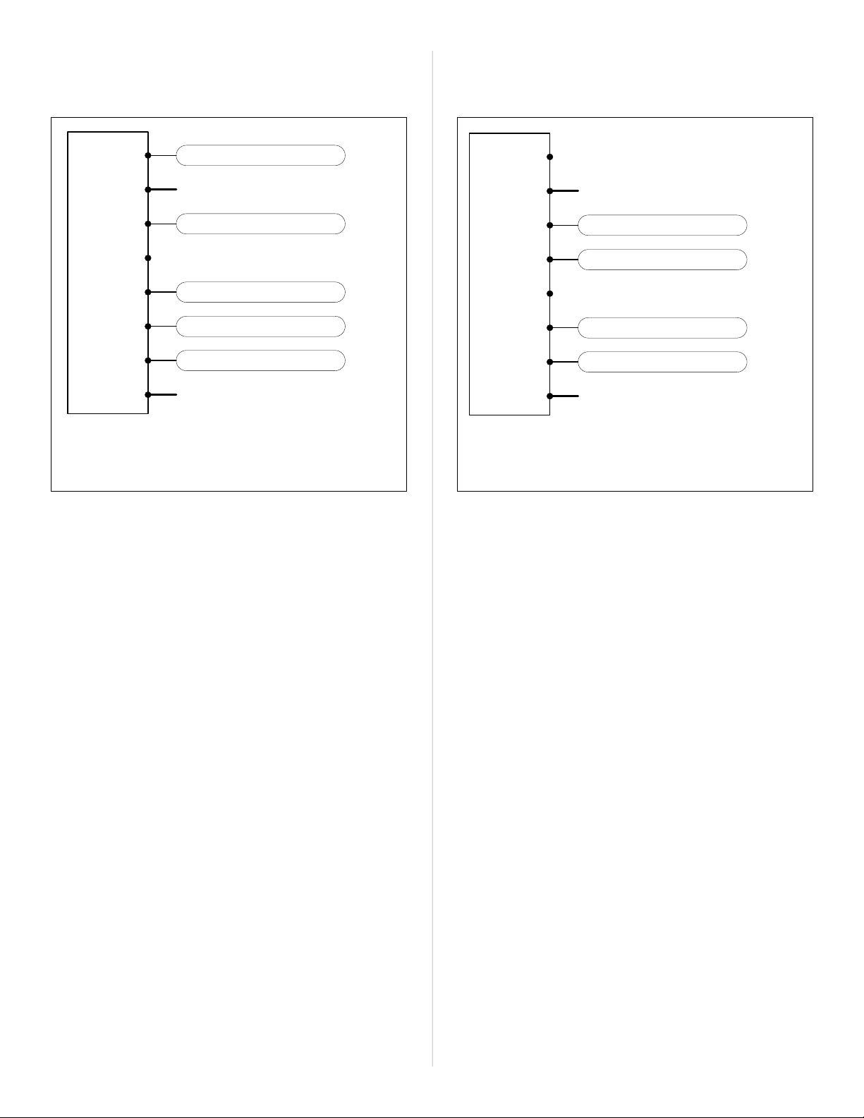
UP TO 1H/1C CONVENTIONAL APPLICATIONS:
(AMANA PTC PTAC MODELS) ** see note 1
B/O
R
Y
W1
W2
GH
GL
C
NOT USED
NOT USED
A/C Cooling
Blower Fan (High Speed)
Blower Fan (Low Speed)
AMANA PHWT-A200
THERMOSTAT
24V Power
Hea�ng Stage-1
24V Common
**see note 2
**see note 3
** CONVENTIONAL WIRING DIAGRAM NOTES:
• Note 1: For Conventional (cooling) PTAC units,
Installer Settings menu 06 (System Type) must be set
to “Con”.
• Note 2: If connecting to a Conventional PTAC unit
without electric heat, the W1 and W2 wire terminals
will not be used and Installer Settings menu 03
(Available Modes) should be set to “04: Cool Only”
• Note 3: For PTAC units with only one fan speed
(single “G” fan wire), use the “GL” terminal for wiring
and Installer Settings menu Item 12 (High Fan) must
be set to “OFF”.
7) WIRING DIAGRAMS
UP TO 2H/1C HEAT PUMP APPLICATIONS:
(AMANA PTH & HEH PTAC MODELS):
B/O
R
Y
W1
W2
GH
GL
C
HP Reversing Valve
Heat Pump Compressor
Blower Fan (High Speed)
Blower Fan (Low Speed)
AMANA PHWT-A200
THERMOSTAT
24V Power
Auxiliary/Emerg Heat
*see note 2
*see note 3
24V Common
NOT USED
*see note 1
* HEAT PUMP WIRING DIAGRAM NOTES:
• Note 1: When configured for Heat Pump operation,
the “Y” terminal will be called for during both cooling
and first-stage heating operation. Do not connect
any wires to the “W1” terminal.
• Note 2: The “W2” terminal is used to call for Electric/
Auxiliary heat. If your Heat Pump PTAC does not have
Electric heat, then the “W2” terminal should not
be used and Installer Settings menu 10 (Aux. Stage
Oset) should be set to “OFF”.
• Note 3: For PTAC units with only one fan speed
(single “G” fan wire), use the “GL” terminal for wiring
and Installer Settings menu 12 (High Fan) must be
set to "OFF".
*see note 1
*see note 2
*see note 3
**see note 3
**see note 2
Loading ...
Loading ...
Loading ...