taste of design
Piani cottura Lab
Manuale d’installazione e uso
Installation and use manual
PILB1203CZI
PILB481CZI
PILB4820ZI
PILB482MZI
PILB6040ZI
PILB902CZI
PILB904CZI
PALB1203CZI
PALB481CZI
PALB4820ZI
PALB482MZI
PALB6040ZI
PALB904CZI
PALB902CZI
PALBF1203CZI
PALBF481CZI
PALBF4820ZI
PALBF482MZI
PALBF6040ZI
PALBF902CZI
PALBF904CZI
2
Complimenti per aver acquistato una apparec-
chiatura Barazza!
Questa è un’apparecchiatura di grande qualità in
grado di accompagnarvi nel Vostro lavoro per lungo
tempo in modo affidabile e sicuro fornendo presta-
zioni di altissimo livello.
L’installazione e l’uso dell’apparecchiatura è semplice
e immediato.
Vi invitiamo a leggere attentamente questo manuale:
ciò permetterà un’ installazione e un utilizzo corretto
che manterrà la Vostra apparecchiatura sempre per-
fetta ed efficiente negli anni.
Per agevolare la lettura del manuale sono riportati i
seguenti simboli:
Prescrizioni importanti per la sicurezza perso-
nale e dell’apparecchiatura
Informazioni generali
Congratulations on purchasing a Barazza ap-
pliance!
This safe and reliable high-quality appliance can assist
you in your work with long-lasting top-level perform-
ance.
It also has the added advantage of being quick and
simple to install and easy to use.
Please read this manual carefully, as it provides im-
portant information for the correct installation and
use of the appliance which will ensure its long-term
efficiency.
The following symbols are used to assist you in reading
this manual:
Important rules for personal safety and the
safety of the appliance
General information
Il Costruttore si riserva di apportare ai propri prodotti e
a questo manuale le modiche che riterrà opportune senza ob-
bligo di preavviso. I disegni, gli schemi di installazione e le tabelle
contenuti all’interno del manuale sono da ritenersi indicativi ed
esclusivamente a titolo d’informazione.
Gli impianti di allacciamento dell’immobile devono rispettare le
normative nazionali vigenti.
É vietata la copia, la riproduzione parziale o totale dei conte-
nuti e l’inoltro di questo manuale a terzi senza il permesso del
Costruttore.
Questo apparecchio è conforme alle prescrizioni delle direttive
comunitarie CEE 87/308 del 2.6.87 (recepita con D.M. del 13.4.89)
sulla prevenzione ed eliminazione dei radiodisturbi, n. 89/336 sul-
la compatibilità elettromagnetica e 73/23 sulla bassa tensione.
Le istruzioni del presente libretto sono valide solamente per il
Paese di destinazione.
The manufacturer reserves the right to make any changes
deemed suitable to the product without prior notice.
The drawings, installation diagrams and tables contained in this
manual are approximate and for informational purposes only.
The systems for connecting the appliance must comply with current
national regulations.
The partial or complete reproduction or photocopying of the contents
of this manual IS forbidden, as well as the sending of this manual to
third parties, without the Manufacturer’s permission.
This appliance conforms to the EEC community guidelines 87/308
of 2.6.87 (acknowledged with Ministerial Decree of 13.4.89) on the
prevention and elimination of radio interference, no. 89/336 on
electromagnetic compatibility, 73/23 on low voltage.
The instructions in this booklet are valid only for the country of
destination.
3
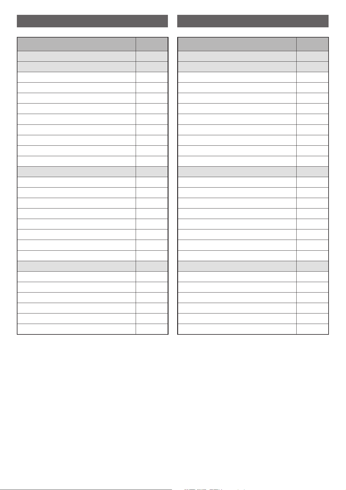
INDICE INDEX
DESCRIZIONE PAG.
DATI TECNICI 4
INSTALLAZIONE 7
Avvertenze di sicurezza 7
Controllo e movimentazione 8
Smaltimento degli imballi 8
Scelta del luogo di installazione 9
Collegamento elettrico 10
Collegamento gas 12
Regolazione minimo 14
Adattamento ad altri tipi di gas 15
Incasso apparecchiatura 16
USO 19
Avvertenze di sicurezza 19
Prima di cominciare 21
Conoscere l’apparecchiatura 21
Zona comandi 22
É bene sapere che 23
Uso dell’apparecchiatura 24
Uso dei bruciatori 24
Accessori 26
MANUTENZIONE 27
Avvertenze di sicurezza 27
Manutenzione ordinaria 28
Pulizia 28
Periodi di inattività 29
Smaltimento a ne vita 30
Assistenza post-vendita 30
DESCRIPTION PAGE
TECHNICAL DATA 4
INSTALLATION 7
Safety warnings 7
Checks and handling 8
Disposal of the packaging 8
Installation site choice 9
Connection to the power mains 10
Gas connection 12
Idle mode setting 14
Suitability with other gas types 15
Built-in unit installation 16
USAGE 19
Safety warnings 19
Before starting 21
Understanding the appliance 21
Control panel 22
Useful information 23
Using the appliance 24
Using the burners 24
Accessories 26
MAINTENANCE 27
Safety warnings 27
Routine maintenance 28
Cleaning 28
Periods of inactivity 29
End-of-life disposal 30
After-sales service 30
4
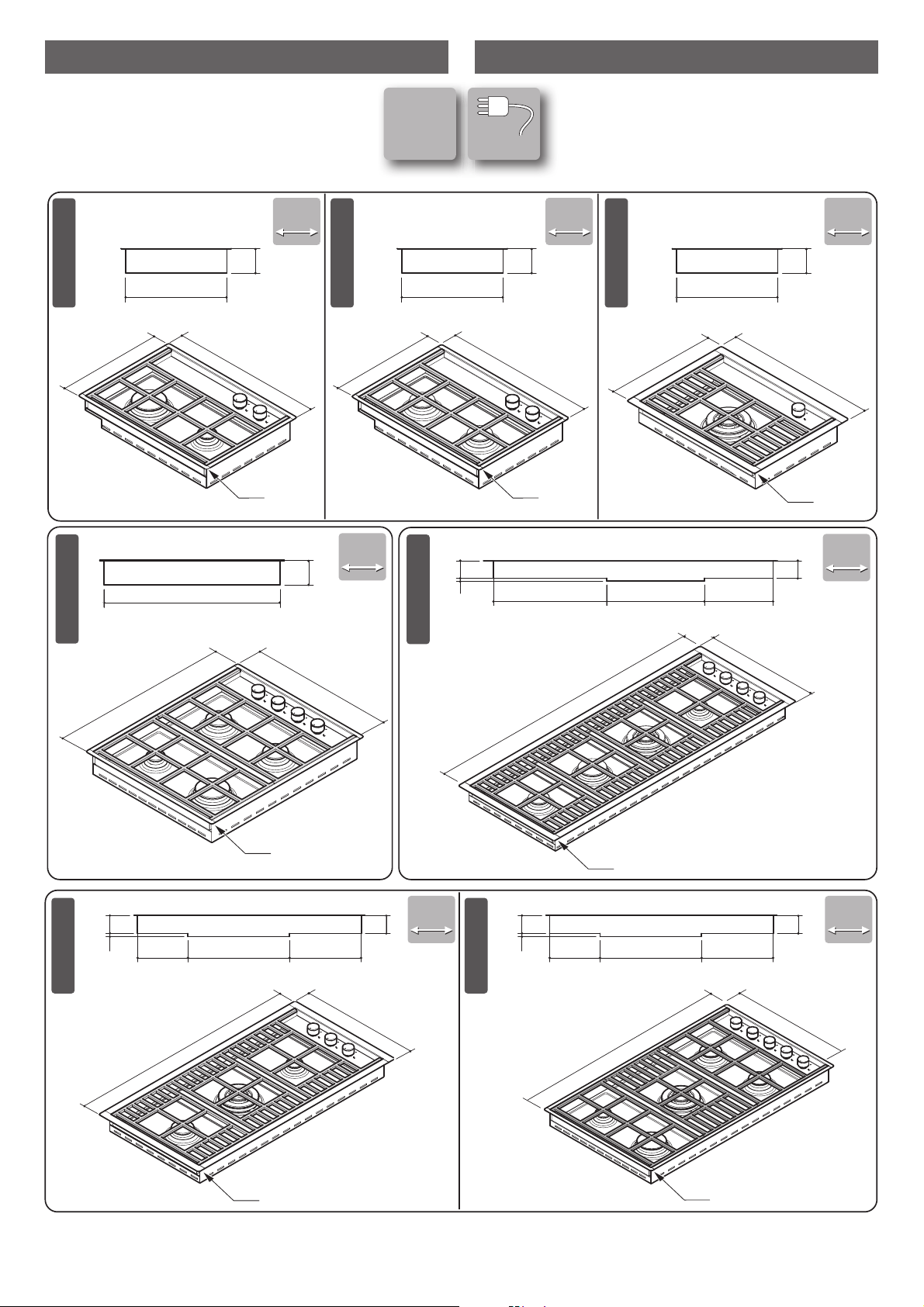
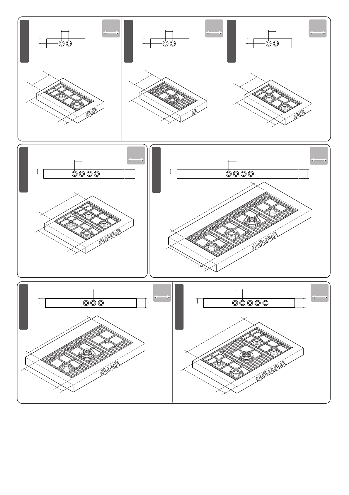
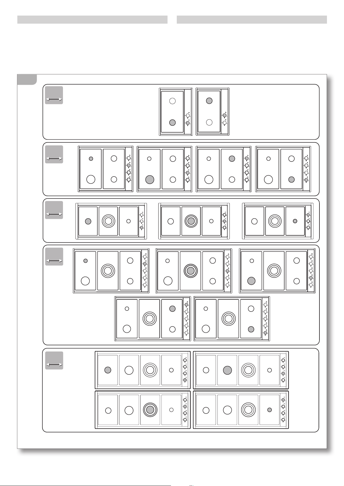
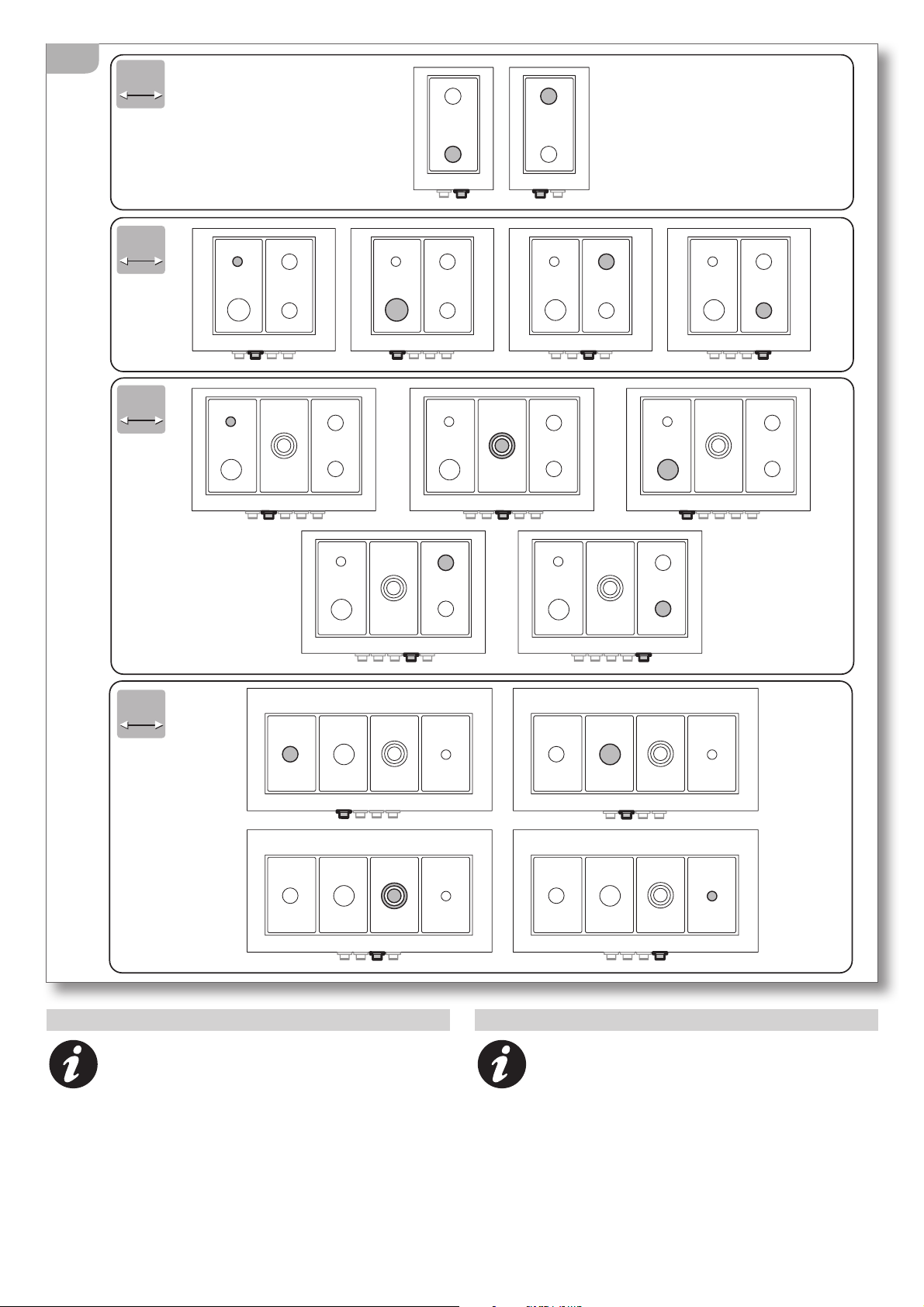
DATI TECNICI TECHNICAL DATA
Insulating
class
1
1
L=90cm
[mm]
[mm] [mm]
[mm]
[mm]
510
360
510
360
510
360
40
40
40
40
65
65
90
90
120
120
90
90
PILB902CZI
PILB1203CZI
PILB6040ZI
PILB904CZI
455
510
895
870
510
615
PILB4820ZI
PILB482MZI
40
40
PILB481CZI
332
80
587
80
332
80
332
80
[mm] [mm]
68
383
68
442 268
12
1150
455
382
68
190 270
6812
382
68
188 270
6812
R=6 R=6
R=6
R=6
R=6
R=6
R=6
With custom made models, dimensions
are made-to-order.
Nelle realizzazioni fuoriserie, le dimensio-
ni di ingombro sono “personalizzate”.
5
[mm]
[mm] [mm]
[mm]
[mm]
40
40
40
40
65
65
90
90
120
120
90
90
40
40
255
510
80
[mm] [mm]
40
80
80
40
80
80
40
80
80
40
80
480
255
48
0
80
765
1016
480
40
0
80
400
80
765
480
80
80
255
48
0
80
80
80
40
80
80
40
80
80
40
80
PALBF4820ZI
PALBF6040ZI
PALBF902CZI
PALBF904CZI
PALBF1203CZI
PALBF481CZI
PALBF482MZI
6
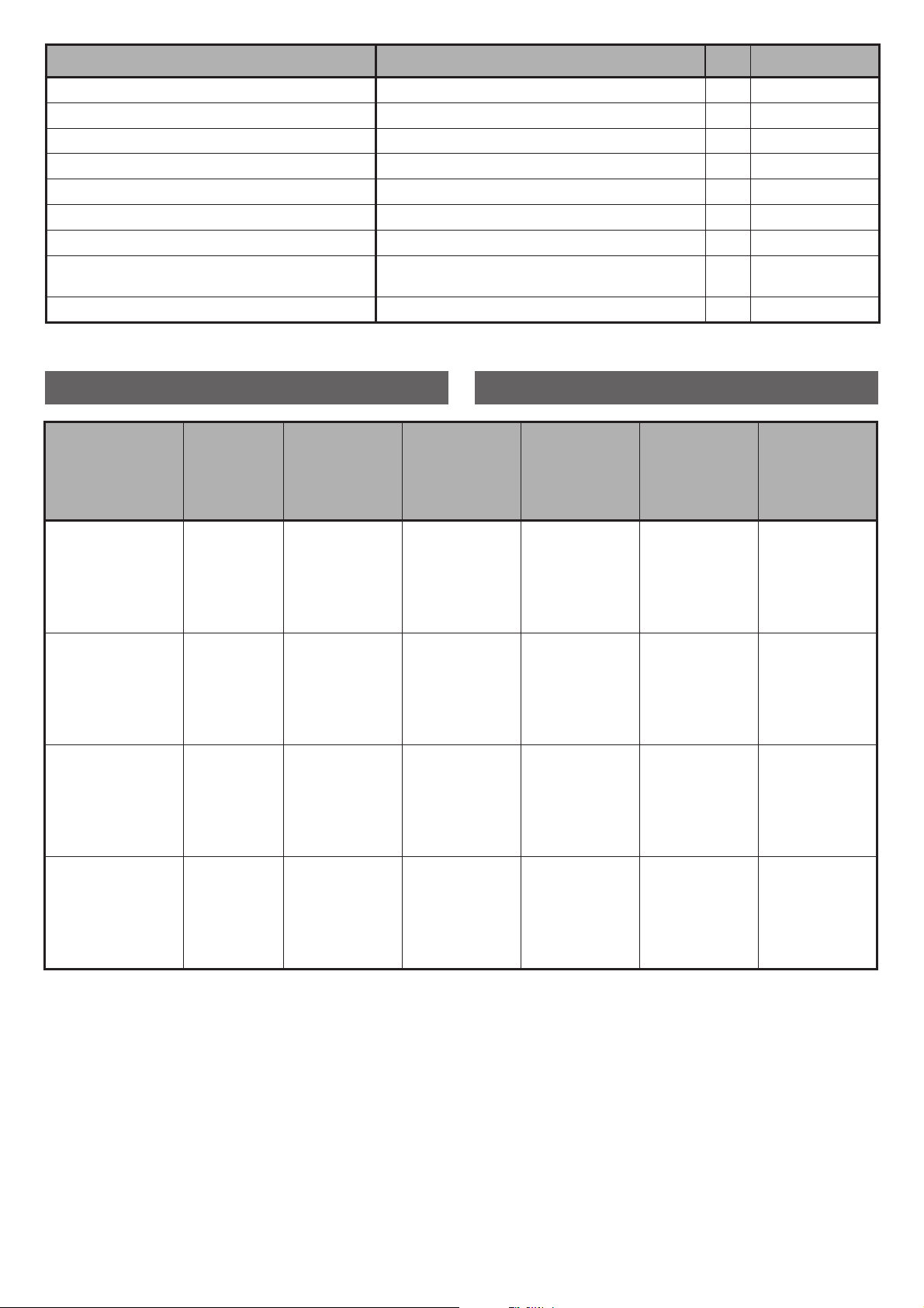
TABELLA UGELLI NOZZLE TABLE
Dati tecnici Technical data
Tensione Voltage V 220-230
Frequenza Frequency Hz 50
Potenza bruciatori Burner power
ausiliario auxiliary kW 1
semirapido semi- rapid kW 1,75
rapido rapid kW 3
tripla corona triple ring kW 3,3
Tipo cavo Cable type
H05RR-F
3x1 mm
2
Lunghezza cavo Cable length cm 90
Bruciatore
Burner
Tipo gas
Gas type
Pressione
d’esercizio
Applied
pressure
Portata
Capacity
ø Ugelli
1/100 mm
ø Nozzles
1/100 mm
Portata
nominale
Nominal
capacity
Portata
ridotta
Reduced
capacity
Ausiliario
Auxiliary
G30
G31
G30
G31
G20
G25
30 mbar
37 mbar
50 mbar
50 mbar
20 mbar
25 mbar
g/h 73
g/h 90
g/h 121
g/h 121
l/h 94
l/h 110
50
50
43
43
71
72
kW 1
kW 1
kW 1
kW 1
kW 1
kW 1
kW 0.45
kW 0.45
kW 0.45
kW 0.45
kW 0.45
kW 0.45
Semirapido
Semi- rapid
G30
G31
G30
G31
G20
G25
30 mbar
37 mbar
50 mbar
50 mbar
20 mbar
25 mbar
g/h 127
g/h 157
g/h 212
g/h 212
l/h 158
l/h 165
65
65
58
58
96
94
kW 1.75
kW 1.75
kW 1.75
kW 1.75
kW 1.75
kW 1.75
kW 0.45
kW 0.45
kW 0.45
kW 0.45
kW 0.45
kW 0.45
Rapido
Rapid
G30
G31
G30
G31
G20
G25
30 mbar
37 mbar
50 mbar
50 mbar
20 mbar
25 mbar
g/h 218
g/h 269
g/h 363
g/h 363
l/h 270
l/h 292
85
85
75
75
115
121
kW 3
kW 3
kW 3
kW 3
kW 3
kW 3
kW 0.85
kW 0.85
kW 0.85
kW 0.85
kW 0.85
kW 0.85
Tripla corona
Triple ring
G30
G31
G30
G31
G20
G25
30 mbar
37 mbar
50 mbar
50 mbar
20 mbar
25 mbar
g/h 240
g/h 296
g/h 400
g/h 400
l/h 328
l/h 323
93
93
73
73
124
130
kW 3.3
kW 3.3
kW 3.3
kW 3.3
kW 3.3
kW 3.3
kW 1.40
kW 1.40
kW 1.40
kW 1.40
kW 1.40
kW 1.40
7
SAFETY WARNINGS
Read this instruction booklet carefully before instal-
lation and/or use of the appliance and keep it handy
so that all the users can consult it; if you give away or sell
the appliance, please ensure that you give this booklet
to the new user so that he can be informed about its
installation, use and safety rules.
The installation and any interventions on the
appliance (special maintenance, nozzle replacement,
idle mode setting, etc.) must be carried out by qualified
personnel only, as specified in this booklet.
The connection systems (gas and electric) and installa-
tion rooms must be suitable and satisfy the safety stand-
ards in force in the country of use (protective isolating
switch, earthing system, equipotential system, etc.).
The manufacturer will not be held liable if the above
requirements are not satisfied.
During installation, maintenance or repair work,
always switch off the main electrical switch, remove the
connection plug from the socket and shut off the gas
supply taps.
The appliance is not designed for outdoor use.
Appliances may have sharp edges; handle them
with caution and use personal safety equipment (protec-
tive shoes, safety gloves, etc.).
INSTALLAZIONE INSTALLATION
AVVERTENZE DI SICUREZZA
Leggere attentamente questo libretto di istruzioni
prima dell’installazione e/o dell’uso dell’appa-
recchiatura e conservarlo in un luogo accessibile a
tutti gli utilizzatori per consultazioni future; in caso di
cessione o vendita dell’apparecchiatura assicurarsi di
consegnare al nuovo utente anche questo libretto al
fine di conoscerne l’installazione, l’uso e le prescrizioni
di sicurezza.
L’installazione e gli interventi sulle apparec-
chiature (manutenzione straordinaria, sostituzione
degli ugelli, regolazione del minimo, ecc..) vanno
eseguiti solo da personale qualificato secondo
quanto specificato nel presente libretto.
Gli impianti di allacciamento (gas ed elettrico) e i locali
di installazione devono essere idonei e rispondere
alle norme di sicurezza in vigore nel Paese di utilizzo
(interruttore di protezione e separazione, impianto di
terra, equipotenziale, ecc.).
Il Costruttore non si ritiene responsabile qualora non
venga rispettato quanto sopra descritto.
Durante le operazioni di installazione, manu-
tenzione o riparazione spegnere sempre l’interruttore
elettrico principale, staccare la spina di collegamento
e chiudere i rubinetti di alimentazione gas.
L’apparecchiatura non è stata progettata per
il funzionamento all’aperto.
Le apparecchiature potrebbero avere i bordi
particolarmente taglienti, maneggiarle con attenzione
e opportune protezioni personali di sicurezza (scarpe
antiinfortunistica, guanti, ecc...).
8
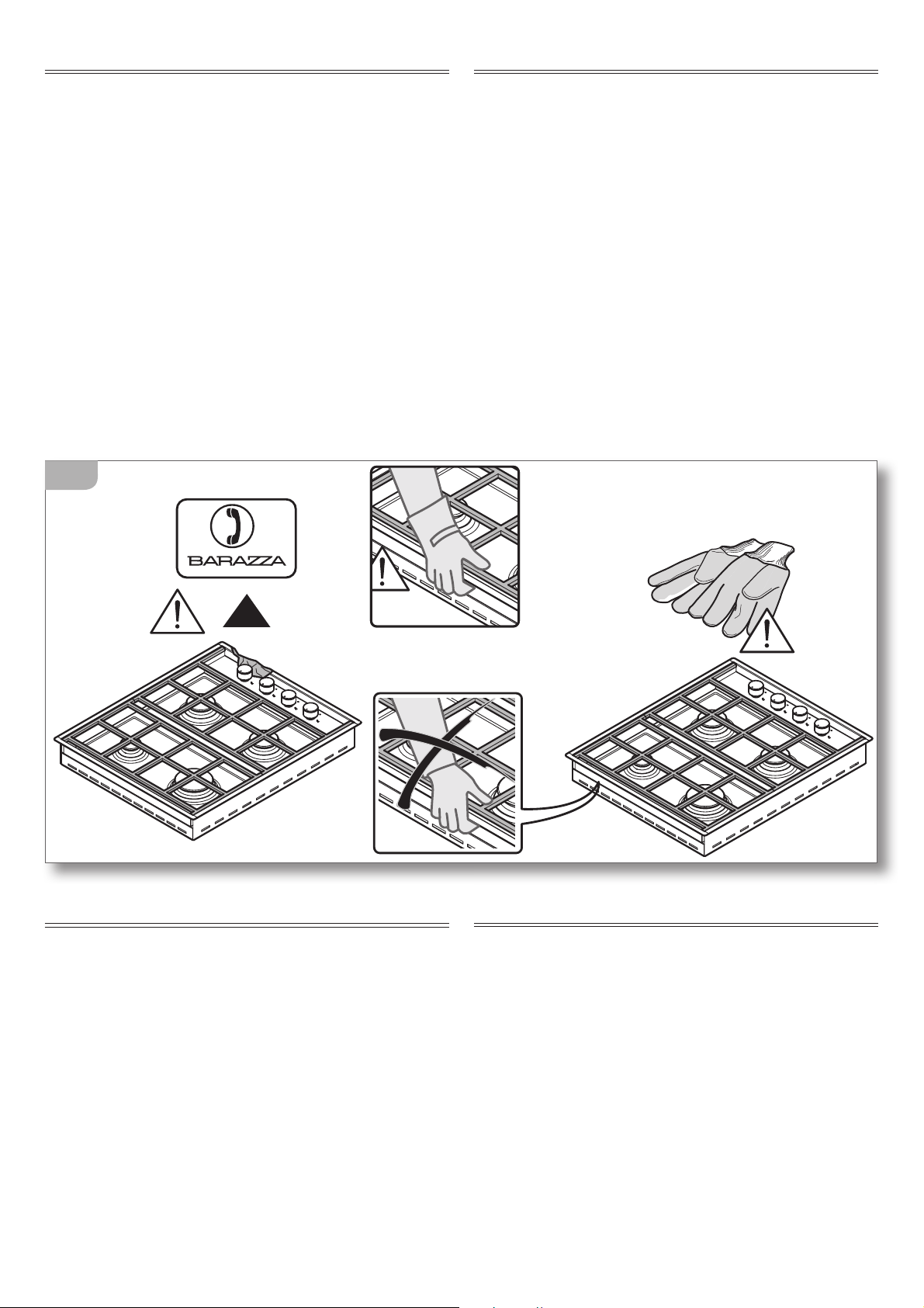
CHECKS AND HANDLING
After having unpacked the appliance and removed all
the packing materials and protective films from the sur-
faces, check for any anomalies: if you find an anomaly,
do not proceed with the installation but contact your
retailer within 8 days, reporting the data provided on
the appliance’s data plate and describing the problems
you found
(fig. 1).
Attention! Do not leave the packing materials (plas-
tic bags, polystyrene, etc.) unattended, as they are a
potential hazard for children and animals (danger
of suffocation).
Move the appliance to the installation location using
appropriate personal safety equipment
(figure 1) and
adopting all the precautions necessary to prevent dam-
age to the appliance, people, animals and property.
DISPOSAL OF THE PACKAGING
Attention! Dispose of the packaging in compliance
with current regulations in the country where the
appliance is installed.
Package composition:
- cardboard
- polyethylene / polypropylene: outer packaging film,
instructions bag
- expanded polystyrene: impact protections.
CONTROLLO E MOVIMENTAZIONE
Dopo aver disimballato l’apparecchiatura rimuovendo
tutti i materiali di imballo e le pellicole a protezione
delle superfici, controllare se si notano anomalie
evidenti: in caso affermativo, non procedere all’in-
stallazione e rivolgersi al Rivenditore entro 8 giorni,
comunicando i dati riportati nella targa matricola
dell’apparecchiatura ed i problemi riscontrati
(fig. 1).
Attenzione! Non lasciare incustodito il materiale
utilizzato per l’imballo (sacchetti, polistirolo, ecc...)
perché potenzialmente pericoloso per bambini e
animali (pericolo di soffocamento).
Trasportare l’apparecchiatura sul luogo dell’installa-
zione muniti di adeguate protezioni personali
(fig. 1)
e adottando tutte le precauzioni necessarie per non
arrecare danni all’apparecchiatura stessa, a persone,
animali e cose.
OK!
1
SMALTIMENTO DEGLI IMBALLI
Attenzione! Smaltire gli imballi in ottemperanza
alle normative vigenti nel Paese di installazione.
Composizione imballo:
- cartone
- polietilene / polipropilene: pellicola esterna imbal-
lo, sacchetto istruzioni
- polistirolo espanso: protezioni antiurto.
9
SCELTA DEL LUOGO DI INSTALLAZIONE
Caratteristiche del locale di installazione
Le apparecchiature devono essere posizionate in locali
interni idonei allo scopo con temperatura max. 25°C e
umidità max. 60%; essi devono rispondere alle norme di
sicurezza in vigore nel Paese di utilizzo (interruttore di
protezione e separazione, impianto di terra, equipoten-
ziale, ecc.). Le apparecchiature non sono adatte all’instal-
lazione all’aperto, esposte agli agenti atmosferici o alle
intemperie. Le apparecchiature possono essere montate
su mobili il cui materiale sia resistente al calore (120°C).
I locali di installazione devono aver un con-
tinuo ricambio d’aria affinchè possa sempre affluire
l’aria necessaria alla combustione del gas, secondo
quanto previsto dalle norme in vigore UNI – CIG 7129
e 7131. Le aperture con sezione di almeno 100 cm
2
de-
vono essere costruite in modo che non possano venire
ostruite ne dall’interno ne dall’esterno e devono essere
posizionate vicino al pavimento (fig. 2). Ogni altra for-
ma di ventilazione deve necessariamente rispondere a
quanto previsto nella norma UNI – CIG 7129.
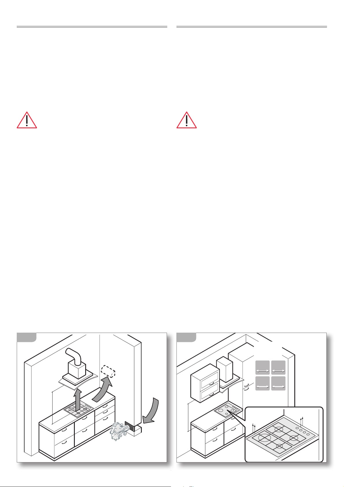
Scarico fumi
Le apparecchiature a gas devono scaricare i prodotti
della combustione direttamente all’esterno attraverso
canne fumarie, mediante cappe di aspirazione o elet-
troventilatori (UNI – CIG 7129) (
fig. 2) con una portata
tale da garantire un ricambio orario d’aria di almeno 3
volte il volume del locale. Si ricorda che l’aria necessa-
ria alla combustione è di 2m
3
/h per ogni kW di portata
termica nominale (fare riferimento alla targhetta ma-
tricola per il totale della portata termica).
Distanza dalle pareti laterali e posteriori
Le apparecchiature devono essere tenute ad una
determinata distanza dalle pareti (
fig. 3).
9
AIR
AIR
AIR
min.
70 cm
2
INSTALLATION SITE CHOICE
Installation site characteristics
The appliances must be placed in suitable interior loca-
tions with a maximum temperature of 25°C and maximum
humidity of 60%; the locations must satisfy the safety
standards in force in the country of use (protective isolat-
ing switch, earthing system, equipotential system, etc.).
The appliances are not designed for outdoor use, to be
exposed to the elements or bad weather conditions. Appli-
ances may be assembled onto units made of heat-resistant
materials (120°C).
Installation locations must have continuous air
exchange to provide the air flow necessary for gas com-
bustion as specified in the standards in force UNI – CIG
7129 and 7131. Openings with an area of at least 100 cm
2
must be constructed in such a way so that they cannot be
obstructed from neither the inside or the outside and they
must be positioned in proximity to the ground (figure 2).
Every other ventilation type must be in accordance with
specifications in the standard UNI – CIG 7129.
Fume discharge outlet
Gas appliances must release the combustion emissions
directly outside via flues, either by using extractor hoods
or electric fans (UNI – CIG 7129) (
figure 2) with sufficient
power to guarantee hourly air exchange at least 3 times
the location volume. It is to be noted that 2m
3
/h of air
is necessary for every kW of nominal thermal capacity
(consult the data plate for total thermal capacity).
Distance from side and back walls
The appliances must be kept at a specified distance from
walls (
figure 3).
56 cm min.
A= 4 cm
B= 5 cm
40
40
65
65
90
90
120
120
A
B
3
10
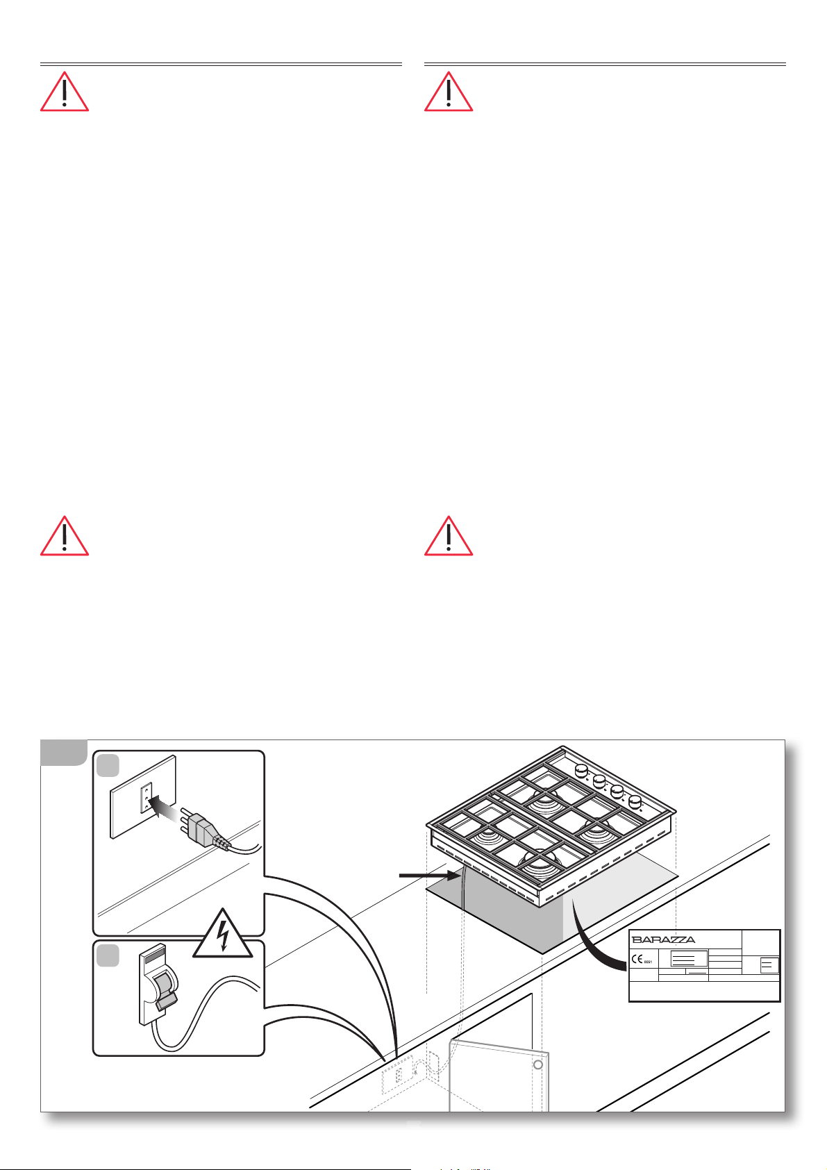
CONNECTION TO THE POWER MAINS
Before making the connection, make cer-
tain that the voltage and frequency indicated on
the data plate match those of the power supply
system.
The appliance is supplied with a 90cm-long power cord
(H05RR-F) on which a 10 A plug must be installed to then
be connected with a power outlet
(figure 4a).
Alternatively, the cable can be connected directly to
the distribution network
(figure 4b): in this case an om-
nipolar disconnecting switch must be provided, with a
minimum opening of the contacts that allows complete
disconnection in category III overvoltage conditions.
The isolating switch must be located in a position
which is accessible even after the appliance is in-
stalled.
If the appliance is installed together with an oven, the
connection of the two appliances must be independ-
ent for electrical safety reasons.
The power cord must NOT:
- be crushed or rolled up;
- come into contact with any type of liquid, sharp or hot
objects or corrosive substances;
- reach, at any point, a temperature which is 50°C higher
than the room temperature;
- be replaced with a different type of cable (see “Technical
data” on p. 6)
or with a cable which is not up to standard;
- be lengthened with extensions.
COLLEGAMENTO ELETTRICO
Prima dell’allacciamento accertarsi che la
tensione e la frequenza riportate sulla targhetta
caratteristiche corrispondano a quelle dell’impian-
to di alimentazione.
L’apparecchiatura viene fornita già provvista di un
cavo di alimentazione (H05RR-F) lungo 90 cm sul quale
dovrà essere installata una spina che sopporti i 10 A da
collegare infine a una presa di corrente
(fig. 4a).
In alternativa è possibile collegare il cavo direttamente
alla rete di distribuzione (fig. 4b): in questo caso deve
essere previsto un dispositivo per la disconnessione
onnipolare con una distanza di apertura dei contatti
che consenta la disconnessione completa nelle con-
dizioni della categoria di sovratensione III.
Sia la presa di corrente che l’interruttore onnipolare
devono essere a norma e collocati in posizione ac-
cessibile anche con l’apparecchiatura incassata.
Se l’apparecchiatura viene inserita in abbinamento
a un forno, l’allacciamento delle due apparec-
chiature deve essere indipendente per motivi di
sicurezza elettrica.
Il cavo di alimentazione NON deve:
- essere schiacciato o arrotolato su se stesso;
- entrare in contatto con liquidi di qualsiasi tipo,
oggetti taglienti o caldi e sostanze corrosive;
- raggiungere in nessun punto una temperatura che
superi di 50°C la temperatura ambiente;
- essere sostituito con uno di tipo diverso
(vedi “Dati
tecnici” pag. 6)
o non a norma;
- essere allungato con prolunghe.
10
H05RR-F
3x1mm
2
90 cm
10A
B
A
G30 - 28 mbar
220V-240V 50HZ
0,000 Kw
G20 - 20 mbar
Questo apparecchio deve essere installato conformemente alle norme in
vigore e utilizzato solamente in locale ben areato. Consultare il libretto
istruzioni
p
rima di installare e usare l'a
p
arecchio.
REGOLATO A
GAS
G20
N°: XXXXXXXXX
CATEGORIA II 2H3+ IT
F.lli BARAZZA s.r.l.
MADE IN ITALY
Qn
g/h
00.0 kW
000
g/h
XXXXX
XXXXX
XXXXX
MOD
ART
N°
istruzioni
prima
di
installare
e
usare
l aparecchio
.
4
11
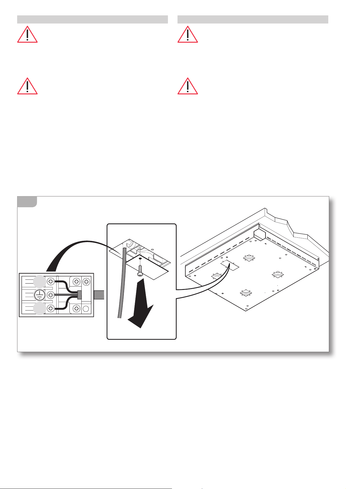
SOSTITUZIONE DEL CAVO DI ALIMENTAZIONE
In caso di necessità, il cavo di alimentazio-
ne può essere sostituito con uno di tipo identico
(vedi “Dati tecnici” pag. 6) in ottemperanza alle
normative vigenti nel Paese di installazione.
Se l’apparecchiatura è già collegata,
staccarla dall’alimentazione elettrica e chiudere
i rubinetti di intercettazione del gas.
Per accedere ai collegamenti elettrici, togliere il
coperchietto della morsettiera svitando la vite che
lo blocca (fig. 5).
Staccare il vecchio cavo dai morsetti e rimuoverlo;
collegare il nuovo cavo (unicamente di tipo H05RR-F)
nei rispettivi morsetti, N - L - Terra.
Bloccare il nuovo cavo con l’apposito passacavo
e richiudere la morsettiera riposizionando il suo
coperchio.
N
L
5
POWER CORD REPLACEMENT
If necessary, the power cord can be replaced
with an identical type
(see “Technical data” on page
6)
in compliance with current regulations in the
country where the appliance is installed.
If the appliance is already connected,
disconnect the electrical power and shut off gas
supply taps.
To access the electrical connections, remove the cover
from the terminal board by unscrewing the screws
(figure 5).
Disconnect the old cord from the terminals and remove
it; connect the new cord (only the H05RR-F type) into the
respective terminals N - L - Earth.
Cover the new cord with the appropriate cord holder and
re-close the terminal, replacing its cover.
12
COLLEGAMENTO GAS
Prima dell’allacciamento accertarsi che
tutto l’impianto gas e i locali di installazione siano
in accordo con le normative vigenti nel Paese di
utilizzo (UNI-CIG 7129 e 7131).
- Accertarsi che la linea di alimentazione sia libera
da ostruzioni e di portata sufficiente ad assicurare
il corretto funzionamento dell’apparecchiatura.
- Accertarsi che sulla linea di alimentazione, in luogo
facilmente accessibile ed ispezionabile, sia inserito
un rubinetto di intercettazione del gas: esso dovrà
essere chiuso durante le operazioni di installazione
e manutenzione dell’apparecchiatura.
-
Verificare il tipo di gas con il quale sarà alimentata
l’apparecchiatura (Gas liquido G30/G31 oppure Metano
G20/25) e controllare che l‘ apparecchiatura sia predi-
sposto per quel tipo di alimentazione: in caso contrario
adattarlo seguendo le indicazioni riportate nel paragra-
fo
“Adattamento ad altri tipi di gas” a pag.15.
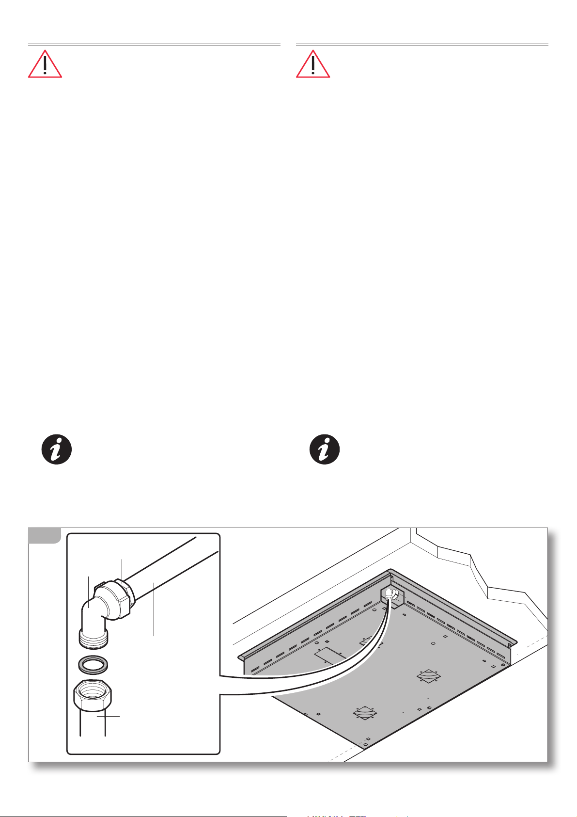
- Procedere all’allacciamento: (fig. 6) sulla rampa di
alimentazione “A” è montato un raccordo a gomito
“L” (filetto GJ ½”) che consente l’allacciamento alla
rete di distribuzione tramite un tubo rigido (norma
UNI-CIG 7129) oppure un tubo flessibile di acciaio
inox a parete continua (norma UNI-CIG 9891).
Il collegamento con il tubo rigido o flessibile deve
garantire la tenuta tramite la guarnizione “G2”.
Il raccordo di allacciamento “L” può essere
orientato allentando il dado “B” e poi, ese-
guita l’operazione di orientamento, bloccan-
do nuovamente il dado. La tenuta è garantita dalla
forma particolare della rampa e dalla guarnizione
interna.
A
L
(GJ ½)
B
G2
UNI-CIG 9891
UNI-CIG 7129
6
GAS CONNECTION
Before connecting the appliance, ensure that
the gas system and the installation locations comply
with current regulations in the country where the
appliance is installed (UNI-CIG 7129 and 7131).
- Ensure that the supply line is not obstructed and has
sufficient power to ensure correct operation of the
appliance.
- Ensure that the supply line, which should be located
in an easily accessible and visible location, has a gas
shut-off valve: this should be closed during appliance
installation and maintenance operations.
-
Check the gas type which will power the appliance
(Liquid Gas G30/G31 or Methane G20/25) and ensure
that the appliance is compatible with this: in the case
where it is not compatible, adapt it as instructed in the
paragraph
“Adaptation to other gas types” on page
15
.
- Proceed with connecting the appliance: (figure 6)
an L-shaped rubber connector (thread GJ ½”) is as-
sembled to power ramp “A”; this ensures connection
to the distribution network via a solid pipe (standard
UNI-CIG 7129) or a flexible stainless steel pipe flush
with the wall (standard UNI-CIG 9891).
Connection to the solid or flexible pipe is guaranteed
by using sealant “G2” to secure attachment.
The L-shaped connector can be positioned by
loosening the “B” nut and then, once posi-
tioned, re-tightening the nut. The specific form
of the ramp and the inner sealant guarantee attach-
ment.
13
Qualora la pressione del gas sia poco stabile,
installare a monte dell’apparecchiatura un regola-
tore di pressione del gas (se l’apparecchiatura deve
funzionare a gas liquido (G30 o G31), utilizzare
esclusivamente un regolatore di pressione confor-
me alla norma UNI-CIG 7432 (30 mbar).
Ad installazione ultimata, controllare la
perfetta tenuta di tutti i raccordi utilizzando una
soluzione di acqua e sapone, NON fiamme libere!
Ad installazione ultimata, provate ad
accendere tutti i bruciatori (consultare
pag. 24)
e verificate che la fiamma sia regolare e stabile,
eventualmente procedere alla regolazione del
minimo come indicato a
pag. 14).
If the gas pressure is unstable and it runs on
liquid gas (G30 or G31), install, above the appliance,
a gas pressure regulator; only use a gas pressure
regulator which complies with the standard UNI-CIG
7432 (30 mbar).
Once you have completed the installation
process, check the perfect attachment of all con-
nections using a mixture of water and soap, NOT
naked flames!
Once you have completed the installation
process, attempt to switch on all the burners (consult
page 24) and check that the flame is steady and
stable. Once ready, proceed to the idle mode setting
stage as indicated on
page 14).
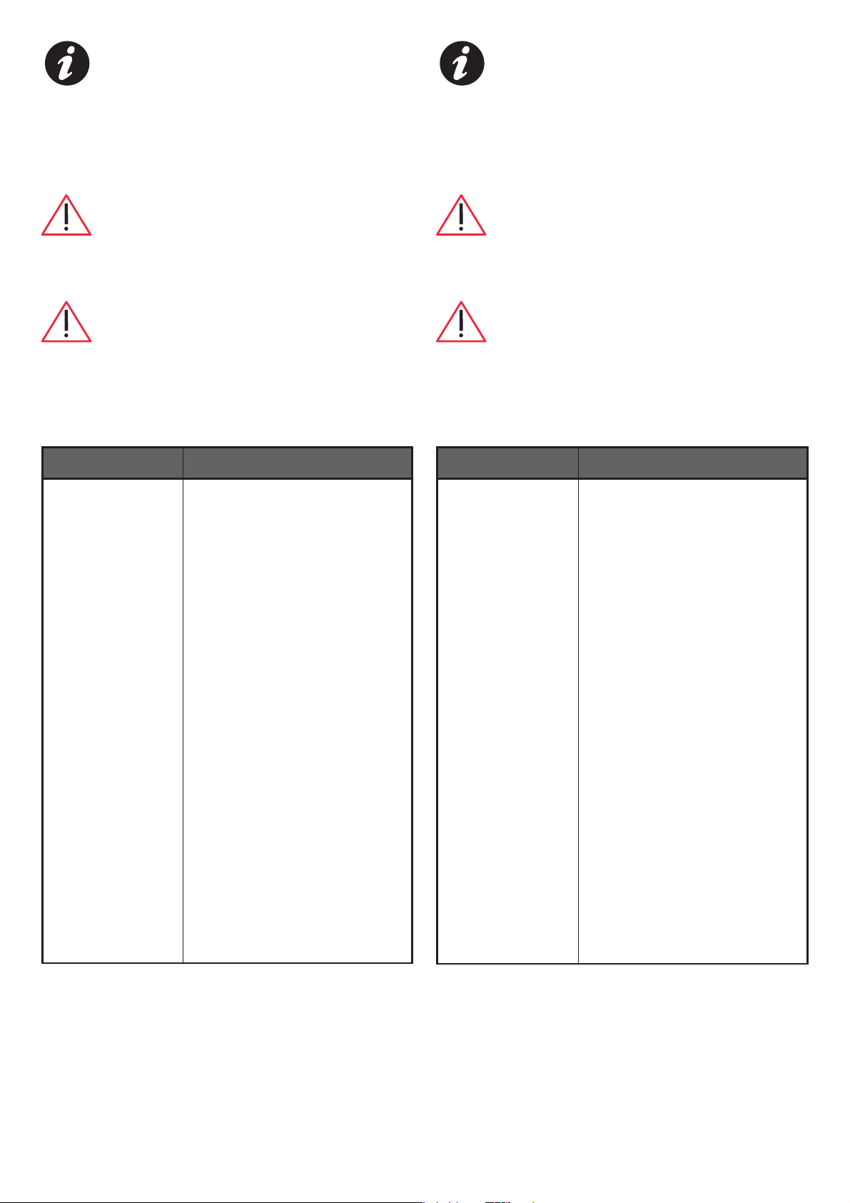
Problema: Soluzione
Il flusso del gas
sembra irrego-
lare
t $POUSPMMBSFDIFJMSVCJOFUUP
del gas sia aperto completa-
mente.
t $POUSPMMBSFDIFMBSFUFEJ
allacciamento abbia portata
adeguata.
t $POUSPMMBSFDIFHMJTQBSUJ-
fiamma e i bruciatori siano
posizionati correttamente e
siano liberi da ostruzioni.
t $POUSPMMBSFDIFHMJVHFMMJ
siano adatti al tipo di gas
utilizzato.
t $POUSPMMBSFMBDPSSFUUBUBSBUV-
ra del regolatore di pressione
se presente.
t $POUSPMMBSFJMUVCPEJBMJNFO-
tazione gas (tubo ostruito,
tubo piegato/schiacciato,
tubo eccessivamente lungo,
tubo inadatto, ecc...).
Problem: Solution
The gas flow seems
irregular
t$IFDLUIBUUIFHBTUBQJTGVMMZ
open.
t$IFDLUIBUUIFDPOOFDUJPOOFU-
work has a sufficient supply.
t$IFDLUIBUUIFGMBNFEJTUSJCV-
tors and the burners are cor-
rectly positioned and that they
are not obstructed.
t$IFDLUIBUUIFOP[[MFTBSFTVJU-
able for the gas type used.
t$IFDLUIBUUIFQSFTTVSFSFHV-
lator is correctly calibrated.
t$IFDLUIFHBTTVQQMZQJQF
(check that the pipe is not
obstructed, folded/crushed,
too long, unsuitable, etc...).
14
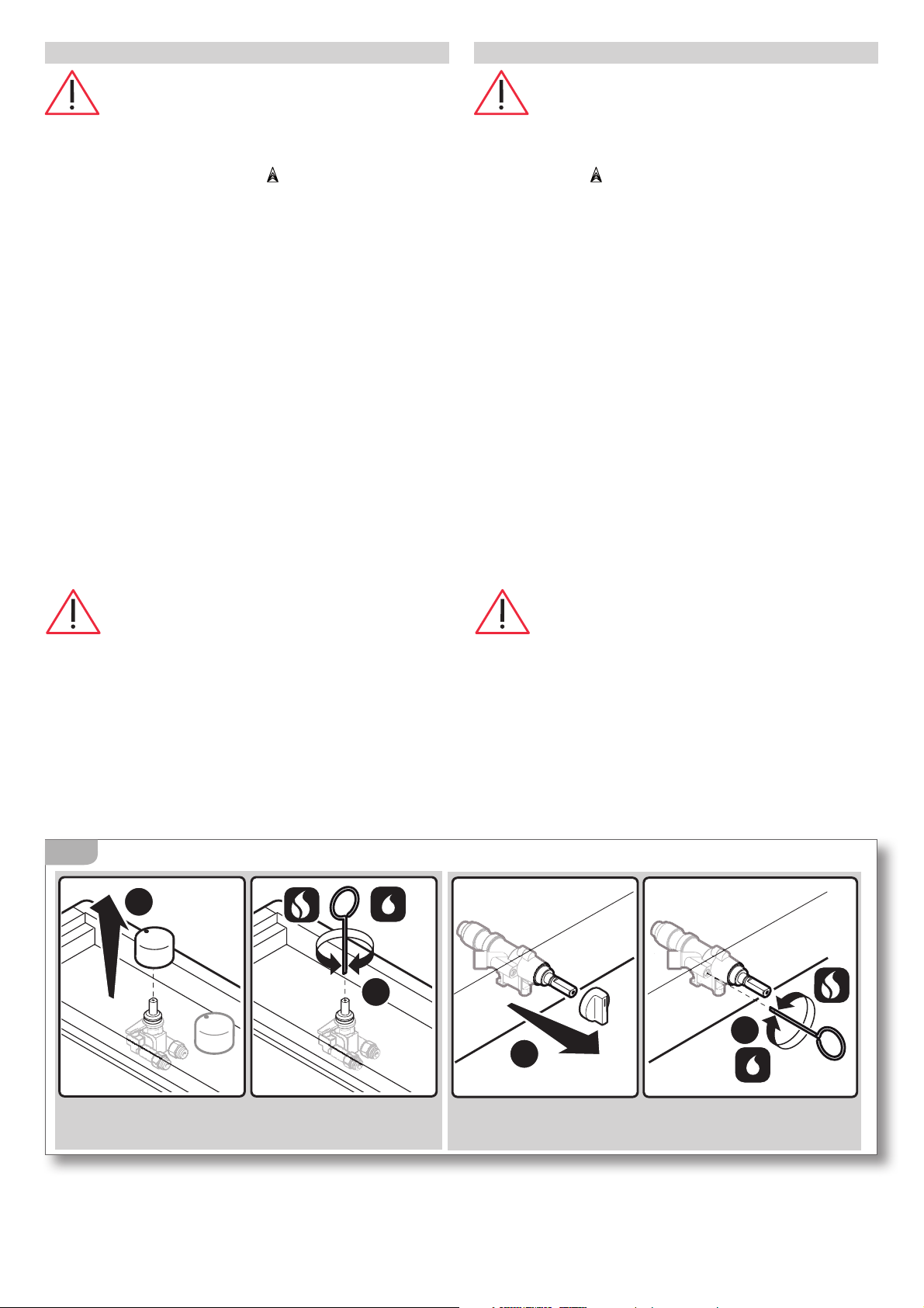
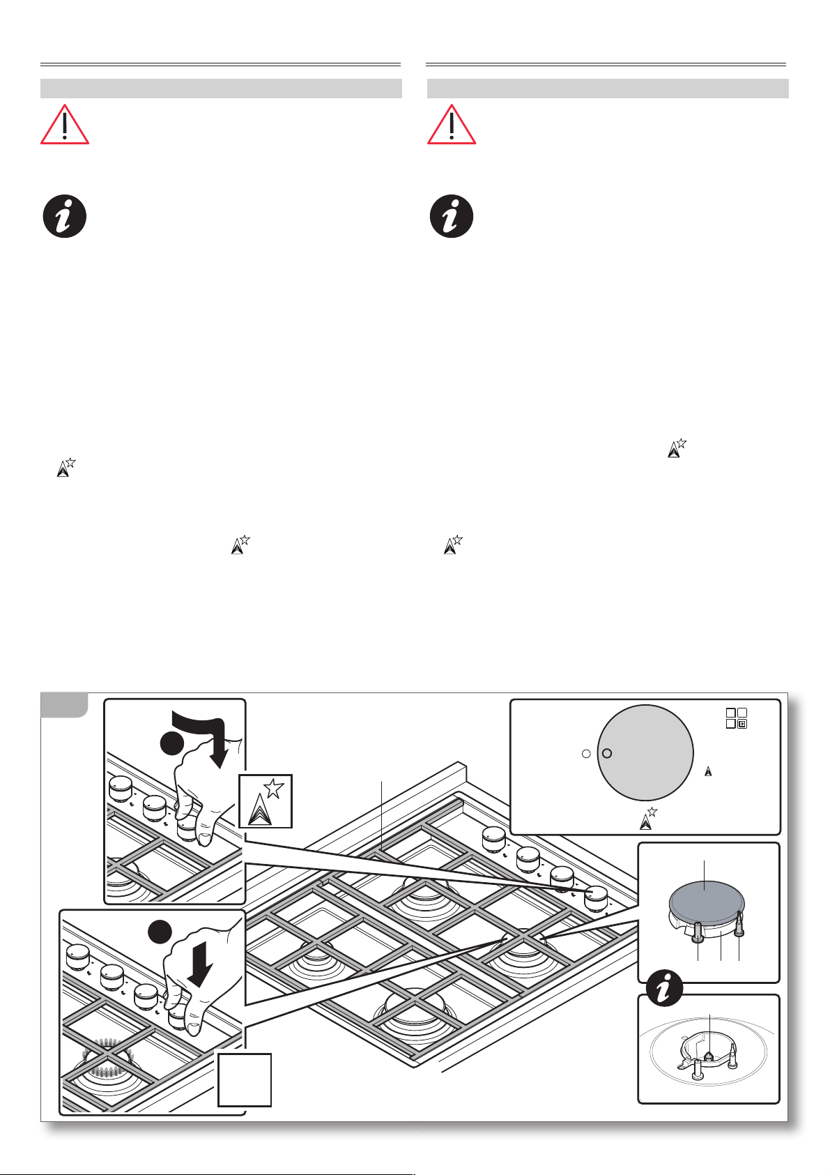
REGOLAZIONE DEL MINIMO
Effettuare la regolazione del minimo su un
bruciatore alla volta.
- Accendere un bruciatore e portare la manopola
nella posizione di minimo
.
- Sfilare la manopola corrispondente al bruciatore ac-
ceso fino a toglierla del tutto (fig. 7 - part.1); inserire
il cacciavite in dotazione nel foro al centro del perno
porta manopola: in fondo ad esso è localizzata una
vite di regolazione
(fig. 7 - part.2).
- Agire sulla vite, girandola verso destra per dimi-
nuire la fiamma o verso sinistra per aumentarla,
fino ad ottenere il minimo che si desidera.
In caso di funzionamento a gas liquido (G30/G31), la
vite di regolazione del minimo deve essere avvitata
completamente.
Nel caso dei piani con comandi sul bordo frontale,
la vite di regolazione è localizzata lateralmente al
perno porta manopola e si raggiunge attraverso il
foro predisposto a tale scopo
(fig. 7 - part.3-4).
- Rimontare le manopole con la massima cura accer-
tandosi di averle posizionate correttamente.
Al termine della regolazione verificare che:
1) non vi siano fughe di gas e che il funzionamento
dei bruciatori risulti corretto utilizzando una solu-
zione di acqua e sapone, NON fiamme libere!
2) ruotando rapidamente le manopole dalla
posizione di massimo a quella di minimo, non si
abbiano spegnimenti dei bruciatori. Eventualmente
aumentare la portata dei minimi stessi agendo sulla
vite di regolazione.
3
4
COMANDI FRONTALICOMANDI LATERALI
FRONT CONTROL PANELSIDE CONTROL PANEL
1
2
7
IDLE MODE SETTING
Set the idle mode on each burner one at a
time.
- Switch on a burner and bring the knob to the mini-
mum setting
.
- Turn the knob regulating the relevant burner until
the knob completely comes away (figure 7 - part 1);
insert the provided screwdriver in the centre of the
knob pivot hole: right inside the hole you will find an
adjustment screw
(figure 7 - part 2).
- Turn the screw towards the right to decrease the
flame or towards the left to increase the flame, in
order to ascertain the desired idle setting.
If powered by liquid gas (G30/G31), the adjustment
screw controlling the idle mode setting must be com-
pletely screwed in.
In the case of surface panels where the command
functions are at the front, the adjustment screw is
located to the side of the knob pivot hole and can
be reached via a hole specifically designed for this
purpose (figure 7 - parts 3-4).
- Replace the knobs with utmost care ensuring that you
have correctly positioned them.
Once you have completed the setting process,
check that:
1) there are no gas leaks and that the burners are
functioning correctly by using a mixture of water and
soap, NOT naked flames!
2) when rotating the knobs immediately from the
maximum to the minimum setting, that the burners
do not switch off. Increase the idle mode capacity
using the adjustment screws.
15
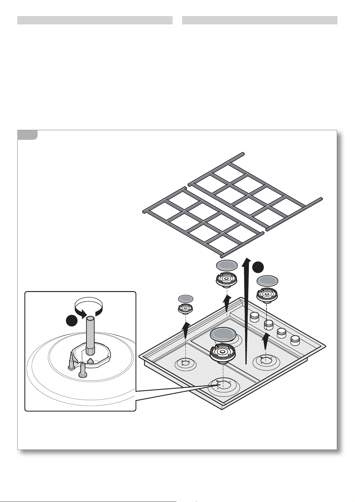
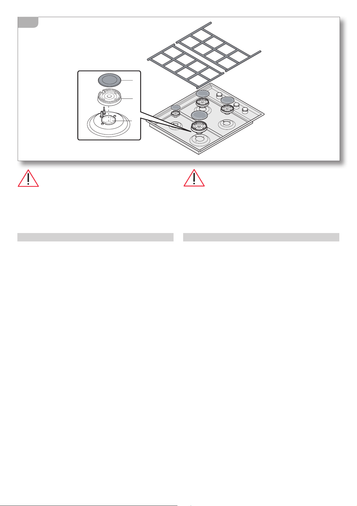
ADATTAMENTO AD ALTRI TIPI DI GAS
Togliere le griglie, gli spartifiamma e i bruciatori; con la
chiave in dotazione, togliere gli ugelli
(fig. 8) e sostitu-
irli con quelli allegati, rispettando scrupolosamente il
contrassegno e la tabella ugelli riportata a
pag. 6.
Nel caso si proceda alla regolazione dell’apparecchio
per un tipo di gas diverso da quello previsto all’origine,
in allegato alla documentazione vengono fornite due
nuove etichette da apporre, a cura dell’installatore,
sulla targhetta matricola dell’apparecchiatura e sulla
garanzia al fine di rendere riconoscibile e documen-
tata la nuova regolazione.
1
2
8
SUITABILITY WITH OTHER GAS TYPES
Remove the racks, the flame distributors and the burners;
with the spanner provided, remove the nozzles
(figure 8)
and replace them with the provided nozzles, carefully
checking the identification mark and the nozzle table
on
page 6. In the case where you carry out an appliance
regulation operation for a gas type that differs from
the above mentioned, appended to the present docu-
mentation, you will find two new stickers which must
be attached to both the appliance data plate and the
Guarantee by the person responsible for installation; the
stickers recognise and document the new regulation.
16
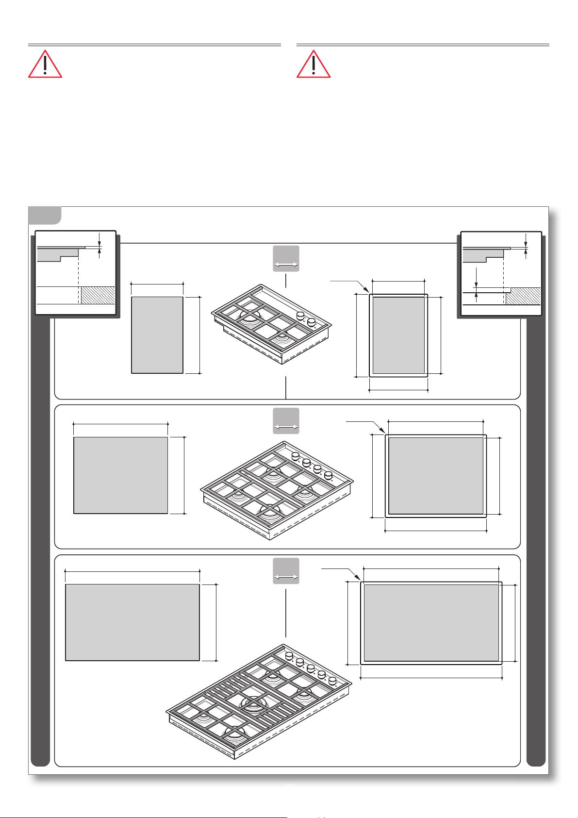
INCASSO APPARECCHIATURA
Accertarsi del perfetto stato e della stabilità
del mobile nel quale saranno incassate le apparec-
chiature (Normativa DIN 68930).
Preparare un foro di incasso con le misure indicate in fig.
9A-9B
; se l’apparecchiatura sarà incassata sopra un forno,
è necessario predisporre anche un pannello di separa-
zione (B) distante almeno 1 cm dal fondo della stessa,
forato nella parte posteriore per il passaggio del tubo gas
e dell’alimentazione elettrica dell’apparecchiatura.
16
[mm] [mm]
[mm] [mm]
Incasso / Built-in
Filo / Flush
40
40
65
65
1,2
1
1
[mm]
[mm]
340
490
595
490
850
490
513
618
595
490
R=7,5
513
873
850
490
R=7,5
[mm] [mm]
90
90
513
363
340
490
R=7,5
9A
BUILTIN UNIT INSTALLATION
Make certain that the cabinet in which you
will be installing the appliance is in perfect condition
and completely stable (Standard DIN 68930).
Prepare an embedded hole with measurements as specified
in
figures 9A-9B; if the appliance is to be installed above an
oven, it is also necessary to provide an isolating panel (B) with
a distance of at least 1 cm from the base of the appliance; the
isolating panel must be placed under the appliance to allow for
the gas pipe and the appliance’s supply of electrical power.
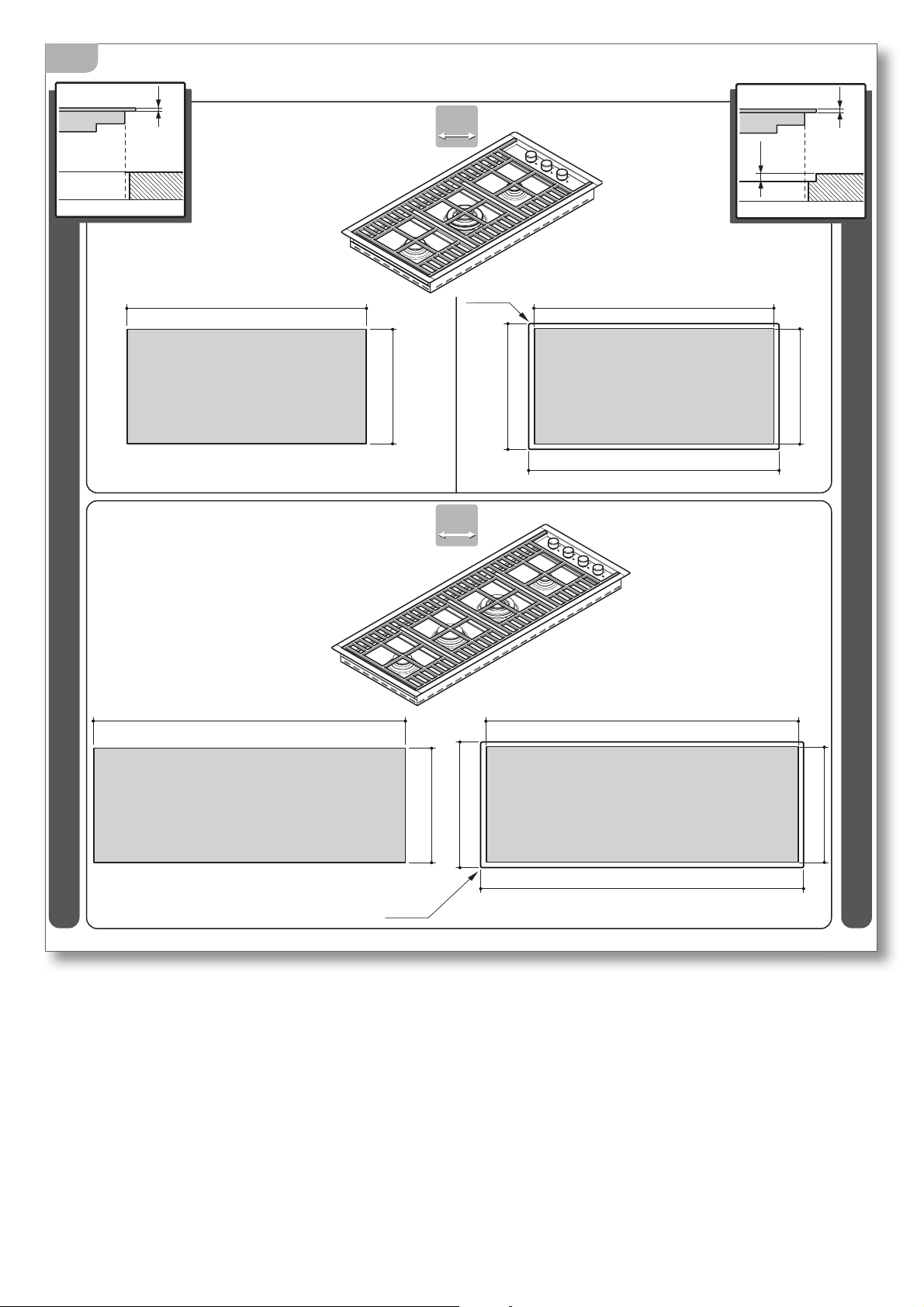
17
[mm] [mm]
90
90
875
435
458
898
875
435
R=7,5
[mm] [mm]
120
120
1130
435
458
1153
1130
435
R=7,5
Incasso / Built-in
Filo / Flush
1,2
1
1
[mm]
[mm]
9B
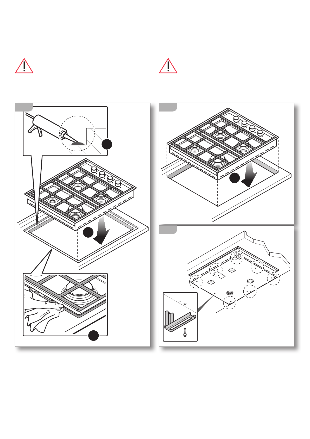
PIANI A FILO
Mettere sull’abbassamento del piano di lavoro del
silicone specifico per alte temperature (
fig. 10A part.
1)
,
successivamente sistemare l’apparecchiatura
sopra il foro di incasso spingendola contro il top (
fig.
10A - part. 2)
.
Il silicone precedentemente messo sull’abbassamento
del top per effetto dello schiacciamento riempirà anche
la fessura ai lati dell’apparecchiatura: p
ulire quello in
eccedenza (fig. 10A - part. 3).
Bloccare l’apparecchiatura con le viti e le staffe date
in dotazione (
fig. 11).
FLUSH PANELS
Put the high-temperature resistant silicone sealant on
the bottom of the work surface (figure 10A part 1),
sub-
sequently arrange the appliance on top of the embed-
ded hole lifting it so that it is just above the hole (
figure
10A - part 2)
.
The silicone sealant which was applied to the bottom of
the work surface, should also be applied to the gaps at the
sides of the appliance to prevent crushing: c
lean up any
excess silicone sealant (figure 10A - part 3).
Secure the appliance using the screws and brackets
provided (figure 11).
18
2
1
3
10A
1
10B
11
PIANI AD INCASSO
S
istemare l’apparecchiatura sopra il foro di incasso
spingendola contro il top (
fig. 10B - part. 1)
.
Bloccare l’apparecchiatura con le viti e le staffe date
in dotazione (
fig. 11).
Nelle realizzazioni fuoriserie il sistema di
fissaggio è personalizzato.
EMBEDDED SURFACES
S
ubsequently, arrange the appliance above the embed-
ded hole (
figure 10B - part 1)
.
Secure the appliance using the screws and brackets
provided (
figure 11).
With custom made models, assembly is
personalised.
19
USO USAGE
AVVERTENZE DI SICUREZZA
PER UN USO CORRETTO E SICURO
Questa apparecchiatura è stata concepita e
realizzata esclusivamente per la cottura degli alimenti.
Un uso diverso è considerato improprio e quindi po-
tenzialmente pericoloso per persone, animali e cose.
Inoltre potrebbe danneggiare irrimediabilmente l’ap-
parecchiatura: in questo caso il Costruttore non si ritiene
responsabile e non riconosce il diritto di Garanzia.
Spegnere sempre l’interruttore elettrico prin-
cipale, staccare la spina di collegamento e chiudere i
rubinetti di alimentazione gas prima di ogni operazio-
ne di pulizia o in previsione di lunga inattività.
Assicurarsi che tutte le manopole siano in
posizione “
- spento” al termine dell’utilizzo.
Se si dovesse notare una qualsiasi anomalia
non utilizzare l’apparecchiatura e contattare un Centro
di Assistenza autorizzato comunicando i dati presenti
nella targa matricola.
Questa apparecchiatura non è adatta all’uso da
parte di persone (inclusi i bambini) con difficoltà fisi-
che, sensoriali o mentali o con mancanza di esperienza
e conoscenza, a meno che una persona responsabile
della loro sicurezza fornisca a queste una supervisione
o un’istruzione riguardo l’uso dell’apparecchiatura.
I bambini devono essere sorvegliati per as-
sicurarsi che non giochino con l’apparecchiatura o
con parti di essa.
Pericolo di incendio!
Non utilizzare l’apparecchiatura come piano di ap-
poggio.
Pericolo di incendio!
Non posizionate mai oggetti sensibili al calore o
infiammabili (es. presine, tende, bottiglie di alcoolici,
ecc..) nelle vicinanze dell’apparecchiatura.
L’area nelle vicinanze dell’apparecchiatura
potrebbe essere molto calda, prestare cautela
nel posizionare in questo spazio prese di cor-
rente, altri elettrodomestici, cavi elettrici, tubazioni e
qualsiasi materiale sensibile al calore o infiammabile.
SAFETY WARNINGS
FOR SAFE AND CORRECT USE
This appliance has been designed and manufac-
tured exclusively for cooking food. Any other use is consid-
ered improper and thus potentially hazardous for people,
animals and property. Furthermore, it may permanently
damage the appliance: in this case, the Manufacturer will
not be held liable and the Guarantee will be void.
Always disconnect the appliance from the power
supply, remove the connection plug from the socket and
shut off gas supply taps before carrying out any cleaning
operations or when the appliance will not be used for an
extended period.
Make sure that all the knobs are turned to “ -
off” when you finish using the appliance.
If you should note any anomalies, do not use the
appliance but contact an authorized Service Centre and
report the data indicated on the data plate.
This appliance is not suited for use by persons
(including children) with physical, sensorial or mental
difficulties or lacking proper experience and knowledge,
unless supervised or instructed on the use of the appli-
ance by the person responsible for their safety.
Children must be supervised to ensure that they
do not play with the appliance or parts of it.
Fire hazard!
Do not use the appliance as a support surface.
Fire hazard!
Never place heat-sensitive and flammable objects (for
example, oven gloves, curtains, alcoholic containers,
etc..) near the appliance.
The area near the appliance may become very
hot, so take precautions when positioning
power outlets, other household appliances,
electrical cables, hoses and any heat-sensitive or flam-
mable material in this area.
20
PER LA COTTURA
Pericolo di scottature!
Durante il funzionamento e per alcuni minuti dopo
l’utilizzo, alcune parti dell’apparecchiatura raggiungono
temperature molto elevate! Non entrare in contatto con
queste parti senza protezioni personali adeguate.
Prima dell’utilizzo verificare che gli spartifiamma,
i bruciatori e la griglia siano correttamente posizionati.
In particolare controllare che la griglia appoggi corretta-
mente sull’apparecchiatura senza traballare.
Pericolo di incendio!
Non cucinate mai cibi alla fiamma.
Pericolo di incendio!
Nel caso di incendio del grasso o dell’olio caldo non
spegnere mai le fiamme con acqua ma soffocarle con
un canovaccio umido o similari e avvisare tempesti-
vamente i vigili del fuoco.
Pericolo di incendio!
Non rivestire l’apparecchiatura o parti di essa con fogli
di alluminio o similari.
Pericolo di esplosione!
Non scaldate mai sull’apparecchiatura scatole di latta
o contenitori chiusi ermeticamente, la sovrapressione
generata dal calore potrebbero farli esplodere arre-
cando gravi danni personali.
Sorvegliare l’apparecchiatura durante tutto il
suo funzionamento.
Nel caso di una estinzione accidentale delle
fiamme del bruciatore, portare la manopola in posi-
zione “
- spento” e non ritentare l’accensione prima
di un minuto.
Un utilizzo intensivo e prolungato dell’appa-
recchiatura può necessitare di una aerazione supple-
mentare per esempio l’apertura di una finestra o di
una aerazione più efficace aumentando la potenza
di aspirazione meccanica se essa esiste.
Accertarsi che i recipienti di cottura appoggino
correttamente sulla griglia senza traballare. I recipienti
devono avere un diametro adeguato al bruciatore
scelto e non devono sporgere dalla griglia.
il Costrut-
tore non si ritiene responsabile e non riconosce il diritto
di Garanzia se questa norma non viene applicata.
FOR COOKING
Burn hazard!
During operation and for a few minutes after use, some
parts of the appliance reach extremely high temperatures!
Do not touch these parts without suitable personal pro-
tection.
Before using the appliance, check that the flame
distributors, the burners and the rack are correctly posi-
tioned. Check, in particular that the rack rests correctly on
the appliance without slipping or sliding.
Fire hazard!
Never cook food using naked flames.
Fire hazard!
In the case where fats or oils lead to fire, never put out
flames with water, instead suffocate the flames using a
moist dishcloth or a similar material and immediately
call the fire services.
Fire hazard!
Do not cover the appliance or parts of the appliance with
aluminium foil or similar material.
Explosion hazard!
Never heat up tin cans or hermetically closed containers
on the appliance; the excess pressure generated by the
heat may cause containers to explode, consequently
leading to serious personal injury.
Monitor the appliance during the entire time it
is in operation.
In the case where the burner flame should ac-
cidentally go out, bring the knob to the “
- off” position
and do not attempt to re-ignite the appliance for at least
one minute.
In the case where the appliance is going to be
used for an intensive or extensive period of time, ad-
ditional ventilation may be required; for example, it
is advisable to open a window or use a more efficient
ventilation system by upgrading the mechanical ventila-
tion system (if present).
Ensure that the food containers sit correctly on
the rack without slipping or sliding. The food containers
must be correctly proportioned in relation to the chosen
burner and must not protrude the edges of the rack.
The
manufacturer will not be held liable and the Guarantee
will be void if this standard is not applied.
21
BEFORE STARTING
UNDERSTANDING THE APPLIANCE
1
rack
2 flame distributor
3 burner
4 hob
5 gas regulator knob
6 double nozzle holder
7 spark plug
8 safety thermocouple
9 gas outlet nozzle
10 mounting bracket
11 gas connection
12 data plate
PRIMA DI COMINCIARE
CONOSCERE L’APPARECCHIATURA
1
griglia
2 spartifiamma
3 bruciatore
4 piano cottura
5 manopola regolazione gas
6 coppa portaugello
7 candeletta
8 termocoppia di sicurezza
9 ugello uscita gas
10 staffa di fissaggio
11 raccordo per collegamento gas
12 targhetta matricola
12
G30 - 28 mbar
220V-240V 50HZ
0,000 Kw
G20 - 20 mbar
Questo apparecchio deve essere installato conformemente alle norme in
vigore e utilizzato solamente in locale ben areato. Consultare il libretto
istruzioni
p
rima di installare e usare l'a
p
arecchio.
REGOLATO A
GAS
G20
N°: XXXXXXXXX
CATEGORIA II 2H3+ IT
F.lli BARAZZA s.r.l.
MADE IN ITALY
Qn
g/h
00.0 kW
000 g/h
XXXXX
XXXXX
XXXXX
MOD
ART
N°
istruzioni
prima
di
installare
e
usare
l aparecchio
.
1
6
78
9
12
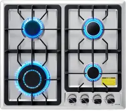
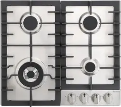
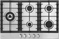
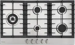
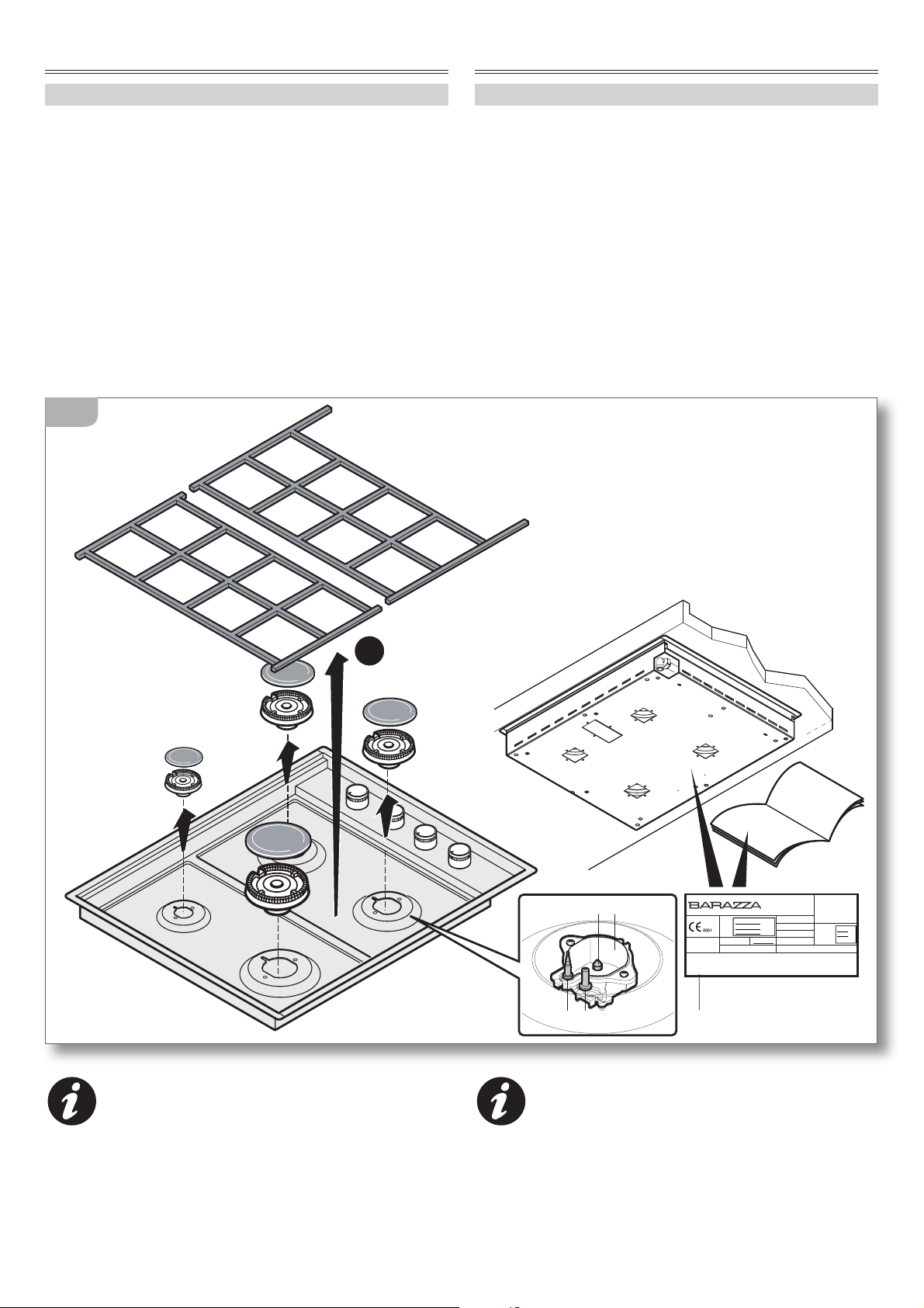
Il presente libretto fornisce indicazioni sul
funzionamento e la manutenzione di diversi
modelli di apparecchiatura; seguire quelle
specifiche per il modello in Vostro possesso.
Esso è facilmente riconoscibile in base all’estetica
della posizione dei bruciatori oppure è rilevabile
dalla targhetta matricola (per il suo posizionamento
vedi
fig. 12).
This booklet provides information about the
operation and maintenance of various appli-
ance models; follow the information specific to
your appliance.
The appliance can be easily recognised based on the ap-
pearance of the burner positions or from the data plate
(for its position see
figure 12).
22
ZONA COMANDI
CONTROL PANEL
65
65
90
90
90
90
40
40
120
120
13A
Per individuare il punto di cottura in rapporto alla
manopola da utilizzare, consultare la serigrafia ripor-
tata vicino alle stesse che identifica in modo chiaro
ed inequivocabile il bruciatore al quale è collegata la
manopola
(fig. 13A - 13B).
In order to determine which knob controls which cook-
ing zone, consult the velvet touch screen which appears
next to the knobs, which clearly and definitively identifies
which knob regulates which burner (figures 13A - 13B).
23
65
65
90
90
40
40
120
120
13B
È BENE SAPERE CHE
Prima di procedere al primo utilizzo, pulite
accuratamente l’apparecchiatura e i suoi
componenti come indicato nel
cap. “Manu-
tenzione ordinaria” di pag. 28
.
Durante i primi utilizzi, l’apparecchiatura potrebbe
emettere fumo e odori sgradevoli: questo è dovuto
alla combustione dei grassi utilizzati per la lavorazione
in fabbrica della stessa, arieggiare i locali.
USEFUL INFORMATION
Before using the appliance for the first time,
carefully clean the appliance including its com-
ponents as specified in the Chapter “
Routine
Maintenance” on page 28
.
During this time the appliance may emit smoke or un-
pleasant odours (due to the burning of the grease used
in the factory processing of the appliance), so the room
should be aired well during its operation.
24
USO DEI BRUCIATORI
Prima dell’utilizzo verificare che gli spar-
tifiamma (2), i bruciatori (3) e le griglie (1) siano
correttamente posizionati.
I bruciatori sono dotati di termocoppia di
sicurezza (8).
La termocoppia è un dispositivo
sensibile al calore: finchè è riscaldata dalla
fiamma del bruciatore acceso permette la fuoriuscita
del gas dall’ugello (9); se la fiamma si spegne per qual-
siasi motivo (es. una fuoriuscita accidentale di liquido
dalla pentola), la termocoppia in pochi secondi si raf-
fredda e questo blocca la fuoriuscita del gas dall’ugello
impedendo che la stanza si saturi di gas incombusto.
Accensione dei bruciatori
1)
(fig. 14) Premere a fondo la manopola corrispon-
dente al bruciatore che si desidera accendere e
contemporaneamente ruotarla fino al simbolo
-> la candela (7) scoccherà le scintille per accen-
dere il bruciatore scelto.
2)
Ad accensione avvenuta tenere ancora premuta a
fondo la manopola per circa 5 secondi mantenen-
dola sempre sul simbolo
poi rilasciarla: questo
tempo serve al riscaldamento della termocoppia di
sicurezza. Se al rilascio della manopola il bruciatore
non rimanesse acceso, significa che la termocoppia
non era ancora sufficientemente calda: ripetere le
operazioni 1) e 2) tenendo premuta più a lungo la
manopola dopo l’accensione del bruciatore.
24
1
3
2
7
8
9
1
2
5”
spento
MAX
MIN
14
USING THE BURNERS
Before using the appliance, check that the
flame distributors (2), the burners (3) and the racks
(1) are correctly positioned.
The burners are equipped with safety thermo-
couples (8).
The thermocouple is a heat-sensitive
device: it is heated by the ignited burner flame,
which permits the thermocouple to control the gas flow
from the nozzle (9); in the case where the flame should go
out for whatever reason, (for example, accidental liquid
spillage from a saucepan), the thermocouple immediately
cools down, blocking the gas flow from the nozzle, subse-
quently preventing unburned gas from filling the room.
Switching on the burners
1)
(figure 14) Press down fully on the knob regulating
the burner you wish to switch on whilst at the same
time rotating it until the symbol
-> appears; the
spark plug (7) will fire sparks in order to switch on the
chosen burner.
2)
Once ignited, keep pressing down fully on the knob
for approximately 5 seconds, still with the symbol
showing, then release the knob: this time period
allows the safety thermocouple to heat up. If upon re-
leasing the knob, the burner does not remain ignited,
this is an indicator that the thermocouple was not
sufficiently heated: repeat stages 1) and 2) keeping
the knob pressed down for longer after the ignition
of the burner.
USO DELL’APPARECCHIATURA USING THE APPLIANCE
25
Regolazione fiamma
3)
Controllare che la fiamma sia regolare e stabile, suc-
cessivamente ruotare la manopola nella posizione
desiderata (MIN
o MAX ).
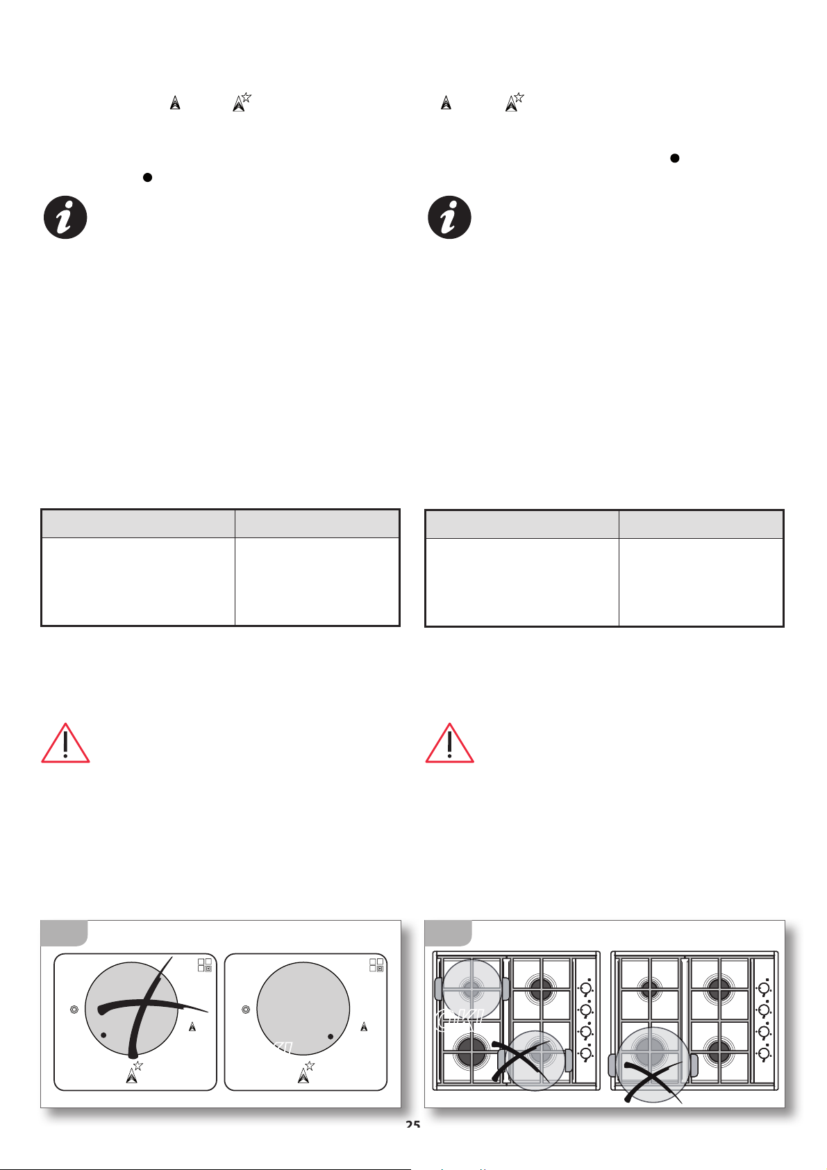
É possibile posizionare la manopola in posizione
intermedia tra la posizione di massimo e quella
di minimo, ma NON tra la posizione di massimo
e quella di “
- spento” (fig. 15).
Se la fiamma risulta irregolare verificare il
corretto posizionamento degli spartifiamma
e dei bruciatori.
Cottura
4)
Posizionate i tegami per la cottura sul bruciatore
acceso: non lasciare gli elementi riscaldanti accesi
senza recipienti o con recipienti vuoti. Per la cottura
utilizzare soltanto pentole, teglie e accessori espressa-
mente concepiti per tale utilizzo, realizzati in materiali
resistenti alle alte temperature e idonei al contatto con
gli alimenti. Per un migliore utilizzo dei bruciatori, è
necessario usare recipienti del diametro adatto al tipo
di bruciatore scelto, in modo da ottenere il massimo
rendimento con il minimo consumo di gas.
Bruciatore ø Recipiente
Ausiliario
Semirapido
Rapido
Tripla corona
da ø 6 a ø 18
da ø 15 a ø 22
da ø 20 a ø 24
da ø 24 a ø 26
Per un maggiore risparmio energetico è consiglia-
bile cuocere con le pentole chiuse dal coperchio
e ridurre la fiamma quanto basta per mantenere
l’ebollizione non appena un liquido inizia a bollire.
Accertarsi che i recipienti di cottura
appoggino correttamente sulla griglia senza
traballare. Le pentole devono essere centrate
rispetto al bruciatore e NON devono sporgere
dalla griglia
(fig. 16). Non è consentito utilizzare
l’apparecchiatura senza la griglia o con diffusori
di calore o riduttori diversi da quelli acquistabili
dal Rivenditore
(fig. 17).
25
OK!
15
Flame control
3)
Check that the flame is steady and stable, subse-
quently rotate the knob to the desired position (MIN
or MAX ).
It is possible to set the knob between the maxi-
mum and minimum settings, but NOT between
the maximum setting and the “
- off” position
(figure 15).
If the flame is irregular, check that the flame
distributors and the burners are correctly posi-
tioned.
Cooking
4)
Place the pan on the lit burner: do not leave burners on
without containers or with empty containers. For cook-
ing, use only containers, pans and accessories that have
been specifically designed for this use, made of high-
temperature-resistant materials and suitable for contact
with foods. For enhanced burner performance, you must
use containers with diameters proportioned to the burner
type chosen, so that you get maximum performance
using the minimum amount of gas.
Burner ø Container
Auxiliary
Semi- rapid
Rapid
Triple ring
from ø 6 to ø 18
from ø 15 to ø 22
from ø 20 to ø 24
from ø 24 to ø 26
For maximum energy saving, we recommend cooking
with the lids on pans/pots and reducing the flame so
that it is simply sufficient enough to maintain boiling
point once a liquid begins to boil.
Ensure that the food containers sit correctly
on the rack without slipping or sliding. Pans/pots
should be centred on the burner and must NOT
protrude the edges of the rack
(figure 16). We do
not recommend using the appliance without the
rack or with heat diffusers or adapters different to
those supplied by the Retailer
(figure 17).
OK!
16
26
Sorvegliare l’apparecchiatura durante
tutto il suo funzionamento.
Durante il funzionamento dell’apparecchia-
tura saranno rilasciati nell’ambiente umidità, calore e
prodotti di combustione. Risulta quindi fondamentale
che il locale sia aerato tramite:
1) aperture naturali (es. finestre, ecc...);
2) aperture artificiali obbligatorie per legge (per le loro
specifiche consultare
pag. 9);
3) cappe di aspirazione/elettroventilatori con condot-
to di scarico e potenza adeguata all’intensità d’uso
dell’apparecchiatura.
Periodicamente verificate che le aperture non siano
state accidentalmente ostruite e il perfetto funziona-
mento dei sistemi di aspirazione.
Pericolo di scottature!
Durante il funzionamento e per alcuni minuti dopo
l’utilizzo, alcune parti dell’apparecchiatura raggiun-
gono temperature molto elevate! Non entrare in
contatto con queste parti senza protezioni personali
adeguate.
Spegnimento dei bruciatori
5)
A cottura ultimata, spegnere l’apparecchiatura
riportando su “
- spento” tutte le manopole.
6)
Togliere le pentole dall’apparecchiatura muniti di
adeguate protezioni personali di sicurezza.
Monitor the appliance during the entire time
it is in operation.
During operation, humidity, heat and combus-
tion emissions will be released into the atmosphere.
Therefore, the area must be well ventilated by way of
the following:
1) natural ventilation (e.g. windows, etc...);
2) man-made ventilation necessitated by law (for details
see
page 9);
3) extractor hoods/electric fans with outlets and suitably
powered in relation to the usage requirements of the
appliance.
Regularly check that the openings are not accidentally
obstructed and that ventilation systems are functioning
perfectly.
Burn hazard!
During operation and for a few minutes after use, some
parts of the appliance reach extremely high tempera-
tures! Do not touch these parts without suitable personal
protection.
Switching off the burners
5)
Once you have finished cooking, switch off the appli-
ance by pressing “
- off” on all the knobs.
6)
Remove the pans/pots from the appliance using suit-
able personal safety equipment.
17
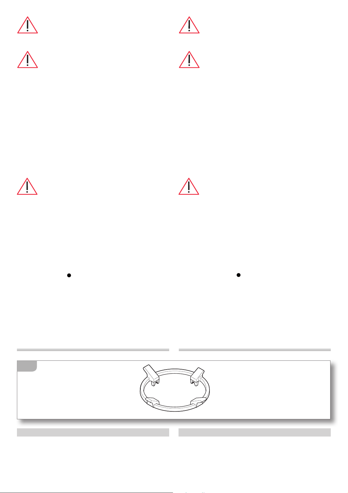
ACCESSORIESACCESSORI
RIDUTTORI
Adattatore in ghisa per pentola WOK.
ADAPTERS
Cast iron WOK adapter.
27
AVVERTENZE DI SICUREZZA
Spegnere sempre l’interruttore elettrico
principale, staccare la spina di collegamento e
chiudere i rubinetti di alimentazione gas prima
di ogni operazione di pulizia o in previsione di
lunga inattività.
Periodicamente controllare che il tubo di
alimentazione gas e il cavo elettrico siano integri e
non schiacciati: nel caso si notasse qualche anoma-
lia non utilizzare l’apparecchiatura e non tentare di
sostituirli da se ma avvisare tempestivamente un
Centro di Assistenza per la loro sostituzione.
Una volta che i componenti dell’apparecchia-
tura si sono raffreddati effettuate la pulizia dopo ogni
uso: ciò rende più agevole l’operazione ed evita che i
residui di cibo possano incendiarsi.
Effettuare la pulizia di TUTTE le parti dell’ap-
parecchiatura solamente con le modalità ed i prodotti
indicati nel presente manuale (in particolare, evitare
nel modo più assoluto spugne abrasive, raschietti,
detergenti acidi o aggressivi, apparecchi a vapore o
a pressione, getti d’acqua diretti).
Una pulizia effettuata in modo diverso da quanto
espressamente descritto potrebbe mettere a rischio la
sicurezza di persone, cose ed animali e causare danni
all’apparecchiatura da non considerarsi in Garanzia.
Pericolo di scottature!
Per alcuni minuti dopo lo spegnimento, alcune parti
dell’apparecchiatura mantengono temperature molto
elevate! Prima di effettuare la pulizia dell’apparecchia-
tura attendere il loro completo raffreddamento.
Se alcune sostanze particolarmente acide (es.
aceto, succo di limone, ecc...) permangono a
lungo sull’apparecchiatura potrebbero intac-
care le superfici creando antiestetici aloni che non
pregiudicano comunque la funzionalità dell’apparec-
chiatura.
SAFETY WARNINGS
Always disconnect the appliance from the
power supply, remove the connection plug from the
socket and shut off gas supply taps before carrying
out any cleaning operations or when the appliance
will not be used for an extended period.
Regularly check that the gas supply pipe and
the electrical cable are in tact and not crushed: if a
fault is noted, do not use the appliance and do not
attempt to replace the parts, instead immediately in-
form the Service Centre and ask for a replacement.
After each use, once the appliance components
have cooled down, clean the appliance: this facilitates
the cleaning operation and prevents the burning of
food residue.
Clean ALL parts of the appliance using only the
procedures and products indicated in this manual (in
particular, do not use abrasive sponges, scrapers, acidic
or aggressive detergents, steam or pressure cleaning
devices, direct water jets).
Any cleaning performed in a manner different from that
specified may endanger the safety of people, animals
and property as well as cause damage to the appliance
which is not covered by the Guarantee.
Burn hazard!
For a few minutes after switching off the appliance,
some parts of the appliance maintain extremely high
temperatures! Before cleaning the appliance, wait until
it has completely cooled down.
If some particularly acidic substances (for exam-
ple, vinegar, lemon juice, etc.) remain for ex-
tended time periods on the appliance, they may
corrode the surface, leaving unsightly marks, which, in
any case, do not affect the operation of the appliance.
MANUTENZIONE MAINTENANCE
28
MANUTENZIONE ORDINARIA
PULIZIA
tSuperfici inox: utilizzare un panno morbido leg-
germente imbevuto di detergente specifico neutro
o aceto caldo: per le modalità d’uso dei prodotti di
pulizia seguire le indicazioni del loro produttore.
tManopole: le manopole non devono essere sfilate
dal perno sul quale sono montate, tale operazione
è riservata all’installatore per la regolazione del
minimo: per la loro pulizia utilizzare un panno
morbido appena imbevuto di detergente neutro
(per le modalità d’uso dei prodotti di pulizia seguire
le indicazioni del loro produttore).
Accertarsi che non ci siano infiltrazioni di
detergente sotto le manopole.
Dopo la pulizia delle manopole accertarsi di
non averle accidentalmente spostate dalla posizio-
ne di “
- spento” .
tSpartifiamma, bruciatori, griglie: dopo che i
componenti si sono raffreddati, rimuoverli dalla
loro sede e lavarli con acqua calda e detersivo per
i piatti.
Lo sporco ostinato sui componenti in ghisa può es-
sere rimosso utilizzando una spugna leggermente
abrasiva ed uno sgrassatore.
Dopo la pulizia, risciacquarli abbondantemente,
asciugarli con molta cura e successivamente rimon-
tarli con la massima attenzione (fig. 18).
Saltuariamente si consiglia di passare le superfici
in ghisa (quando asciutte) con uno straccio legger-
mente imbevuto di olio di oliva.
Non è consentito il loro lavaggio in lavastoviglie.
Lo scolorimento degli elementi in ghisa è un feno-
meno dovuto al normale utilizzo dell’apparecchia-
tura e non ne pregiudica le prestazioni.
Controllare che nessun foro dei bruciatori (3)
sia ostruito da impurità.
Accertarsi che non vi siano impurità all’interno delle
coppe portaugello (6), in tal caso rimuoverle aspiran-
dole senza utilizzare detergenti liquidi o similari.
La brunitura (scurimento) delle griglie in ac-
ciaio (solo per i modelli provvisti) è un feno-
meno dovuto al normale utilizzo dell’apparec-
chiatura e non ne pregiudica le prestazioni.
ROUTINE MAINTENANCE
CLEANING
tStainless steel surfaces: use a soft cloth lightly
dampened in neutral detergent or warm vinegar:
follow the manufacturer’s instructions on the use of
the cleaning products.
tKnobs: the knobs must not be removed from the piv-
ots on which they are attached: this procedure must
be reserved for the person responsible for installation
when setting the idle mode. In order to clean them, use
a soft cloth dampened in neutral detergent (follow the
manufacturer’s instructions on the use of the cleaning
products).
Ensure that the detergent has not remained
lodged under the knobs.
Ensure that upon finishing the cleaning of the
knobs, they have not been accidentally moved from
the “
- off” position.
tFlame distributors, burners, racks: after the com-
ponents have cooled down, remove them from their
housing and wash them with hot water mixed with
washing-up detergent.
The dirt on the cast iron components can be removed
by using a mildly abrasive sponge and a degreaser.
After cleaning, rinse well, carefully dry and subse-
quently, with utmost attention, replace them (figure
18).
We recommend passing a cloth lightly dampened with
olive oil over the cast iron components (once dry).
We do not recommend placing the components in the
dishwasher for cleaning.
Discolouring of cast iron components is normal and
explained by daily wear and tear; it does not affect
their operation.
Check that none of the burner holes (3) are
blocked with impurities.
Ensure that there are no impurities in the double nozzle
holders (6), in such a case, remove them by blowing on
them and without using liquid detergents or similar
products.
Browning (darkening) of stainless steel racks
(only with models supplied) is normal and ex-
plained by daily wear and tear; it does not affect
the operation of the appliance.
29
3
6
2
18
Dopo la pulizia accertarsi di aver rimontato
correttamente le griglie facendo attenzione a non
invertirle. Le griglie inoltre devono risultare stabili e
appoggiare senza traballare sul piano cottura.
PERIODI DI INATTIVITÀ
Se pensate di non utilizzare l’apparecchio per un lungo
periodo di tempo (superiore alle 2-3 settimane):
tFGGFUUVBUFVOBDDVSBUBQVMJ[JBEFMMBQQBSFDDIJBUVSB
seguendo quanto indicato nel capitolo dedicato;
tTDPMMFHBUFMPEBMMBMJNFOUB[JPOFFMFUUSJDBFHBT
PERIODS OF INACTIVITY
If the appliance will not be used for a long period of time
(more than 2-3 weeks):
tUIPSPVHIMZDMFBOUIFBQQMJBODFGPMMPXJOHUIFJOTUSVD-
tions in the respective chapter;
tEJTDPOOFDUJUGSPNUIFQPXFSBOEHBTTVQQMZ
Ensure that upon finishing cleaning, that you have
correctly replaced the racks, taking care not to invert
them. The racks must be stable and must rest on the hob
without slipping or sliding.
30
SMALTIMENTO A FINE VITA
Il prodotto alla fine della propria vita
utile NON deve venire assimilato agli altri
rifiuti ma deve essere smaltito separata-
mente negli idonei centri di raccolta dif-
ferenziata dei rifiuti elettronici ed elettro-
tecnici; lo smaltimento abusivo o non corretto del
prodotto comporta l’applicazione delle sanzioni
previste dalla corrente normativa di legge.
Per maggiori informazioni rivolgersi al servizio
locale di smaltimento rifiuti.
Rendere inutilizzabile l’apparecchiatura per lo
smaltimento rimuovendo il cavo di alimentazione.
ASSISTENZA POST VENDITA
F.lli Barazza Vi assicura la massima collaborazione
nell’eventualità dovessero sorgere problemi tecnici
o qualunque altra necessità.
Procedura in caso di malfunzionamento
Prima di contattare il Centro di Assistenza più comodo
effettuare le seguenti operazioni:
tWFSJGJDBSFDIFDJTJBDPSSFOUFFMFUUSJDB
tSJMFWBSFJEBUJEFMMBQQBSFDDIJBUVSBEBMMBUBSHBNB-
tricola
(posizione targa matricola - vedi pag. 21);
tSFQFSJSFMBEBUBEJBDRVJTUPEFMMBQQBSFDDIJBUVSB
Attenzione! In attesa della risoluzione del
problema è opportuno non utilizzare l’apparecchia-
tura e scollegarla dall’alimentazione elettrica e gas.
Non tentate di riparare o modificare l’apparecchio
in nessuna delle sue parti: oltre a far decadere la Ga-
ranzia, ciò può essere potenzialmente pericoloso.
Richiedere e pretendere che siano utilizzati
unicamente ricambi originali: l’utilizzo di
componentistica diversa da quella fornita dal
Costruttore fa decadere la Garanzia e può arrecare
danni alle persone e all’apparecchiatura stessa.
ENDOFLIFE DISPOSAL
At the end of its service life, the product
must NOT be disposed of together with
other waste but must be disposed of sepa-
rately in the appropriate separate waste
collection centres for electronic and elec-
trotechnical waste; illegal or incorrect disposal of
the product entails the application of sanctions
provided for in current legislation.
For more information, contact your local waste
disposal service.
Before disposing of the appliance, render it unus-
able by removing the power cord.
AFTERSALES SERVICE
Fratelli Barazza ensures you the utmost collaboration in
the event of technical problems or for any other needs
you may have.
Procedure to follow if your appliance is malfunctioning
Before contacting your nearest Service Centre, do the
following:
tDIFDLUIBUUIFBQQMJBODFJTTVQQMJFEXJUIQPXFS
tPCUBJOUIFBQQMJBODFEBUBGSPNUIFEBUBQMBUF
(for
data plate position - see page 21)
;
tGJOEUIFBQQMJBODFQVSDIBTFEBUB
Attention! While waiting for resolution of the
problem, you should stop using the appliance and
disconnect it from the power and gas supply. Do not
attempt to repair or modify the appliance in any of
its parts: in addition to voiding the Guarantee, this
may be dangerous.
Request or demand that only original spare parts
be used: the use of components other than those
supplied by the manufacturer voids the Guaran-
tee and may cause personal injuries or damage the
appliance.


Progetto grafico Artlinea cod. PLAB1 rev. 00 - 05.2010
Fratelli Barazza srl
31025 Sarano di S.Lucia di Piave (TV) ITALIA
Via Risorgimento, 14
Tel. +39 0438 62888
Fax +39 0438 64901
info@barazzasrl.it
www.barazzasrl.it
taste of design