
Installation instructions guide / Instructions d’installation / Instrucciones de instalación
RECIRCULATING KIT (island and wall range hood models)
KIT DE RECYCLAGE (hottes de cuisine de paroi et île)
KIT RECIRCULANTE (para modelos de campana de pared e isla)
READ AND SAVE THESE INSTRUCTIONS
LISEZ ET GARDEZ LES INSTRUCTIONS
LEA Y GUARDE ESTAS INSTRUCCIONES
LI313A
9000979995
2
WARNING
Read and Save These Instructions.
Approved for Residential Appliances only.
PLEASE READ ENTIRE INSTRUCTIONS BEFORE PROCEEDING.
INSTALLER: Please leave these Instructions with this unit for the owner.
OWNER: Please retain these instructions for future reference.
Turn o power circuit at service panel and lock out panel before installing this kit to the appliance.
Installation must comply with all local codes.
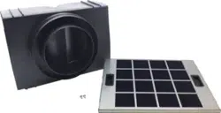
RECIRCULATING KIT model HIREC5UC
(Only for island range hoods)
PACKAGING CONTENTS
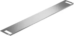
• Airdeector
• Charcoal Filter
• 2 Assembly screws
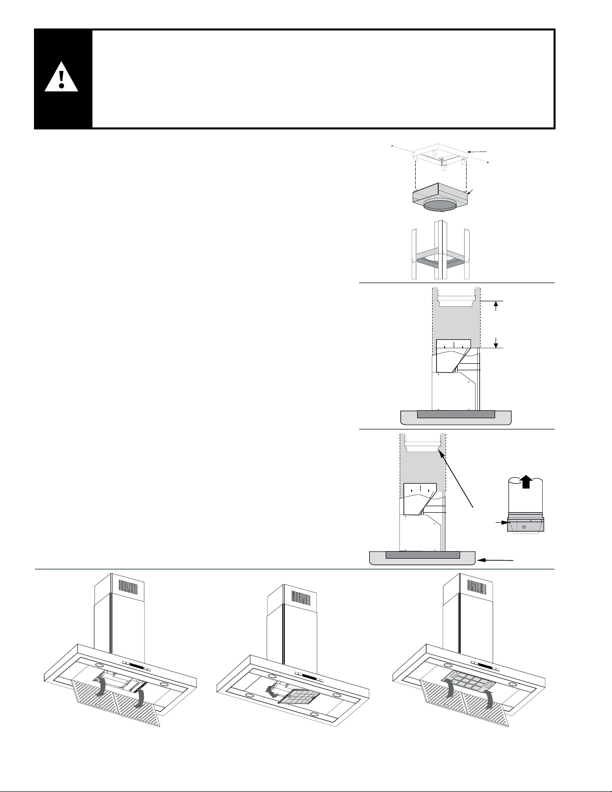
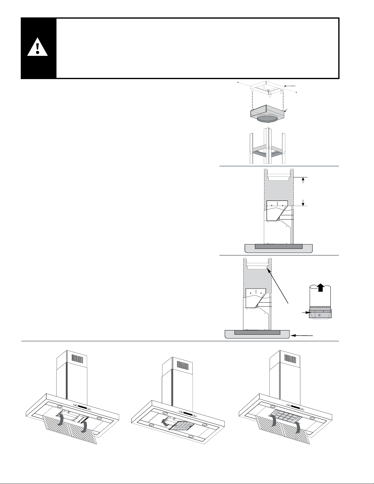
INSTALLATION INSTRUCTIONS
• After the duct cover bracket has been installed on the ceiling
(Refer to Installation Instructions in the Hood Manual), assemble
theairdeectortotheductcoverbracketwith2assemblyscrews,
asisshowning.1.
• Measurefromthebottomoftheairdeectortothebottomofthe
hoodoutlet,asisshowning.2.Cuttheductworkatthe
measured dimension.
• Uninstalltheairdeectorremovingthe2assemblyscrews.
• Sliptheductontothebottomofthedeector.
• Placetheassembleddeectorandductworkovertheexhaust
outlet from the hood.
• Assembletheairdeectortotheductcoverbracket,withthe2
assembly screws provided.
• Useducttapetosealthedeectorandtheexhaustoutletfrom
the hood, as is shown in the following image. The duct tape must
be approved for this application. Fig 3.
CHARCOAL FILTER INSTALLATION
• Removethegreaselterofthehood(a).
• Positionthecharcoallterinsidethestructureofthemotoras
shown in picture b.
• Reinstallthegreaselterontothebottomofthehood(c).
Air
deector
Duct cover
bracket
Dimension
to measure
Airow
Duct tape
over seams
Ductwork
Hood
FIG. 1
FIG. 2
FIG. 3
a) b) c)

3
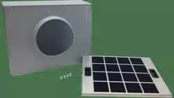
RECIRCULATING KIT model HCREC5UC
(Only for wall range hoods)
PACKAGING CONTENTS
• Airdeector
• Charcoal Filter
• 4 Assembly screws
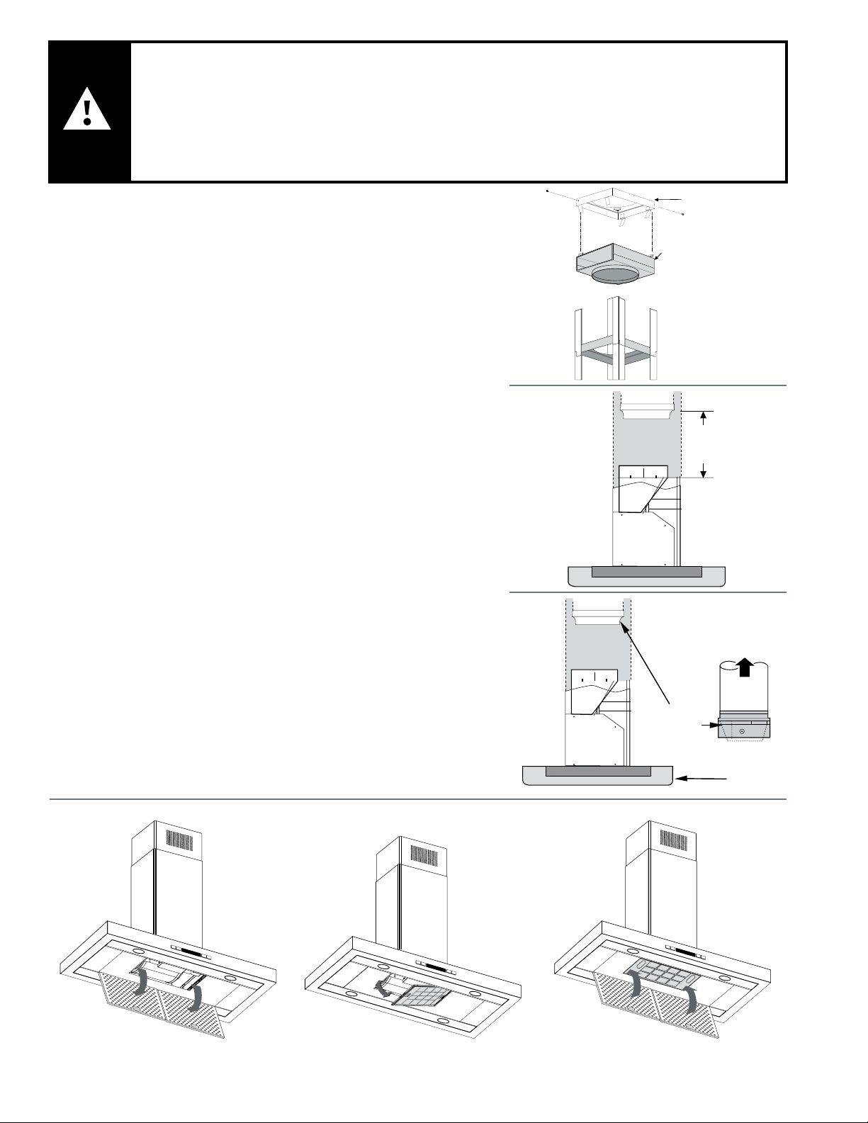
INSTALLATION INSTRUCTIONS
• After the duct cover bracket has been installed on the ceiling
(Refer to Installation Instructions in the Hood Manual), assemble
theairdeectortotheductcoverbracketwith4assemblyscrews,
as is shown in image 1.
• Measurefromthebottomoftheairdeectortothebottomofthe
hood outlet, as is shown in image 2. Cut the ductwork at the
measured dimension.
• Uninstalltheairdeectorremovingthe4assemblyscrews.
• Sliptheductontothebottomofthedeector.
• Placetheassembleddeectorandductworkovertheexhaust
outlet from the hood.
• Assembletheairdeectortotheductcoverbracket,withthe4
assembly screws provided.
• Useducttapetosealthedeectorandtheexhaustoutletfrom
the hood, as is shown in the following image. The duct tape must
be approved for this application. Image 3.
CHARCOAL FILTER INSTALLATION
• Removethegreaselterofthehood(a).
• Positionthecharcoallterinsidethestructureofthemotoras
shown in picture b.
• Reinstallthegreaselterontothebottomofthehood(c).
Air
deector
Mounting
screws
Duct cover
bracket
Air
deector
Dimension
to measure
Airow
Duct tape
over seams
Ductwork
Hood
a)
b)
c)
FIG. 1
FIG. 2
FIG. 3
4
ATTENTION:
Lisez et gardez les instryctions
Approuvé pour applications residentiels.
S’IL VOUS PLAÎT, LISEZ COMPLET LES INSTRUCTIONS AVANT THE COMMENCER.
PERSON QUI VA INSTALLER: S’il vous plaît, lassez les instructions chez le propriétaire.
PROPRIÈTAIRE: S’il vous plaît gardez les instructions, pour doutes futurews.
Èteindrez I’ énergie circuit dans le panel de services et fermez le panel avant d’installer ce kit
pour I’utilisation. L’installation doit été complété avec les louces de la région.
RECIRCULATION KIT modèle HIREC5UC
(Seulement pour les hottes de cuisine île)
CONTENU D’EMBALLAGE
• Déecteurd´air
• Filtre de charbon de bois
• 2 vis d’assemblée
INSTRUCTIONS D’ INSTALLATION
• Après que l’étagère de couverture de conduit a été installée sur le
toit (plafond). (Il fait référence de le manuel de l‘hotte sur les
instructionsd’installation),assemblezledéecteurd’airál’étagère
de couverture de conduit avec le 2 vis d’assemblée, comment
danslagure1.
• Mesurezdel’inférieurdudéecteurdel’airàl’inférieurdel’hotte
aspirante,comments’estmontréedanslagure2.Coupezle
conduit de travail dans la dimension mesurée.
• Pour désinstallé le déecteur d’air il faut enlever les 2 vis
d’assemblée.
• Glissezleconduitsurlefonddudéecteur.
• Placezleassemblédéecteuretleconduitdetravailau-dessusde
l’oriced’échappementdel’hotteaspirante.
• Assemblezledéecteurd’airàl’étagèredecouverturedeconduit,
avec les 2 vis d’assemblée fournies.
• Utilisezleconduitadhésifpourscellerledéecteuretl’orice
d’échappement de l’hotte aspirante, comme est montré dans
l’image suivante. Le conduit adhésif doit être approuvée pour cette
application. Fig. 3.
INSTALLATION DU FILTRE DE CHARBON DE BOIS
• Enlevezleltredegraissel’hotteaspirante(a).
• Placezleltredecharbondeboisàl’intérieurdelastructuredu
moteur comme est montré dans l’image b.
• Réinstallezleltredegraissesurlefonddel’hotteaspirante(c).
Déecteur
d’air
L’étagère de
couverture de
conduit
Dimension
mesurée.
Circulation
d’air
Conduit
de travail
Canalisation
Hotte de
la cuisiniere
FIG. 1
FIG. 2
FIG. 3
a) b) c)
5
KIT DE RECYCLAGE modèle HCREC5UC
(Seulement pour les hottes de cuisine de paroi)
CONTENU D’EMBALLAGE
• Déecteurd´air
• Filtre de charbon de bois
• 4 vis d’assemblée
INSTRUCTIONS D’ INSTALLATION
• Après que l’étagère de couverture de conduit a été installée sur le
toit (plafond). (Il fait référence de le manuel de l‘hotte sur les
instructionsd’installation),assemblezledéecteurd’airál’étagère
de couverture de conduit avec le 4 vis d’assemblée, comment
danslagure1.
• Mesurezdel’inférieurdudéecteurdel’airàl’inférieurdel’hotte
aspirante,comments’estmontréedanslagure2.Coupezle
conduit de travail dans la dimension mesurée.
• Pour désinstallé le déecteur d’air il faut enlever les 4 vis
d’assemblée.
• Glissezleconduitsurlefonddudéecteur.
• Placezleassemblédéecteuretleconduitdetravailau-dessusde
l’oriced’échappementdel’hotteaspirante.
• Assemblezledéecteurd’airàl’étagèredecouverturedeconduit,
avec les 4 vis d’assemblée fournies.
• Utilisezleconduitadhésifpourscellerledéecteuretl’orice
d’échappement de l’hotte aspirante, comme est montré dans
l’image suivante. Le conduit adhésif doit être approuvée pour cette
application. Fig. 3.
INSTALLATION DU FILTRE DE CHARBON DE BOIS
• Enlevezleltredegraissel’hotteaspirante(a).
• Placezleltredecharbondeboisàl’intérieurdelastructuredu
moteur comme est montré dans l’image b.
• Réinstallezleltredegraissesurlefonddel’hotteaspirante(c).
Air
deector
Mounting
screws
Duct cover
bracket
Air
deector
Dimension
to measure
Airow
Duct tape
over seams
Ductwork
Hood
a)
b)
c)
FIG. 1
FIG. 2
FIG. 3
6
FIG. 1
FIG. 2
FIG. 3
a) b) c)
PRECAUCIÓN:
Lea y guarde estas instrucciones.
Aprobado para electrodoméstico residencial únicamente.
POR FAVOR LEA COMPLETAMENTE ESTAS INSTRUCCIONES ANTES DE PROCEDER.
INSTALADOR: Por favor deje estas instrucciones al propietario.
PROPIETARIO: Por favor mantenga estas instrucciones para futuras referencias.
Desconecte esta unidad del tablero de control eléctrico y asegure el panel de control antes de instalar
este accesorio a la campana. La instalación debe cumplir con todos los estatutos locales.
KIT RECIRCULANTE modelo HIREC5UC
(Sólo para campanas de Isla)
CONTENIDO EN EMPAQUE
• Deectordeaire
• Filtro de carbón
• 2 Tornillos de ensamble
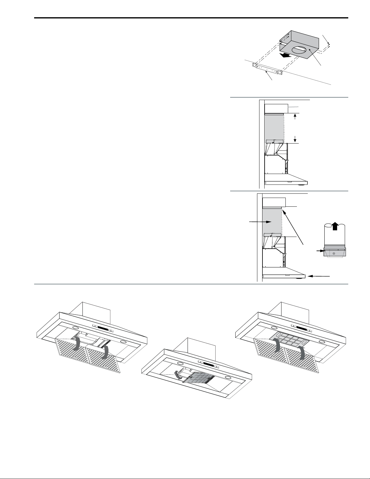
INSTRUCCIONES PARA INSTALACIÓN
• Después de que el soporte para cubre ductos ha 1 sido instalado
en el techo (Haga referencia al manual de instalación de la
campana).ensambleeldectordeaireenelsoportedecubre
ductos con 2 tornillos de ensamble, tal y como se muestra en la
gura1.
• Midadesdelaparteinferiordeldeectordeairealaparteinferior
del escape en la campana. Corte el ducto a la dimensión medida,
comosemuestraenlagura2.
• Desinstaleeldeectordeaireremoviendolos2tornillosde
ensamble.
• Desliceelductoenlaparteinferiordeldeector.
• Posicioneelensambledeldeectordeaireyductosobreel
escape de aire en la campana.
• Ensambleeldeectordeaireenelsoportedecubreductos
utilizando los 2 tornillos de ensamble.
• Utilicecintaespecialparasellarlasunionesdelductoaldeector
yalescapedelacampanacomosemuestraenlasiguientegura,
La cinta para sellar el ducto debe estar aprobada para la
aplicación. Fig. 3
INSTALACIÓN DEL FILTRO DE CARBÓN
• Remuevaelltrodegrasadelacampana(a).
• Posicioneelltrodecarbóndentrodelaestructuradelmotor
comosemuestraenlagurab.
• Reinstaleelltrodegrasaenlacampana(c).
Deector
de aire
Soporte para
cubreductos
Dimension
a medir
Flujo de aire
Cinta especial
para sellar
Ducto
Csmpsns

7
KIT RECIRCULANTE modelO HCREC5UC
(Sólo para campanas de pared)
CONTENIDO EN EMPAQUE
• Deectordeaire
• Filtro de carbón
• 4 Tornillos de ensamble
INSTRUCCIONES PARA INSTALACIÓN
• Después de que el soporte para cubre ductos ha sido instalado
en el techo (Haga referencia al manual de instalación de la
campana).ensambleeldeectordeaireenelsoportedecubre
ductos con 4 tornillos de ensamble, tal y como se muestra en la
gura1.
• Midadesdelaparteinferiordeldeectordeairealaparteinferior
del escape en la campana. Corte el ducto a la dimensión medida,
comosemuestraenlagura2.
• Desinstaleeldeectordeaireremoviendolos4tornillosde
ensamble.
• Desliceelductoenlaparteinferiordeldeector.
• Posicioneelensambledeldeectordeaireyductosobreel
escape de aire en la campana.
• Ensambleeldeectordeaireenelsoportedecubreductos
utilizando los 4 tornillos de ensamble.
• Utilicecintaespecialparasellarlasunionesdelductoaldeector
yalescapedelacampanacomosemuestraenlasiguientegura,
La cinta para sellar el ducto debe estar aprobada para la
aplicación. Fig. 3
INSTALACIÓN DEL FILTRO DE CARBÓN
• Remuevaelltrodegrasadelacampana(a).
• Posicioneelltrodecarbóndentrodelaestructuradelmotor
comosemuestraenlagurab.
• Reinstaleelltrodegrasaenlacampana(c).
Air
deector
Mounting
screws
Duct cover
bracket
Air
deector
Dimension
to measure
Airow
Duct tape
over seams
Ductwork
Hood
a)
b)
c)
FIG. 1
FIG. 2
FIG. 3