Loading ...
Loading ...
Loading ...
10
6. Push microwave oven against mounting plate
and hold in place.
NOTE: If microwave oven does not need to be adjusted,
skip steps 7-9.
7. If adjustment is required, rotate microwave oven downward.
Using 2 or more people, lift microwave oven off of mounting
plate, and set aside on a covered surface.
8. Loosen mounting plate screws. Adjust mounting plate
and retighten screws.
9. Repeat steps 3-6.
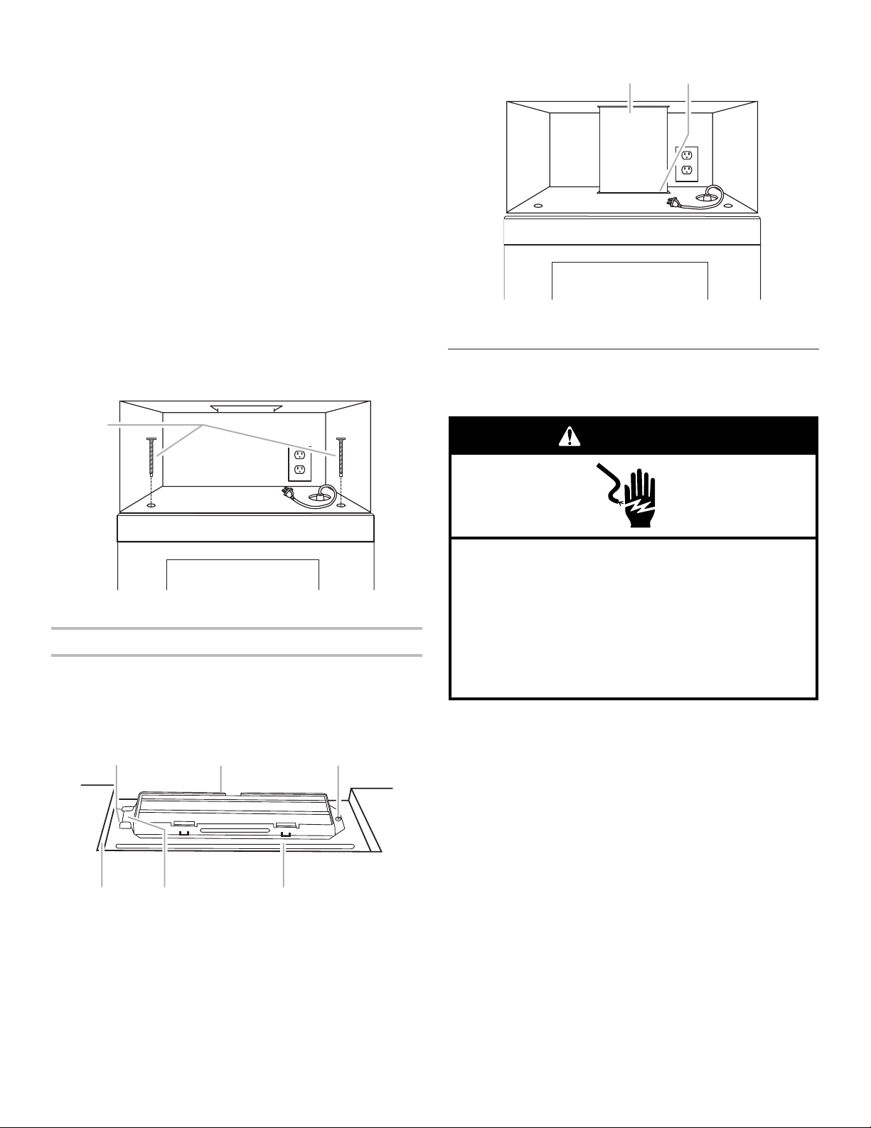
10. With the microwave oven centered, and with at least one
person holding it in place, insert bolts through upper cabinet
into microwave oven. Tighten bolts until there is no gap
between upper cabinet and microwave oven.
NOTES:
■ Some upper cabinets may require bolts longer or shorter
than 3" (7.6 cm). Longer or shorter bolts are available
at most hardware stores.
■ Overtightening bolts may warp the top of the microwave
oven. To avoid warping, wood filler blocks (installer to
provide) may be added. The blocks must be the same
thickness as the space between the upper cabinet
bottom and the microwave oven.
For Roof Venting Installation Only
1. Insert damper assembly through the cabinet cutout so
that the long tab of the damper assembly slides under
the raised tabs of the damper plate. Then secure with
sheet metal screw.
NOTE: The screw cannot be installed if the damper assembly
is not positioned as shown.
2. Connect vent to damper assembly.
Complete Installation
1. Install filters. Refer to the User Instructions for
filter placement.
2. Plug microwave oven into grounded 3 prong outlet.
3. Reconnect power.
4. Check the operation of microwave oven by placing 1 cup
(250 mL) of water on the turntable and programming
a cook time of 1 minute at 100% power. Test vent fan
and exhaust by operating the vent fan.
5. If the microwave oven does not operate:
■ Check that a household fuse has not blown or that
a circuit breaker has not tripped. Replace the fuse
or reset the circuit breaker. If the problem continues,
call an electrician.
■ Check that the power supply cord is plugged
into a grounded 3 prong outlet.
■ See the User Instructions for troubleshooting information.
Installation is now complete.
Save Installation Instructions for future use.
A
A. Bolts
A B C
D E F
A. Raised tabs
B. Damper assembly
C. Sheet metal screw
D. Upper cabinet cutout
E. Long tab
F. Damper plate
A B
A. Vent
B. Damper assembly (under vent)
Electrical Shock Hazard
Plug into a grounded 3 prong outlet.
Do not remove ground prong.
Do not use an adapter.
Do not use an extension cord.
Failure to follow these instructions can result in death,
fire, or electrical shock.
WARNING
Loading ...
Loading ...