Loading ...
Loading ...
Loading ...
21
English
3
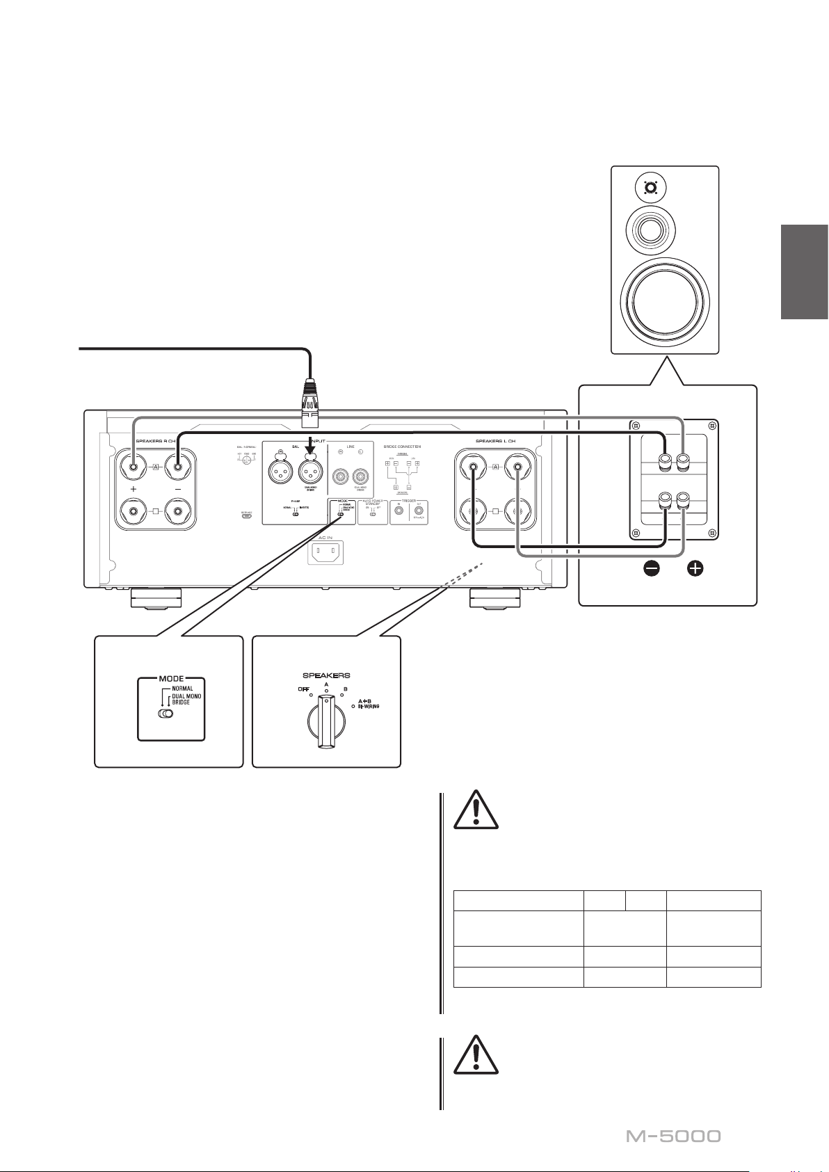
Set the MODE selector on the rear panel to
DUAL MONO/BRIDGE.
4
Set the SPEAKERS selector on the front
panel to A, B, or A+B BI-WIRING.
The diagram shows the selector set to A.
5
Connect the power amplier (this unit) to
the speakers.
For each channel speaker, connect the cables
from the speaker’s mid/high range terminals to
the amplier A jacks for the SPEAKERS R CH,
and from the speaker’s low range terminals to the
amplier A jacks for the SPEAKERS L CH.
CAUTION
Be sure to use speakers that feature the impedance shown
in the table below.
Speaker impedance
SPEAKERS selector A B A+B
Basic connection/
Bi-wiring connection
4Ω or higher 8Ω or higher
Bi-amp connection 4Ω or higher 8Ω or higher
Bridge connection 8Ω or higher 16Ω or higher*
* Excluding models for U.S.A. and Canada
CAUTION
Before turning the power back on to the source component,
rst lower the volume level on that component.
B
B
B
B
SPEAKERS
OFF
A
B
A
+
B
WIRING
BI
High
Low
High
Low
M-5000
M-5000
MODE: DUAL MONO/BRIDGE
SPEAKERS
OFF
A
B
A
+
B
WIRING
BI
MODE: DUAL MONO/BRIDGE
Remove the shorting bar.
L channel
MODE selector
L channel
SPEAKERS selector
(front panel)
Loading ...
Loading ...
Loading ...