Loading ...
Loading ...
Loading ...
14
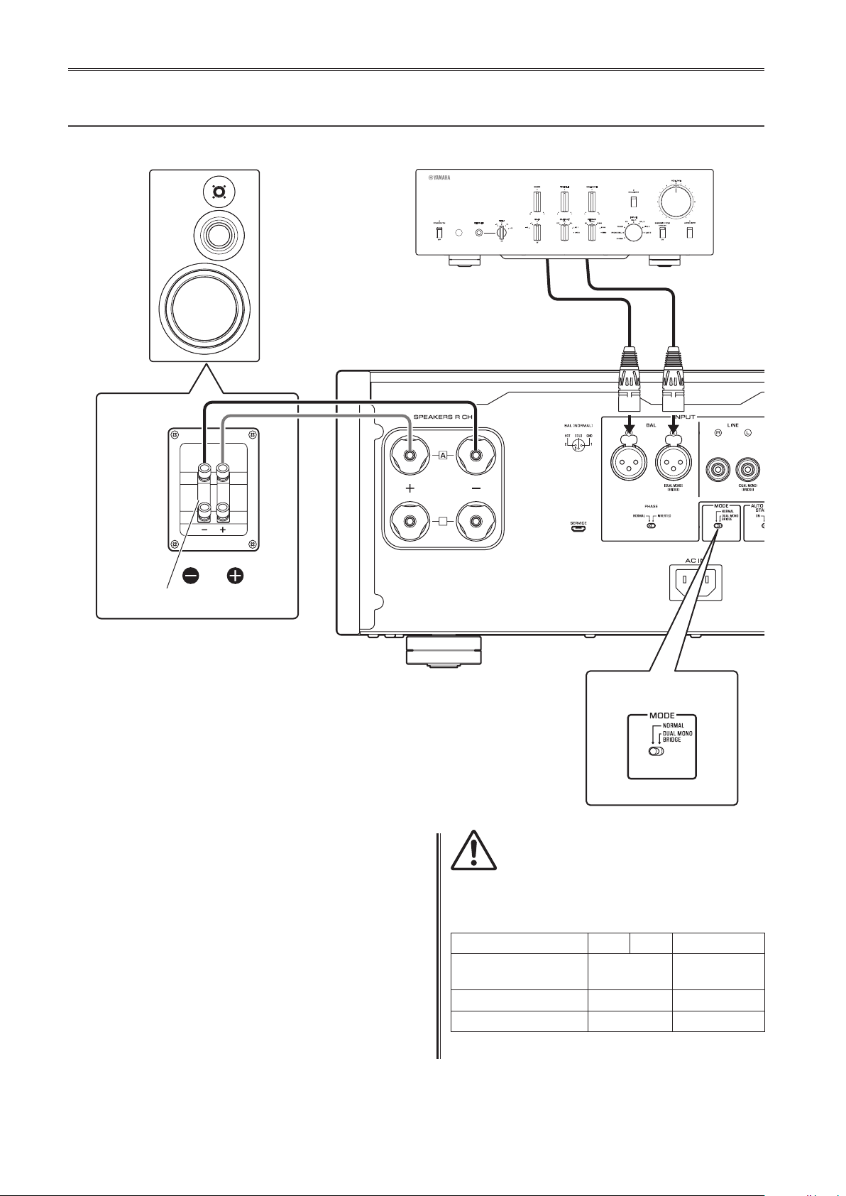
Basic speaker connections
1
Turn o the power to the unit and all
connected components.
2
Set the MODE selector on the rear panel to
NORMAL.
3
Set the SPEAKERS selector on the front
panel to A, B, or A+B BI-WIRING.
The diagram shows the selector set to A.
4
Connect the power amplier to the “+” and
“−” terminals of the speakers.
CAUTION
Be sure to use speakers that feature the impedance shown
in the table below.
Speaker impedance
SPEAKERS selector A B A+B
Basic connection/
Bi-wiring connection
4Ω or higher 8Ω or higher
Bi-amp connection 4Ω or higher 8Ω or higher
Bridge connection 8Ω or higher 16Ω or higher*
* Excluding models for U.S.A. and Canada
B
B
SPEAKERS
OFF
A
B
A
+
B
WIRING
BI
High
Low
High
Low
MODE: NORMAL
M-5000
MODE selector
Shorting bar
Preamplier
R channel
R channel L channel
R channel signal L channel signal
R channel
Loading ...
Loading ...
Loading ...