Loading ...
Loading ...
Loading ...
Version 10/12 - Page 11
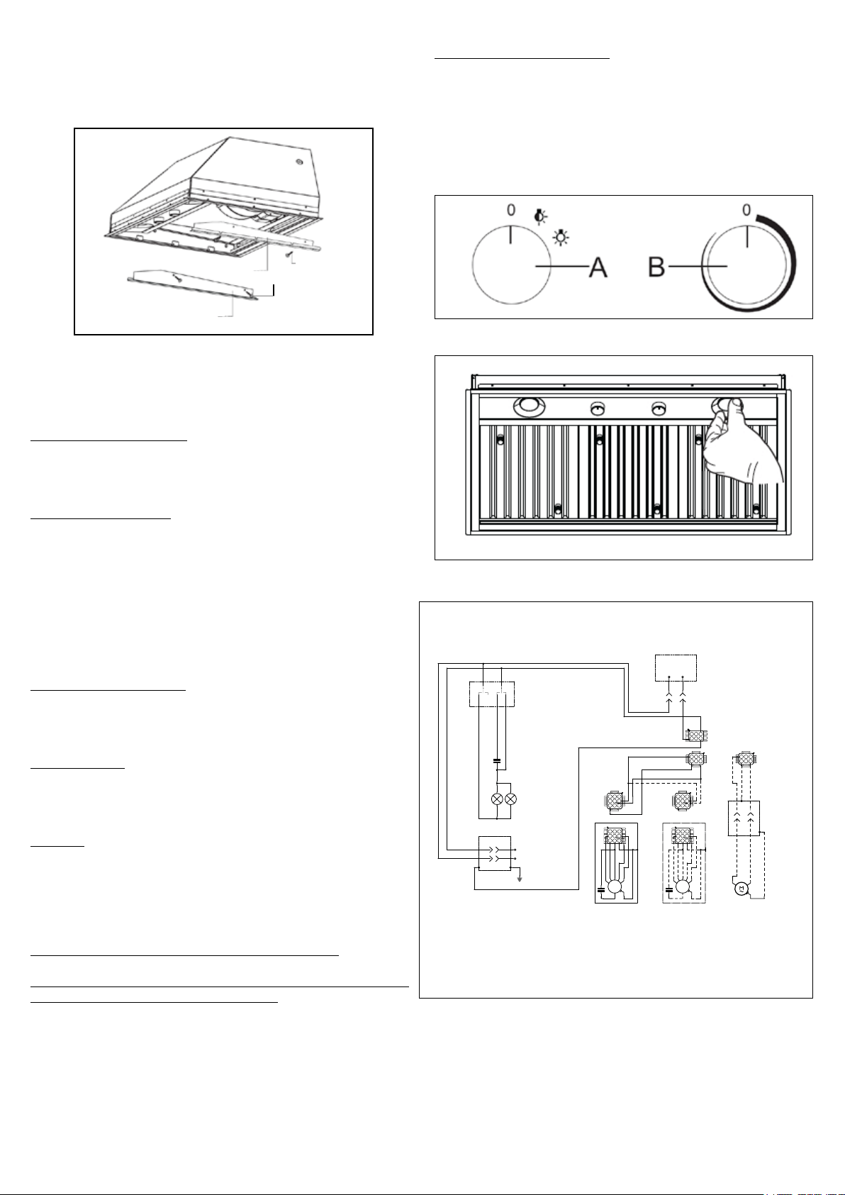
Light On/Off Button (A)
On/Offswitchforthehalogenlights.Position"0"turnsthelightsoff,
turningtheswitchtotherightoneclickisthedimmerposition,and
thenextclicktotherightisfullpower
Blower On/Off Button (B)
On/Offswitchfortheblower.Movethedialtotherighttoturnthe
blowerONandvarythespeedoftheblower.Turntotheleftat"0"
to turn it OFF.
For Best Result
Starttherangehoodseveralminutesbeforecookingtodevelopproper
airow.Allowtheunittooperateforseveralminutesaftercookingis
complete to clear all smoke and odors from the kitchen.
Cleaning
Thestainlesssteelgreaseltersandgreaserailshouldbecleaned
frequentlyin hotdetergentsolution orwashedin thedishwasher.
Cleanexteriorsurfaceswithacommerciallyavailablestainlesssteel
cleaner. Abrasives and scouring agents can scratch stainless steel
nishesandshouldnotbeusedtocleannishedsurfaces.
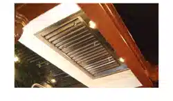
Grease rail and Grease Filter Installation / Removal
Remove the plastic from the lter, the knobs need to be installed
onto the lter with 2 screws to each lter
Installthegreaserailintothebackofthehood,intotheslotsonthe
insideooroftherearofthehood.TheGreaseltersshouldbe
installedbeforeoperatingtherangehood.Toinstallthelters,usethe
twoknobs(inFIGURE28)toholdthelterandinsertthelterinto
the front edge of the hood with the knobs facing out into the spring
loadedslot.Installtheotherendofthelterabovethegreaserailin
the back of the hood.
USE AND CARE INFORMATION
Thisrangehoodsystemisdesignedtoremovesmoke,cookingvapors
and odors from the cooktop area.
Rangehood Control Panel
Thecontrolpanelislocatedinthecenterofthehoodbottom.The
position and function of each control button are indicated in FIGURE
27
FIGURE 28
Replacing the Halogen Lamp
Beforeyoubegin,makesurethattherangehoodisturnedoffand
thattheotherlampshavehadsufcienttimetocool.Halogenlamps
burnextremelyhotandseriousinjurycouldresultfromtouchingahot
lamp.Pressandtwistthelamptoremove.Thenremovethelamp
and replace with a new lamp.
WIRING DIAGRAM
This rangehood uses 45 watt PAR16
Halogen Lamps.
FIGURE 27
FIGURE 26
ALL INSTALLATIONS
1. Use a drill to install side rails on the inside rangehood walls to
linetheinsidehoodwallwithstainless,2and3inFIGURE26with
9a.screws,4screwstotal.
0 1 2 3 4 5 6 7 8 9
Creato da.
Rev :
Ver :
DOLCE CORRADO
3
Materiali: non deveno contenere Pb, Cr6+, Hg, PBB, pbde, ai sensi della direttiva 2002/95 CE
SCHEMA ELETTRICO INCA PRO PLUS UL
Disposizione di messa a terra
Non rilevare quote dal grafico non apportare mod ifiche senza l'autorizzazione d'ufficio progettazione
a termini di legge ci riserviamo la proprieta' del pr esente disegno con divieto di riproduzione totale o parziale
Code :
Disegno N :
Data:
11.Nov.2010
436005092
H90_059
BLK
WHT
R11B41
LIGHT CONTROL
OFF / HALF LIGHT / ON
1
Y-G
A
RED
WIRING BOX
WHT
BLK
BLK
2 3
B
ORG
WHT
4
VLT
N
L
Y-G
LINE IN
120Vac
60Hz ~
Y-G
BLU
123
6 5 4
789
1 2 3
654
987
RED
M8 4V
120V ~
WHT
BRW
BLU
BLK
ORG
BLU
BLK
Y-G
Y-G
ON/OFF MOTOR
SPEED CONTROL
BLKBLK
BLU
123
6 5 4
789
1 2 3
654
987
RED
M8 4V
120V ~
BLU
Y-G
WHT
BRW
BLKBLK
BLU
1 2 3
654
123
6 5 4
BLK
ORG
Y-G
BLU
WHT
BLK
Y-G
WIRING BOX FOR
REMOTE BLOWER
WHT
REMOTE
BLOWER
123
6 5 4
WHT
Y-G
BLKBLK
Y-G
9a
2
3
9a
9a
Loading ...
Loading ...
Loading ...