Loading ...
Loading ...
Loading ...
19
Nettoyagedesltresàgraissemétal-
liques
Les ltres à graisse métalliques peuvent être
lavés dans une solution d'eau chaude savon-
neuse ou dans le lave-vaisselle. Ils devraient
être nettoyés tous les 2 mois d'utilisation, ou
plus fréquemment en cas d'utilisation particu-
lièrement intensive.
• Retirez le ltre, en poussant simultanément
le levier vers l'arrière de l'appareil et en le
tirant vers le bas.
• Lavez le ltre sans le plier. Laissez-le sécher
complètement avant de le réinstaller (un
changement de la couleur à la surface du
ltre au l du temps n'a aucun impact sur
son efcacité).
• Remettez-le en place, en vous assurant que
la poignée se trouve vers l'avant.
• Le lave-vaisselle pourrait ternir le ni du ltre
à graisse métallique.
Remplacementdultreàcharbon
actif
Les ltres à charbon actif ne sont pas
lavables et ne peuvent être régénérés. Ils
doivent être remplacés environ tous les 4
mois d'utilisation, ou plus souvent en cas
d'utilisation intensive.
• Retirez les ltres à graisse.
• Retirez le ltre à charbon saturé.
• Posez le nouveau ltre en l'installant à son
emplacement.
• Replacez les ltres à graisse.
Remplacement des ampoules
Halogène 28 W avec culot E14.
• Retirez les ltres à graisse métalliques.
• Remplacez l'ampoule avec une nouvelle du
même type.
• Replacez les ltres à graisse métalliques.
EN
7
7
INSTALLATION
Fitting the Hood canopy
BEFORE FITTING THE HOOD TO THE WALL UNIT, PROCEED AS FOLLOWS:
• Disconnect the wires to the Commands at the connectors.
• Disconnect the wires to the Light at the con-
nectors.
• The Hood can be installed directly on the
underside of
the wall unit (Minimum 650 mm
from the Cooker Hob).
• Create an opening in the bottom of the wall unit,
as shown.
• Insert the hood until the side supports snap into
place.
• Fasten using the 10 screws 12a provided.
• Lock in position by tightening the screws Vf from
underneath the hood.
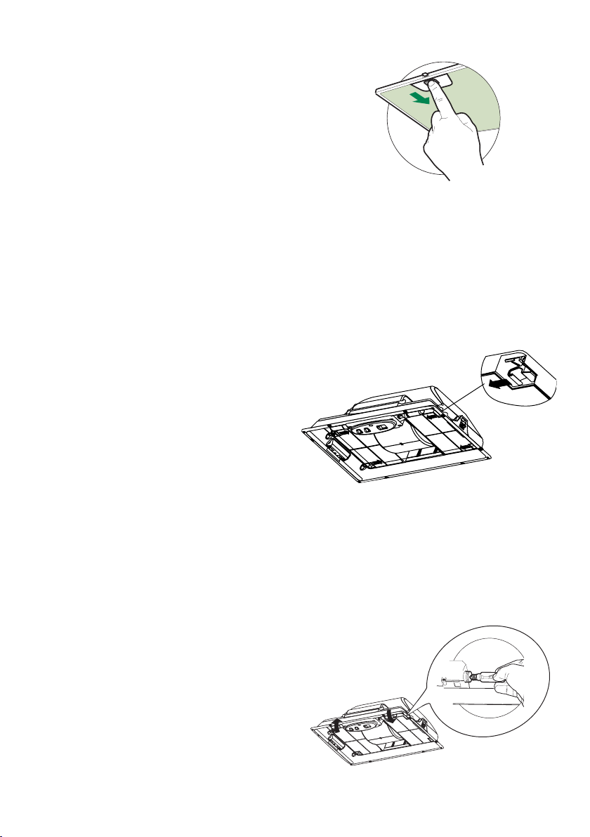
• Open the suction panel by turning the specific knob.
• Disconnect the panel from the hood canopy by sliding the
fixing pin lever.
• Remove grease filters.
• Screw the Frame into place
using the 6 scr
ews 12f, re-
connect the wires to the
Commands and Light, re-
place the metal grease filter
and the Panel.
260
13
495 - 675
Version 09/14 - Page 6
RECIRCULATING INSTALLATIONS
For recirculating installations (FIGURE 1), Charcoal Filters are necessary. The
(A in FIGURE
1). Recirculating installations also require some duct work to divert the air out of the
cabinet. The duct work must not terminate inside the cabinet.
MAKE YOUR CUT-OUTS
1. Disconnect and move freestanding range from cabinet opening to provide easier
access to upper cabinet and rear wall. Put a thick, protective covering over cooktop,
set-in range or countertop to protect from damage or dirt.
2. Determine and clearly mark with a pencil the center li
ne on the cabinet where
the rangehood will be installed.
3. Determine and make all necessary cuts in the wall for the ductwork. Install the
ductwork before the rangehood.
4. Determine the proper location for the Power Supply Cable. Use a 1
1/4"
Drill Bit
to make this hole. Install the cable. Use caulking to seal around the hole. DO NOT
turn on the power until installation is complete.
5. Make the cut-out opening where the rangehood will be installe
d (FIGURE 2).
26 21/32" WIDTH FOR 28" HOOD, 19 19/32" WIDTH FOR 24" HOOD
INSTALL THE RANGEHOOD
1.
-
face to prevent accidental damage. Remove all parts including the backdraft damper,
g the carton.
2. Place the round damper into the exhaust opening of the rangehood and press
down.
3. Remove the bottom of the rangehood by pulling on the grey tabs (A in FIGURE
3) located on either side.
4. Fix the rangehood to the cabinet using the two spring loaded brackets, one on
each side of the rangehood (B in FIGURE 4) . Using a philips screwdriver, tighten
the adjustment screw (C in FIGURE 4) until the brackets adhere tightly to the surface.
For thicknesse
s of LESS than
3/4",
the cabinet bottom and the spring loaded bracket.
5. IMPORTANT:
(FIGURE 4) .
6. Replace the bottom of the rangehood and secure by pushing in the grey tabs (A
in FIGURE 3) .
7.
Feed the Power Supply Cable through the electrical knockout. Connect the Power
Supply Cable to the rangehood cable. Attach the White lead of the power supply
to the White lead of the rangehood with a twist-on type wire connector. Attach the
Black lead of the power supply to the Black lead of the rangehood with a twist-on
type wire connector. Attach the Power Supply Cable grounding lead to the green screw
.)dedivorp ton swercs( noitacol elbaC ylppuS rewoP ruoy yb detatcid sa tenibac ro
Replace the cover.
8. Connect the ductwork to the damper and seal all connections with duct tape.
9. Turn the power supply on. Turn on the blower and light. If the rangehood does
not operate, check that the circuit breaker is not tripped or the house fuse blown. If
the unit still does not operate, disconnect the power supply and check that the wiring
connection
s have been made properly.
FIGURE 1
FIGURE 2
FIGURE 4
FIGURE 3
FIGURE 7
A
5” round
duct
cabinet
ceiling
inca smart
cabinet
ceiling
5” round
duct
inca smart
A
Install a grille or louver vent at the air outlet.
Cabinet min
H=30”
Loading ...
Loading ...
Loading ...