Loading ...
Loading ...
Loading ...
12
/ Installation requirements / Electrical connection
ELECTRICAL
A properly-grounded horizontally- mounted electri-
cal receptacle should be installed.
Check all local code requirements.
GAS
An agency-approved, properly-sized manual shut-
off valve should be installed.
To connect gas between shut-off valve and regula-
tor, use agency-approved, properly sized fl exible
or rigid pipe. Check all local code requirements.
Warning!
ELECTRICAL SHOCK HAZARD
Disconnect electrical power at the circuit bre-
aker box or fuse box before installing the ap-
pliance.
Provide appropriate ground for the appliance.
Use copper conductors only.
Failure to follow these instructions could re-
sult in serious injury or death.
This unit is manufactured for a polarized, groun-
ded 120 volt/60 Hz, 16 amp system.
Electric power consumption is about 200 W for
36”, 1200W for 48”
The minimum of 102 VAC is required for proper
operation of gas ignition systems.
The circuit must be grounded and properly pola-
rized.
The unit is equipped with a SJT power cord and
a NEMA 5-15P plug. In case of replacement, the
power cord shall be replaced with one of the same
type, size and length.
Warning!
Electrical grounding
This appliance is equipped with a three-prong
plug for your protection against shock hazard and
should be plugged directly into a properly groun-
ded socket. Do not cut or remove the grounding
prong from this plug.
Caution
Label all wires prior to disconnecting when
servicing controls. Wiring errors can cause
improper and dangerous operation.
Verify proper operation after servicing.
For appliances equipped with a cord and plug,
do not cut or remove the ground prong. It must
be plugged into a matching grounding type re-
ceptacle to avoid electrical shock. If there is any
doubt as to whether the wall receptacle is properly
grounded, the customer should have it checked
by a certifi ed electrician.
Do not use an extension cord with the gas co-
oktop.
Plan the installation so that the power connection
is accessible from the front of the cabinet.
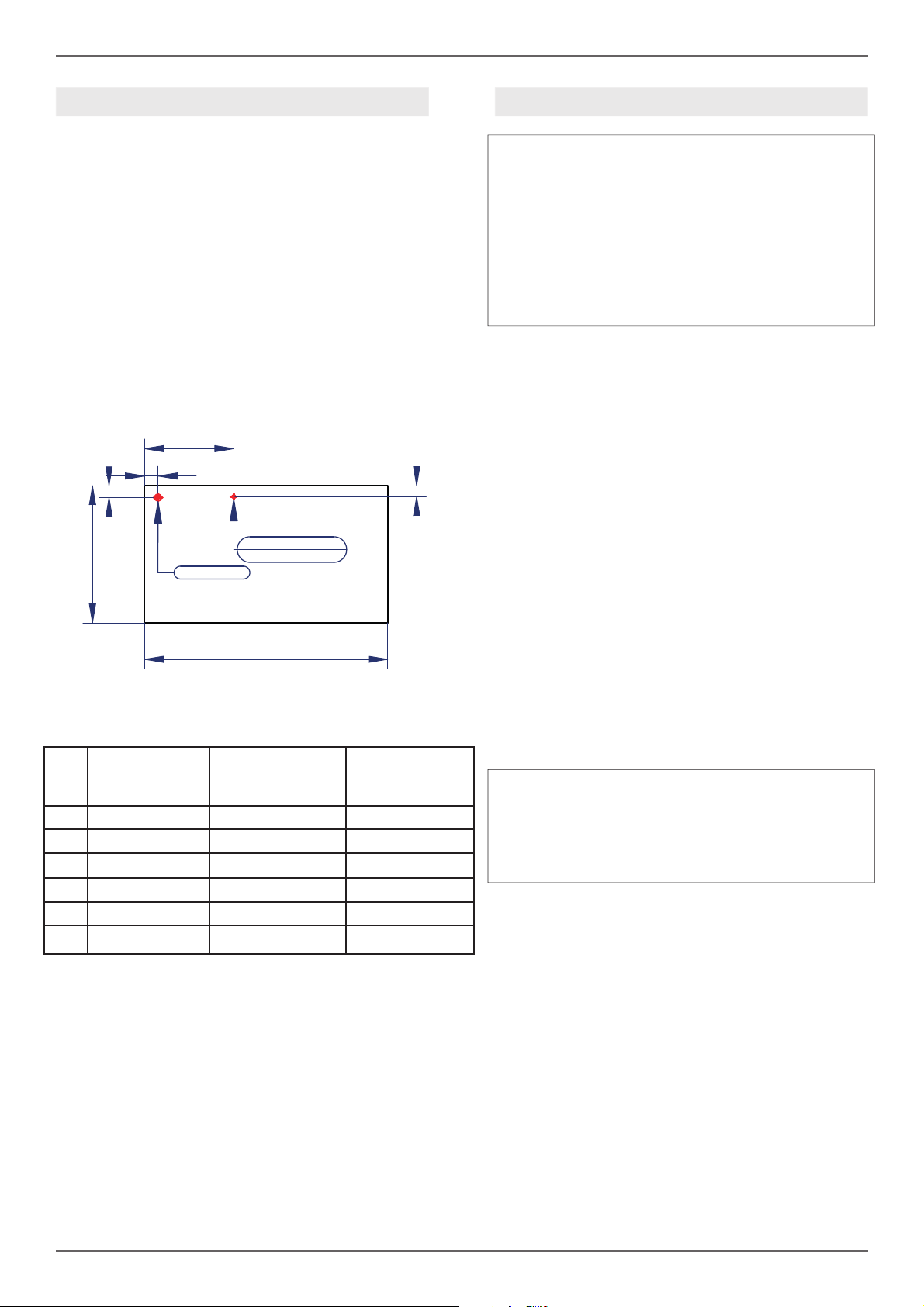
INSTALLATION REQUIREMENTS ELECTRICAL CONNECTION
GAS INLET
ELECTRIC
CONNECTION
L10
A
D
B
L1
C
COOKTOP
24”
COOKTOP
30”
COOKTOP
36”
A 1”3/4(45mm) 5”5/8(143mm) 1”7/8(47mm)
B 1”5/8(41mm) 1”5/8(41mm) 1”5/8(41mm)
C 12”1/4(311mm) 15”11/16(399mm) 12”1/4(312mm)
D 1”1/2(38mm) 1”1/2(38mm) 1”1/2(38mm)
L1 18”7/8”(480) 18”7/8”(480) 18”7/8(480mm)
L10 22”1/16(560) 22”1/16(560) 33”7/16(850mm)
Loading ...
Loading ...
Loading ...