Honda 2019 FourTrax Foreman Rubicon 4x4 EPS
Product's Documents
Below are documents related to this product, you can read online or download:
- User Manual - (English) Read Online | Download pdf
User manual Scooter
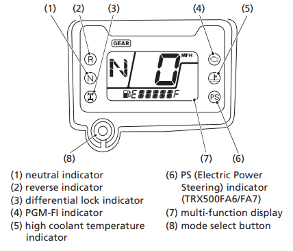
The indicators and displays on your ATV keep you informed, alert you to possible problems, and make your riding safer and more enjoyable. Refer to the indicators frequently. Their functions are described on the following pages.
Lamp Check
Initial lamp check:
The indicators come on for a few seconds and then go off when you turn the ignition switch to ON (I).
TRX500FA6/FA7:
The PS (Electric Power Steering) indicator comes back on and remains on until the engine is started after initial lamp check.
The high coolant temperature indicator and PGM-FI indicator comes back on for a few seconds and then go off after initial lamp check.
These indicators are identified in the table on page 17 with the words: Lamp Check.
When applicable, the reverse or neutral indicators come back on and remain on until you shift out of reverse or neutral after initial lamp check.
When applicable, the differential lock indicator comes back on and remains on until you shift out of the front differential lock mode after initial lamp check.
If one of these indicators does not come on when it should, have your dealer check for problems.
Display Check
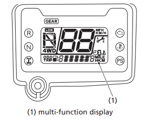
When the ignition switch is turned on, the multi-function display (1) will temporarily show all the modes and digital segments and initial message. So you can make sure the liquid crystal display is functioning properly.
The displays are identified in the table on page 18 with the words: Display Check.
If any part of these displays does not come on when it should, have your dealer check for problems.
Meter Input Signal Failure
If the neutral indicator, reverse indicator, differential lock indicator, PGM-FI indicator, high coolant temperature indicator stay on and the gear position indicator “–” and coolant temperature gauge “C – – – – – H” blink, have your dealer check for problems.
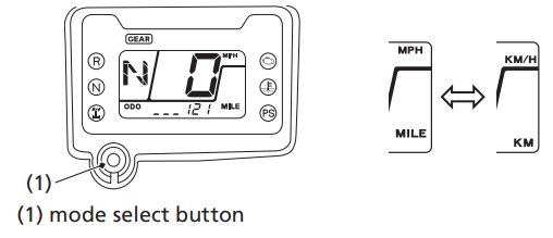
The multi-function display (1) includes the following functions:
| 4WD indicator | Odometer |
| Gear position indicator | Tripmeter |
| LOW indicator | Coolant temperature gauge |
| Speedometer | Hour meter |
| Maintenance minder indicator | Maintenance tripmeter |
| Fuel gauge | Maintenance hour meter |
| Digital clock |
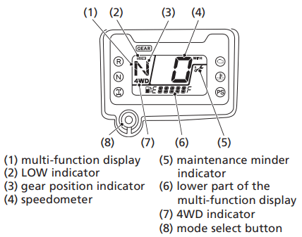
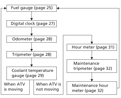
The lower part of the multi-function display (6) shows the fuel gauge, digital clock, odometer, tripmeter, coolant temperature gauge, hour meter, maintenance tripmeter or maintenance hour meter. To change the lower part of the multi-function display, push the mode select button (8).
Each time you press the mode select button, mode will change as shown in the illustration.
If there is a fuel warning with your ATV, the display will automatically change to the fuel gauge.
If you try to change the display back to ordinary display, it will automatically return to the fuel gauge.
If there is a coolant temperature warning with your ATV, the display will automatically change to the coolant temperature gauge. If you try to change the display back to ordinary display, it will automatically return to the coolant temperature gauge.
The speedometer, odometer, tripmeter and maintenance tripmeter show in either “MPH” and “MILE” or “KM/H” and “KM”.
To change the speed and mileage units, press and hold the mode select button (1) for more than 5 seconds in odometer mode (page 28) with the ATV stopped.
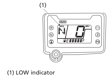
The LOW indicator (1) will be displayed when low (L) range is engaged with the ignition switch in the ON (I) position (page 95).
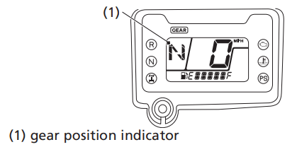
The gear position indicator (1) shows the gear position when the ignition switch is in the ON (I) position.
AUTO (automatic shift mode)
The indicator displays N for neutral, R for reverse, and D for drive.
ESP (manual shift mode)
The indicator displays N for neutral, R for reverse, and 1 – 5 for the five forward gears.
“–” will be displayed on the gear position indicator when the transmission is not shifted into gear properly. Before riding, check that the gear position is properly displayed on the gear position indicator.
If the gear position indicator shows “–” or blinks, turn the ignition switch to the OFF (O) position, and then turn it back to the ON (I) position again. If the gear position indicator still shows “–”, check that the range select lever is securely in a gear, rock the vehicle back and forth. Make sure the gear position is properly displayed in the gear position indicator, if the gear position indicator still shows “_” or blinks, see your dealer.
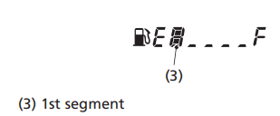
The fuel gauge (1) shows the approximate fuel supply available with the fuel mark (2). The fuel tank capacity is:
3.88 US gal (14.7 ℓ)
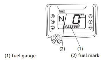
Regardless of what mode the display is in, when the fuel level reaches only 1st segment (3), the display will automatically switch to the fuel gauge display. You should refuel as soon as possible.
The amount of fuel remaining when the fuel gauge reaches the 1st segment is approximately:
1.82 US gal (6.9 ℓ)
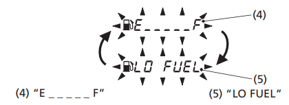
When the fuel gauge show “E _ _ _ _ _ F” (4) and “LO FUEL” (5) blink 3 times alternately and fuel mark blinks, you should refuel as soon as possible.
The amount of fuel reserve is approximately:
1.29 US gal (4.9 ℓ)
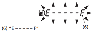
Fuel gauge failure:
If the fuel gauge E - - - - - F (6) is blinking, the fuel gauge function has failed. See your dealer.
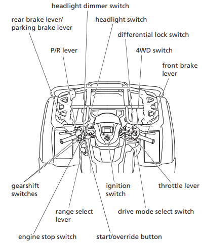
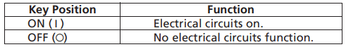
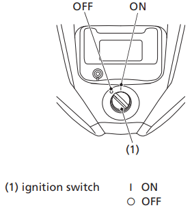
The ignition switch (1) is used for starting and stopping the engine (page 82). Insert the key and turn it to the right for the ON (O) position.
The ignition switch is also used to reset the maintenance tripmeter and the maintenance hour meter (page 34).
CENTER OF HANDLEBAR
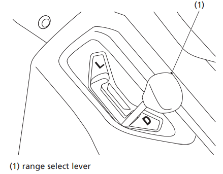
The range select lever (1) has two positions: Drive (D), Low (L). See Shifting Gears, page 95.
LEFT SIDE OF FUEL TANK
LEFT HANDLEBAR
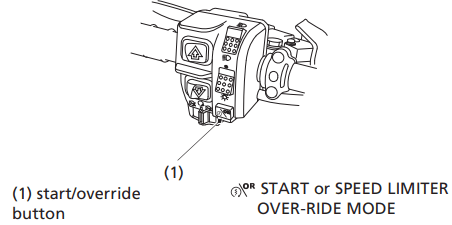
The start/override button (1) is used for starting the engine and activate the speed limiter over-ride mode. Pushing the button in starts the engine. See Starting Procedure, page 84.
When the engine is not running and the start/override button is pushed, the starter motor will crank the engine. The starter motor will not operate if the engine stop switch is in the OFF ( ) position when the start/override button is pushed.
To activate the speed limiter over-ride mode, see Front Differential Lock and Speed Limiter Over-Ride (Differential Lock Switch and Start/ Override Button), page 38.
LEFT HANDLEBAR

The engine stop switch (1) is used to stop the engine in an emergency. To operate, slide the switch to the OFF () position. The switch must be in the RUN ( ) position to start the engine, and it should normally remain in the RUN () position even when the engine is OFF.
If your ATV is stopped with the ignition switch ON (I) and the engine stop switch OFF (), the battery will discharge. Turn the ignition switch to OFF (O) to prevent battery discharge.
RIGHT HANDLEBAR

The throttle controls engine rpm (speed). To increase engine rpm, press the throttle lever (1) with your thumb. To reduce engine rpm, release pressure on the throttle lever. The throttle will automatically return to the closed position (engine idle) when you remove your thumb.
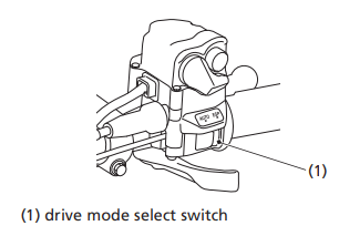
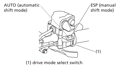
The drive mode select switch (1) has two positions: AUTO (automatic shift mode) and ESP (manual shift mode).
See Shifting Gears, page 89.
RIGHT HANDLEBAR
Always follow the proper starting procedure described below.
For your safety, avoid starting or operating the engine in an enclosed area such as a garage. Your ATV’s exhaust contains poisonous carbon monoxide gas which can collect rapidly in an enclosed area and cause illness or death.
If you turn the ignition switch to the OFF (O) position while in reverse, the transmission will automatically return to neutral (N) when the ignition switch is turned to the ON (I) position.
The starter motor will operate when the transmission is in neutral or the front brake lever is pulled in.

1. Before starting, make sure the vehicle is on a level surface and lock the parking brake (page 49).
2. Turn the ignition switch (1) to ON (I).
Confirm the following:
• The transmission is in neutral, and the neutral indicator (2) is ON and the gear position indicator shows “N”.
• The engine stop switch (3) is set to RUN ().
This ATV is fuel-injected with an automatic choke.
Follow the procedure indicated below.
Any Air Temperature
• With the throttle completely closed, press the start/override button.
The engine will not start if the throttle is fully open (because the electronic control module cuts off the fuel supply).
Snapping the throttle or fast idling for more than 5 minutes may cause exhaust pipe and muffler discolorations.
Normal Engine Stop
To stop the engine, make sure the transmission is in neutral by checking that the neutral indicator light is on, then turn the ignition switch to OFF (O).
The engine stop switch should normally remain in the RUN () position even when the engine is OFF.
If your ATV is stopped with the engine stop switch OFF () and the ignition switch ON (I), the battery will discharge.
Emergency Engine Stop
To stop the engine in an emergency, use the engine stop switch. To operate, slide the switch to either OFF () position.
Your ATV has two shift modes: AUTO (automatic shift mode) and ESP (manual shift mode).
You can select the desired shift mode with the drive mode select switch.
AUTO (automatic shift mode):
Use this mode for everyday riding. The transmission automatically shifts to keep the engine at the best speed for riding condition. The gear position indicator shows “D” for forward gears, “N” for neutral, and “R” for reverse. Select gear position with the gear shift switches.
ESP (manual shift mode):
In this mode, you can shift gears much like a manual transmission, but without operating a clutch.
You can select five forward gears neutral and reverse by operating the gearshift switches.
The gear position indicator will show “1, 2, 3, 4, or 5” for forward gears, “N” for neutral, and “R” for reverse.
When you tow a trailer, select the 1st shift position for proper performance.
Drive mode select (AUTO/ESP)
The drive mode select switch (1) is located on the right handlebar. To select the drive mode, release the throttle, then slide the drive mode select switch to the desired position. With the throttle fully closed, the drive mode can be changed while riding.
RIGHT HANDLEBAR
Gear Position selection AUTO (D/N/R), Manual (1-5/N/R)
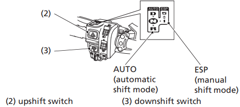
Two gearshift switches are located next to the left handlebar grip: upshift ( ) and downshift (
 ).
).
To shift between a forward gear (D or 1), neutral (N), or reverse (R), bring the ATV to complete stop, and press a shift switch to select gear position.
Select neutral (N) when you start the engine, or if it is necessary to stop briefly with the engine idling.
The gear position indicator shows “N”.
To select a forward gear (D or 1) from neutral (N), press the upshift switch (2) once.
• In AUTO (automatic shift mode) the gear position indicator shows “D”
• In ESP (manual shift mode) the gear position indicator shows “1”
To select reverse (R) from neutral (N), use the P/R lever and press the downshift switch (3) once. See Riding in Reverse (page 96).
LEFT HANDLEBAR
Driving in AUTO (automatic shift mode):
After starting the engine and letting it warm up, follow these procedures:
1. With the transmission in neutral, release the parking brake (page 50), but continue to squeeze the rear brake lever/parking brake lever.
2. With the throttle closed, select AUTO (automatic shift mode), and then press the upshift switch once to shift into drive (D).
3. The gear position indicator shows “D”.
4. Release the rear brake lever/parking brake lever and increase engine speed by gradually opening the throttle.
Driving in ESP (manual shift mode).
After starting the engine and letting it warm up, follow these procedures:
1. With the transmission in neutral, release the parking brake (page 50), but continue to squeeze the rear brake lever/parking brake lever.
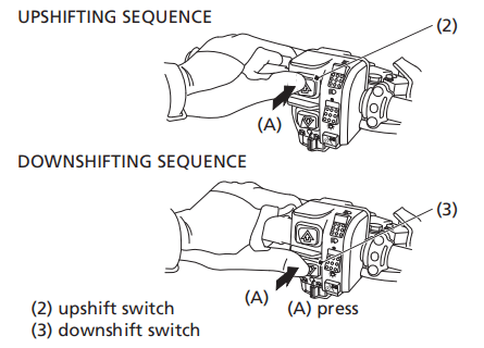
2. With the throttle closed, select ESP (manual shift mode), and then press the upshift switch ( ) (2) once to shift into 1st gear.
3. The gear position indicator shows “1”.
4. Release the rear brake lever/parking brake lever and increase engine speed by gradually opening the throttle.
5. When speed increases, release the throttle and upshift to 2nd gear by pressing the upshift switch once.
6. Repeat this sequence to progressively upshift to 3rd, 4th and 5th (top) gear.
7. To downshift, press the downshift switch ( ) (3) once. Remember to close the throttle each time you shift to the next lower gear.
The transmission cannot be upshifted from neutral to 1st gear or Dmode when the engine speed is above 2,300 rpm or the ground speed is above 2 mph (3 km/h).
The transmission cannot be downshifted from 1st gear or D-mode to neutral when the ground speed is above 1 mph (1.5 km/h) or engine speed is above 2,300 rpm.
In ESP (manual shift mode), if the ground speed decreases under a set speed (see table) the transmission will automatically downshift to the next lower gear.
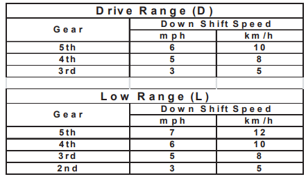
If the ATV is at a complete stop, 2nd gear, 3rd gear, 4th gear or 5th gear cannot be selected.
If the electric shift system malfunctions, the transmission cannot be shifted by pressing the gearshift switches. See your dealer. (In an emergency, a gear may be selected manually so you may move the vehicle. See Emergency Gear Selection & Operation, page 224).
Refer to Safety Precautions on page 119.
Fuel Recommendation

Use only unleaded fuel in your Honda. If you ride your Honda in a country where leaded fuel might be available, take precautions to use only unleaded fuel.
Your engine is designed to use any unleaded gasoline that has a pump octane number of 86 or higher. Gasoline pumps at service stations normally display the pump octane number. For information on the use of oxygenated fuels, see page 254.
Use of lower octane gasoline can cause persistent “pinging” or “spark knock” (a loud rapping noise) which, if severe, can lead to engine damage. Light pinging experienced while operating under a heavy load, such as climbing a hill, is no cause for concern.
If pinging or spark knock occurs at a steady engine speed under normal load, change brands of gasoline. If pinging or spark knock persists, consult your dealer.
Never use stale or contaminated gasoline or an oil/gasoline mixture. Avoid getting dirt, dust, or water in the fuel tank.
Fuel Capacity
Fuel tank capacity, including reserve:
3.88 US gal (14.7 ℓ)
Reserve capacity:
1.29 US gal (4.9 ℓ)
When there is only one segment left in the fuel gauge (page 25), fuel will be low and you should refuel as soon as possible.
Refueling Procedure
Refer to Safety Precautions on page 119.
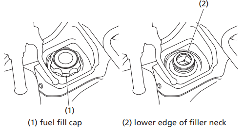
1. To open the fuel fill cap (1), turn it counterclockwise.
2. Add fuel until the level reaches the lower edge of the filler neck (2).
Avoid over filling the tank. There should be no fuel in the filler neck.
3. After refueling, turn the fuel fill cap clockwise securely.
If you replace the fuel fill cap, use a Honda Genuine replacement part or equivalent.
NOTICE Gasoline can damage the matte and camouflage coating. Do not allow spilled gasoline to pool on matte and camouflage colored bodywork. Also do not allow gasoline soaked rags to be placed on matte and camouflage bodywork.
Engine oil quality is a major factor that affects both the performance and the service life of the engine.
Using the proper oil (page 138) and filter, and regularly checking, adding, and changing oil will help extend your engine’s life. Even the best oil wears out. Changing oil helps get rid of dirt and deposits in the engine. Operating the engine with old or dirty oil can damage your engine. Running the engine with insufficient oil can cause serious damage to the engine and transmission.
Change the engine oil as specified in the maintenance schedule on page 122. When running in very dusty conditions, oil changes should be performed more frequently than specified in the maintenance schedule.
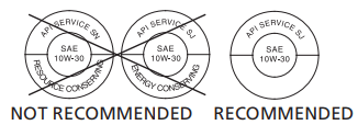
Oil Recommendation
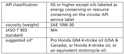
* Suggested oils are equal in performance to SJ oils that are not labeled as energy conserving or resource conserving on the circular API service label.
• Your ATV does not need oil additives. Use the recommended oil.
• Do not use oils with graphite or molybdenum additives. They may adversely affect clutch operation.
• Do not use API SH or higher oils displaying a circular API “energy conserving” or “resource conserving” service label on the container. They may affect lubrication and clutch performance.
• Do not use non-detergent, vegetable, or castor based racing oils.
Checking & Adding Oil
Refer to Safety Precautions on page 119.
Check the engine oil level each day before operating your ATV and add if needed.
The dipstick is located at the front left crankcase cover.
The dipstick is located at the front left crankcase cover.
1. Park your ATV on a firm, level surface.
2. Start the engine in a well-ventilated area and let it idle for 3 – 5 minutes. If the air temperature is below 10°C (50°F), let the engine idle for an additional 5 minutes (a total of 10 minutes).
3. Stop the engine and wait for 2 – 3 minutes.
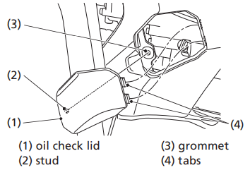
4. Remove the oil check lid (1) by disengaging the stud (2) from the grommet (3) and releasing the tabs (4) from the slits.
LEFT SIDE
5. Remove the dipstick (5) from the front left crankcase cover and wipe it clean.
6. Insert the dipstick without screwing it in, then remove the dipstick and check the oil level. The oil level should be between the upper level mark (6) and the lower level mark (7) on the dipstick.
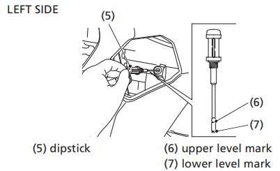
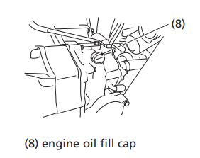
7. If the oil level is near or below the lower level mark, remove the seat (page 130) and the tank cover assembly (page 132). Remove the engine oil fill cap (8) from the front right crankcase cover and add the specified oil into the fill cap hole, up to the upper level mark on the dipstick. Do not over fill.
8. Reinstall the engine oil fill cap and dipstick.
9. Install the tank cover assembly.
10. Install the seat.
11. Install the oil check lid.
NOTICE Running the engine with an improper oil level can cause serious engine damage.
RIGHT SIDE
Dust Cover
Dust Cover
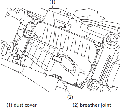
Do not push the dust cover (1) too far into the breather joint (2). If the dust cover is dirty, clean it.
Air Cleaner Housing Drain Tube
The air cleaner housing drain tube should be serviced in accordance with the Maintenance Schedule. (Riding through water may require more frequent inspection.) If deposits can be seen in the drain tube, the tube must be cleaned before starting the vehicle.
REAR
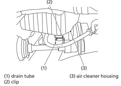
1. Remove the drain tube (1) by removing the clip (2) under the air cleaner housing (3).
2. Drain the deposits.
3. Reinstall the drain tube, securing it with the clip.
To safely operate your ATV, your tires must be the proper type and size, in good condition with adequate tread, and correctly inflated.
This ATV is equipped with low pressure tubeless tires. Although the tires are designed specifically for off-road use, they are not immune to punctures. Always select your riding area with care.
The following pages give detailed information on how and when to check your air pressure, how to inspect your tires for wear and damage, and our recommendations for tire repair and replacement.
Air Pressure
Refer to Safety Precautions on page 119.
Properly inflated tires provide the best combination of handling, tread life, and riding comfort. Generally, underinflated tires wear unevenly, adversely affect handling, and are more likely to fail from being overheated. Overinflated tires make your ATV ride harshly, are more prone to damage from surface hazards, and wear unevenly.
Make sure the air valve caps are secure. If necessary, install new caps.
Always check air pressure when your tires are “cold.” If you check air pressure when your tires are “warm” — even if your ATV has only been ridden for a few miles — the readings will be higher. If you let air out of warm tires to match the recommended cold tire pressures, the tires will be underinflated. Be sure to check tire pressure at the riding site, since changes in altitude can affect air pressure.
The recommended “cold” tire pressures are:
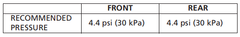
A manually operated tire pump should be used rather than the high pressure system found in service stations. This will minimize the possibility of tire damage from overinflation. If you use a high pressure system at a service station, add air in small amounts and check the pressure increase frequently to prevent possible tire damage from overinflation.
Inspection
Refer to Safety Precautions on page 119.
Whenever you check the tire pressures, you should also look for:
• Bumps or bulges in the side of the tire or the tread. Replace any tire that has a bump or bulge.
• Cuts, slits, or cracks in the tires. Replace the tire if you can see fabric or cord.
• Nails or other foreign objects embedded in the side of the tire or tread.
• Excessive tread wear.
Also, if you hit a pothole or other hard object while riding, stop as soon as you safely can and carefully inspect the tires for damage.
Tread Wear
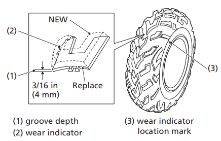
To check the condition of a tire tread, measure the groove depth (1) in the center of the tire, or check the wear indicator (2).
For best performance, you should replace a tire before the tread depth at the center reaches the following limits:
Tire Repair
Refer to Safety Precautions on page 119.
A tire that is repaired, either temporarily or permanently, will have lower speed and performance limits than a new or undamaged tire.
A temporary repair can sometimes be made in an emergency situation. However, since a temporary repair may not hold, you must ride very slowly, preferably without any cargo, and have the tire replaced or permanently repaired as soon as possible. (For more information on temporary repairs, see If You Have a Flat Tire, page 226.)
A permanent repair, such as an internal plug patch, can be made if a tire has only a small puncture in the tread area. However you may not be able to safely carry as much weight. If you choose to have a tire repaired, be sure the repair work is performed by a professional.
If you have a tire professionally repaired at a non-Honda facility, we recommend that you have the work checked by your dealer.
Your ATV has a maintenance-free type battery. You do not have to check the battery electrolyte level or add distilled water as you would with a conventional-type battery.
NOTICE Your battery is a maintenance-free type and can be permanently damaged if the cap strip is removed.
Electrical accessories use current from the battery, even when the ignition is OFF (O). Limited operation also allows the battery to discharge.
If you have electrical accessories on your ATV or do not ride frequently, we recommend that you charge the battery frequently (see Battery Charging, page 198).
If you do not expect to ride your ATV for at least two weeks, we recommend you remove the battery, or at least disconnect the battery cables (negative cable first).
If you plan to store your ATV, see Battery Storage, page 195.
If your battery seems weak and/or is leaking electrolyte (causing slow starting or other electrical problems), see your dealer.
WARNING: Battery posts, terminals and related accessories contain lead and lead compounds. Wash your hands after handling.
Battery Storage
Refer to Safety Precautions on page 119.
If you plan to store your ATV, we recommend you remove the battery and store it where it can be charged at least every 30 days to maintain its service life.
If you do not remove the battery, we recommend disconnecting the battery cables (negative cable first).
You will get the best storage results from removing the battery and slow charging it every 30 days (see Battery Charging, page 198).
Before you remove the battery, be sure to read all the information that follows, as well as the information on the battery label.
The battery is located in a compartment under the rear fender cover.
UNDER REAR FENDER COVER
Removal
1. Make sure the ignition switch is OFF (w).
2. Remove the seat (page 130).
3. Remove the rear fender cover (page 131).
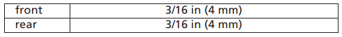
4. Release the rings and remove the rubber band (1).
5. Disconnect the negative (–) terminal lead (2) from the battery (3) first, then disconnect the positive (+) terminal lead (4).
6. Remove the battery taking care not to drop the terminal nuts (5).
7. Charge the battery (see following section).
8. Store your battery in an easy-to-reach location off the floor, in an area protected from freezing temperature and direct sunlight.
9. Clean the compartment after removing the battery for storage. Dry the compartment.
10. Slow charge the battery (see following section) once every 30 days.
Installation
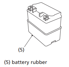
1. Check that the battery rubber (5) for damage. If necessary, replace the battery rubber.
2. Make sure the battery rubber is properly installed.
3. Reinstall the battery in the reverse order of removal. Be sure to connect the positive (+) terminal first, then the negative (–) terminal.
4. Make sure all bolts and other fasteners are secure. 5. Install the removed parts in reverse order of removal.
After the battery is reconnected, check the clock. Readjust the clock if necessary (page 27).
Battery Charging
Refer to Safety Precautions on page 119.
Be sure to read the information that came with your battery charger and follow the instructions on the battery. Improper charging may damage the battery.
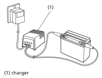
We recommend using a charger (1) designed specifically for your Honda, which can be purchased from your dealer. These units can be left connected for long periods without risking damage to the battery. However, do not intentionally leave the charger connected longer than the time period recommended in the charger’s instructions. Avoid using an automotive-type battery charger. An automotive charger can overheat an ATV battery and cause premature damage.
Proper operation and maintenance can prevent starting and engine performance problems. In many cases, the cause of the problem may be a simple operational oversight.
If you have a problem starting the engine — or experience poor engine performance — the following information may help you. If you can’t correct the problem, see your dealer.
If your ATV won’t start, listen as you press the start/override button. If you don’t hear the starter motor turning, refer to the Starter motor doesn’t operate symptom. If you can hear the starter motor working normally, refer to the Starter motor works, but the engine won’t start symptom.
SYMPTOM: Starter motor doesn’t operate.
POSSIBLE CAUSE | WHAT TO DO |
| ignition switch OFF | Turn the ignition switch ON. |
| engine stop switch OFF | Slide the engine stop switch to RUN. |
| transmission not in neutral | Shift into neutral or squeeze the front brake lever. |
| blown fuse | Replace with a new fuse of the same rating (page 232). |
| battery lead loose | Tighten the battery lead. |
| low (or dead) battery | Charge the battery (page 198). If charging doesn’t help, see your dealer. |
| faulty starter motor | If all possible causes are negative, the starter motor may be faulty. See your dealer. |
SYMPTOM: Starter motor works, but the engine won’t start.
POSSIBLE CAUSE | WHAT TO DO |
| out of fuel | Fill the fuel tank. |
| flooded engine | See Flooded Engine (page 85). |
| loose or unconnected spark plug cap | Install the spark plug cap securely. If the engine still won’t start, see your dealer. |
| loose battery cables | Tighten the battery terminal bolts. |
| weak battery | Charge the battery (page 198). If charging doesn’t help, see your dealer. |
SYMPTOM: Engine starts, but runs poorly.
POSSIBLE CAUSE | WHAT TO DO |
| high coolant temperature | Check the coolant temperature gauge and high coolant temperature indicator. Refer to If the High Coolant Temperature Indicator Lights, page 230. |
| runs erratically, misfires | See your dealer. |
| blubbers (rich fuel mixture) | See your dealer. |
| sooty exhaust (rich fuel mixture) | See your dealer. |
| detonates or pings under load | If applicable, switch to the recommended octane gasoline (page 134) or change your brand of gasoline. If the problem persists, see your dealer. |
| afterfires (backfires) | See your dealer. |
| pre-ignition (runs on after ignition switched OFF) | See your dealer. |
SYMPTOM: Engine starts, but runs poorly or dies when hot.
POSSIBLE CAUSE | WHAT TO DO |
| poor or inadequate fuel flow due to clogged fuel filter | See your dealer. (ensure clean fuel supply) |
ESP (manual shift mode):
If one or both shift switches do not function, see the following instruction. If proper function cannot be restored, see your dealer.
1. Stop the ATV.
2. Turn the ignition switch to the OFF (O) position.
3. After the engine stops, turn the ignition switch to the ON (I) position.
4. Press both shift switches and check that they are functioning.
5. If both switches are functioning, shift into neutral and restart the engine.
If one or both switches are not functioning, see Emergency Gear Selection & Operation, page 224.
AUTO (automatic shift mode):
When the automatic transmission is not shifting properly, the gear position indicator will show “–” and blink.
See your dealer to check and restore the automatic transmission.
If the gear position indicator shows “–” and blink while riding, perform the following:
1. Stop the ATV.
2. Turn the ignition switch to the OFF (O) position.
3. After the engine stops, turn the ignition switch to the ON (I) position.
4. Check the gear position indicator.
If these efforts do not restore proper operation, have your ATV inspected by your dealer.
When the “–” is blinking in the gear position indicator:
Restart the engine; drive the ATV to a location where it can be loaded and transported to your dealer.
When the display on the gear position indicator returns to normal:
You may drive on the ATV as usual after restarting the engine. However, we urge you to have your ATV inspected by your dealer.
If the ATV does not move, even through “–” is not blinking in the gear position indicator:
If your ATV won’t move, it is possible the transmission system has malfunctioned. Use the following procedure to manually over-ride the clutch of the transmission.
1. Shift the transmission into 2nd gear.
2. Apply the parking brake (page 50).
3. Turn the ignition switch to the OFF (w) position.
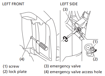
4. Loosen the screw (1) and release the lock plate (2).
5. Locate the emergency valve access hole (4) inside the left front fender. Using a screwdriver, turn the emergency valve (3) all the way in. With the engine running, slowly open the throttle to move the ATV forward.
6. See your dealer as soon as possible.
When the battery is low (or dead):
• See If the Battery Is Low (or Dead), page 239.
If the shift switches do not operate, use the following procedure to manually select a gear so you may drive the vehicle to a location where it can be loaded and transported to your dealer.
1. Turn the ignition switch to the ON (q) position.
2. Remove the seat (page 130) and tank cover assembly (page 132).
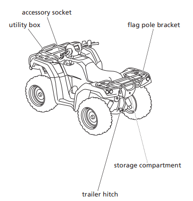
3. Remove the gear change tool from the storage compartment (page 128).
4. Check the neutral indicator. If the transmission is in neutral, go to step 5. If the transmission is not in neutral, use the gear change tool to shift to neutral so you will be able to start the engine. Refer to How to Shift Gears Manually: (page 225).
5. Apply the parking brake (page 50).
6. Press the start/override button to start the engine.
7. Set 2nd gear position. Refer to How to Shift Gears Manually: (page 225).
8. Return the gear change tool to the storage location.
9. Install the tank cover assembly and seat.
10. Get on the ATV, release the parking brake, and drive it at a safe speed to a place where it can be repaired or serviced.
How to Shift Gears Manually:
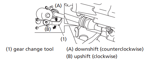
• With the ATV unoccupied, align the hexagonal hole of the gear change tool (1) with the hexagonal end of the secondary spindle which is located on the front crankcase next to the front propeller shaft.
• To downshift, turn the gear change tool to counterclockwise (A). To upshift, turn the gear change tool to clockwise (B).
• If the transmission does not shift, rock the vehicle back and forth and try again.
• Return the gear change tool to the storage location.
Do not attempt to shift gears manually using the gear change tool while riding.
If the transmission is shifted manually when the electric shift system is functioning, the system will shutdown automatically and the shift switches will not operate. To reactivate the system, turn the ignition switch to the OFF (O) position, then turn it back to the ON (I) position.
It may be required to rock the ATV back and forth to get proper transmission gear alignment to allow shifting between gears.
How you handle a flat tire on the trail depends on how serious the tire damage is, and what tools and supplies you have with you.
If you have a slow leak or a minor puncture, use the plug method to make a temporary repair. (The plug method is applied from the outside of the tire and is the same as that for conventional tubeless tires.)
A plug-type repair kit, available at most auto parts stores or service stations, provides a plug, an installation tool, tire cement, and an instruction sheet. Follow the instructions provided with the repair kit to make a temporary repair.
As soon as possible, have the tire permanently repaired by your dealer. Any tire that cannot be repaired should be replaced.
Whenever the ATV is to be operated far from service facilities or available transportation, we recommend that you carry a tire pump and a repair kit with the vehicle.
If the leak is more serious, or a temporary repair doesn’t hold, the tire must be replaced. The tire will also need to be replaced if it is damaged (page 191). Replacing a tire involves removing and reinstalling the wheel (page 228).
If you are unable to repair a flat tire on the trail, you will need to send for help. We strongly recommend that you do not try to ride with a flat tire. The ATV will be hard to handle, and if the tire comes off the rim, it may lock up the wheel and cause you to crash.
Emergency Wheel Removal/Installation
Refer to Safety Precautions on page 119.
Removal
1. Park your ATV on a firm, level surface.
2. Loosen — but do not remove — the wheel nuts (1).
3. Raise the front (or rear) wheels off the ground and place a support block under the vehicle.
4. Remove the wheel nuts.
5. Remove the wheel.
• Avoid getting grease, oil, or dirt on the front brake disc or pad surfaces when removing and installing each wheel. Any contamination can cause poor brake performance or rapid pad wear after reassembly.
Installation
1. Position the wheel.
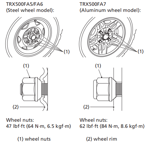
2. Position each wheel nut so that the tapered side faces the wheel rim (2).
3. Hand-tighten the wheel nuts on the wheel, then lower the ATV to the ground before tightening the nuts in a crisscross (rather than circular) pattern to the specified torque:
TRX500FA5/FA6 (Steel wheel model):
47 lbf·ft (64 N·m, 6.5 kgf·m)
TRX500FA7 (Aluminum wheel model):
62 lbf·ft (84 N·m, 8.6 kgf·m)
If a torque wrench was not used for installation, see your dealer as soon as possible to verify proper assembly. Improper assembly may lead to loss of braking capability.
Normally, the high coolant temperature indicator will only light momentarily when you turn the ignition to ON (I).
High coolant temperature may be caused by restriction of air flow to the radiator (such as mud caked on the radiator), extended idling, an oil leak, a coolant leak, a low oil level, a low coolant level, or extended operation under adverse conditions.
If the all segment of the coolant temperature gauge and high coolant temperature indicator are on while you’re riding, don’t ignore it. Pull safely to a stop. Stop the engine as soon as it’s safe to do so, and let it cool.
NOTICE Continuing to ride with high coolant temperature or an overheated engine can cause serious engine damage.
• A steaming engine indicates a coolant leak. Shut the engine off and wait until the steaming stops. Look for a leak, but don’t touch the engine or radiator system. Let everything cool off first.
• Check for any restriction of air flow to the radiator.
• If there’s no obvious problem, leave the engine on so the fan and coolant circulating system can continue working. Monitor the coolant temperature gauge and high coolant temperature indicator. The indicator may turn off after a brief stop with no load on the engine.
• Check the radiator fan.
If the fan is not working, turn the engine off. Open the fuse box (page 233) and check the radiator fan fuse. If the fuse is blown, replace it with the proper (same rating) spare fuse. Start the engine. If the all segment of the coolant temperature gauge and high coolant temperature indicator stays on, turn the engine off. If the radiator fan is working, visually check the coolant level in the reserve tank, located under the left front fender. It isn’t necessary to touch the radiator system.
• If the reserve tank is low or empty, don’t ride without adding coolant (page 152). After adding coolant, turn the engine on and check the coolant temperature gauge and high coolant temperature indicator.
If the indicator doesn’t turn off, do not ride. The engine needs repair.
Transport your ATV to your dealer (page 208).
If the temperature drops to normal, check the coolant level. If it has gone down, add more coolant.
• Check for an oil leak.
• Check the oil level. If necessary, add the recommended oil (page 140) to the upper level mark. If you must leave your ATV to get oil, secure it as much as possible.
• Start the engine, and check that the coolant temperature gauge and high coolant temperature indicator goes off.
If you are able to resume riding, continue to monitor the coolant temperature gauge and high coolant temperature indicator frequently.
If there is an oil leak — do not ride the ATV until the leak is repaired by your dealer (page 208).
If there’s a mild coolant leak, you can ride for awhile, carefully watching the coolant temperature gauge and indicator. Be prepared to stop and add more coolant or water. If the leak is bad, transport your ATV to your dealer (page 208).
All of the electrical circuits on your ATV have fuses to protect them from damage caused by excess current flow (short circuit or overload).
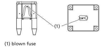
If something electrical on your ATV stops working, the first thing you should check for is a blown fuse (1).
Check all the fuses before looking elsewhere for another possible cause of the problem. Replace any blown fuses and check component operation.
The main fuse and the circuit fuses are located under the rear fender cover.
TRX500FA6/FA7:
The EPS (Electric Power Steering) fuse is located under the rear fender cover.
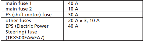
Recommended Fuses
Main Fuses Access
1. To prevent an accidental short circuit, turn the ignition switch to OFF (O) before checking or replacing the fuses.
2. Remove the seat (page 130).
3. Remove the rear fender cover (page 131).
4. To access the main fuse 1 (2), remove the fuse cover (3).
5. To access the main fuse 2 (4), remove the fuse box cover (5).
UNDER REAR FENDER COVER
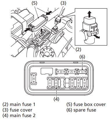
6. Pull the main fuses out.
If the main fuse 1 is blown, install the spare fuse (page 129).
If the main fuse 2 is blown, install the spare fuse (6).
7. Install the fuse cover.
Circuit Fuses Access
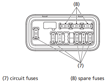
8. To check or replace a circuit fuse (7), pull the old fuse out of its retaining clips.
If the fuse is blown, replace it with a spare fuse (8) of the same rating.
If you do not have a replacement fuse with the proper rating for the circuit, install one with a lower rating.
NOTICE Replacing a fuse with one that has a higher rating greatly increases the chance of damage to the electrical system.
9. Install the fuse box cover.
10. Install the rear fender cover.
11. Install the seat.
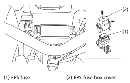
EPS (Electric Power Steering) Fuse Access (TRX500FA6/FA7)
1. Turn the ignition switch to OFF (O) before checking the fuse.
2. Remove the seat (page 130).
3. Remove the rear fender cover (page 131).
4. To access the EPS fuse (1), remove the EPS fuse box cover (2). If the EPS block fuse is blown, install the spare fuse (page 129).
5. Install the EPS fuse box cover.
6. Install the rear fender cover.
7. Install the seat.
UNDER REAR FENDER COVER
If you do not have a spare fuse and you cannot ride the ATV without fixing the problem, take a fuse of the same rating or a lower rating from one of the other circuits that you can do without temporarily.
If you replace a blown fuse with a spare fuse that has a lower rating, replace the fuse with the correct rating as soon as you can. Also remember to replace any spare fuses that were installed.
If the replacement fuse of the same rating burns out in a short time, there is probably a serious electrical problem on your ATV. Leave the blown fuse in that circuit and have your ATV checked by your dealer.
Personal safety is your first priority after a crash. If you or anyone else has been injured, take time to assess the severity of the injuries and whether it is safe to continue riding. If you cannot ride safely, send someone for help. Do not ride if you will risk further injury.
If you decide you are capable of riding safely, carefully inspect your ATV for damage and determine if it is safe to ride. Check the tightness of critical nuts and bolts securing such parts as the handlebar, control levers, brakes, and wheels.
If there is minor damage, or you are unsure about possible damage but decide to try riding the ATV back to your base, ride slowly and cautiously.
Sometimes, crash damage is hidden or not immediately apparent. When you get home, thoroughly check your ATV and correct any problems you find. Also, be sure to have your dealer check the frame and suspension after any serious crash.
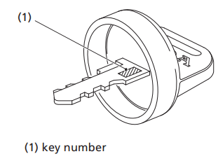
Be sure to record your key number (1). Store the spare key and recorded key number in a safe location. You’ll need this number to have a duplicate key made.
If you lose your key and aren’t carrying a duplicate, either get your spare or have one made. If you don’t know your key number, call the dealer where you purchased your Honda ATV. They may have it listed in their records. If they don’t, transport your ATV to them or the nearest dealer. The dealer will probably have to remove the ignition switch assembly to find the key number so they can make a key for you.
Jump starting is not recommended, especially if you use an automobile battery. The greater amperage of an automobile battery when the car engine is running can damage your ATV’s electrical system.
Bump starting is also not recommended.
If you can’t charge the battery or it appears unable to hold a charge, contact your dealer.
(Canada only)
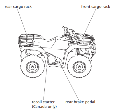
Your ATV will operate even if the battery is low (or dead), as long as the engine is running. If the engine is not running, it may be started using the recoil starter.
1. Turn the ignition switch to the ON (I) position.
2. Check if the transmission is in neutral by moving the vehicle back and forth.
3. If the transmission is in neutral, the vehicle will move easily. Go to step 6. If the transmission is not in neutral, the vehicle will not move.
4. Remove the gear change tool from the storage compartment (page 128).
5. Use the gear change tool to shift to neutral so you will be able to start the engine. Refer to How to Shift Gears Manually: (page 225).
6. Apply the parking brake.
7. Turn the ignition switch to the OFF (O) position, then turn it back to the ON (I) position.
8. Use the recoil starter (page 88) to start the engine.
The brake levers or pedal, control cables, and other components can be damaged as you ride in dense brush or over rocky terrain. Making a trailside repair depends on how serious the damage is and what tools and supplies you have with you.
• If any component of the brake system is damaged, you may be able to ride carefully back to your base using the other brake components for slowing or stopping.
• If you damage a throttle cable or other critical component, your ATV may be unsafe to ride. Carefully assess the damage and make any repairs that you can. But if there is any doubt, it’s best to be conservative and safe.