Loading ...
Loading ...
Loading ...
7
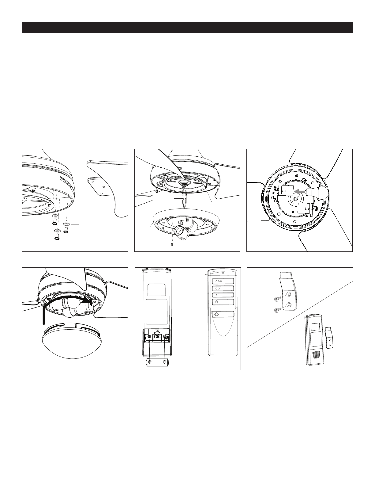
FINAL INSTALLATION
Figure 5.5
Figure 5.8
Figure 5.4
Figure 5.7
Figure 5.6
Figure 5.9
Glass Bowl
LED Indicator
Fitter Plate Screw
Fitter Plate Screw
Light Kit
Single-pin
Connector
Blade
Blade Washer
Blade Screw
Bulb
4. Insert blade through slot in the side of the motor assembly. Align the holes of one blade with three blade screw holes in underside
of the motor assembly. Secure with three blade screws and blade washers. Repeat this step for the remaining blades (Figura 5.4).
5. Remove one of the three fitter plate screws preassembled to the fitter plate and loosen the other two but do not remove. Connect
the single-pin connector from the tter plate to the single-pin connector from the light kit -- blue to black and white to white. Then,
align the two key slots in the light pan with the loosened fitter plate screws. Place the light pan over the two screws and turn the
light pan clockwise. Then tighten the two tter plate screws. Re-install the tter plate screw that was removed in the previous step,
and tighten firmly (Figure 5.5).
6. Install the two E26-base LED bulbs (Figure 5.6).
7. Attach the glass bowl to the light kit by twisting the glass bowl tightly in a clockwise direction until it is secure (Figure 5.7).
8. Remove the battery door from the back of the remote. Insert the battery from the remote pack into the remote; ensure polarity
of the battery matches the polarity indicated in the battery compartment -- positive (+) to positive (+) and negative (-) to
negative (-). Replace the battery door and press the Fan Power button to ensure the LED indicator illuminates and the remote
turns on the fan (Figure 5.8). Note: If the remote does not turn on the fan, see TROUBLESHOOTING (page 9)
9. If desired, the wall bracket in remote pack can be installed to a wall using the provided mounting screws. Store the remote on
the wall bracket when not in use (Figure 5.9).
Wall Bracket
Wall Bracket
Screw
Battery
Loading ...
Loading ...
Loading ...