Loading ...
Loading ...
Loading ...
Complete Installation
1. With dryer in nal position, place level on top of the dryer,
rst side to side; then front to back. If the dryer is not level,
adjust the legs of the dryer up or down until the dryer
is level.
2. Plug in dryer or reconnect power.
3. Check dryer operation:
Insert coins. Select a cycle. Using the WHITES & COLORS
cycle, let the dryer run for at least ve minutes. Dryer will
stop when time is used up.
NOTE: Dryer door must be closed for dryer to operate.
When door is open, dryer stops, but timer continues to run.
To restart dryer, close door and reselect a cycle.
4. If drying time is too long, make sure that the lint screen is
clean, and that there are no obstacles to airow in the dryer
vent system.
5. Now start the dryer and allow it to complete a full cycle
to make sure it is working properly.
Connect Vent
1. Using a 4" (102 mm) clamp, connect vent to exhaust outlet
in dryer. If connecting to existing vent, make sure the vent is
clean. The dryer vent must t over the dryer exhaust outlet
and inside the exhaust hood. Make sure the vent is secured
to exhaust hood with a 4" (102 mm) clamp.
2. Move dryer into nal position. Do not crush or kink vent,
and remove any excess exible vent to improve airow.
Make sure dryer is level.
21
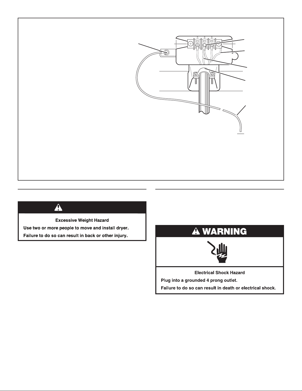
Optional,
3-wire connection:
Use for direct wire or power supply
cord where local codes do not permit
connecting cabinet-ground conductor
to neutral wire.
1. Remove center terminal block screw.
2. Remove neutral ground wire from
external ground conductor screw.
Connect neutral ground wire and the
neutral wire (white or center wire) of
power supply cord/cable under center
terminal block screw. Tighten screw.
3. Connect the other wires to outer terminal
block screws. Tighten screws.
4. Tighten strain relief screws.
5. Connect a separate copper ground wire
from the external ground conductor
screw to an adequate ground.
6. Insert tab of terminal block cover into
slot of dryer rear panel. Secure cover
with holddown screw.
C
B
A
D
E
F
A. External ground conductor screw
B. Center terminal block screw
C. Neutral ground wire
D. Neutral wire (white or center wire)
E. 3/4" (19 mm) UL listed strain relief
F. Grounding path determined by a qualied
electrician
WARNING
Loading ...
Loading ...
Loading ...