
Loading ...
Loading ...
Loading ...
TEC_TM_009 | REV. I | EN 03/21/2023 Page 37 of 76
TR-30/36 INSTALL MANUAL
PAGE TITLE
INSTALLATION
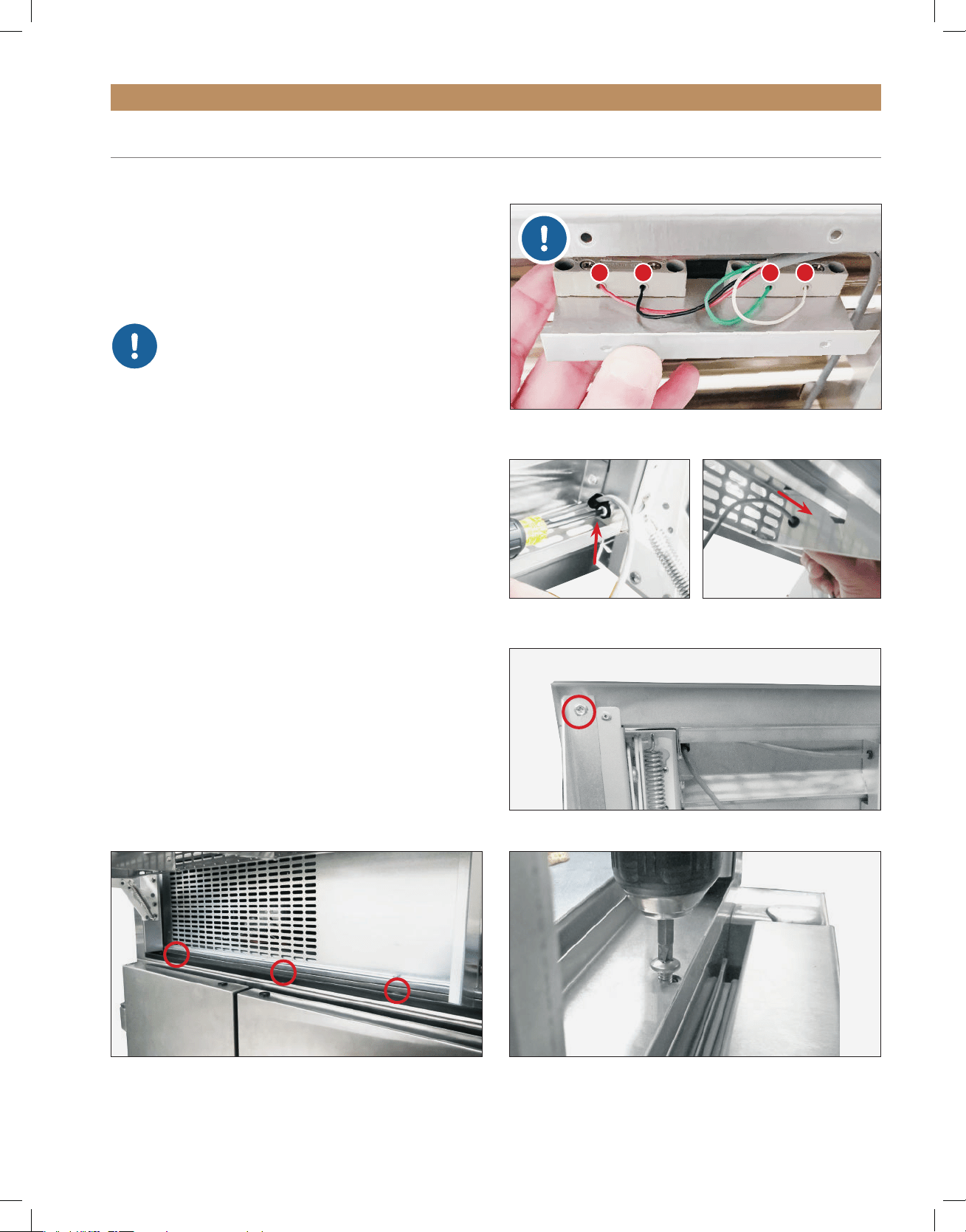
FIG. 9.
Rainshield screw locations.
FIG. 8.
Bracket screw location. Other bracket not shown.
FIG. 10.
Remove the screws from the metal channel.
JOINING KIT INSTALLATION (CONT.)
Kit Sizes: 60" (1524 mm) / 72" (1828.8 mm) / 78" (1981.2 mm) / 90" (2286 mm)
PROCEDURE
1. Remove the reed switch bracket. See figs. 2 and 3.
2. Remove the reed switch cover, and then
disconnect the reed switch. See figs. 4 and 5.
NOTE: IF FOUR (4) WIRES ARE
CONNECTED TO THE REED SWITCH,
BE SURE TO CLEARLY LABEL THE
WIRES’ ORIGINAL LOCATIONS BEFORE
DISCONNECTING THE REED SWITCH.
WIRE LOCATION IS CRITICAL TO THE
CABINET’S OPERATION. SEE FIG. 5.
3.
Remove the reed switch wire from the rainshield.
See figs. 6 and 7.
4. Remove the rainshield. See figs. 8-10.
5. Repeat steps 1-4 for each unit of the joined
installation.
6. Remove the inner magnet brackets (see figs. 11
and 12). Then, thread and tighten the magnet
bracket screws. Discard the magnet bracket.
NOTE: BE SURE TO RETURN MAGNET
BRACKET SCREWS TO THEIR ORIGINAL
POSITIONS; THE SCREWS SUPPORT THE
CASTOR ASSEMBLY HOUSING.
FIG. 6.
Remove the p-clip holding
the wire to the rainshield.
FI G . 7.
Pull the reed switch wire
through the rainshield bushing.
1 2 3 4
FIG. 5.
Label the original wire locations
BEFORE
disconnecting the reed
switch.
Loading ...
Loading ...
Loading ...