Version 12/08 - Page 1
MATRIX
Wall Mount Luxury Rangehood
READ AND SAVE THESE INSTRUCTIONS
READ THESE INSTRUCTIONS BEFORE YOU START INSTALLING THIS RANGEHOOD
WARNING: - TO REDUCE THE RISK OF A RANGE TOP GREASE FIRE: a) Never leave surface units unattended at high
settings. Boilovers cause smoking and greasy spillovers that may ignite. Heat oils slowly on low or medium setting. b)
Always turn hood ON when cooking at high heat or when ambeing food (i.e. Crepes Suzette, Cherries Jubilee, Pepper-
corn Beef Flambé). c) Clean ventilating fans frequently. Grease should not be allowed to accumulate on fan or lter. d)
Use proper pan size. Always use cookware appropriate for the size of the surface element.
WARNING: - TO REDUCE THE RISK OF INJURY TO PERSONS IN THE EVENT OF A RANGE TOP GREASE FIRE, OBSERVE
THE FOLLOWING: SMOTHER FLAMES with a close-tting lid, cookie sheet, or metal tray, then turn off the burner. BE
CAREFUL TO PREVENT BURNS. If the ames do not go out immediately EVACUATE AND CALL THE FIRE DEPARTMENT.
NEVER PICK UP A FLAMING PAN - You may be burned. DO NOT USE WATER, including wet dishcloths or towels - a
violent steam explosion will result. Use an extinguisher ONLY if: 1. You know you have a Class ABC extinguisher, and
you already know how to operate it. 2. The re is small and contained in the area where it started. 3. The re department
is being called. 4. You can ght the re with your back to an exit.
LISEZ BIEN CETTE FICHE AVANT D'INSTALLER LA HOTTE
AVERTISSEMENT - POUR MINIMISER LE RISQUE D’UN FEU DE GRAISSE SUR LA TABLE DE CUISSON : a) Ne jamais laisser
un élément de la table de cuisson fonctionner sans surveillance à la puissance de chauffage maximale; un renversement/
débordement de matière graisseuse pourrait provoquer une inammation et le génération de fumée. Utiliser toujours une
puissance de chauffage moyenne ou basse pour le chauffage d’huile. b) Veiller à toujours faire fonctionner le ventilateur
de la hotte lors d’une cuisson avec une puissance de chauffage élevée ou lors de la cuisson d’un mets à amber (i.e.
Crepes Suzette, Cherries Jubilee, Peppercorn Beef Flambé). c) Nettoyer fréquemment les ventilateurs d’extraction. Veiller
à ne pas laisser de la graisse s’accumuler sur les surfaces du ventilateur ou des ltres. d) Utiliser toujours un ustensile
de taille appropriée. Utiliser toujours un ustensile de taille adapté à la taille de l’élément chauffant.
AVERTISSEMENT: - POUR PRÉVENIR LES BLESSURES EN CAS DE FEU SUIVRE LES RECOMMANDATIONS SUIVANTES:
ÉTOUFFEZ LE FEU avec un couvercle métallique et fermez le brûleur. Si le feu ne s'éteint pas tout de suite, QUITTEZ
LES LIEUX ET APPELEZ LES POMPIERS. NE TOUCHEZ JAMAIS UNE CASSEROLE EN FLAMMES. N'UTILISEZ JAMAIS
DE L'EAU ou un torchon mouillé pour éteindre le feu - ce qui pourrait causer une explosion de vapeur. N'utilisez un
extincteur que si: 1. Vous avez un modèle ABC et vous connaissez bien son mode d'emploi. 2. Le feu est petit et peu
répandu. 3. Les pompiers sont déjà prévenus. 4. Vous avez une sortie derrière vous.
Version 12/08 - Page 2
VENTING REQUIREMENTS
Flexible ductwork is not recommended. If it is used,
each foot of exible ductwork used is equivalent to
two feet of straight metal ductwork when calculating
the ductrun length. Thus, a exible elbow equals two
standard elbows.
WARNING - To Reduce The Risk Of Fire, Use Only Metal
Ductwork.
ELECTRICAL REQUIREMENTS
-
WARNING - TO REDUCE THE RISK OF FIRE OR ELECTRIC
SHOCK, do not use this fan with any solid-state speed
control device.
WARNING - TO REDUCE THE RISK OF FIRE, ELECTRI-
CAL SHOCK, OR INJURY TO PERSONS, OBSERVE THE
FOLLOWING: Use this unit only in the manner intended
by the manufacturer. If you have any questions, contact
the manufacturer.
Before servicing or cleaning unit, switch power off at
service panel and lock the service disconnecting means
to prevent power from being switched on accidentally.
When the service disconnecting means cannot be locked,
securely fasten a prominent warning device, such as a
tag, to the service panel.
CAUTION: For General Ventilating Use Only. Do Not
Use To Exhaust Hazardous or Explosive Materials and
Vapors.
WARNING - TO REDUCE THE RISK OF FIRE, ELECTRI-
CAL SHOCK, OR INJURY TO PERSONS, OBSERVE THE
FOLLOWING: Installation Work And Electrical Wiring Must
Be Done By Qualied Person(s) In Accordance With All
Applicable Codes And Standards, Including Fire-Rated
Construction.
Sufcient air is needed for proper combustion and
exhausting of gases through the ue (chimney) of fuel
burning equipment to prevent backdrafting. Follow the
heating equipment manufacturer's guideline and safety
standards such as those published by the National Fire
Protection Association (NFPA), and the American Society
for Heating, Refrigeration and Air Conditioning Engineers
(ASHRAE), and the local code authorities.
When cutting or drilling into wall or ceiling, do not dam-
age electrical wiring and other hidden utilities.
Ducted fans must always be vented to the outdoors.
WARNING
WARNING
For residential use only.
!
!
Cold Weather installations
RÈGLEMENTS D'ÉVACUATION
Utilisez un tuyau d'évacuation rigide lorsque possible.
Un tuyau exible égale deux fois plus qu'un tuyau rigide,
ce qui réduit la puissance d'évacuation.
AVERTISSEMENT - Pour Ne Pas Risquer Un Feu, Utilisez
Seulement Les Matériaux Métalliques.
AVERTISSEMENT - POUR RÉDUIRE LE RISQUE
D'INCENDIE OU DE CHOC ELECTRIQUE, ne pas utiliser
ce ventilateur en conjonction avec un dispositif de réglage
de vitesse à semi-conducteurs.
AVERTISSEMENT – POUR MINIMISER LES RISQUES
D’INCENDIE, CHOC ÉLECTRIQUE OU DOMMAGES
CORPORELS, OBSERVER LES PRESCRIPTIONS
SUIVANTES: Suivez les recommandations du fabricant
et entre en communication avec lui pour toute
information.
Fermez le courant avant tout entretien et veillez a ce qu'il
reste fermé. Si on ne peut pas verrouiller le panneaux
du service électrique, afchez un avis de danger sur la
porte.
AVIS: Pour L'évacuation Générale - Veillez à Ne Pas
Evacuer Des Matériaux Ou Vapeurs Explosif.
AVERTISSEMENT – POUR MINIMISER LES RISQUES
D’INCENDIE, CHOC ÉLECTRIQUE OU DOMMAGES
CORPORELS, OBSERVER LES PRESCRIPTIONS
SUIVANTES: L'installation Et Le Raccordement Electrique
Doivent Se Faire Par Un Technicien Qualié Selon Tous
Les Codes Municipaux.
An d'obtenir un rendement maximal en ce qui a trait à la
combustion ainsi qu'à l'évacuation des gaz par la conduite
de cheminée, une bonne aération est nécessaire pour
tous les appareils à combustion. Suivez les conseils et
mesures de sécurité du fournisseur tels que ceux publiés
par l'Association Nationale de la Sauvegarde contre
l'Incendie et l'Association Américaine d'Ingénieurs de
Chauffage, Frigorifaction et Air Climatisé ainsi que les
codes municipaux.
En perçant un mur veillez à ne pas perforer un autre l
électrique.
Une ventilateur à évacuation extérieure doit être
raccordée à l'extérieur.
AVERTISSEMENT
FICHE TECHNIQUE ÉLECTRIQUE
AVERTISSEMENT
Uniquement pour usage menager.
!
!
Installations pour régions à climat froid
For best results, use no more than three 90° elbows. Make sure that
there is a minimum of 24" of straight duct between elbows if more than
one is used. Do not install two elbows together. If you must elbow right
away, do it as far away from the hood's exhaust opening as possible.
FIGURE 3FIGURE 2
PLAN THE INSTALLATION
Charcoal Filter
WARNING!
WARNING
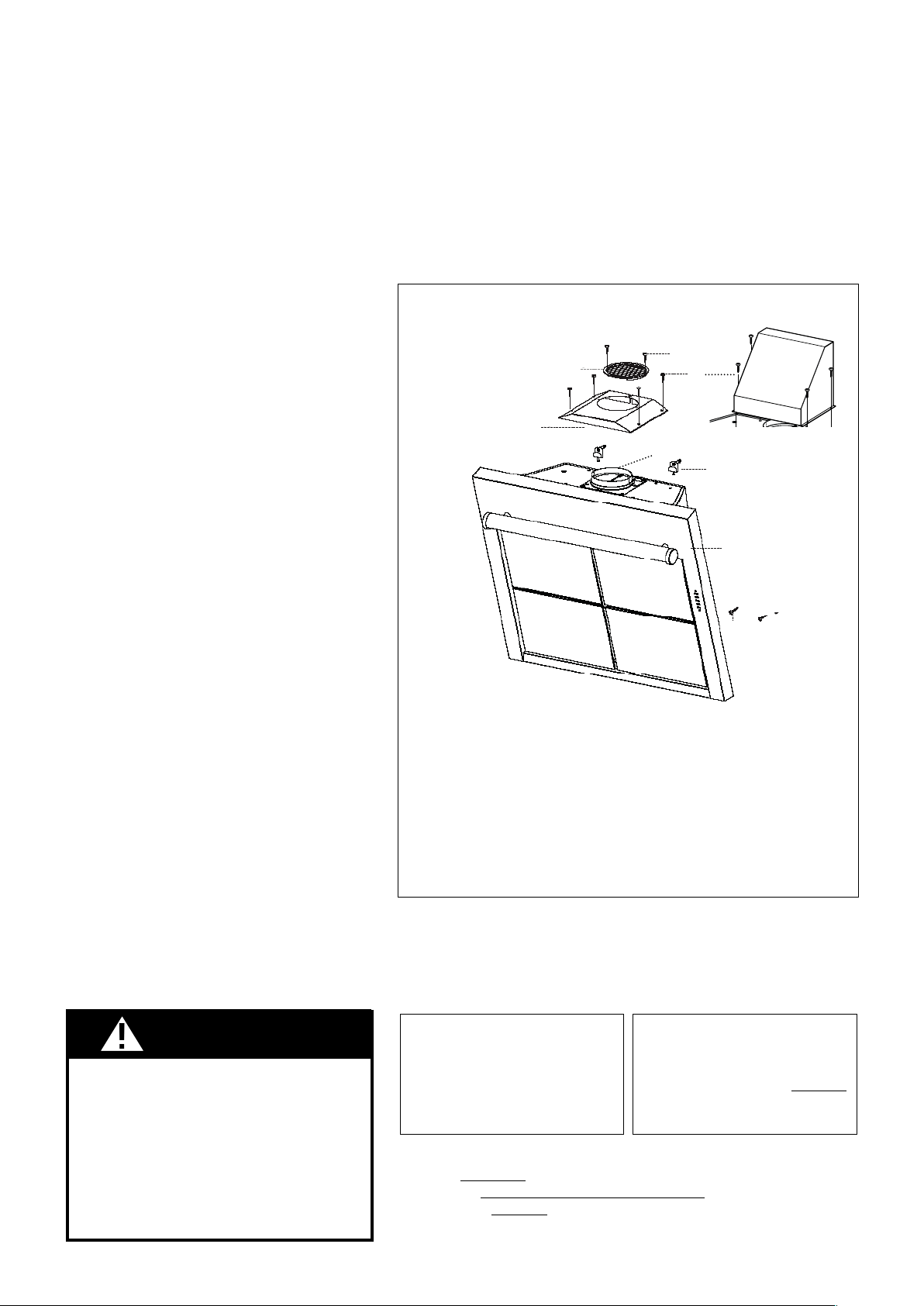
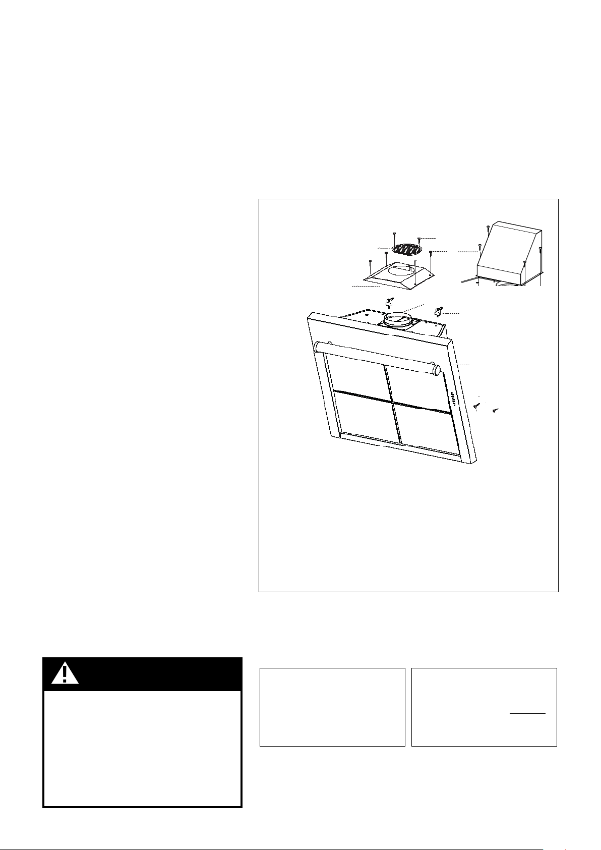
FIGURE 1
A. CANOPY SECTION
B. MOUNTING BRACKETS WITH SCREWS
C. DUCTLESS GRILLE
D. REAR DUCTING CHIMNEY TRANSITION
E. CHIMNEY / VENT SCREWS
F. SAFETY SCREWS
G. GRILLE COVER
H. GRILLE COVER SCREWS
I. DAMPER
!
A
B
C
D
E
F
F
G
H
I
TOOLS NEEDED FOR INSTALLATION
PARTS SUPPLIED FOR INSTALLATION
PARTS NEEDED FOR INSTALLATION
OPTIONAL ACCESSORIES AVAILABLE
Replacement Charcoal Filter
• Optional Chimney Cover
WARNING
CALCULATE THE DUCTRUN LENGTH
FIGURE 2
FIGURE 3
RANGEHOOD COMPONENTS
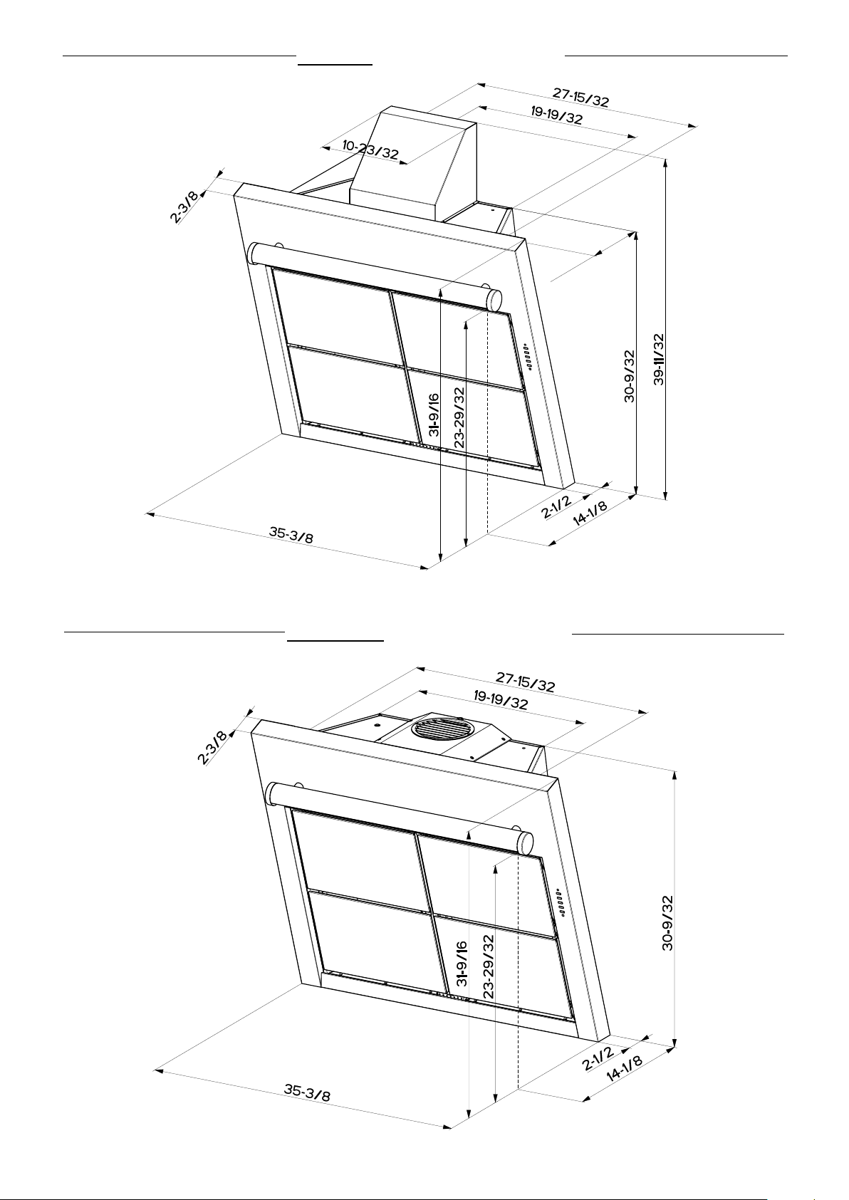
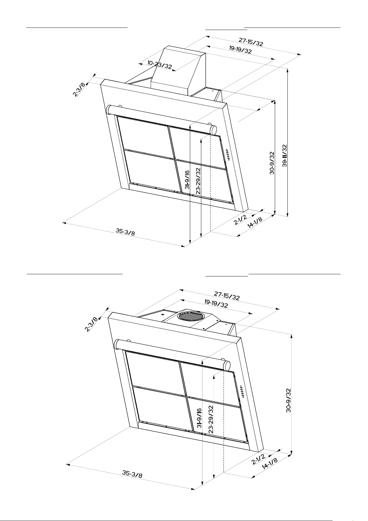
DUCTED INSTALLATION DIMENSIONS
(vented to the outside)
11”
DUCTLESS INSTALLATION DIMENSIONS
(not vented to the outside)
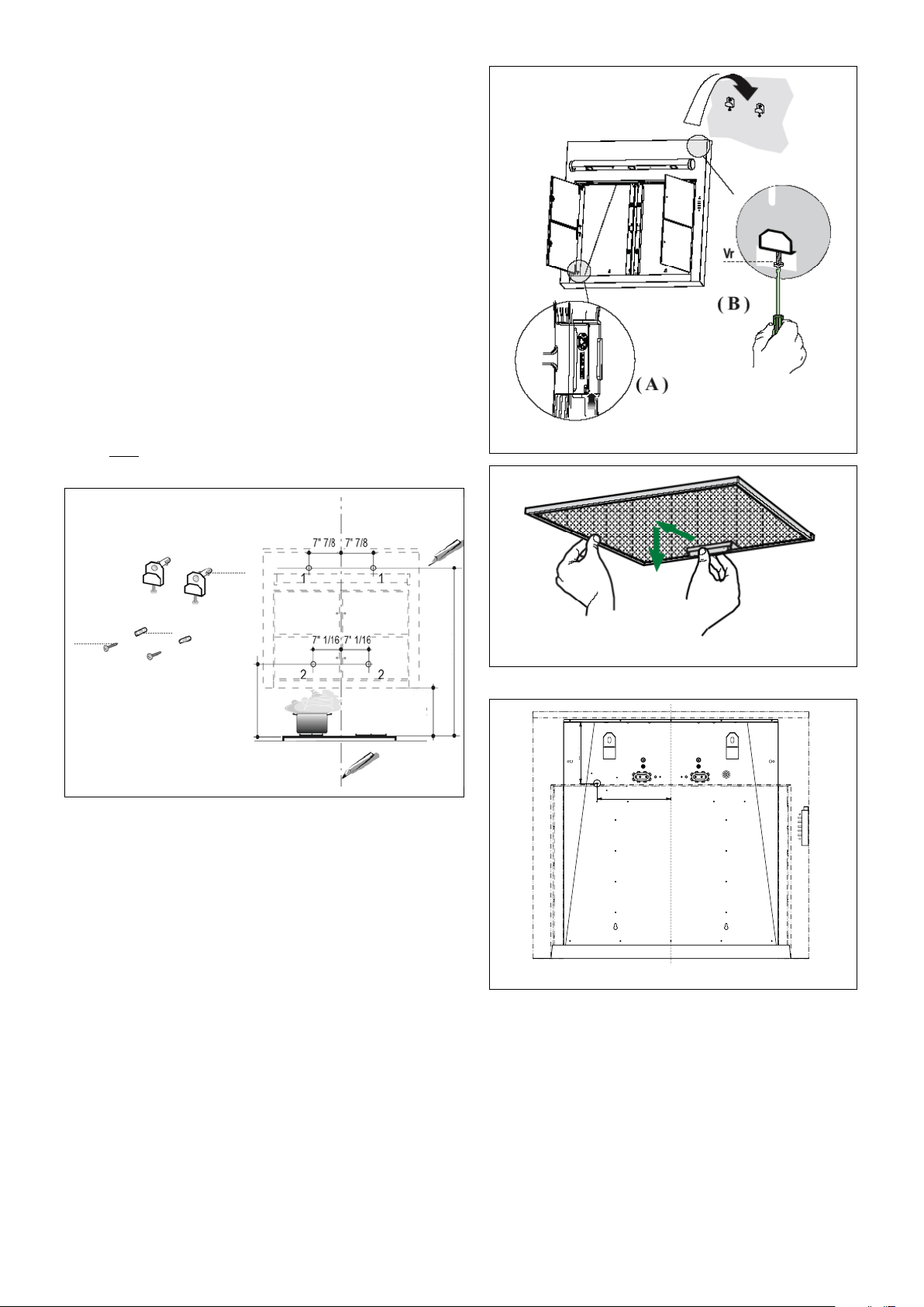
PREPARE THE WALL
1. -
2.
3. (as indicated
in FIGURE 4). (in FIGURE 4)
(in FIGURE 4)
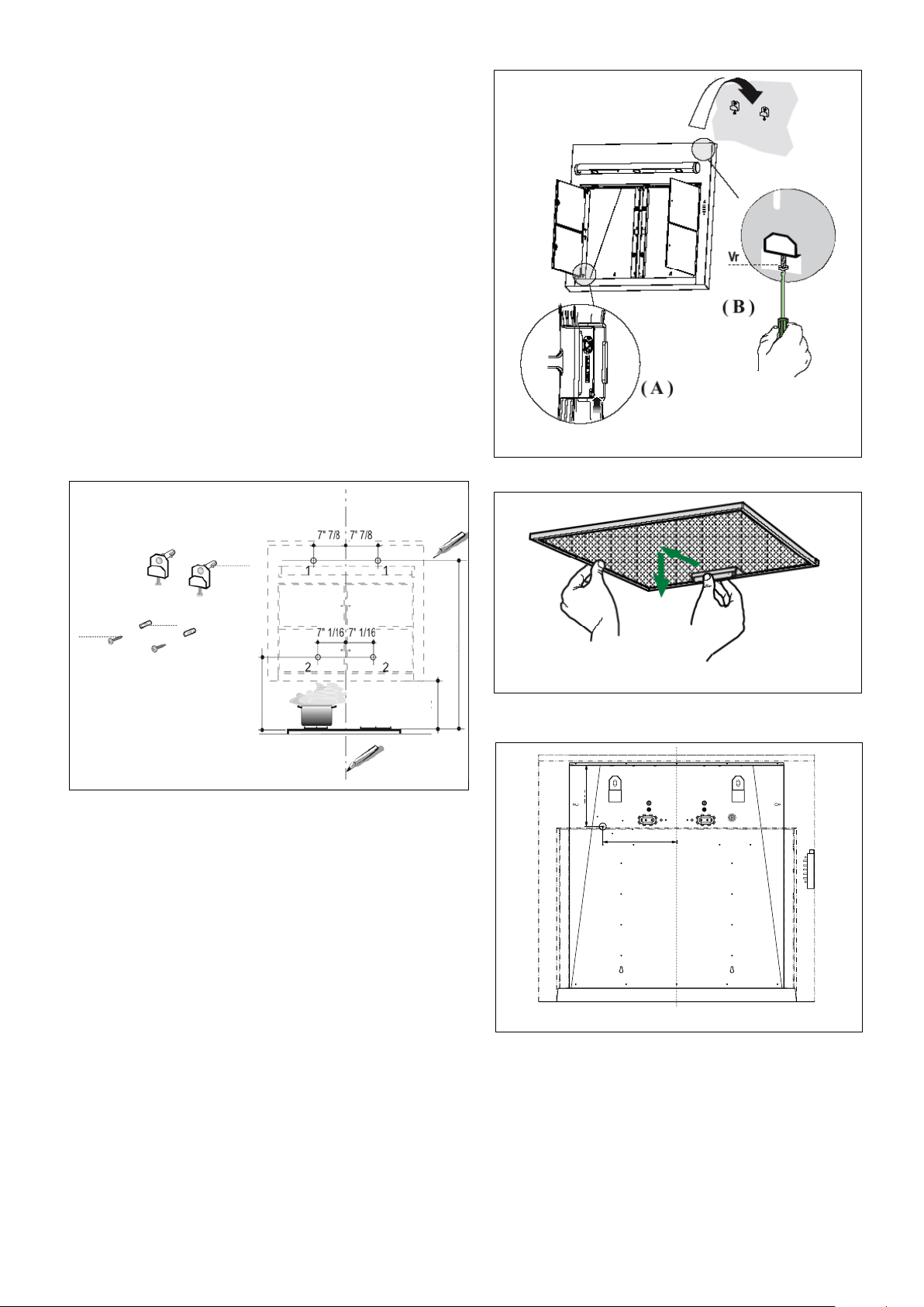
FIGURE 5
5.(in FIGURE 4)
(in FIGURE 4)
B
F
G
FIGURE 4
INSTALL THE RANGEHOOD
1. -
(as indicated in (A)
FIGURE 5).
(FIGURE 6)
(B in
FIGURE 5)
(B in FIGURE 5)
(Hole 2, in FIGURE 4)
6. (I in FIGURE 1) -
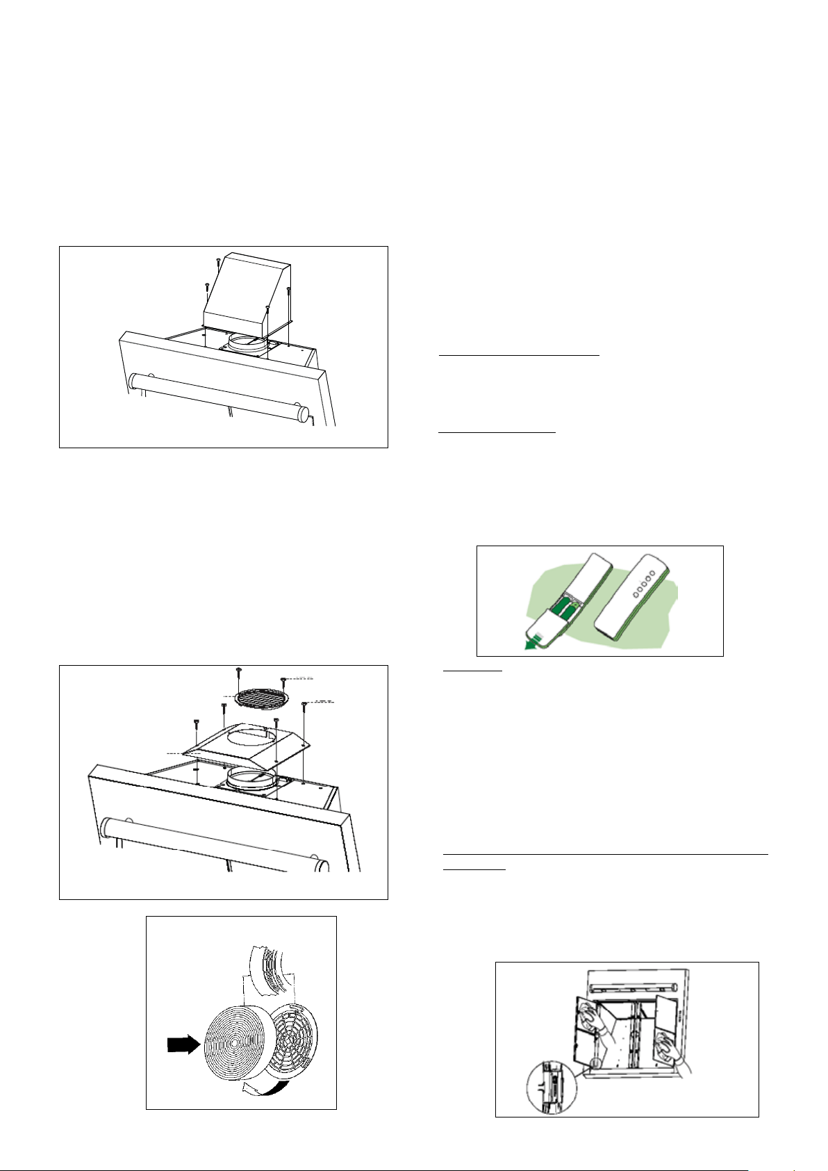
FIGURE 6
FOR ALL INSTALLATIONS
1.
FIGURE
7
WARNING: THE SCREWS PROVIDED FOR MOUNTING THIS
RANGEHOOD MUST BE INSERTED INTO SOLID WOOD. THESE
MUST NOT BE INSERTED INTO SHEET ROCK.
15"
19 7/16"
43"
FIGURE 7
7 7/8"
9 7/16"
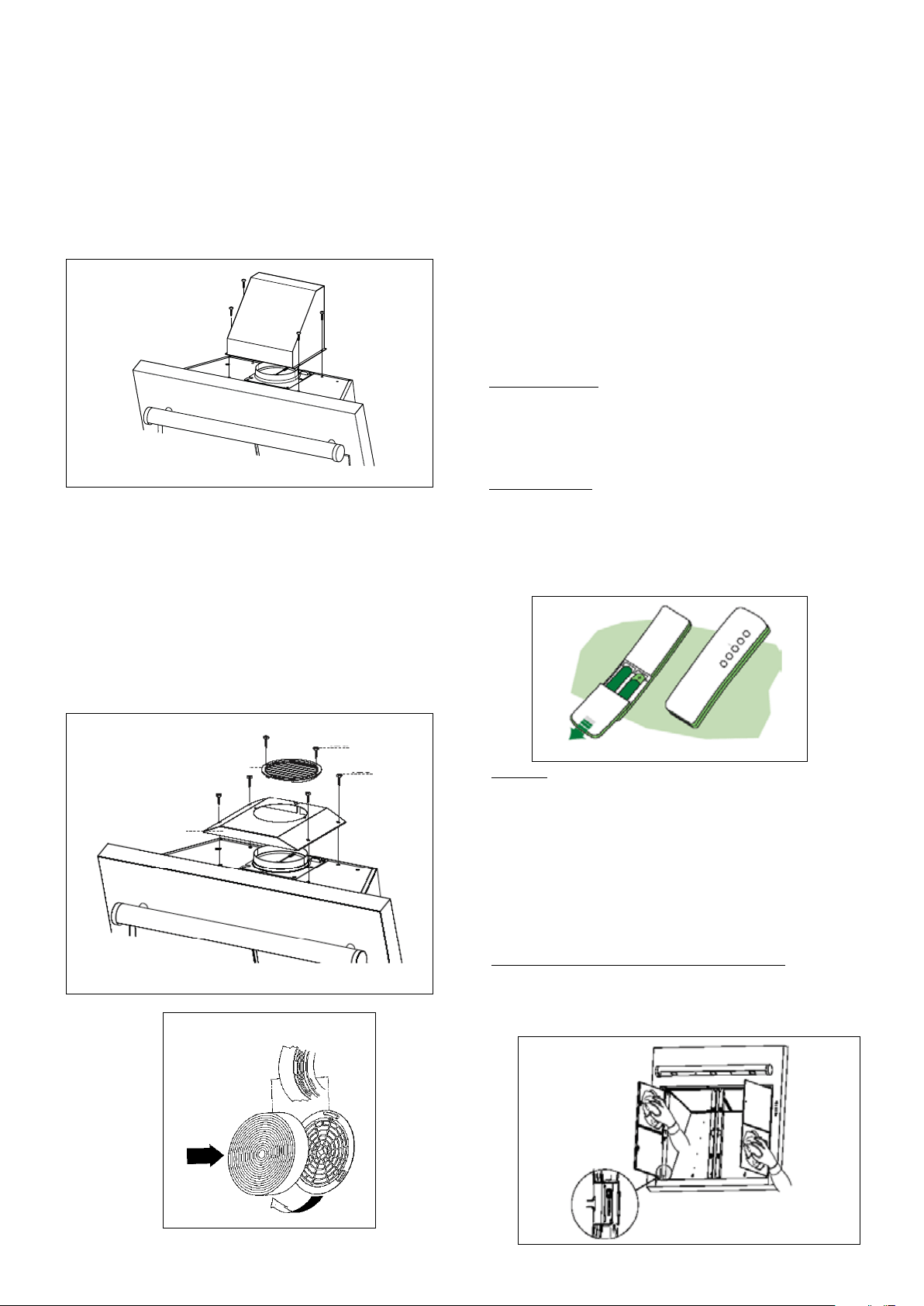
DUCTED INSTALLATIONS
FIGURE 8
1.
(FIGURE 8)
FIGURE 9
C
E
H
I
DUCTLESS INSTALLATIONS
1.
(part C using the E screws in FIGURE 9)
H in FIGURE 9
(I in FIGURE 9).
(as indicated in FIGURE 10).
FOR ALL INSTALLATIONS
1. (as indicated in FIGURE 6)
(as indicated in FIGURE 5)
FIGURE 10
USE AND CARE INFORMATION
For Best Results
Remote Control
(as indicated in
FIGURE 13).
(as indicated in FIGURE 11). Do not
place the remote control close to heat sources.
FIGURE 11
Cleaning
(FIGURE 12)
Grease Filter and Charcoal Filter Alarm Reset
FIGURE 12
Version 12/08 - Page 8
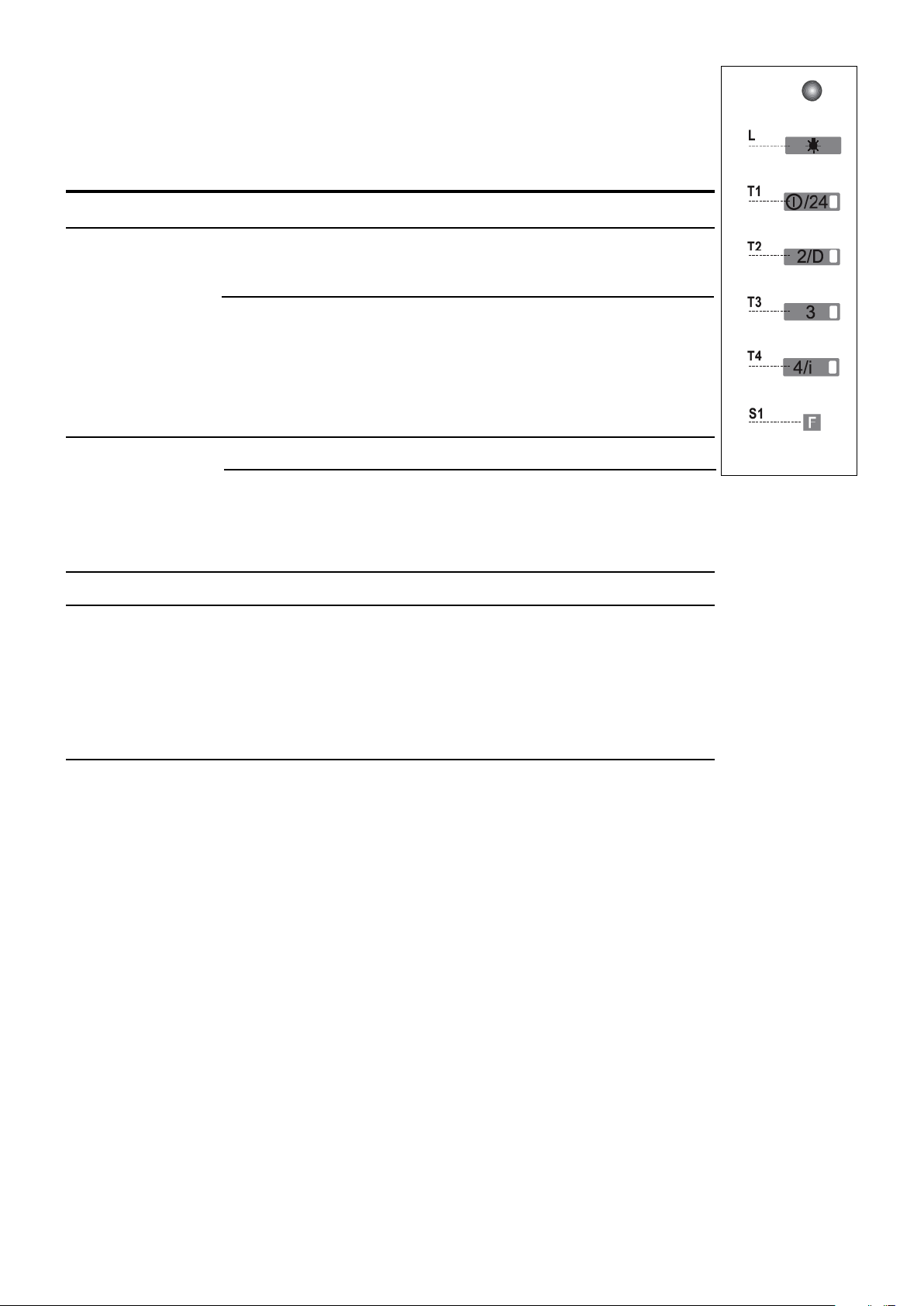
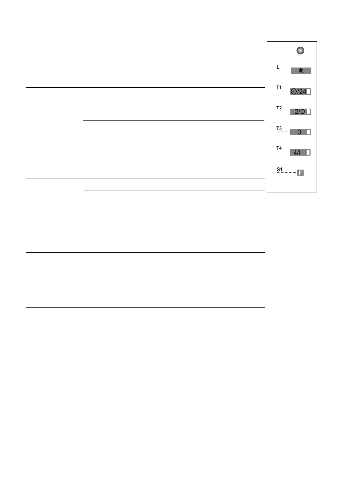
USE AND CARE CONTINUED - CONTROL PANEL
FIGURE 13
First speed (press button)
24 hour function
Second speed (press button)
FUNCTIONS
GREEN LED
KEY
L
T1
T2
T3
T4
S1
ON
ON
ON
ON
ON
30 minute Delay Function
Third speed (press button)
Max. speed (press button)
Intensive Boost Function
USE AND CARE CONTINUED - MAINTENANCE
Charcoal Filter Information
(as indicated in FIGURE
9)
Charcoal Filter Alarm Activation
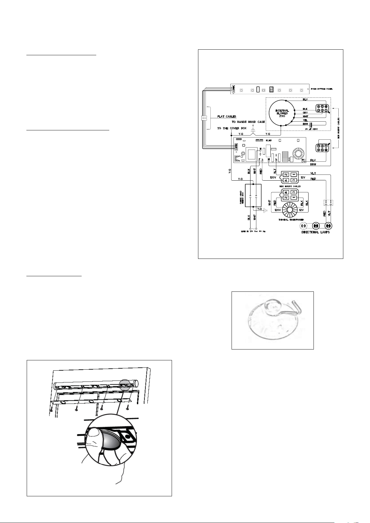
Replacing the Lamps
(as indicated in FIGURE 14)
FIGURE 15
FIGURE 14
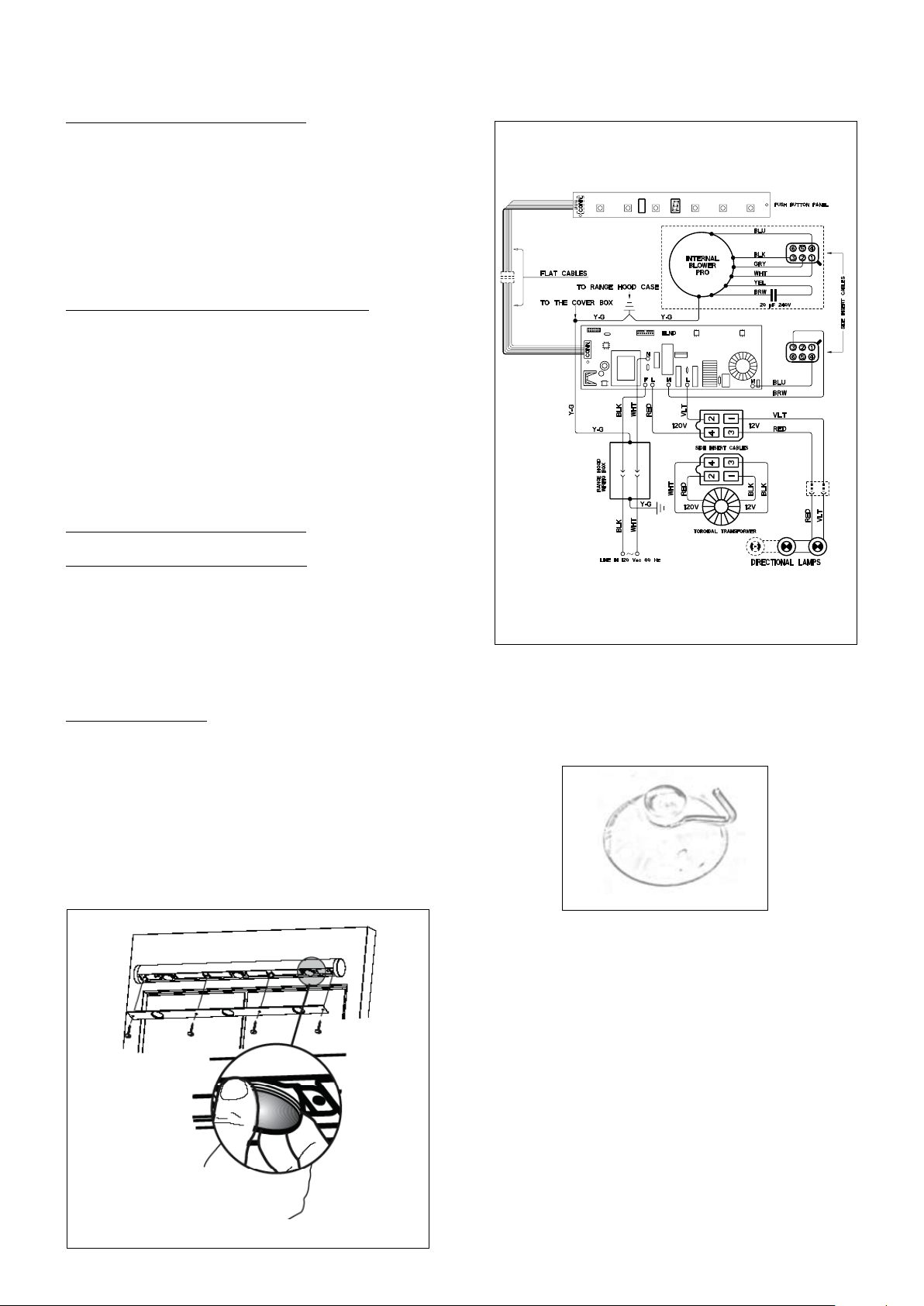
WIRING DIAGRAM
FIGURE 15

Version 12/08 - Page 10
FABER WARRANTY & SERVICE (SAVE FOR YOUR RECORDS)
The Following is not covered by Faber's warranty:
Record Your Information Below:
Serial #: __________________________
Date of Purchase: ______________
Version 12/08 - Page 11
Pour de meilleurs résultats, ne pas utiliser plus de trois coudes de
90
o
. S’assurer qu’il y ait un minimum de 24 po de conduit droit entre
les coudes si l’on utilise plus d’un coude. Ne pas installer deux
coudes ensemble.
FIGURE 3FIGURE 2
PLAN DE L’INSTALLATION
AVERTISSEMENT!
FIGURE 1
A. HOTTE
B. CROCHETS DE MONTAGE AVEC VIS
C. GRILLE POUR INSTALLATION SANS CONDUIT
D. CONDUITE DE TRANSITION ARRIÈRE DE LA
CHEMINÉE
E. CHEMINÉE / VIS POUR CONDUIT
F. VIS DE SÉCURITÉ
G. COUVERCLE DE LA GRILLE
H. VIS POUR COUVERCLE DE LA GRILLE
I. LE REGISTRE
A
B
C
D
E
F
G
M
I
OUTILS NÉCESSAIRES À L’INSTALLATION
PIÈCES FOURNIES POUR L’INSTALLATION
PIÈCES NÉCESSAIRES POUR L’INSTALLATION
ACCESSOIRES POUR L’INSTALLATION
REMPLACEMENT DU FILTRE AU CHARBON
Pour installation sans conduit seulement.
Remplacer le filtre au charbon lorsque
nécessaire (pièce # 6093034)
• COUVERCLE DE LA CHEMINÉE (OPTIONNEL)
Pour installation où la ventilation arrière/
recirculation est impossible ou non désirée.
Lors de ventilation au-dessus, vous pouvez
acheter un couvercle de cheminée en acier
inoxydable pour couvrir le conduit, pièce #
4472020 (cheminée basse) et pièce # 4472013
(cheminée du dessus).
ASSEMBLAGE DE LA HOTTE
CALCUL DE LONGUEUR DU CONDUIT
FIGURE 2
FIGURE 3
AVERTISSEMENT
!
Version 12/08 - Page 12
DIMENSIONS D’INSTALLATION AVEC CONDUIT
11”
DIMENSIONS D’INSTALLATION SANS CONDUIT
PRÉPARATION DU MUR
1.
2.
3.
FIGURE 5
5.
B
F
G
FIGURE 4
NSTALLATION DE LA HOTTE
1.
6.
FIGURE 6
POUR TOUT LES INSTALLATIONS
1.
Schéma 7
Avertissement: Les Vis Fournies Pour Le Montage De Cette
Hotte De Cuisinière Doivent Être Insérées Dans Du Bois
Solide. Elle Ne Doivent Pas Être Insérées Dans Un Mur Ou
Un Plafond De Plâtre.
15"
19 7/16"
43"
FIGURE 7
7 7/8"
9 7/16"
INSTALLATIONS AVEC CONDUIT
FIGURE 8
1.
FIGURE 9
C
E
H
I
INSTALLATION SANS CONDUIT
1.
POUR TOUTES LES INSTALLATIONS
1.
-
FIGURE 10
UTILISATION ET ENTRETIEN
Pour de meilleurs résultats
Contrôle À Distance
FIGURE 11
Nettoyage
Réactivation De L’alarme Du Filtre À Graisse Et Du Filtre
À Charbon
FIGURE 12
PANNEAU DE CONTRÔLE - UTILISATION ET ENTRETIEN (SUITE)
FIGURE 13
Première Vitesse (bouton pressoir)
Fonction 24 Heures
-
Deuxième Vitesse
FONCTIONS
LED VERT
CLEF
L
T1
T2
T3
T4
S1
Mise En Marche Différée De 30 Minutes
-
Troisième Vitesse (bouton poussoir)
Vitesse Maximale (bouton poussoir)
Fonction Intensive
-
-
-
-
ENTRETIEN - UTILISATION ET ENTRETIEN (SUITE)
Informations Sur Le Filtre À Charbon
Activation De L’alarme Des Filtres Au Charbon
Deux Clignotements: Réglage activé
Un Clignotement: Réglage désactivé
Replacer Les Lampes
(de la FIGURE 15)
FIGURE 14
DIAGRAMME DE CÂBLAGE
FIGURE 15

FABER GARANTIE ET SERVICE (
ÉCONOMISER POUR VOS ENREGISTREMENTS
)
Les frais suivants ne sont pas couverts par la garantie Faber :
Enregistrez Votre Information Ci-dessous:
Séquentiel #: __________________________
Date d'achat: ______________