Loading ...
Loading ...
3
The lid switch will affect the LEDs by deactivating any
active LED in the service mode for L3D control when the
lid is raised. This allows the technician to determine if
the switch is working.
Service Mode Error Codes
E1 EEPROM Error
E2 Thermistor Error
E3 Flood Condition Detected Error
E4 Slow Pump Error
E5 Never Fills Error
E6 Pump Detection Circuit Error
E7 Pushbutton Error (shorted pushbutton)
E8 Pressure Switch Error
E9 Serial Communication – L3D Internal
E0 Serial Communication – External
If you are in the Error Codes Function Display and you
press the Start pushbutton, then the control will clear all
errors.
If you are in the Model Code Function Display and you
press the Start/Pause pushbutton, the control will
display the EEPROM Revision contained in the EEPROM
only while the button is depressed.
If you are in the Hot Water Valve Active Display and you
press the Start/Pause pushbutton, the control will
display the ROM Revision of the software only while the
button is depressed.
The service mode will allow the technician to operate
the washer in dry agitate. However, if the washer is
placed in either agitate function during the diagnostics
and the Start pushbutton is pressed for 2 seconds the
dry agitate will become wet agitate. This wet agitate
stops the motor, and energize the cold water valve until
the pressure switch is made. To determine if the pres-
sure switch is working correctly, the control turns on
wash temperature LEDs in sequential order from the
smallest load size LED to the largest load size LED. For
example, the Cold Wash size LED will represent a small
load and the Hot Wash size LED represent a full basket
of water. After the tub has reached the full basket, then
the washer resumes agitation.
When advancing through the service mode functions,
energizing LEDs and the accompanying beeps will occur
immediately. However, a 0.5-second delay will occur
before initiating the new function. The sequence of
events are: the previous function will stop; the LED for
the previous function will deactivate; the LED for the
new function will activate and the beeper will beep; one
(1) second will pass and the new function will begin. This
will allow the technician to hear one function stop and
another start.
L3D Field Service Mode
Entrance/Exit
Diagnostics
The control provides diagnostics to inform the operator
of the current status of the washer. The LEDs displayed
to indicated the fault will flash at a rate of 1 hertz.
Serial Communication Diagnostic Test
To perform the serial communication diagnostic test, the
L3D control will issue a request to the DCR for its soft-
ware version number. Verification of the transmitted
packet data will confirm the serial communication
hardware on the L3D is functional. Alternatively, recep-
tion of a machine status request command from the DCR
will also be considered sufficient to demonstrate func-
tional serial communication hardware. If no status
request is received and there is either no response to
the DCR version number request or the response is
invalid, then an external communication error will be
assumed, generating a E0 error code on the DSSD.
If the external communication test fails, the L3D control
will perform a loop-back test by verifying the transmitted
packet data is also seen upon the RxD pin on the micro-
processor. A failure in the loop-back test indicates a
potential failure on the L3D hardware or a short circuit
on the Data Comm I/O line, yielding an E9 fault.
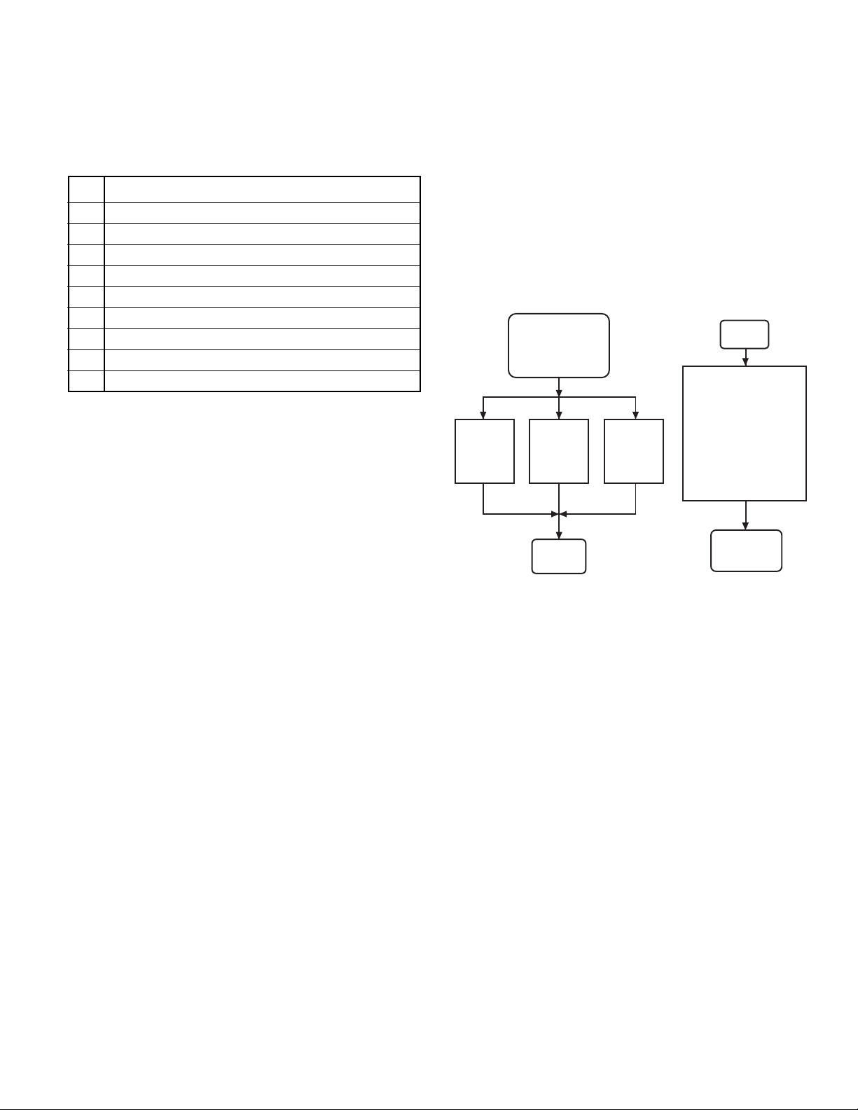
Termination of the Service Mode can be Accomplished
in Three Ways:
1. The user may remove power by unplugging the unit.
2. The control will exit the S1 – Field Service Mode 30
minutes after the beginning of the Mode.
3. Removal of the Service Mode Card
By removing the Service Mode Card, the DCR will
recognize that the service mode is terminated. The DCR
will transmit a Stop command to the L3D control to
return the L3D to the idle state.
Field
Service Mode
Idle
Idle
Removal
of
Service
Card
30 min
time-out
from
start of
mode
Loss of
Power to
Control
Field
Service
Mode
Initiate field Service
Mode by using the
Service Mode card
or simultaneously
pressing and holding
the Start and
the White Cotton
pushbuttons with the
Service Selector
Harness inserted
Loading ...
Loading ...
Loading ...