Loading ...
Remove 4 Screws
CLOTHES CARE SELECTION
TEMPERATURE
W
ASH
/RINSE SPEED
HOT W
A
SH
COLD W
ASH
W
AR
M W
ASH
NO
RMAL/SLOW
G
ENTLE/SLOW
N
ORM
AL/FA
ST
STATUS
START
PERM
P
RES
S
CO
LO
RED
C
OTTO
NS
W
HIT
E
CO
TTO
NS
BRIGHT
CO
LORS
D
ELIC
A
TE
S
W
ASH
RIN
SE
FILL
FIN
AL SP
IN
FIN
ISHED
C
a
r
d
S
L
I
D
E
b
y
E
S
D
E
S
T
T
I
M
E
R
E
M
A
I
N
I
N
G
SmartCard
Reader
Dual Seven
Segment Display (DSSD)
2
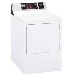
Accessing Components
SmartCard Reader – Removal and Replacement
1. Remove four screws from top panel and pull forward.
Field Service Mode
T
he Field Service Mode for L3D controls allows the field
service technician to test the inputs and outputs of the
control. It also allows the technician to step through the
test cycle and operate components on the washer.
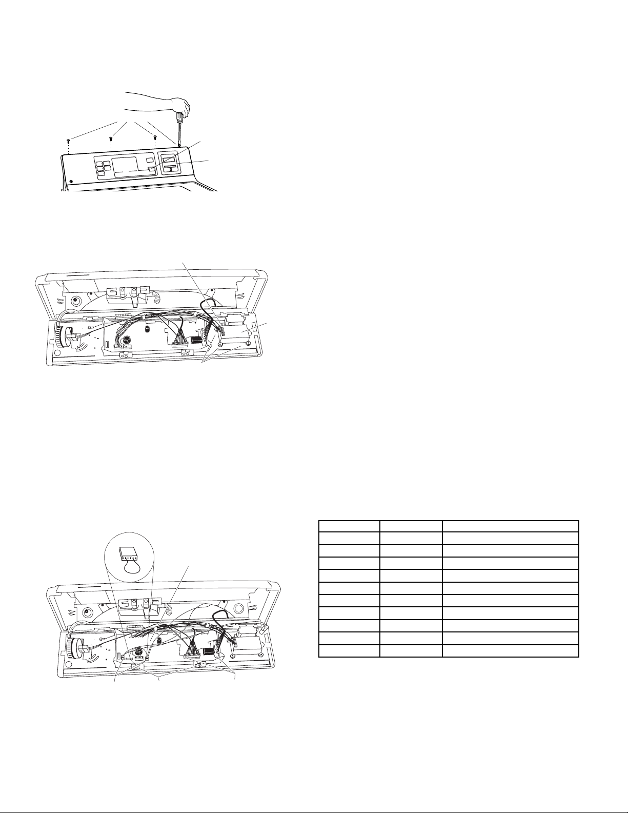
2. Remove the four corner screws from the SmartCard
Reader.
3. Remove connector cable from reader.
4. Reverse the above procedure to reinstall.
Electronic Control Board – Removal and Replacement
1. Follow step 1 above.
2. Remove 4 harness connections. Remove and retain the
model selector harness plug for reassembly.
3. Remove 2 screws (1/4-in) from the control board.
CAUTION: To prevent electrostatic discharge, ground
yourself to the washer cabinet or use an ESD wristband.
4. Remove the electronic control board.
Note: When reassembling, align the LEDs with the
appropriate control panel indicators.
5. Reverse the above procedure to reinstall.
SmartCard
Reader
Remove 4 Screws
Connector Cable
This feature holds true for all tests with exception of the
serial communication test. The serial communication test
can be run only once due to the limited time required to
run the test. Once the serial communication test has
been run, the operator must exit and reenter the mode to
repeat the test.
* ➔ Indicates model number
# ➔ Indicates number of error code if there is more than
one error, each error will display for 2 seconds, followed
by the next error)
The Field Service Mode can be entered manually or by
inserting a special Service Mode card (available to commer-
cial laundry owners) into the SmartCard reader.
Manual entry into the Field Service mode requires the Model
Selector harness WD21X10026, to be installed into the L3D
control. This is the Service Selector harness. To install the
Service Selector harness, disconnect power to the machine
and remove the currently installed Model Selector harness.
Save the removed Model Selector harness for reinstallation
after service. Install the Service Selector harness into the
control board and reconnect power to the machine. Note:
When the service operation is completed, remove the
Service Selector harness and reinstall the previous Model
Selector harness.
After reconnecting power, the L3D control test cycle is
entered by pressing and holding the White Cotton and the
Start button simultaneously for 3 seconds. As soon as the
test cycle is entered, the control will power the Dual Seven
Segment Display (DSSD) to output the letters Fd (Field
Service Diagnostics).
Manual entrance into Field Service mode will be restricted to
the time period of 15 seconds after Power-On-Reset of the
L3D electronic control. Following this time, the key sequence
method of entry into the service mode will be disabled.
The service mode may also be entered by receiving the
appropriate command via the serial communication port
using the Service Mode Card. Entry into the Field service
mode will be allowed at any time the machine is powered
and in the idle state.
When any of the above buttons are pressed or when the
pressure switch is pushed or contacted, the control will beep
for 0.5 seconds.
The initial step after entering service mode for the L3D
electronic control will be defined as Step 0. This will
signal the DSSD to output Fd and the control will light all
LEDs. The following table gives required functions for
subsequent steps. To proceed to the next step, press the
Color Cottons pushbutton. To return to the previous position,
press the White Cottons.
DSSD
Position Output Function
0-Initial Fd LED Check
1 ** Model Code
2 E# Error Codes
3 H Hot Water Valve Active
4 C Cold Water Valve Active
5 AL Slow Agitate (Dry)
6 AH Fast Agitate (Dry)
7 P Pump
8 SP Spin
Remove Harness
Connections (2)
Remove Harness
Connections (2)
Screws
(2)
Electronic
Control Board
Model Selector/
Service Selector
Harness
Loading ...
Loading ...
Loading ...