Owner's Guide Water Heater
ANODE
The water heater is fitted with a sacrificial anode to extend it’s life. It will slowly dissipate whilst protecting the cylinder. The life of the water heater may be extended by arranging for an authorised person to inspect the anode and replace it if required. It is recommended that the anode be inspected at least every 5 years. The factory fitted Rinnai anode is Magnesium based. This anode is suitable when the total dissolved solids (TDS) content in the water supply does not exceed 600 mg/L, which is the case in most areas. In areas where the total dissolved solids (TDS) content in the water supply exceeds 600 mg/L the Rinnai aluminium based anode is required.
WATER QUALITY
The water quality of most public supplies is suitable for the water heating system. The water quality from bore wells is generally unsuitable for the water heating system. Refer to the ‘Warranty Conditions’ for water quality parameters and how they affect the warranty conditions. If in doubt about the water quality, have it checked against the parameters listed in the warranty conditions. If sludge or foreign matter is present in the water supply, a suitable strainer filter should be incorporated in the water supply to the system.
OPERATIONAL OVERVIEW (How the hot water system works)
Single Element Model: A vitreous enamel lined steel cylinder stores water which is heated by a single thermostatically controlled heating element, located at the base of the cylinder. The water heater connects directly to the mains water supply. The heating element can be connected to a Continuous or Off‑Peak electricity supply. The continuous supply is appropriate when the water heater capacity is less than the daily usage of hot water. The Off‑Peak supply is appropriate when the water heater capacity exceeds the daily usage of hot water. The Off‑Peak supply allows heating only for set periods and a volume of water sufficient for daily usage is heated during the set period and stored. The Off‑Peak supply is usually cheaper. Electricity supply types and tariffs vary according to the local electricity authority
Twin Element Model: A vitreous enamel lined steel cylinder stores water which is heated by a twin thermostatically controlled heating elements, one element is located at the base of the cylinder, while the other is located near the top. The water heater connects directly to the mains water supply. The bottom heating element heats the whole contents of cylinder and Top heating element (booster) only operates during the high demand periods to heat the upper portion of the contents of the cylinder. The two heating elements are wired for non-simultaneous operation, so that only one heating element can operate at a time. The bottom heating element can be connected to an Off‑Peak electricity supply, and the top heating element to a continuous electricity supply.
Turning Water Heating System ‘OFF’
If the water heater is not going to be used for only a few days, we suggest you leave it switched on. If it is necessary to switch off the water heater, the switch is usually marked and located in the electricity meter box of the building.
Turning Water Heating System ‘ON’
Switch on the electric supply to the heating elements. The switch is usually marked and located in the electricity meter box of the building. Water heating will now occur as required. It may take a number of hours before hot water is available.
DRAINING
WARNING
- Draining MUST BE carried out by a qualified person.
- Water may be HOT during draining.
Drain the water heater as follows:
- Isolate or turn ‘OFF’ the water heater at the electricity supply
- Close the cold water isolation valve at the inlet to the water heater
- Close all hot water taps
- Operate the PTR valve easing gear - gently.
Operating the PTR valve easing gear will relieve the pressure in the water heater
- Undo the cold water inlet union.
Attach a hose to the water heater side of the union.
Let the other end of the hose go to a drain
- Operate the PTR valve easing gear again. This allows air into the water heater and will result in water draining through the hose.
SPECIFICATIONS
APPLIANCE COMPONENTS
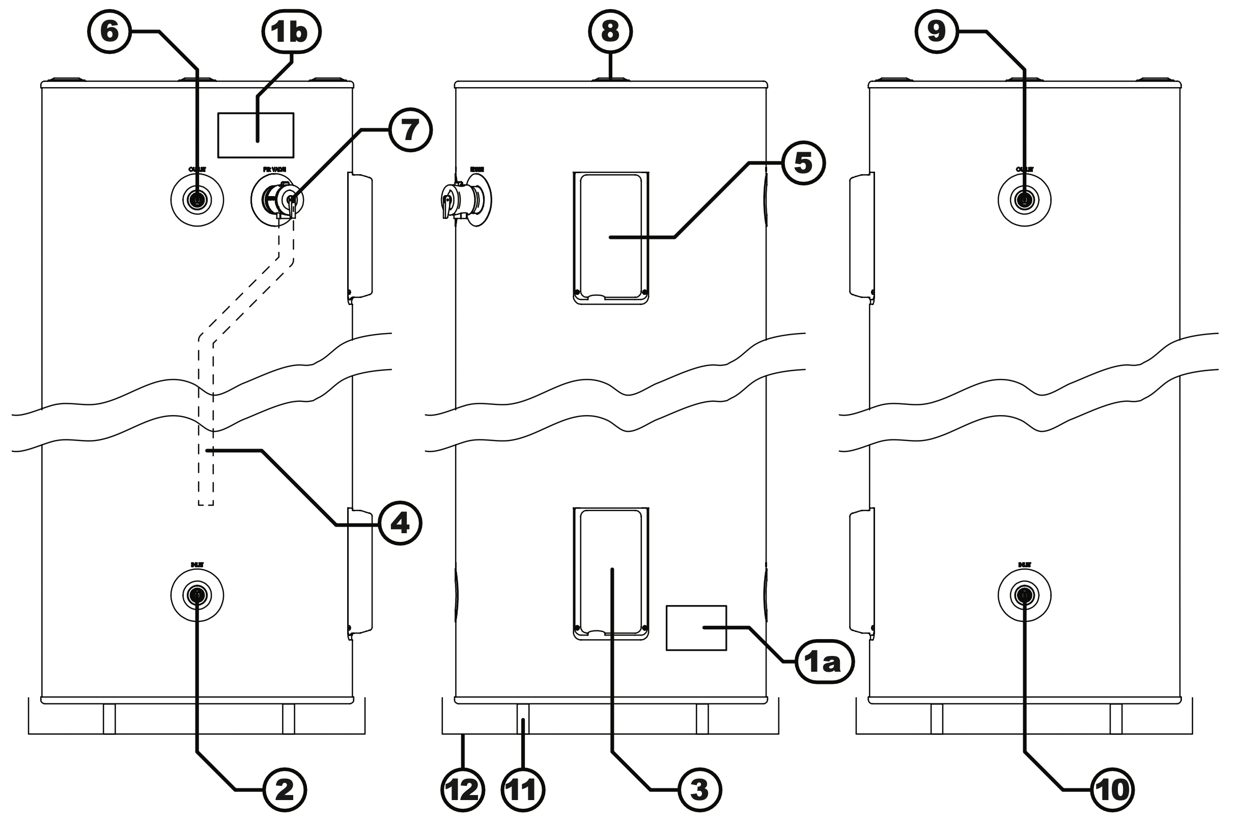
- Data / Warning labels
- Left hand cold water inlet
Connection RP 3/4" (20mm)
- Element / thermostat / electrical supply connection cover
- PTR valve drain pipe
Copper only drain in accordance with AS/NZS 3500.4
- Element / thermostat cover (Twin element models only) *
- Left hand hot water outlet
Connection RP 3/4" (20mm), use a union connection and insulate hot water pipe
- PTR valve connection
RP 1/2" (15mm), use supplied PTR Valve
- Anode cap
- Right hand (duplicate) hot water outlet
Connection RP 3/4" (20mm), use a union connection and insulate hot water pipe
- Right hand (duplicate) cold water inlet
- Water heater support
In accordance with AS/NZS 3500.4
- Safe Tray & drain
Where required, in accordance with AS/NZS 3500.4
NOTE: * Remove and connection by qualified persons ONLY, in accordance with AS/NZS 3000.
Valves with pressure ratings other than specified are unsuitable and MUST NOT be used.
WATER HEATER - located closet to most frequently used outlet - Access for service in the installation position.
INSTALLATION
This appliance MUST BE installed by a qualified person in accordance with:
- Manufacturers installation instructions
- Current AS/NZS 3000 Wiring Rules
- Current AS/NZS 3500.4 Plumbing and Drainage - Heated Water Services
- All local regulatory requirements
This appliance is NOT suitable for use as a spa or swimming pool heater.
LOCATION
The Rinnai Hotflo (EHFA/EHFD) storage water heater range have an ingress protection rating of IPX4 making them suitable for internal or external installation.
The water heater should be placed as close as practicable to the most frequently used hot water outlet point or points to minimize the delay time for hot water delivery. This will usually be the kitchen tap. For installations where the distance between the water heater and the outlets is considerable, a flow and return system can be used which will minimize the waiting time for hot water delivery.
It is recommended that the water heater is installed at ground or floor level. It MUST� BE installed in a vertically upright position. The water heater MUST BE accessible without the use of a ladder or scaffold. Installation into roof spaces MUST comply with local regulatory authority requirements.
Ensure the PTR valve, isolating valves, access covers, thermostats and heating elements have sufficient clearances and are accessible for service and removal. The information on the rating plates MUST also be readable.
The water heater MUST BE installed in free standing mode on a level and stable base in a manner that is acceptable to local authorities. Avoid situations that may result in pooling of water around the base of the water heater.
Where property damage can occur as a result of water leakage, the water heater MUST BE installed with a safe tray (overflow tray) and drain. Construction, installation and draining of the safe tray MUST comply with local regulatory requirements and AS/NZS 3500.4 also requires the use of a safe tray for particular situations.
WATER QUALITY
The water quality of most public supplies is suitable for the water heater. Water quality from bore wells is generally unsuitable. Refer to the ‘Warranty Conditions’ for water quality parameters and how they affect warranty. If in doubt about water quality, have it checked against the parameters listed in the warranty conditions.
If sludge or foreign matter is present in the water supply, a suitable strainer or filter should be incorporated in the water supply to the water heater.
Scaling water is defined as having a total hardness in excess of 200 mg/litre (expressed as calcium carbonate) or a Saturation Index in excess of +0.4. Areas that have a scaling water supply include South Australia and Western Australia. In a scaling water supply, calcium carbonate and possibly other compounds are deposited out of the water onto any hot metallic surfaces and form a scale.
In areas of scaling water an ECV MUST BE fitted on the cold water line between the non‑return valve and the connection to the water heater to protect the PTR valve and the water heater. Local regulatory authorities may require that an ECV be fitted. The ECV is to be supplied and fitted by the installer.
MAINS PRESSURE
The Hotflo (EHFA/EHFD) electric storage water heater range utilise mains pressure by connecting directly to the mains water supply. If the mains water supply pressure in your area exceeds the rated pressure of the water heater a PLV MUST BE fitted.
The mains water supply pressure should be greater than 350kPa for true mains pressure operational performance to be achieved.
THERMOSTAT SETTING
The thermostat setting can be adjusted between 60°C and 70°C. It has been factory pre-set to 70°C.
WARNING: The thermostat settings MUST ONLY be adjusted by a qualified person.
REDUCING THE RISK OF SCALDING
This water heater can deliver water at temperatures which can cause scalding. Children, disabled and the elderly are at the highest risk or being scalded.
Local regulatory requirements and the requirements of AS/NZS 3500.4 MUST BE considered regarding temperature limitations of hot water delivered to areas used primarily for personal hygiene such as bathrooms and ensuites. The delivery temperature may be limited to 45°C for early childhood centres, primary and secondary schools and nursing homes or similar facilities for the young, aged, sick or people with disabilities and 50°C for all other buildings. These temperatures will reduce the risk of scald injury and can be achieved by the use of a TLD, for example a thermostatic mixing valve or tempering valve.
Rinnai recommend that an approved TLD is fitted into the hot water pipe work from the water heater to areas used primarily for personal hygiene such as bathrooms and ensuites to reduce the risk of scalding. Refer to the installation configurations "Hot Water Plumbing System Example ‑ With TLD" on page 12 and "Hot Water Plumbing System Example / Flow & Return Pipe Work ‑ With TLD" on page 13.
PLUMBING CONNECTIONS
Connections to the water heater
Refer to Specifications for the plumbing connection sizes and location (Table 1) and the specified pressure ratings of valves (Table 2). Refer also to the diagrams under “Installation Configurations”.
WARNING: Valves with pressure ratings other than specified MUST NOT be used.
An isolation valve and non-return valve MUST BE fitted in the cold water supply to the water heater so the water heater can be isolated. Combination isolation and non-return valve such as 'Duo' or 'Trio' valves are suitable for this purpose.
Isolation valves MUST NOT be fitted directly to the appliance. Use disconnection unions between the water heater and the valves to allow the water heater to be disconnected from pipework at a later date.
Purge pipework to remove swarf and other foreign matter before final connection to the water heater to avoid damage to the water heater. If olive compression fittings are used for connections the olives MUST BE metallic such as brass or copper. Only approved thread sealing tape or sealant should be used.
Water Pipes
Pipe sizing should be carried out by persons competent to do so for each individual installation in accordance with local regulatory requirements and take into consideration the specifications of the water heater.
The cold supply pipe to and hot water pipe from the water heater MUST BE insulated in accordance with local regulatory requirements and AS/NZS 3500.4 to optimise performance and energy efficiency. Insulation MUST BE weatherproof and UV resistant if exposed.
The hot water pipe from the outlet of the water heater should also be configured in the shape of a “heat trap” to aid energy efficiency in accordance with local regulatory requirements and AS/NZS3500.4.
To prevent damage to the water heater when attaching pipe clips or saddles to the jacket, it is recommended that self drilling screws with a maximum length of 12mm are used. If drilling is required take extreme care NOT to penetrate the inner cylinder. Damage to the inner cylinder is NOT covered under warranty.
Pressure and Temperature Relief (PTR) Valve
A combination PTR valve is supplied with the water heater. It is an important safety device and MUST�BE fitted in all installations before the water heater is operated.
DO NOT use the valve if the sensing probe has been bent or it is damaged in some other way.
The PTR valve is to be screwed to the connection marked “PTR Valve” at the top of the water heater.
The thread MUST BE sealed with an approved sealing tape. Make sure the sealing tape does NOT hang over the end of the thread of the valve as this may block the waterway and prevent the valve from operating properly.
To screw the valve into the water heater connection use a wrench on the spanner flats and NOT the valve body. Leave the valve outlet pointing downwards. A copper drain pipe MUST BE fitted to the valve outlet in accordance with the section "Relief Valve Drain Lines" on the bottom of page 16.
The valve body MUST BE insulated in accordance with local regulatory requirements and AS/NZS 3500.4 to optimise performance and energy efficiency. Insulation MUST BE applied in a manner that ensures it does NOT interfere with the operation of the valve. Insulation material MUST BE weatherproof and UV resistant if exposed.
Expansion Control Valve (ECV)
In areas of scaling water an ECV MUST BE fitted on the cold water line between the non‑return valve and the connection to the water heater to protect the PTR valve and the water heater, as per the diagrams under “Installation Configurations”. It MUST BE the last valve on the cold inlet before the water heater.
Local regulatory authorities may require that an ECV be fitted. The ECV is to be supplied and fitted by the installer.
Refer to the section Water Quality for more information on scaling water.
A copper drain pipe MUST BE fitted to the valve outlet in accordance with the section "Relief Valve Drain Lines" on the bottom of page 16.
The valve body MUST BE insulated in accordance with local regulatory requirements and AS/NZS 3500.4 to optimise performance and energy efficiency. Insulation MUST BE applied in a manner that ensures it does NOT interfere with the operation of the valve. Insulation material MUST BE weatherproof and UV resistant if exposed.
Pressure Limiting Valve (PLV)
A PLV is to be fitted if the supply pressure exceeds the limits shown in Table 2 “Ratings & Other Specifications" on page 11 as per the diagrams under “Installation Configurations”. The PLV is to be supplied and fitted by the installer.
Relief Valve Drain Lines
Copper drain lines of size DN15 MUST BE fitted to the ECV (if fitted) and the PTR valve. Use disconnection unions to connect drain lines to the valves.
The configuration of drain lines MUST BE in accordance with local regulatory requirements and the requirements of AS/NZS3500.4.
The length should be as short as possible on a continuous downward slope with no restrictions. Length should NOT exceed 9 metres with no more than three 45° bends. If a drain line discharges into a tundish, the drain line from the tundish MUST NOT be less than DN20.The drain line from a tundish MUST meet the same requirements as drain lines from relief valves.
The drain lines from the PTR valve and ECV (if fitted) from an individual water heater may be interconnected subject to local regulatory authority requirements and AS/NZS3500.4. The termination point MUST also comply with local regulatory requirements and AS/NZS3500.4. Drain lines MUST NOT discharge into a safe tray.
The outlet of drain lines MUST NOT be obstructed and be positioned so that they are readily discernible but NOT cause injury, damage or nuisance.
In areas where water pipes are prone to freezing, drain lines MUST BE insulated and NOT exceed 300mm in length. In this case the drain line MUST discharge into a tundish through an air gap of between 75mm and 150 mm.
WARNING- HAZARDOUS VOLTAGE. Risk of Electrical Shock: Isolate all sources of supply prior to servicing.
ELECTRICAL SUPPLY
WARNING
- Must be installed, maintained and removed by authorised persons in accordance with AS/NZS3000 and all other relevant local regulations and municipal building codes including OH&S requirements.
- Ensure electric wiring is installed properly. Improper installation may cause malfunction, fire, or electric shock.
- The unit must be earthed following local electrical codes.
A water heater NOT fitted with a power cord & plug MUST have the heating element connected to an independent, fused, AC 240V 50 Hz power supply with an isolating switch installed at the switch board, which shall effectively isolate all active supply conductors from the circuit and means for disconnection must be incorporated in the fixed wiring in accordance with the wiring rules.
Ensure the premises wiring to the system is capable of withstanding the system electrical load (refer to Specifications-Table 1 for electrical load details).
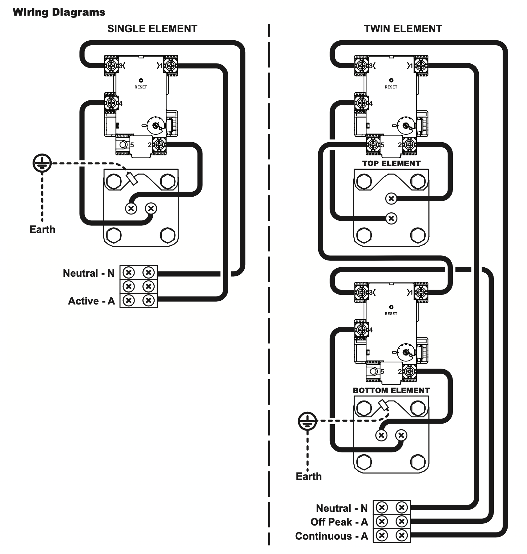
The power supply to a single element model can be Off-Peak (overnight), Extended Off-Peak (overnight and day), or Continuous (day).
The power supply to a twin element model should be Off-Peak (over night) to bottom heating element and Continuous to the top heating element.
Check the available tariffs with the local electricity supplier. The Off-Peak (overnight) is usually the most economical for the customer.
Electrical Connections
WARNING: The water heater MUST BE filled with water prior to connection to the power supply.
WARNING:
- Electrical connection MUST BE carried out by a qualified person and in accordance with AS/NZS3000 'Wiring Rules' and local authority requirements
- Disconnect all power prior to installation and commissioning. This appliance is designed for single phase 240 Volts,AC mains electrical operation.
- All electrical connections MUST BE made by an authorised person and must comply with all local electrical supply regulations and AS/NZS 3000.
NOTE: The premises wiring to the heater must be capable of withstanding the appliance load.
Electrical access is via a 20 mm hole beneath the element cover for mounting with an approved weather proof electrical conduit nipple. For entry to the element cover remove the two fixing screws.
Connect all ACTIVE and NEUTRAL wires in accordance with the wiring diagram which is also included at the rear of the element access cover. Ensure the incoming EARTH wire is securely fixed to the earth post provided on the heater case. Inspect and ensure that all wiring links are secure prior to fixing the access cover and turning the POWER ON.
To ensure the Over-temperature and Energy Cut-out is set, press the (red) 'reset' button on the Thermostat.
Thermostat Setting
The thermostat is adjustable from 60°C to 70°C. Turning the adjustment knob anticlockwise decreases the temperature setting and turning it clockwise increases the temperature setting. The water heater as delivered will have the thermostat preset to 70°C.
WARNING:
- Ensure the power supply is switched OFF before removing the access cover to the element and thermostat.
- The access cover to the element and thermostat MUST ONLY BE removed by an Electrician or other suitably qualified trades person.
- The thermostat setting MUST ONLY BE adjusted by an electrician or other suitably qualified trades person.
- After adjustment, press the (red) 'Reset' Button on the thermostats to ensure the over-temperature and energy cut-out is set.
CARE & MAINTENANCE
SAVE A SERVICE CALL
Check the items below before requesting a service. Service and parts charges may be incurred where it is found that there is no fault with the water heater and the issue is related to the plumbing installation or is due to the failure of water or electric supplies.
|
Insufficient or no hot water
|
|
Is the electricity supply connected?
|
Check that the isolating switch marked “HOT WATER” or “WATER HEATER” at the meter box is switched on.
Check also that any isolating switches installed near the water heater are switched on.
|
|
Check the fuse or circuit breaker marked “HOT WATER” or “WATER HEATER” at the meter box.
Repeated failure of fuse or tripping of circuit breaker indicates a fault which must be investigated by an authorised trades person.
|
|
Is your unit a Twin Element electric water heater?
|
A twin element model (non-simultaneous) must have a continuous electricity supply to the top heating element.
Check that this is the case.
|
|
Are you using more hot water than you think?
|
Often it is not realized how much hot water is actually used.
This applies especially to showering
Review hot water usage, especially the time taken for showering, and investigate the use of flow control valves or Water saving shower roses.
|
|
Are water heater valves discharging excessively?
|
Refer to the section “Safety Devices” on page 7.
|
|
Thermostat settings?
|
Check the temperature of hot water delivered with a thermometer placed under the closest outlet (usually thekitchen sink) on a non-tempered hot water line.
This test should be done early in the morning after overnight electrical boosting before any hot water is used. The temperature of the water delivered should be at least 55°C (allowing for heat losses in pipe work).
If this is not the case, the temperature may need to be increased. Contact your installer or Rinnai to discuss adjusting the thermostat.
|
|
No water from the hot tap?
|
Restriction in the hot tap or failure of the cold water supply to the heater.
Check for water flow at the other hot taps and that the cold water isolation valve is fully open
|
|
High Electricity Bills
|
|
If you think your electricity bill is too high, check for these possibilities.
If, after investigating, and you still require assistance contact Rinnai.
|
You may be using more hot water than you think. This applies especially to showering. Review hot water usage, especially the time taken for showering, and investigate the use of flow control valves or ‘water saving’ shower roses. Investigate recent changes to hot water usage patterns.
|
|
Water heater valves may be discharging excessively. Refer to the section “Safety Devices” on page 7.
|
|
There may be hot water leakages in hot water pipes or taps. Have these checked and rectified by a plumber.
|
|
There may have been changes in electricity tariffs since your last bill.
|
PERIODIC MAINTENANCE & SERVICING
If overflow tray and drain are fitted, it is the users responsibility to have these checked periodically to ensure there are no blockages. The user should operate the easing gear of the ECV and PTR valve (if fitted) every 6 months as described under “Safety Devices” on page 7. Rinnai service network personnel are fully trained and equipped. If your Rinnai appliance requires servicing contact Rinnai as per the details on the back page of this manual. Rinnai recommends that this commercial appliance be inspected and serviced by a qualified person every 12 months.
The ECV and PTR valve MUST BE checked for performance or replaced by a qualified person at intervals not exceeding 5 years or more frequently in areas where the water is classified as scaling water. Refer to both the “Anode” and “Water Quality” on page 8 for Anode selection, inspection and maintenance requirements). If the electric supply conduit to the water heater is damaged, it MUST BE replaced by a qualified person in order to avoid a hazard.
COMMISSIONING
WARNING:
- Commissioning activities MUST BE carried out by an authorised person.
- DO NOT switch on the electric power supply until the water heater is filled completely with water.
TO FILL & TURN ‘ON’ THE WATER HEATER
- Open all hot water taps in the building, including the shower
- Open the cold water isolation valve to water heater
- Air will now be forced out of the taps
- Close each tap when water runs freely without air bubbles
- Check all plumbing connections and pipe work for water leaks
- Connect the water heater to the electricity supply, and turn the electric power supply 'ON'.
TO TURN ‘OFF’ THE WATER HEATER
It may be necessary to turn off a water heater after installation and commissioning, for example during building activities or if the premises are vacant.
- Isolate or turn 'OFF' the water heater at the electricity supply
- Close the cold water isolation valve at the inlet to the water heater