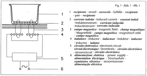
It exploits the electromagnetic properties of most cooking vessels.
The coil (inductor) which produces the electromagnetic field is operated and controlled by the electronic circuit.
The heat is transmitted to food by the cooking vessel itself.
The cooking process takes place as described below.
- loss of heat is minimum (high efficiency)
- the system stops automatically when the vessel is removed or even just lifted from the hob.
- the electronic circuit guarantees maximum flexibility and fine adjustments.
User’s Instructions
Installation
All operations relative to installation (electric connection) should be carried out by skilled personnel in conformity with the rules in force. As for the specific instructions see part pertaining to installer.
DO NOT STARE AT THE HALOGEN LAMP.
Use
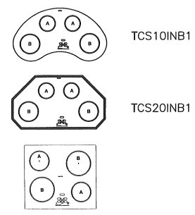
First place the pan in the chosen cooking zone. If the pan is not present the system cannot be switched on.
A. COOKING ZONE - INDUCTION ∅ 140
1400 W + BOOSTER 1800W
B. COOKING ZONE - INDUCTION ∅ 210
2300 W + BOOSTER 2500W
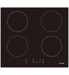
C. COOKING ZONE - HEATING ELEMENT VC ∅ 145
1200 W
D. COOKING ZONE - HEATING ELEMENT VC ∅ 180
1700 W
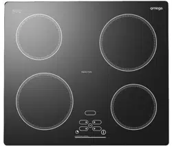
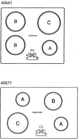
A. COOKING ZONE - INDUCTION ∅ 140
1400 W + BOOSTER 1800W
B. COOKING ZONE - INDUCTION ∅ 180
1850 W + BOOSTER 2500W
C. COOKING ZONE - INDUCTION ∅ 210
2300 W + BOOSTER 3200W
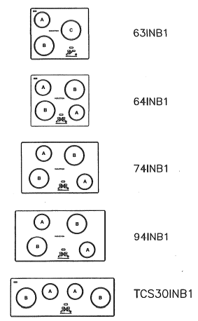
BASIC
BOOSTER OPTIONAL (MAX 2 HEATING ELEMENTS)
A. COOKING ZONE - INDUCTION ∅ 160 - 1400W
B. COOKING ZONE - INDUCTION ∅ 200 - 2300W
C. COOKING ZONE - INDUCTION ∅ 250 - 2300W
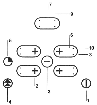
TOUCH CONTROL
Power ON/ Power OFF
Cooking zone +
Cooking zone -
Booster
timer
setting display
timer display
Dual circuit indicator led
Timer indicator led
Triple-circuit led
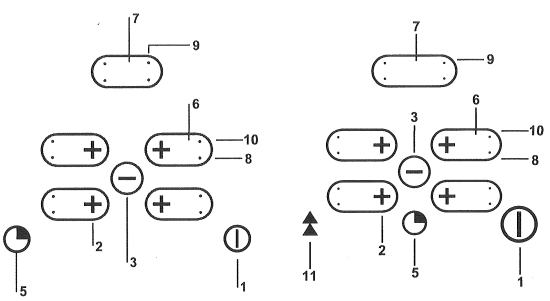
Power ON/ Power OFF
Cooking zone +
Cooking zone -
--------------
timer
setting display
timer display
Dual circuit indicator led
Triple Indicator led
Triple-circuit led
Booster
FUNCTIONS
1.1 Switching the Touch Control ON/OFF
(Fig. 2-2a)
After mains voltage is applied the control initialises for approx. 2.5-5 seconds before it is ready for operation. After a reset all displays and LEDs glow for approx. 1 second. When this time is over all displays and LEDs extinguish and the control is in the stand-by mode.
By operating the ON/OFF key the control can be turned into the ON-mode. The cooking zone displays show a static “0“. If a cooking zone is in the “hot“ status, the display shows alternating “H” and “0”. The bottom right dot is blinking in 1 second intervals on all cooking zone displays to indicate that no cooking zone is selected at the moment.
After switching-ON the electronic control remains activated for 20 seconds. If no cooking zone or timer selection follows within this period of time, the electronic control automatically switches back into the stand-by-mode.
The control can only be switched-ON if it identifies the ON/OFF akey alone being operated. Should it recognize key activation other than that, the control remains in the standby-mode.
If the child safety feature is active when switching on, all cooking zones show “L“, (LOCKED). (also refer to 1.11). If the cooking zones are in a “hot“ status, the display shows “L“ and “H“ in alternation. When the Touch Control is ON it can be switched-OFF at any time by operating the ON/OFF key. This is also valid if ( the control has been locked (activated child safety feature). The ON/OFF key has always priority in the switch-OFF function.
1.2 Automatic switch-OFF
When the control is ON it automatically switches-OFF after 20 seconds if no cooking zone or select key has been operated within this period of time. If case of a cooking zone selection, the automatic switch-OFF time is composed of 10 seconds deselection time for a cooking zone at setting“0“ and 10 seconds switch-OFF time.
1.3 Switching a cooking zone ON and OFF
If the control is ON the respective cooking zone can be selected by operating a cooking-zone-select-key (= PLUS-key of the respective cooking zone). There is a static dot indication in the respective display. If the cooking zone is hot “0” is displayed instead of “H” . On all other cooking zone displays the blinking dot extinguishes.Then a setting will be chosen by a renewed operation of the cooking- zone-select-key or the MINUS-key and the cooking zone begins to heat up. In order to use the cooking-zone-select-key as a PLUS-key the control has to recognize that after the selection the cooking zone has been released for 0,3 seconds.
After selection of a cooking zone the setting can be increased by continously pressing the PLUS-key, starting at step “1” it is increased by 1 step every 0,4 seconds. When setting “9” is reached the setting will not be changed further (end stop).
If the selected cooking zone will be switched ON by means of the MINUS key, the cooking zone starts at the maximum setting “9“ (“reverse switching-ON”). When the key is continuously operated, it decreases by 1 step every 0,4 seconds. When setting “0” is reached, there will be no further setting changed (end stop). Only a renewed operation of the MINUS (or PLUS) key changes the setting.
Switching OFF an individual cooking zone
To switch off an individual cooking zone, the respective cooking zone has to be selected with the cooking-zone-select-key (= PLUS). The selection is indicated with the static dot in the respective cooking zone display. If the control recognizes that the PLUS-(cooking-zone-select-key is the PLUS-key) and the MINUS-key have been activated simultaneously the setting of the selected cooking zone will be put back to “0“. Alternatively, the MINUS-key can be used to count down the setting to “0“.
If all cooking zones are at “0”, all decimal points in the cooking zone displays are blinking. If a cooking zone is “hot”, alternating “H” and “0”. When the sucepan is removed, the zone switches to the wait mode for 10 minutes. The letter H and the symbol alternate on the display the cooking zone then switches off and the letter H appears on the display.
Switching-OFF all cooking zones:
Immediate switching-OFF of all cooking zones can be achieved anytime by means of the ON/OFF key. In the stand-by-mode an “H“ appears on all cooking zones which are “hot“. All other cooking zone displays are not illuminated.
1.4 Power level
Cooking zone power can be adjusted to 9 levels, indicated by the symbols “1” to “9” on the 7-segment LED displays: The letter “P” on the display means that the cooking zone is working at maximum power. The letter “A” stands for automatic heating.
1.5 Pan sensor function
This activates automatically if a pan is not placed on the cooking zone within 2.5 seconds from when it was switched on.
The symbol appears on the display
1.6 Booster function
Select the cooking zone and then press the Booster button to enter this operating mode. The letter “P” appears on the display the power of the zone increases from rated power to a higher power for 10 minutes:
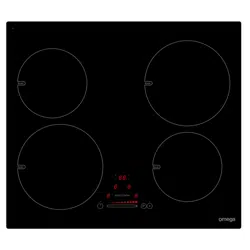
Mod. 4IN (G4)
Zone A- from 1400 to 1800 W
Zone B - from 1850 to 2500 W
Zone C-from 1850 to 2500 W
Zone D - from 2300 to 3200 W
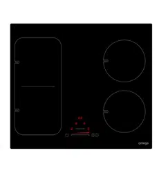
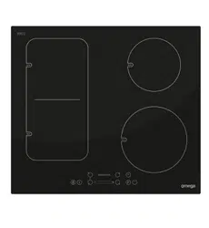
Combi mod. 2IN+2VC
Zone A-from 1400 to 1800 W
Zone B - from 2300 to 3200 W
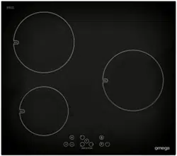
Mod. BASIC (BOOSTER)
∅160-from 1400 to 1850W
∅200 - from 2300 to 3000W
∅250 - from 2300 to 3000W
This function may terminate ahead of time if:
- The (-) button for the “P” zone is touched
- If the temperature of the zone or system is too high
- If the pan is removed for more than 10 minutes
1.7 Combi models: switching on.
Multiple heating elements
All the circuits are switched on at the same time.
1.8 Residual heat indicator
It is meant to indicate to the user that the glass ceramic has a dangerous touch temperature in the circumference of a cooking zone. The temperature will be determined following a mathematical model and the remaining residual heat will be indicated by means of “H” on the corresponding 7-segment-display.
Heating-up and cooling down will be calculated dependent on
• the selected setting („0“ to „9“)
• the ON/OFF time of the relays
After switching-OFF the cooking zone the respective display shows “H” until the assigned cooking zone temperature is mathematically in a uncritical level. (≤ 60°C).
1.9 Protection against unintended switching-ON
If the electronic control realizes a continuous operation of keys for approx. 10 seconds, it switches OFF automatically. The control sends out an audible failure signal for 10 seconds, so that the user can remove the object which has been mistakingly placed onto the operation surface. The displays show the failure code “ E R 0 3 “.
If the failure carries on for more than 10 seconds, only the code “ E R 0 3 “ will be displayed as long as the failure will be recognized by the electronic control. If the cooking zone is in the “hot” status, “H“ will appear on the display in alteration with the failure notice.
If no cooking zone will be activated within 20 seconds after switching-ON by means of the Power-key, the control switches back from the ON-condition into the stand-by-mode, (also see paragraph 1.2)
When the control is switched-ON the ON/OFF-key has priority over all other keys, so that the control can be switched-OFF anytime, even in case of multiple or continous operation of keys.
In the stand-by mode a continous operation will not be signalized. However, before the electronic control can be switched-ON again, it has to recognize that all keys are not operated.
1.10 Key lock (child safety feature)
Child safety feature;
Key lock:
After switching-ON the control the child safety feature can be activated. To achieve this it is necessary to simultaneously operate the front right cooking-zone-select-key and the MINUS-key and then press the front right cooking-zone-select-key again. There will be an “L” , meaning LOCKED (child safety feature against unintended switching-ON). If a cooking zone is in the “hot” condition, “L” and “H” will be displayed in alternation.
This course of operation has to take place within a period of 10 seconds, no other key than described above may be operated. Otherwise the input will be interrupted because of incompleteness, the cooktop will not be locked then.
The electronic control remains in a locked condition until it gets unlocked, even if the control has been switched-OFF and -ON in the meantime. Also a reset of the control (after a voltage drop) does not cancel the key lock.
Unlocking for cooking purposes:
To unlock and operate the control it is required to operate the front right cooking-zone-select-key and the MINUS-key simultaneously. “L“ (LOCKED) in the display extinguishes and all cooking zones show “0“ with a blinking dot. Should a cooking zone be “hot”, “H” is displayed instead of the static “0”. After switching-OFF the control, the child safety feature is active again.
Cancelling the key lock:
After switching-ON the control the child safety feature can be deactivated. Here it is necessary to simultaneously operate the front right cooking-zone-select-key and the MINUS-key and then operate the MINUS-key alone. If all steps have been carried out in the right order within 10 seconds the key lock gets cancelled and the control is OFF. Otherwise the input will be considered incomplete, the control remains locked and switches-OFF after 20 seconds. After a renewed switching-ON by means of the ON/OFF key all displays show „0“, the display dots are blinking and the control is ready for cooking. If a cooking zone is “hot“ , “H“ will be displayed instead of the static „0“.
1.11 COMBI MODELS: partial switch-off of multiple circuits
Depending on the design it is possible to operate dual- or triple-circuit radiant heating elements with the LITE-Touch Control.
When a multi-circuit heating element is put into operation, all heating circuits are switched-ON at the same time. If only the inner heating circuits should be used, the outer heating circuit can be switched-OFF by means of the multi-circuit key or in individual steps.
By operating the multi-circuit key the respective outer circuit of the assigned active cooking zone (setting „0“) can be cutoff anytime. An activated outer circuit will be indicated by an additional LED. A renewed operation of the multi-circuit key will add the outer circuit(s) at any time, the assigned LED's glow again (toggle-function)
If a cooking zone other than the one with multi-circuit function will be selected, the multicircuit status will be changed and all cooking zones will be deselected (the decimal point extinguishes).
Behaviour of dual-circuit cut-OFF:
If the heating element to be controlled is a triple-circuit heating element, the course of action is as follows:
• The first activation of the multi-circuit key cuts-off the outer heating circuit and the top LED extinguishes.
• A second activation of the multi-circuit-key cuts-off the middle heating circuit, (also the bottom LED extinguishes.)
• A third activation adds the middle heating circuit again. A further activation adds the third heating circuit as well and the assigned LEDs glow again.
1.13 Audible signal (buzzer)
While the control is in operation the following activities will be signaled by means of a buzzer:
• normal key activation with a short sound signal.
• continous operation of keys over a longer period of time (_10 seconds ) with a longer, intermittend sound signal.
1.12 Timer function (optional)
The timer function is realized in two versions:
• Stand-alone timer 1..99 min: sound signal when the time is over (= minute minder). This function is only available when the cooktop is not in operation, i.e. when there is no cooking.
• Cooking zone timer 1 ..99 min: sound signal when the time is over, four cooking zones can be programmed independently.
Timer as minute minder (stand-alone):
• If the control is ON the standalone-timer con be operated by activating the timer key all cooking zone are on position “0”. The timer display shows “00” without any activation. Within 10 sec. the timer in cut-off..
• Adjustment range (0-99min), it can be set in 1-minute steps with TIMER key, starting at 1 up to 99 (end stop) with the minus-key starting at 99 down to 0 (end stop).
• Continuous activation of the TIMER or minus-keyresults in a dynamic increase of the adjustment speed up to maximum value without sound signal.
• When the TIMER or minus key is released in the meantime, the adjustment speed starts again from a (low) initial value.
• Adjustment can be made with a continously activated TIMER or minus-key or by tip-operation (with sound signal)
After the timer is set the time runs down according to the adjustment.
• When the time is over there is a sound signal and the timer display blinks with “00”.
The sound signal will be stopped
• automatically after 2 minutes and/or
• by operating any key.
Then the blinking of the timer display stops and the display extinguishes.
Switching-OFF/changing the timer
• The timer can be changed or switched-off anytime by operating the timer or minus key (with sound signal). The timer will be switched off by counting down to “0” with the minus-key or by operating the timer and minus-key together, which sets the timer directly to “0”.
• The timer can be also switched off by pressing the power key twice.
Timer programming on cooking zones
When the control is switched-ON an independent timer can be programmed for every cooking zone.
• By selecting a cooking zone with the cooking-zone-select-key, then selecting the setting and finally activating the timer-select-key, the timer can be programmed as a switch-off function for a cooking zone. Around the timer four LEDs are arranged. These indicate for which cooking zone the timer has been activated.
• As soon as the timer has been selected, the assigned timer-LED blinks and the dot in the timer display glows. If a cooking-zone-select-key will be operated, the dot in the timer displays extinguishes and the LED does not blink any longer.
• When switching-over from one cooking zone to another, the timer display always shows the present timer value of the respective cooking zone. However, the programmed timers of other cooking zones remain active.
• The further setting behaviour corresponds to the STAND-ALONE-TIMER. For increasing the adjusted time, the PLUS-key of the respective cooking zone has to be used, (setting “0“)
• When the timer has run down, there is a sound signal and the timer display shows “00“ statically, the assigned cooking zone timer LED blinks. The programmed cooking zone will be cut off and „H“ will be displayed if the coking zone is hot, otherwise a stroke will show in the cooking zone display.
The sound signal and the blinking of the timer LED will be stopped
• automatically after 2 minutes
• by operating any key.
The timer display extinguishes.
• The basic behaviour follows the description of the “minute minder” (stand-alone-timer).
Precautions
- in case you detect a crack, however small, in the hob surface, immediately disconnect the power supply
- when the hob is in use keep all magnetizable objects away (credit cards, floppy disks, calculators and so on)
- do not use any alluminium foil or place any foodstuffs wrapped in alluminium foil directly on the hob
- do not place any metal objects such as knives, forks, spoons and lids on the hob surface as they will heat up
- when cooking in a nonstick pan without seasoning, do not exceed 1-2 minutes’ pre-heating time
- when cooking food that may easily stick, start at a low power output level and then slowly increase while regularly stirring.
- after cooking is finished, switch off using the control provided (turn down to “0”), and do not rely on the pan sensor.
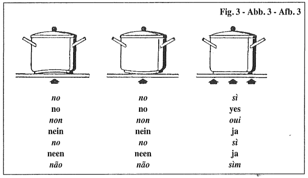
Cooking vessels
(Fig. 3)
- a magnet-attracting vessel may be a suitable vessel for induction cooking
- prefer vessels which are especially declared to be suitable for induction cooking
- flat- and thick-bottomed vessels
- a vessel with a 20-centimeter diameter ensures the maximum exploitation of power
- a smaller vessel reduces power exploitation, but does not cause any energy loss
We would anyhow not recommend the use of vessels with diameters smaller than 10 cm.
- stainless-steel vessels with multi-layer or ferritic stainless-steel bottoms when specifically suited for induction cooking
- cast-iron preferably enamel-bottomed vessels to avoid scratching the pyroceram surface
- we do not recommend the use of any glass, ceramic, earthenware, alluminium, copper or non-magnetic (austenitic) stainless-steel vessels.
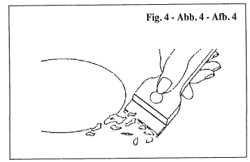
Maintenance
(Fig. 4)
By means of a scraper immediately remove any alluminium foil bits, food spills, grease splashes, sugar marks and other high sugar-content food from the surface in order to avoid damaging the hob. Subsequently clean the surface with some paper towel and SIDOL or STANFIX, rinse with water and dry by means of a clean cloth.
Under no circumstance should sponges or abrasive cloths be used; also avoid using aggressive chemical detergents such as oven sprays and spot removers.
DO NOT USE STEAM CLEANERS
Installer’s Instructions
Installation
These Instructions are for the qualified technician, as a guide to installation, adjustment and maintenance, according to the laws and standards in force. These operations must always be carried out when the appliance has been disconnected from the electric system.
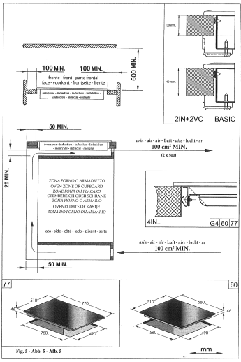
Positioning
(Fig. 5)
The fixture is especially designed for fitting into a work-top as shown in the corresponding figure.
Place the supplied sealing agent along the hob perimeter.
Do not install the hob over an oven; in case you do, make sure of the following:
- the oven is equipped with an appopriate cooling system
- there is no warm-air leakage from the oven towards the hob
- suitable air-inlets are provided as shown in the figure.
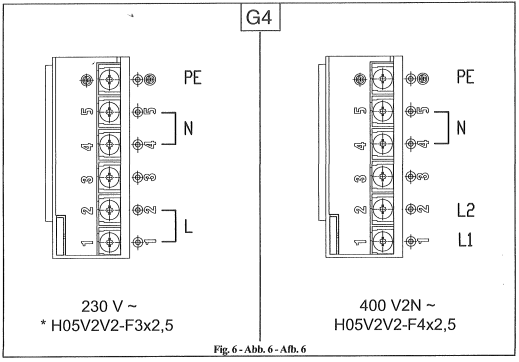
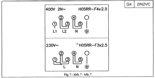
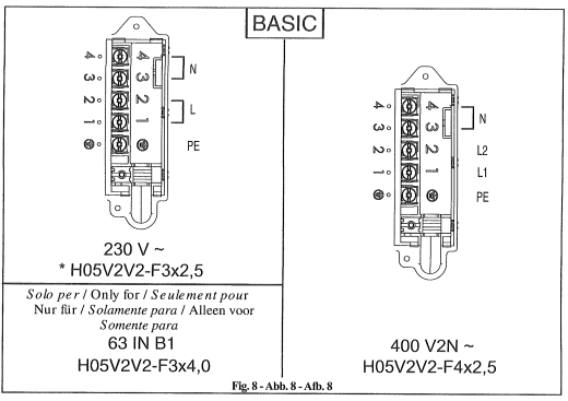
Electrical connection
(Fig. 6-7-8)
Prior to carrying out the electrical connection, please ensure that:
- the plant characteristics are such as to follow what is indicated on the matrix plate placed at the bottom of the working area;
- that the plant is fitted with an efficient earth connection, following the standards and law provisions in force. The earth connection is compulsory in terms of the law.
Should there be no cable and/ or plug on the equipment, use suitable absorption material for the working temperature as well, as indicated on the matrix plate. Under no circumstance must the cable reach a temperature above 50°C of the ambient temperature.
If connecting directly to the mains power supply, fit a multi-pole switch of a suitable size for the rated capacity with a clearance distance which completely disconnects the power line under overvoltage category III conditions, consistently with the rules of installation (the yellow/ green earth wir must not be interrupted). The plug or omnipolar switch must be easily reached on the installed equipment.
The manufacturers decline any responsibility in the event of non-compliance with what is described above and the accident prevention norms not being respected and followed.
To avoid all risk, if the power cable becomes damaged, it must only be replaced by the manufacturer, by an authorised service centre, or by a qualified electrician.
* Considering contemporaneity factor
* Considering contemporaneity factor
CAUTION
The appliance is not intended for use by young children or infirm persons unless they have been adequately supervised by a responsible person to ensure that they can use the appliance safely.
Young children should be supervised to ensure that they do not play with the appliance.
If the supply cord is damaged, it must be replaced by the manufacturer or its service agent or a similarly qualified person in order to avoid a hazard.
Do not use a steam cleaner with to clean this appliance.
WARNING: If the surface is cracked, switch off the appliance to avoid the possibility of an electric shock
Metallic objects such as knives, forks, spoons and lids should not be placed on the hotplate since they can get hot
Please centrally locate the hob within the cut-out in the bench, allowing an equal distance of 10mm on each side.
 is not present the system cannot be switched on.
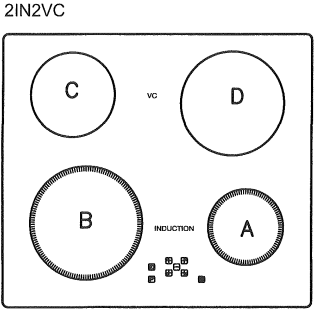
 alternate on the display the cooking zone then switches off and the letter H appears on the display.
 „0“) can be cutoff anytime. An activated outer circuit will be indicated by an additional LED. A renewed operation of the multi-circuit key will add the outer circuit(s) at any time, the assigned LED's glow again (toggle-function)