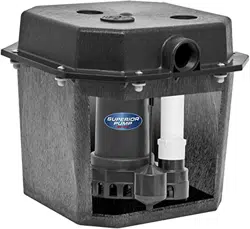
Installation & Operation Manual Remote Sink/Drain Pump System
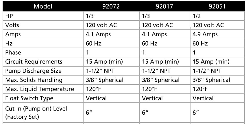
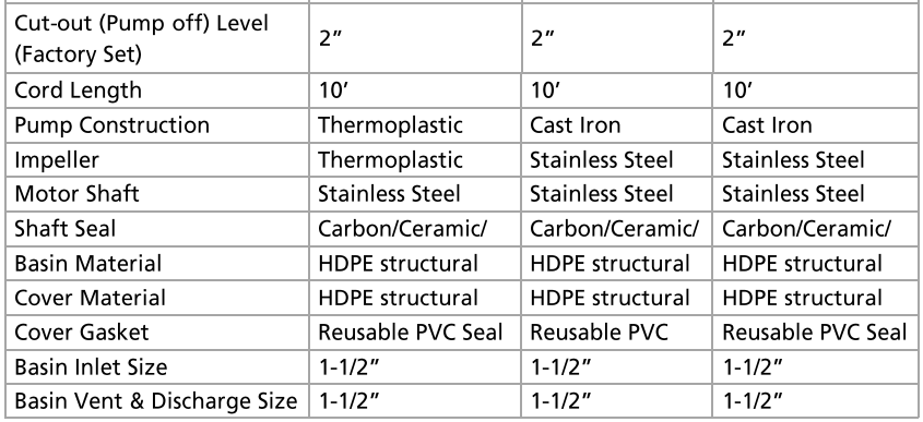
Specifications
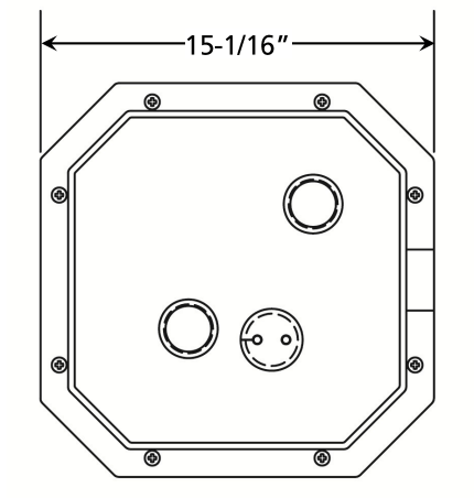
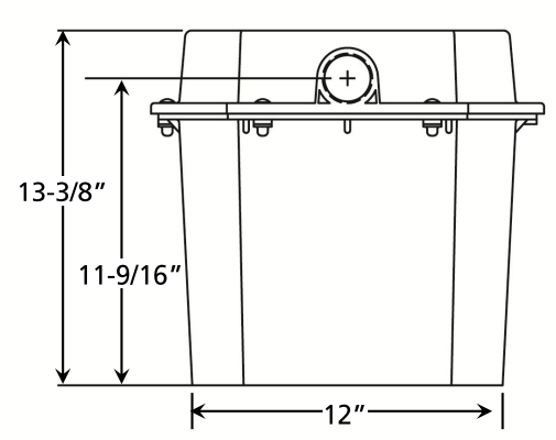
Dimensions
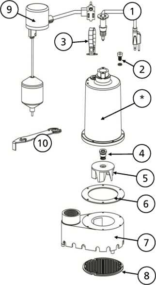
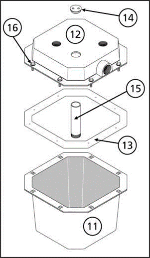
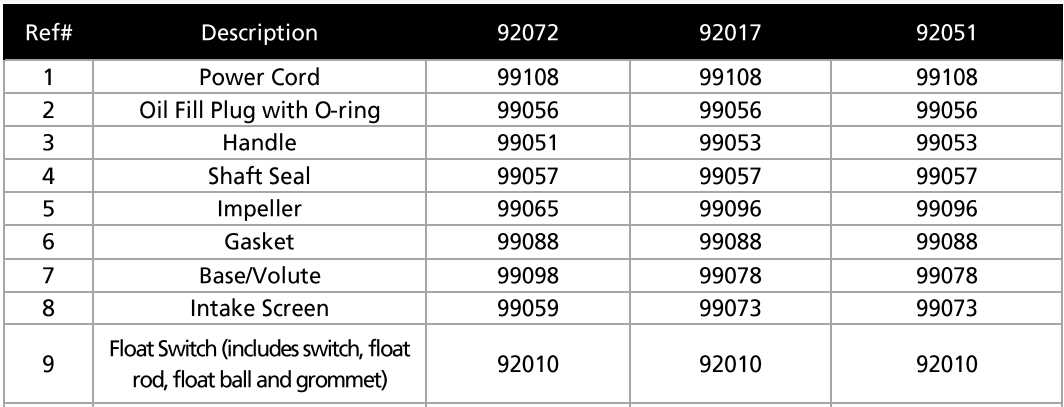
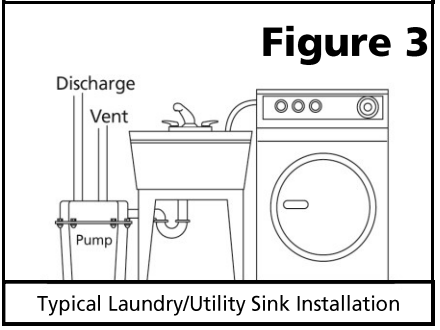
Replacement Parts
*lf motor fails, replace entire pump
Installation
1. This pump kit is pre-assembled for easy installation. Inspect the kit for possible shipping damage prior to installation.
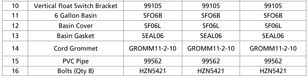
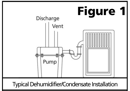
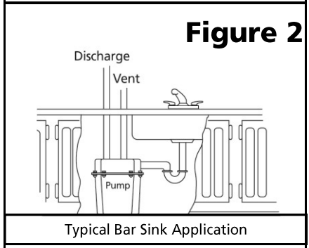
2. The basin should be located at the lowest point relative to the area to be drained. See Figures 1, 2 & 3 for typical installations.
3. Make sure that the inlet of the pump is lower than the water level to be pumped.
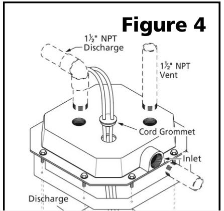
4. Install the inlet pipe into the inlet port on the basin as shown in Figure 4. Use Teflon tape or a sealant compatible with plastic to seal any threaded fittings. NOTE: If using plastic pipe (PVC or ABS), do not use ordinary pipe joint compound. This compound can degrade plastic pipe and fittings. Use Teflon tape or sealant compatible with plastic pipe.
5. Install the discharge pipe to the discharge port on the basin as shown in Figure 4. Install an in-line check valve in the discharge line as close to the basin as possible. This will prevent backflow into the basin when the pump shuts off. NOTE: To reduce pumping noise, a check valve with rubber boots can be installed on the discharge pipe to dampen noise and vibration.
6. Install the vent pipe to the vent port on the basin as shown in Figure 4. The pipe should not extend into the basin. Connect the vent line to the sewer vent system.
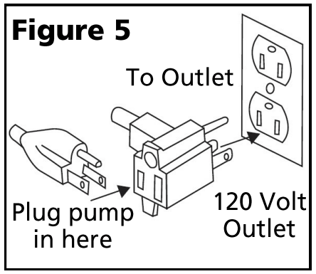
7. This pump is designed for 120 Volt, 60 Hz. operation and requires a minimum 15 amp individual branch circuit. Both the pump and float switch are supplied with 3 prong, grounding type plugs. The float switch is plugged directly into the outlet. The pump plugs into the piggy-back plug on the float switch plug. See Figure 5.
8. If the pump discharge pipe will be exposed to freezing conditions, the exposed portion of the pipe must be installed so any remaining water in the pipe will drain by gravity. Failure to do this can cause water trapped in the pipe to freeze which could result in damage to the pump, piping and personal property.
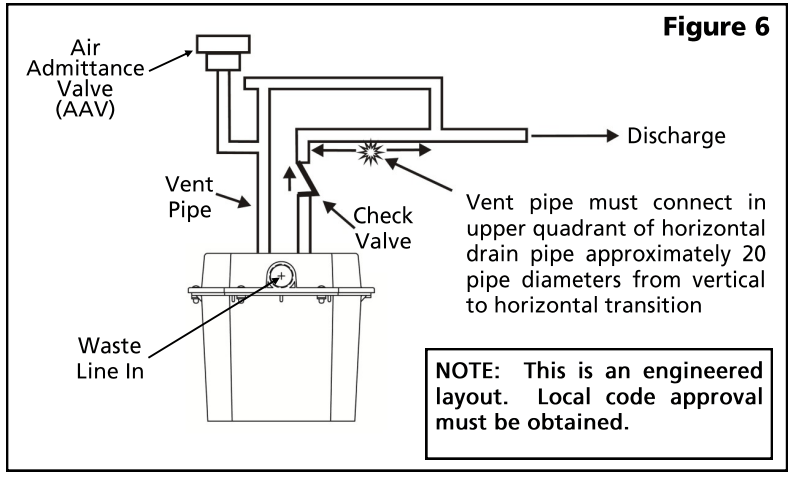
Air Admittance Valve (AAV)
The use of an Air Admittance Valve (AAV) may be used with this kit if local codes permit. Follow the piping instructions in Figure 6 for proper installation of the AAV.
Operation
1. After the piping and electrical supply have been installed and connected, the unit is ready for operation.
2. Check operation by filling the basin with water and observing the pump through at least one complete cycle.
3. Check for leaks and make any necessary adjustments at this time.
Maintenance
1. Periodically inspect and clean the anti-airlock hole.
2. Inspect the float switch for any accumulated debris that may inhibit it from operating properly. Clean if necessary.
3. The pump has sealed, permanently lubricated bearings and require no additional lubrication
4. In applications where the pump may not activate for extended periods of time, it is recommended to cycle the pump at least once per month to ensure the pumping system is working properly when needed.
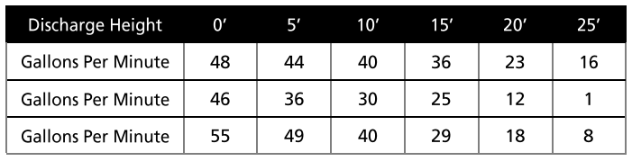
Performances
Height and/or piping restriction will reduce the pump output performance. It is recommended to use the same size or larger pipe as the pump discharge for optimum performance.
Troubleshooting
Problem
Possible Causes
How to Correct
If the pump does not start or run
Pump is not plugged in, switch or breaker is turned off
Plug pump in or turn on switch/breaker
Check for blown fuses or tripped circuit breakers or tripped GFCI outlets
Replace fuse, reset breaker, reset GFCI outlet
Float switch is defective
Check and replace if necessary
Motor thermal protector tripped
Allow pump to cool. Pump will reset automatically
Float switch is stuck or obstructed
Remove obstruction or position pump so it will not become stuck
The pump cycles too frequently or runs periodically when fixtures are not in use.
Backflow of water from discharge pipe
Install or replace check valve
Float switch is defective
Replace float switch
Fixtures are leaking
Repair Fixtures to eliminate leakage
If the pump runs but moves little or no water
Obstructed discharge hose/pipe
Remove obstruction
Frozen discharge hose/pipe
Allow hose/pipe to thaw
Pump is air locked
Remove
Low line voltage
Check wire size and increase if necessary
Check valve is stuck in the closed position or defective
Inspect, repair or replace if necessary
Check valve is installed backward
Make sure valve is installed in the correct direction of flow
Worn, damaged or clogged pump parts
Inspect for wear, damage or clog and clean or replace part if necessary
Discharge head exceeds pump capacity
If pumping height is over 25', the pump will not move water. See performance chart
#1 Will this serve two washers in our laundry room?
In my opinion, this pump doesn’t have the capacity for two washers working simultaneously. Check with a plumber or manufacturer.
#2 Can you drain a washing machine directly into this pump or does it have to go through a sink?
Yes you can drain directly from the washer to this kit as long as it is properly.
#3 Will this serve two washers in our laundry room?
In my opinion, this pump doesn’t have the capacity for two washers working simultaneously. Check with a plumber or manufacturer.
#4 Anyone have any tips on keeping these clean / free of mold and odors? Septic friendly!
Use a solution of bleach and water every couple of weeks. Keep the solution in the tank for a while. That should prevent mold and reduce odors. The kit should only be used for sink/laundry water.
#5 Could this work in a crawlspace as a sump pump?
It's designed for a sink drain pump. You would want a pump set up a little different.