
P/NO : MFL42540226
www.lg.com
INSTALLATION MANUAL
• Please read this installation manual completely before installing the product.
• Installation work must be performed in accordance with the national wiring
standards by authorized personnel only.
• Please retain this installation manual for future reference after reading it
thoroughly.
MODEL : PRVC1
Low Ambient Control Kit

Low Ambient Control Kit Installation manual
TABLE OF CONTENTS
■ Safety Precautions................................................................................3
■ Accessory Parts ....................................................................................5
■ Name of each part ................................................................................6
■ Installation Method................................................................................7
1. Single unit install Guide....................................................................7
2. Series unit install Guide..................................................................11
3. Unit Placement and Clearances.....................................................15
■ Setting and using method ...................................................................17
1. Power source input.........................................................................17
2. Wiring for Low Ambient Control PCB and transformer...................19
3. Wiring for Damper Actuator............................................................20
4. Setting of ‘SWDIP’..........................................................................21
5. Setting of outdoor unit dip switch ..................................................22
2 Low Ambient Control Kit
■ During installation
Safety Precautions
To prevent injury to the user or other people and property damage, the following instructions
must be followed.
■ Incorrect operation due to ignoring instruction will cause harm or damage. The seriousness is
classified by the following indications.
■ Meanings of symbols used in this manual are as shown below.
WARNING
CAUTION
This symbol indicates the possibility of death or serious injury.
This symbol indicates the possibility of injury or damage.
Be sure not to do.
Be sure to follow the instruction.
WARNING
Installation manual 3
Safety Precautions
Please install the
designated location in the
Control box.
• It can cause the breakdown
or accident.
Do not touch the board
when the power is
connected .
•
It can cause a fire, electric
shock, explosion, injury and
problem to the product.
Always request for
installation of the product to
the service center or the
installation service provider.
•
It can cause a fire, electric
shock, explosion and injury.
When reinstalling the previously
installed product, request for service to
the service center or the installation
service provider.
•
It can cause a fire, electric shock, explosion and
injury.

■ During use
4 Low Ambient Control Kit
Safety Precautions
Do not modify or extend the
power cord.
• It can cause a fire and
electric shock.
Do not pour water inside the
product.
• It can cause an electric
shock and problem to the
product.
When the product is submersed
in water, always request for
service to the service center or
the installation service provider.
• It can cause a fire and
electric shock.
Make the children and the
elderly use the product with
the help of a guardian.
• It can cause a safety
accident and problems to
the product.
Do not give impact to the
product.
• It can cause problem to the
product.
Installation manual 5
Accessory Parts
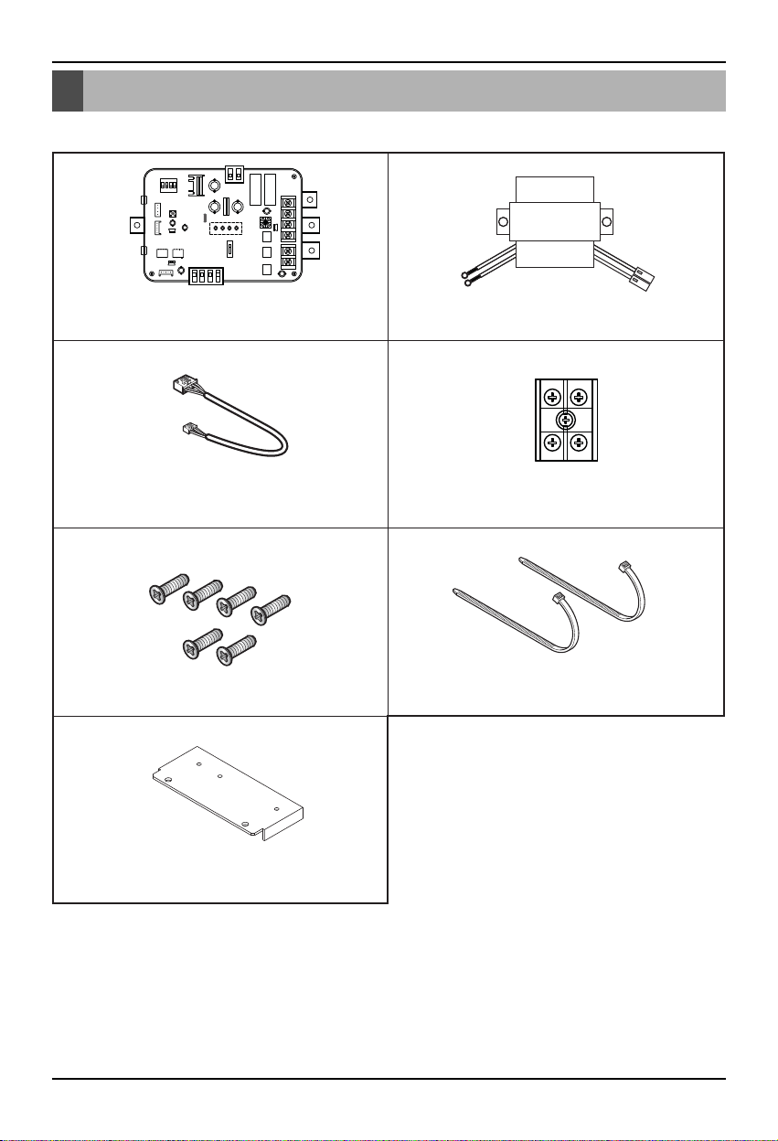
Accessory Parts
Cable Assy Terminal Block Assy
Tie (2EA)
Low Ambient Control PCB Transformer
Screw (6EA)
Panel 1EA
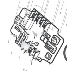
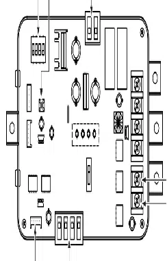
Name of each part
6 Low Ambient Control Kit
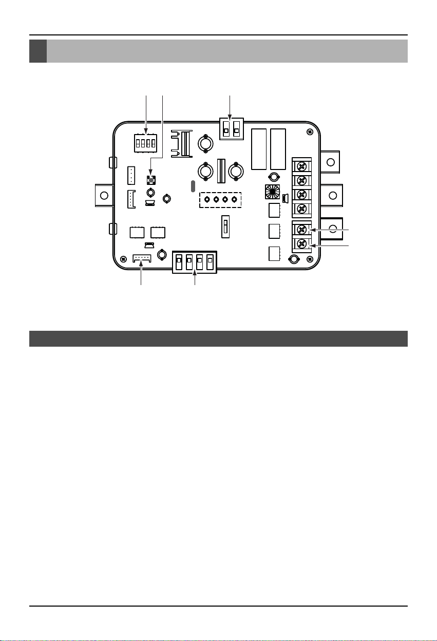
1. CN_PWR : Power input terminal(DC 12V)
2. CN_AO : Signal output terminal to control a damper actuator
3. CN_OUT : Outdoor unit connector
4. BUS_A : RS-485 (+) terminal
5. BUS_B : RS-485 (-) terminal
6. SWDIP : Switch to select main function
7. SW1 : Reset switch
Low Ambient Control Kit
16 7
3 2
4
5
Name of each part
Installation manual 7
Installation Method
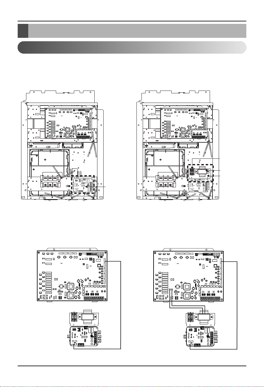
1. Shut off the main power line of outdoor unit.
2. Install the LAC(Low Ambient Control) PCB in the control box by using screws.
3. Install the panel assy in the control box by using screws.
4. Connect the Main PCB(CN41) to LAC(CN_OUT) by using the cable assy.
5. Connect the blue wire of transformer to the Main PCB (JIG1(L), JIG2(N)).
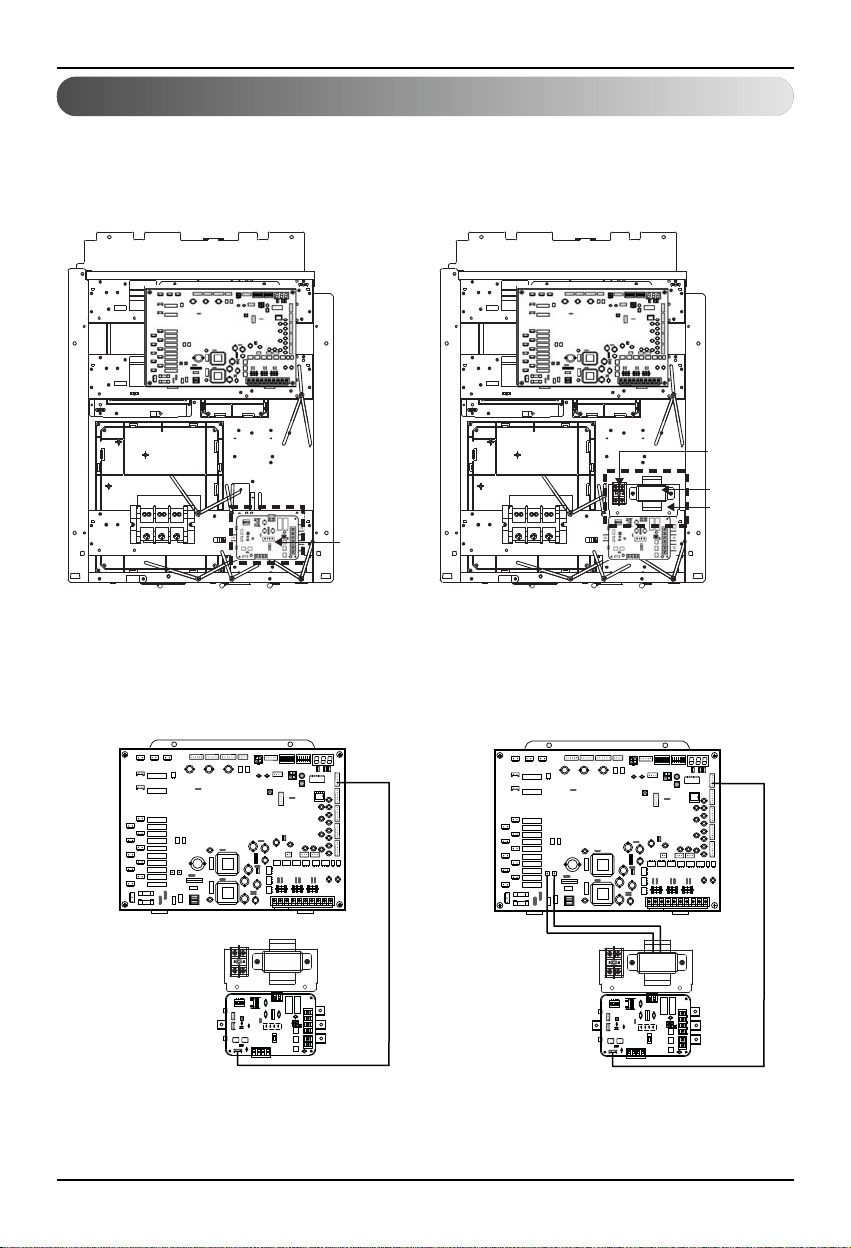
1. Single unit install Guide
Installation Method
LAC PCB
Step 2 Step 3
Terminal block
Transformer
Panel
Step 4 Step 5
CN41
CN_OUT
GND
JIG1(L)
JIG2(N)
Installation Method
8 Low Ambient Control Kit
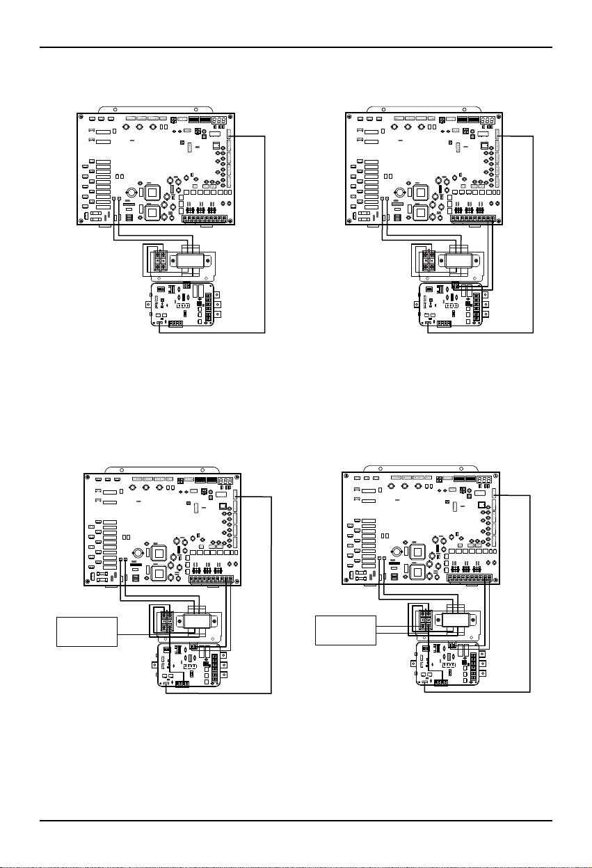
6. Connect the red wire of transformer to the terminal block (2Pin yellow terminal block).
7. Connect a power cable (DC 12V) to CN_PWR (12V, GND) of LAC
8. Connect the common wire of Damper Actuator to the terminal block and connect the wire of
LAC(CN_AO(GND(A-)) to the common wire of Damper Actuator.
9. Connect the wire of AC 24V of Damper Actuator to the terminal block
Step 6 Step 7
GND 12V
CN_PWR
Step 8 Step 9
AC 24V Power
for Damper Actuator
of Master
GND
Common
AC 24V Power
for Damper Actuator
of Master
AC 24V
GND
Common
Installation Method
Installation manual 9
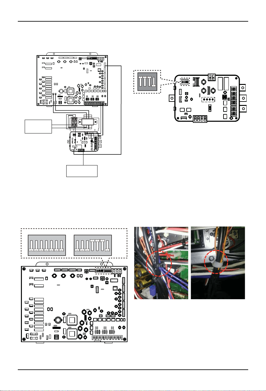
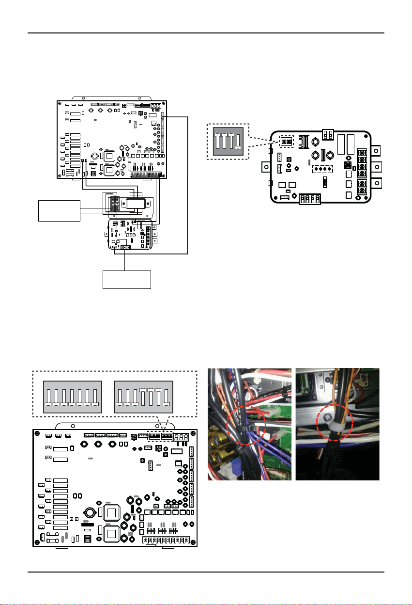
10. Connect the wire of control signal of Damper Actuator to CN_AO(AO_01(A+)) of LAC
11. Set up the main function dip switch of LAC PCB.
12. Set up the dip switch of MAIN outdoor unit PCB.
13. Using the clamp and tie provided securely attach the wire as shown in the figure.
Step 10 Step 11
ON
1234
AC 24V Power
for Damper Actuator
of Master
DC 0~10V Control Signal
for Damper Actuator
of Master
Master(AO_01(A+))
Step 12 Step 13
ON
SW01B SW02B
1234567
ON
1234567
10 Low Ambient Control Kit
14. Turn on the main power line of outdoor unit.
15. Check the signal to CN_AO(AO_01, GND) of LAC and Air Damper.
Step 14,15
Installation manual 11
2. Series unit install Guide
1. Shut off the main power line of outdoor unit.
2. Install the LAC(Low Ambient Control) PCB in the control box by using screws.
3. Install the panel assy in the control box by using screws.
4. Connect the Main PCB(CN41) to LAC(CN_OUT) by using the cable assy.
5. Connect the blue wire of transformer to the Main PCB (JIG1(L), JIG2(N)).
LAC PCB
Step 2 Step 3
Terminal block
Transformer
Panel
Step 4 Step 5
CN41
CN_OUT
GND
JIG1(L)
JIG2(N)
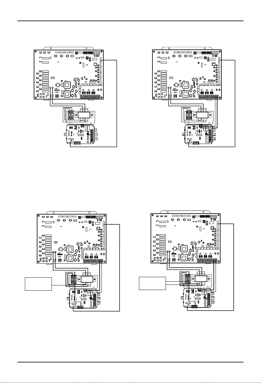
Installation Method
12 Low Ambient Control Kit
6. Connect the red wire of transformer to the terminal block (2Pin yellow terminal block).
7. Connect a power cable (DC 12V) to CN_PWR (12V, GND) of LAC
8. Connect the common wire of Damper Actuator of Master Unit & Slave Unit to the terminal block and connect the
wire of LAC(CN_AO(GND(A-)) to the common wire of Damper Actuator of Master Unit & Slave Unit.
9. Connect the wire of AC 24V of Damper Actuator of Master Unit & Slave Unit to the terminal block.
Step 6 Step 7
GND 12V
CN_PWR
Step 8 Step 9
AC 24V Power
for Damper Actuator
of Master & Slave
GND
Common
AC 24V Power
for Damper Actuator
of Master & Slave
AC 24V
GND
Common
Installation Method
Installation manual 13
10. Connect the wire of control signal of Damper Actuator of Master Unit to CN_AO(AO_01(A+)) and connect the
wire of control signal of Damper Actuator of Slave Unit to CN_AO(AO_02(B+))
11. Set up the main function dip switch of LAC PCB.
12. Set up the dip switch of MAIN outdoor unit PCB.
13. Using the clamp and tie provided securely attach the wire as shown in the figure.
Step 11
ON
1234
Step 10
AC 24V Power
for Damper Actuator
of Master & Slave
DC 0~10V Control Signal
for Damper Actuator
of Master & Slave
Master(AO_01(A+))
Slave(AO_02(B+))
Step 12 Step 13
ON
SW01B SW02B
1234567
ON
1234567
Installation Method
14 Low Ambient Control Kit
14. Turn on the main power line of outdoor unit.
15. Check the signal to CN_AO(AO_01, GND), (AO_02, GND) of LAC and Air Damper of Master Unit & Slave Unit.
Step 14,15
Installation Method
Installation manual 15
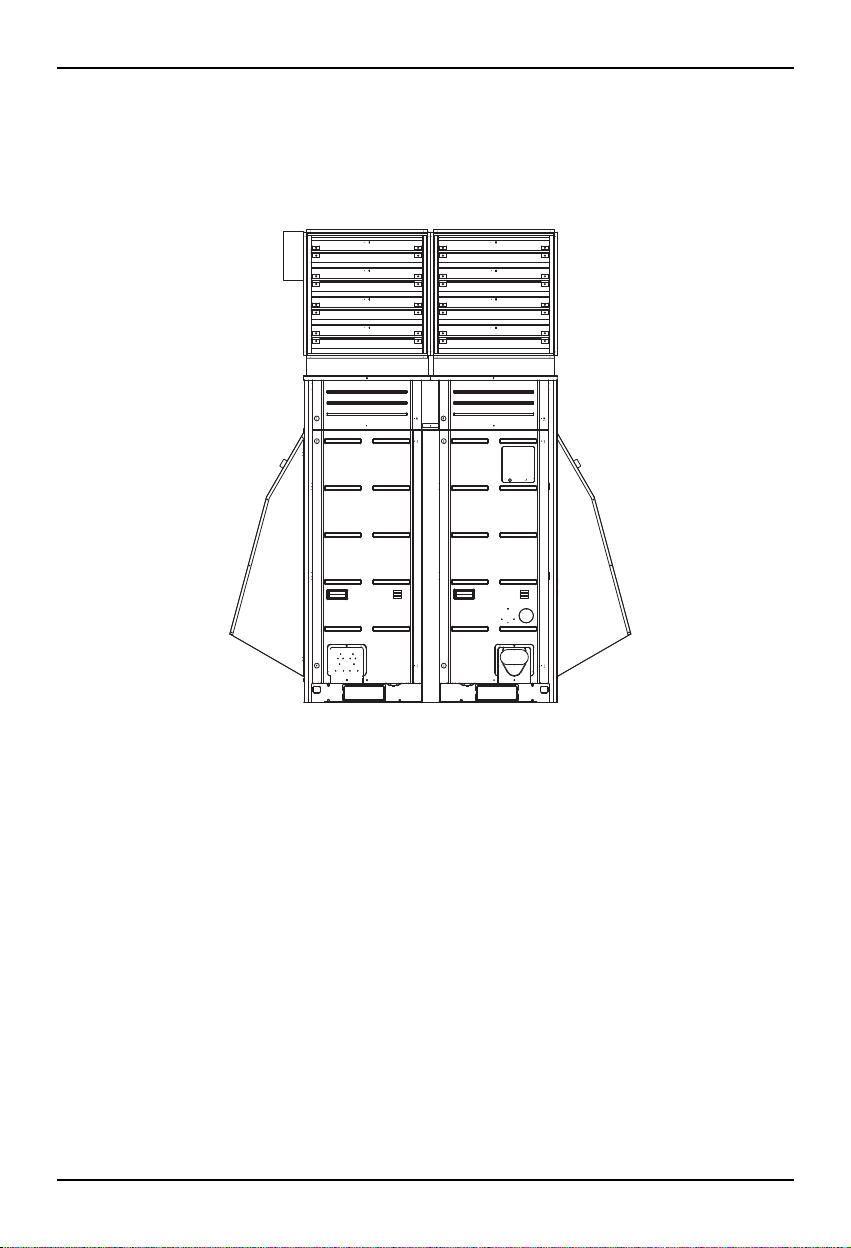
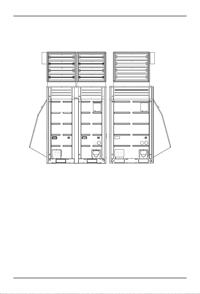
3. Unit Placement and Clearances
1. Outdoor units should be located in an area protected from prevailing winds. (shown below)
In high wind locations it may be advisable to locate the units within a walled area.
Top View
Prevailing wind
Building Wall
Outdoor Unit
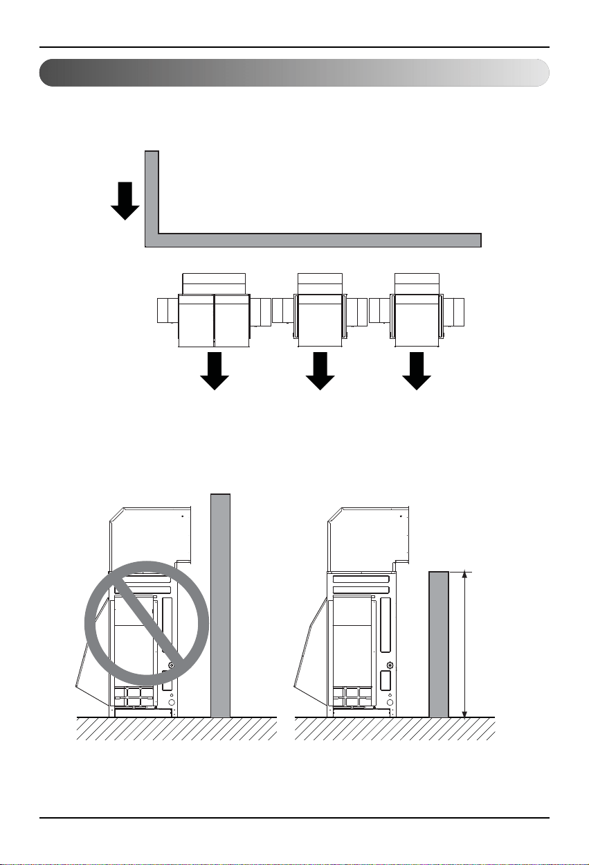
H ≤ discharge
of air damper
2. If the units are surrounded by an enclosure, the discharge of the air damper must direct the air out and over the
enclosure walls to prevent air recirculation.
Installation Method
16 Low Ambient Control Kit
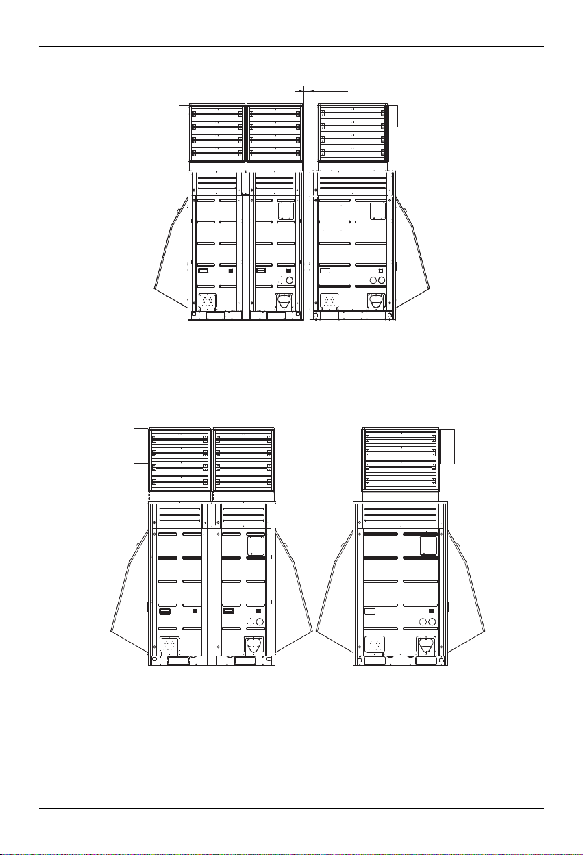
3. When units are combined they should be placed the minimum 30mm.
4. If units are placed further than 30mm apart, additional snow hoods may be required.
30mm
Installation manual 17
Setting and using method
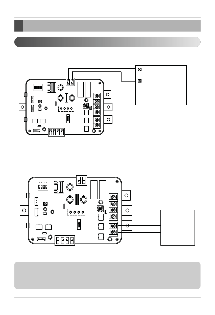
1. Power source input
■
When wiring power source from outdoor unit
Outdoor Unit
PCB
DC12V or DC15V
GND
12V GND
■
When using ODU Dry contact with Central Control Devices
Central
Control
Devices
BUS_A
BUS_B
Setting and using method
Notes
This device can accept only DC power input.
Do not input 220V AC. Otherwise it will cause a serious damage.
Using external power source is recommended.
18 Low Ambient Control Kit
Setting and using method
■
Communication and Power Line
- If communication and power lines are run alongside each other then there is a strong likelihood of
operational faults developing due to interference in the signal wiring caused by electrostatic and
electromagnetic coupling. The tables below indicates our recommendation as to appropriate spacing
of communication and power lines where these are to be run side by side.
Current capacity of power line Spacing
100V or more
10A 300mm
50A 500mm
100A 1,000mm
Exceed 100A 1,500mm
Notes
If the power supply waveform continues to exhibit some distortion the recommended spacing in the
table should be increased.
• If the lines are laid inside conduits then the following point must also be taken into account when
grouping various lines together for introduction into the conduits.
• Power lines (including power supply to air conditioner) and signal lines must not be laid inside the
same.
• In the same way, when grouping the lines power and signal lines should not be bunched together.
Installation manual 19
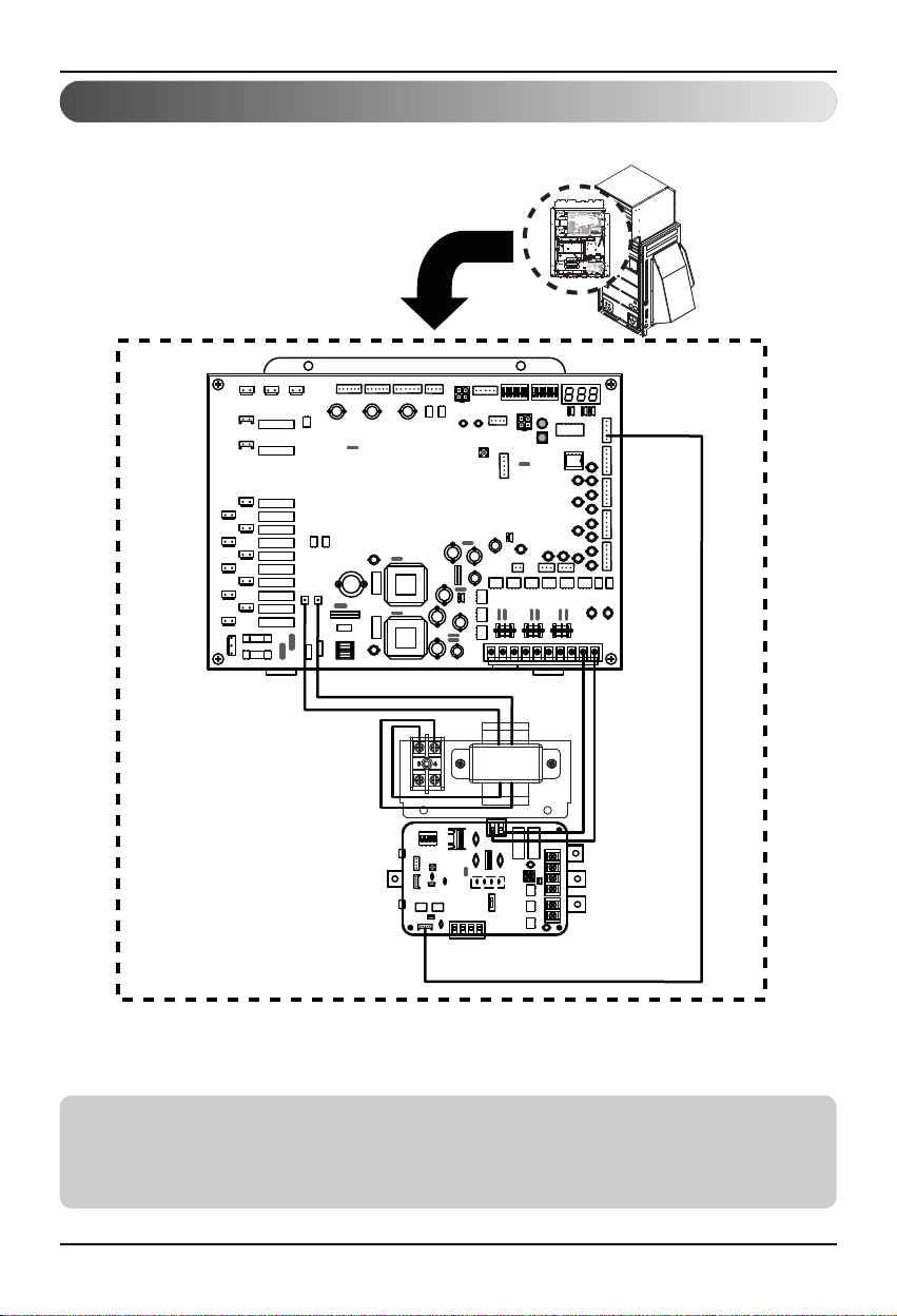
2. Wiring for Low Ambient Control PCB and transformer
Notes
This device can accept only DC 12V power input.
Do not input AC power. Otherwise it will cause a serious damage.
The power(DC 12V) line is recommended by AWG 22 (0.644mm, 0.053Ω/m).
Setting and using method
GND 12V
20 Low Ambient Control Kit
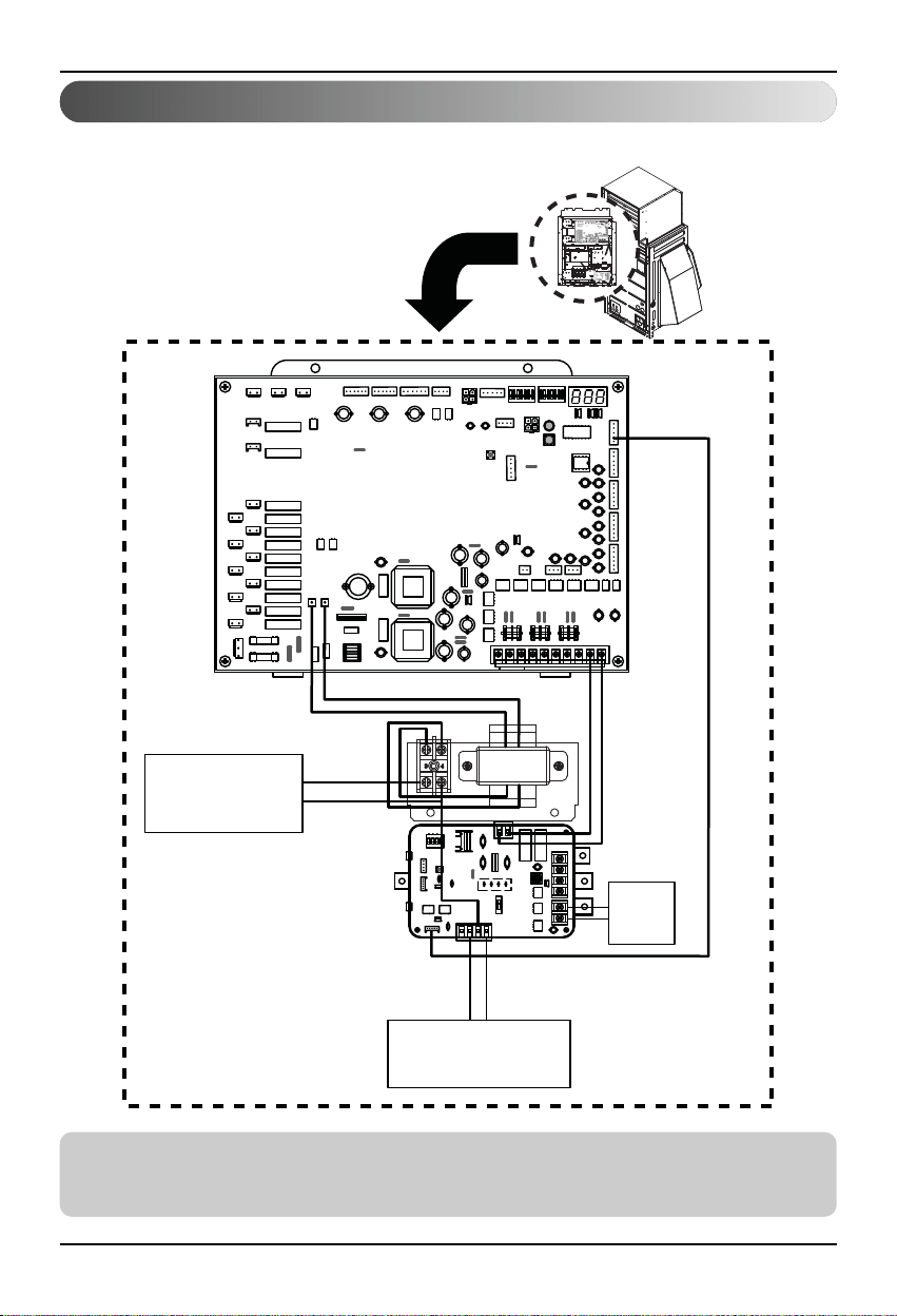
Setting and using method
AC 24V Power
for Damper Actuator
of Master & Slave
DC 0~10V Control Signal
for Damper Actuator
of Master & Slave
Central
Control
Device
AC 24V
GND
GND
12V
Common
Slave(AO_02(B+)) Master(AO_01(A+))
3. Wiring for Damper Actuator
Notes
The low ambient control PCB can control maximum two actuators.
The power (AC 24V) and signal (DC 0~10V) line is recommended by AWG 22 (0.644mm, 0.053Ω/m).
Installation manual 21
Setting and using method
Notes
After change ‘SWDIP’ setting, then you must press reset switch to reflect the setting.
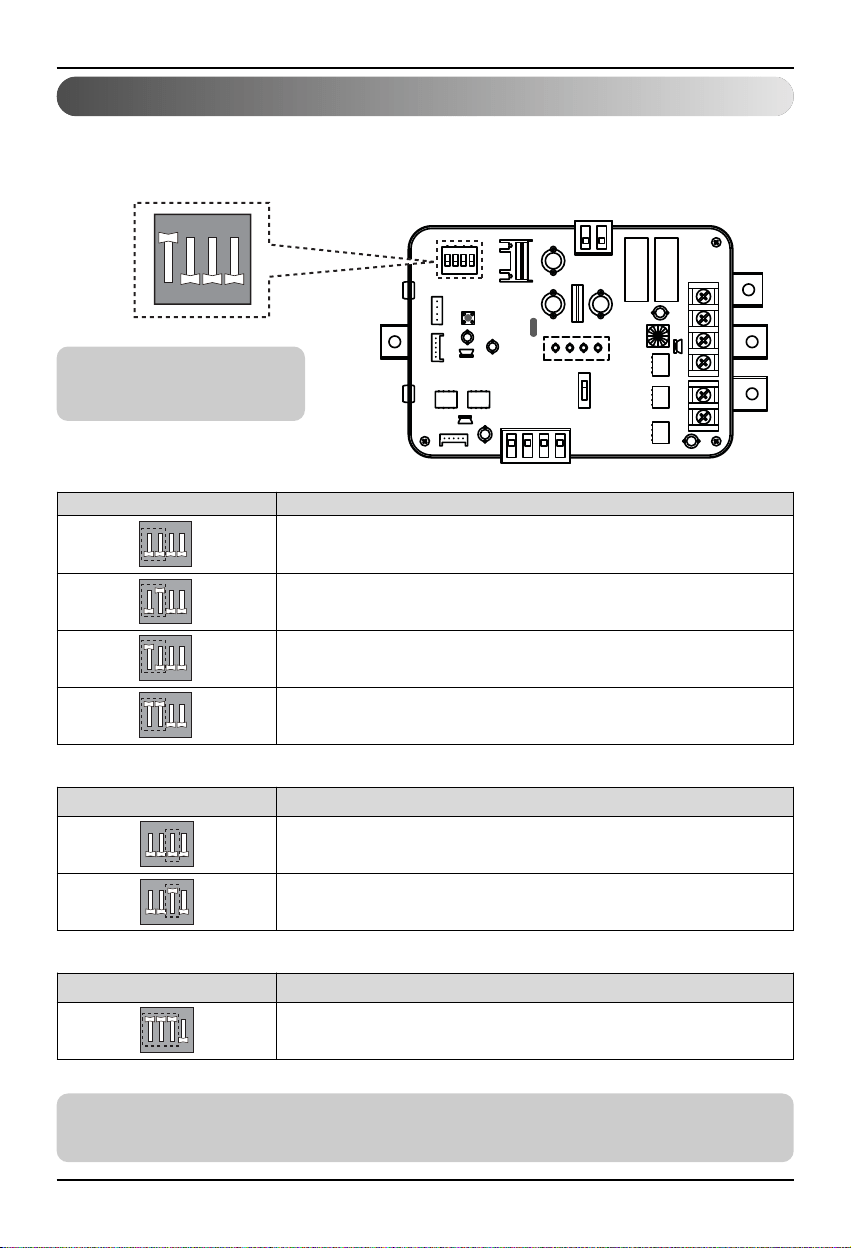
4. Setting of ‘SWDIP’
■ Using ‘SWDIP’, select the option of control function as
described below
ON
1234
Notes
Default status is L1 : ON
L2 : OFF
Position Function
Control signal : DC 0V(OFF), DC 8~10V(ON)
Control signal : DC 0V(OFF), DC 6~10V(ON)
Control signal : DC 0V(OFF), DC 4~10V(ON)
Default status
Control signal : DC 0V(OFF), DC 2~10V(ON)
ON
1234
ON
1234
ON
1234
ON
1234
• Output signal setting
Position Function
RS-485 communication function enable
RS-485 communication function disable
ON
1234
ON
1234
• RS-485 communication function setting
Position Function
ON
1234
Low Ambient Kit Control Setting
• Low ambient kit setting
Setting and using method
Notes
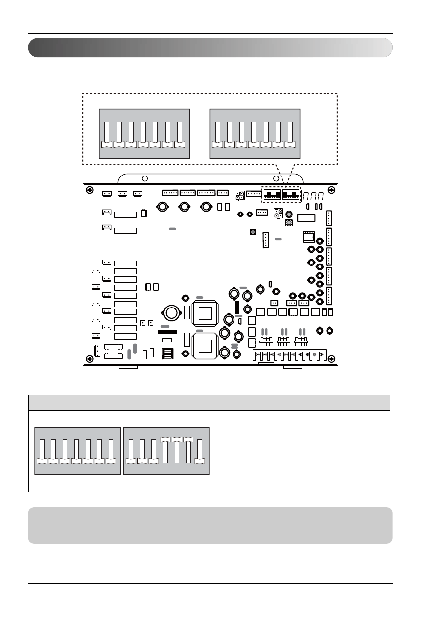
After change ‘SWDIP’ setting, then you must press reset switch to reflect the setting.
5. Setting of outdoor unit dip switch
Position Function
ON
1234567
ON
1234567
Low Ambient Control Mode
ON
SW01B SW02B
1234567
ON
1234567
22 Low Ambient Control Kit