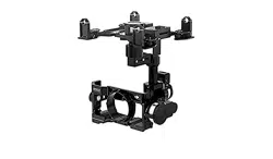
Zenmuse Z15-A7
2015.09
V1.2
User Manual

2
©
2015 DJI. All Rights Reserved.
Warning & Disclaimer
The Z15-A7 gimbal has been calibrated specically for the designated camera and lens before it leaves the
factory. Please mount only the designated camera and lens to the Z15-A7. Do not add any other component/
device (such as lters, etc.) to the camera. Please use the original camera battery, otherwise performance
may be hindered and internal malfunctions or damage may occur.
Only use the Z15-A7 gimbal with Flight Control Systems developed by DJI (such as the A2 or WooKong-M,
and please upgrade to the latest firmware) for the greatest stability and precision. Please download the
corresponding Assistant software and upgrade your Flight Control System’s rmware, otherwise the Z15-A7
may not function properly. When the main battery power is connected, please be careful and operate the
Flight Control System in the safest way possible. It is strongly recommended that you remove all propellers,
use the R/C or flight pack battery power system, and keep children away during gimbal calibration and
parameter setup. Carefully follow the appropriate steps to mount and connect the gimbal to your aircraft. Use
this manual as well as the related Assistant. Please respect the AMA’s National Model Aircraft Safety Code.
As DJI has no control over the use, setup, final assembly, modification (including use of non-specified
DJI parts i.e. motors, ESCs, propellers, etc.) or misuse, no liability shall be assumed nor accepted for any
resulting damage or injury. By the act of use, setup or assembly, the user accepts all resulting liability. DJI
assumes no liability for damage(s) or injuries incurred directly or indirectly from the use of this product.
DJI and Zenmuse are registered trademarks of DJI. Names of products, brands, etc., appearing in this
manual are trademarks or registered trademarks of their respective owner companies. This product and
manual are copyrighted by DJI with all rights reserved. No part of this product or manual shall be reproduced
in any form without the prior written consent or authorization of DJI.
Manual Tips
Legend
Important Tips
Designated Camera and Lens Type for the Z15-A7 Gimbal
Camera Type: Sony ILCE-7S, Sony ILCE-7R
Lens Type: Sony FE 35mm f2.8 ZA
Camera Battery Type for the Z15-A7 Gimbal: NP-FW50 (new version)
Ensure to use the new NP-FW50 battery for the Sony ILCE-7S and Sony ILCE-7R camera, which
has been produced by Sony after Jun 1, 2014. It is all black and weighs 40 g.
The Z15-A7 supports both Sony ILCE-7S and Sony ILCE-7R camera. It has been calibrated for the
Sony ILCE-7S camera by default. Balancing the tilt and pan axis is required if you are using the
Sony ILCE-7R on the Z15-A7.
Firmware versions of supporting DJI Flight Control Systems
WooKong M: V5.26 A2: V2.1 or above

©
2015 DJI. All Rights Reserved.
3
Contents
Warning & Disclaimer
2
Manual Tips
2
Product Prole
4
In the Box
5
Z15-A7 Diagram
7
Mount
8
Mounting the Sony ILCE-7S Camera 8
Mounting the Sony ILCE-7R Camera 8
Mounting the Gimbal to the Landing Gear 10
Video Signal Transmission
11
A. AV Wireless Video Transmission 11
B. DJI iOSD Mark II and AV Wireless Video Transmission 11
C. DJI Lightbridge Air System 12
D. DJI Lightbridge 2 13
GCU Wiring
15
GCU Wiring 15
GCU Ports 16
Working Mode/AUX2 Switch Setup
17
Working Mode Switch Settings 17
AUX2 Switch Settings 17
Shutter Control
18
Video Recording Control
18
PC Assistant Tuning
19
Installation and Usage 19
Basic Settings 19
Upgrade 20
Info 20
Pre-Flight Checklist
21
Pre-Flight Checklist 21
Flight Test 22
Appendix
23
Attention 23
1-Pilot Solution 23
2-Pilot Solution 24
Port Descriptions 25
Gimbal LED Indicator 25
Troubleshooting 26
Specications 27

4
©
2015 DJI. All Rights Reserved.
Product Prole
The Z15-A7 is a sophisticated gimbal specically designed for aerial creativity. It has a built-in independent
IMU module, special servo drive module, HDMI-HD/AV module, infrared remote control module, and more.
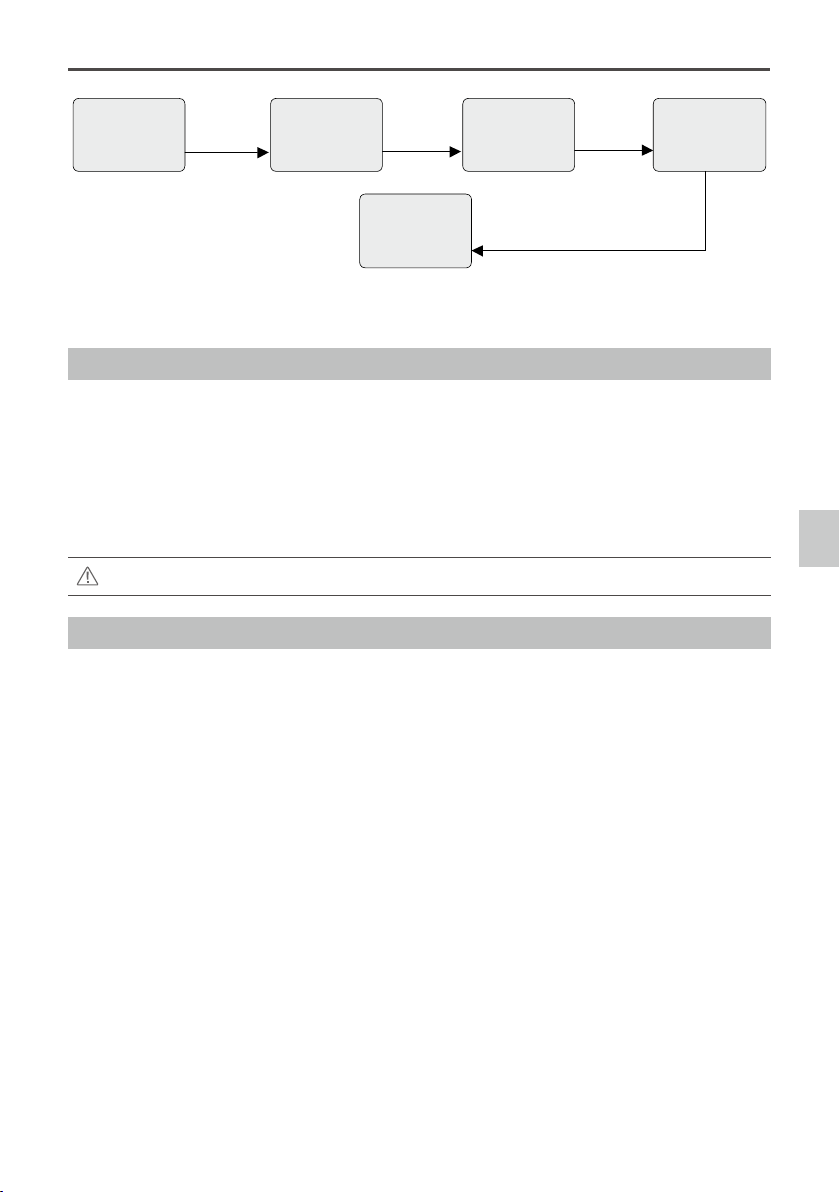
The Z15-A7 performs well in all modes, including Orientation-locked, Non orientation-locked, and FPV (Reset).
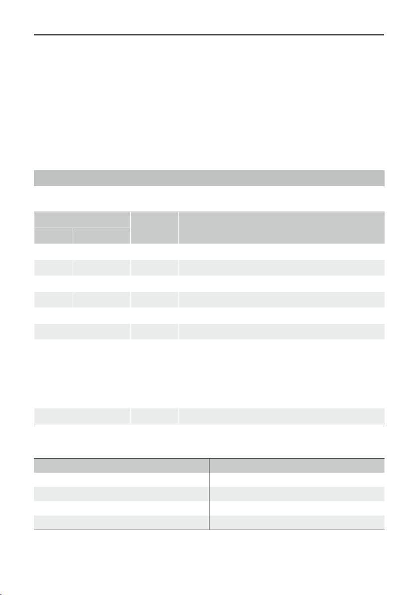
Working Modes
Orientation-locked Non orientation-locked FPV (Reset)
Gimbal
Direction
Gimbal pans with aircraft's nose.
Gimbal pan and
aircraft's nose move
separately.
Gimbal pan and
aircraft's nose are
synchronized.
Gimbal and
Aircraft's Nose
Relative Angle
The gimbal direction maintains the
same relative angle to the aircraft's
nose.
The relative angle
between the gimbal
direction and aircraft's
nose is controllable.
The relative angle
between the gimbal
direction and
aircraft's nose is 0°.
TX Control Controllable Controllable Uncontrollable
Attitude
Stability*
YES YES YES
Vibration
Reduction
YES YES YES
Stick
Movement
Denition
Roll is locked level in stick
commands from 0-2/3 and rotates
in commands from 2/3-endpoint;
Pan stick commands control the
rotation angle and are limited to
360
。
; Tilt stick commands control
the rotation velocity of the gimbal.
Stick commands for
gimbal rotation velocity
are relative to total stick
movement. The stick’s
center position velocity
is 0°/s. Its endpoint is
the maximum velocity.
——
Linear Control YES YES ——
Note*: Attitude stability means that the gimbal’s Roll/Tilt will not follow the aircraft’s Roll/Pitch movement.
Product Prole
©
2015 DJI. All Rights Reserved.
5
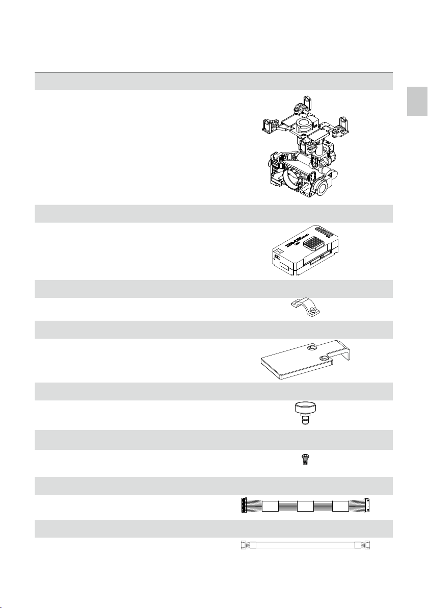
In the Box
Gimbal × 1
The Z15-A7 gimbal includes built-in servo drive
modules, an independent IMU module, an infrared
remote control module and a HDMI-HD/AV module.
Gimbal Controller Unit (GCU) × 1
Connect the GCU to your Flight Control System
using the CAN-Bus cable. The GCU will control the
gimbal’s pan, roll and tilt movements. Connect the
GCU to a video downlink for a video signal.
Mounting Bracket × 4
For mounting the gimbal to the landing gear.
Mounting Board for Receiver × 1
For attaching the GCU and providing a convenient
mount for the receiver or other devices.
Camera Mounting Screw × 1
A standard tripod mounting screw.
Screw Package × 1
For mounting the gimbal to your aircraft (M2.5*8 cap
head screw).
10-Pin to 9-Pin Cable × 2
For connecting the GCU to the gimbal.
7-Pin Cable × 1
For connecting the GCU to the Lightbridge air system.
In the Box
Zenmuse Z15-A7
User Manual
6
©
2015 DJI. All Rights Reserved.
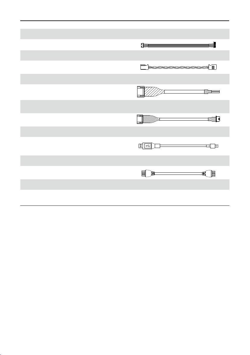
8-Pin to 6-Pin Cable × 2
For connecting the GCU to the gimbal.
Servo Cable Package × 1
For connecting the GCU and the receiver.
AV Video Power Cable × 1
For connecting the GCU and the wireless video
transmission module, and transmitting the AV signal.
iOSD Mark II Cable × 1
For connecting the GCU to the DJI iOSD Mark II.
Micro-USB Cable × 1
For adjusting parameters and upgrading rmware via
a PC.
CAN-Bus Cable × 1
For the CAN-Bus Flight Control System.
D J I
D J I
Spare Package × 1
Vibration Absorbers, Spare Screws, and Mounting
Bracket
©
2015 DJI. All Rights Reserved.
7
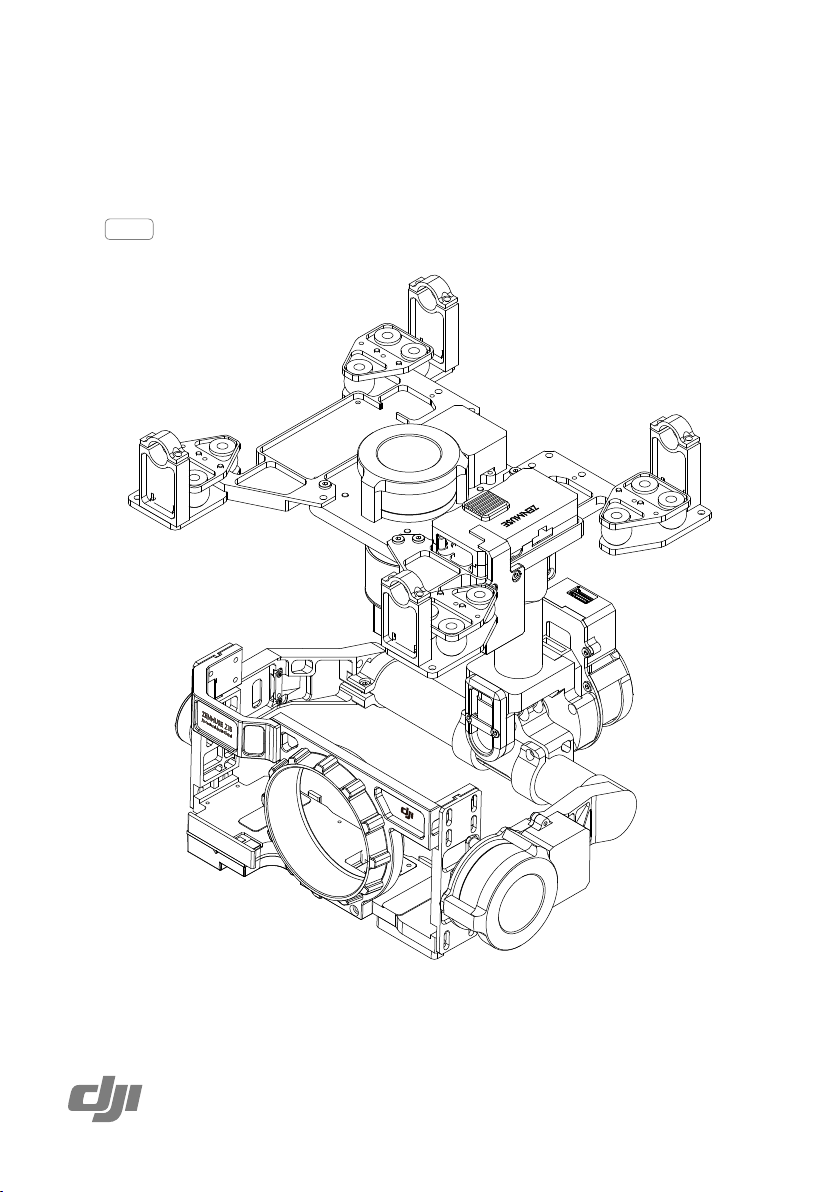
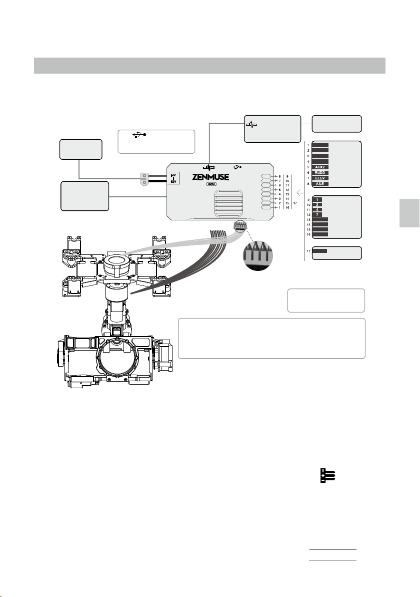
Z15-A7 Diagram
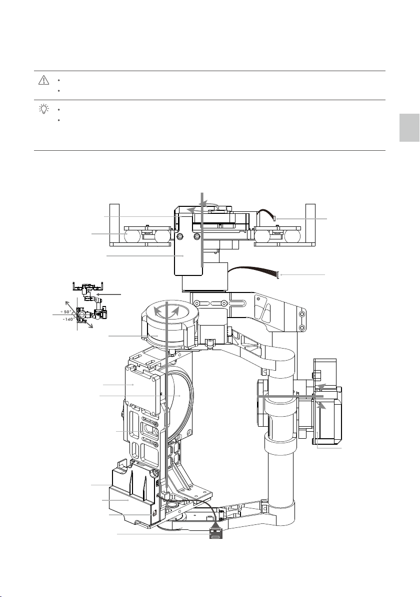
To avoid motor damage, ensure there is nothing blocking the rotation of the servo drive modules.
Clear obstacles or immediately cut off the power if any blockage occurs.
The servo drive modules have two motor command input ports and one private encoder port.
The HDMI-HD/AV module converts HDMI to HD (or AV) using a cable connected to the camera
HDMI port; it also transforms the TX signal to an infrared remote control module for shutter control
and video recording.
Motor lnput Port to
G6 Port of GCU
Servo Drive Module 1
Damping Unit
Receiver Mounting
Board
Servo Drive Module 3
IMU Module
Camera Mounting Holes
Gimbal LED
Indicator
HDMI-HD/AV Module
HD/AV Switch
HDMI Cable
Camera Mounting
Position
Tilt +50°/-140°
Arrow represents
the lens direction
Pan
±360°
Roll ±40°
Servo Drive
Module 2
9-Pin Port to G9
Port of GCU
Z15-A7 Diagram
8
©
2015 DJI. All Rights Reserved.
Mount
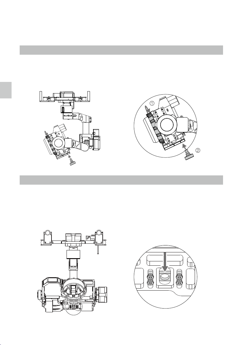
Power off the camera during the mounting process.
Mounting the Sony ILCE-7S Camera
1. Mount the camera onto the gimbal as shown and tighten the lens retaining ring.
2. Adjust the camera position and tighten the camera mounting screw.
Mounting the Sony ILCE-7R Camera
If you are using the Sony ILCE-7R camera on the Z15-A7, follow the steps below to mount the camera and
balance the tilt and pan axis.
1. Loosen the screws on the bottom of the gimbal of the positioning board. Slide the positioning board about
1 mm back as shown below and then tighten the screws.
Slide back 1mm
Mount
Zenmuse Z15-A7
User Manual
©
2015 DJI. All Rights Reserved.
9
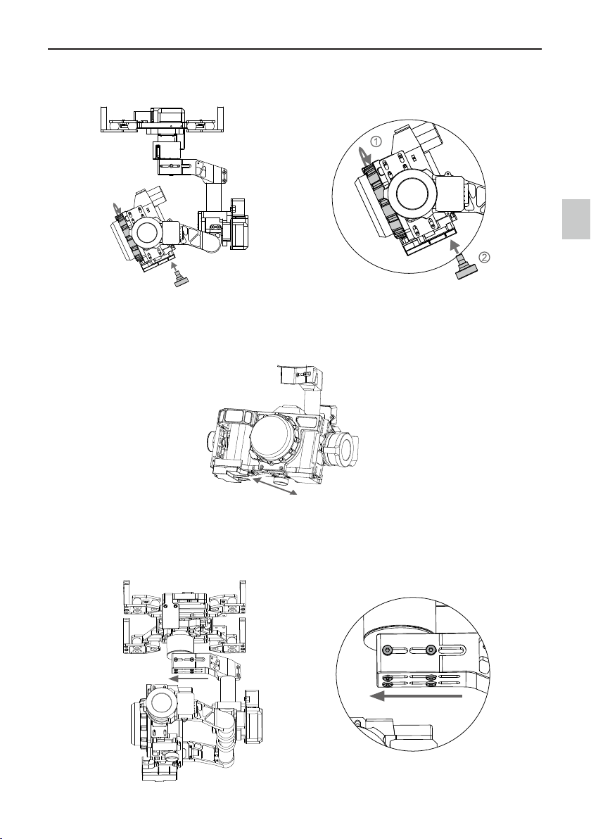
2. Mount the camera onto the gimbal as shown and tighten the lens retaining ring. Then tighten the camera
mounting screw.
3. Rotate the camera to any tilt angle, if it stays in position, then proper balance has been achieved.
Otherwise adjust the camera’s position by sliding the positioning board until the proper balance is
achieved.
4. Loosen the eight screws on the connection point of the pan axis. Then slide the pan axis forward about
0.5mm and tighten the screws. When the proper balance is achieved, the pan axis will stay in position after
rotating the gimbal 90 degrees. Balancing is complete.
Slide the pan axis forward about 0.5mm
Mount
Zenmuse Z15-A7
User Manual
10
©
2015 DJI. All Rights Reserved.
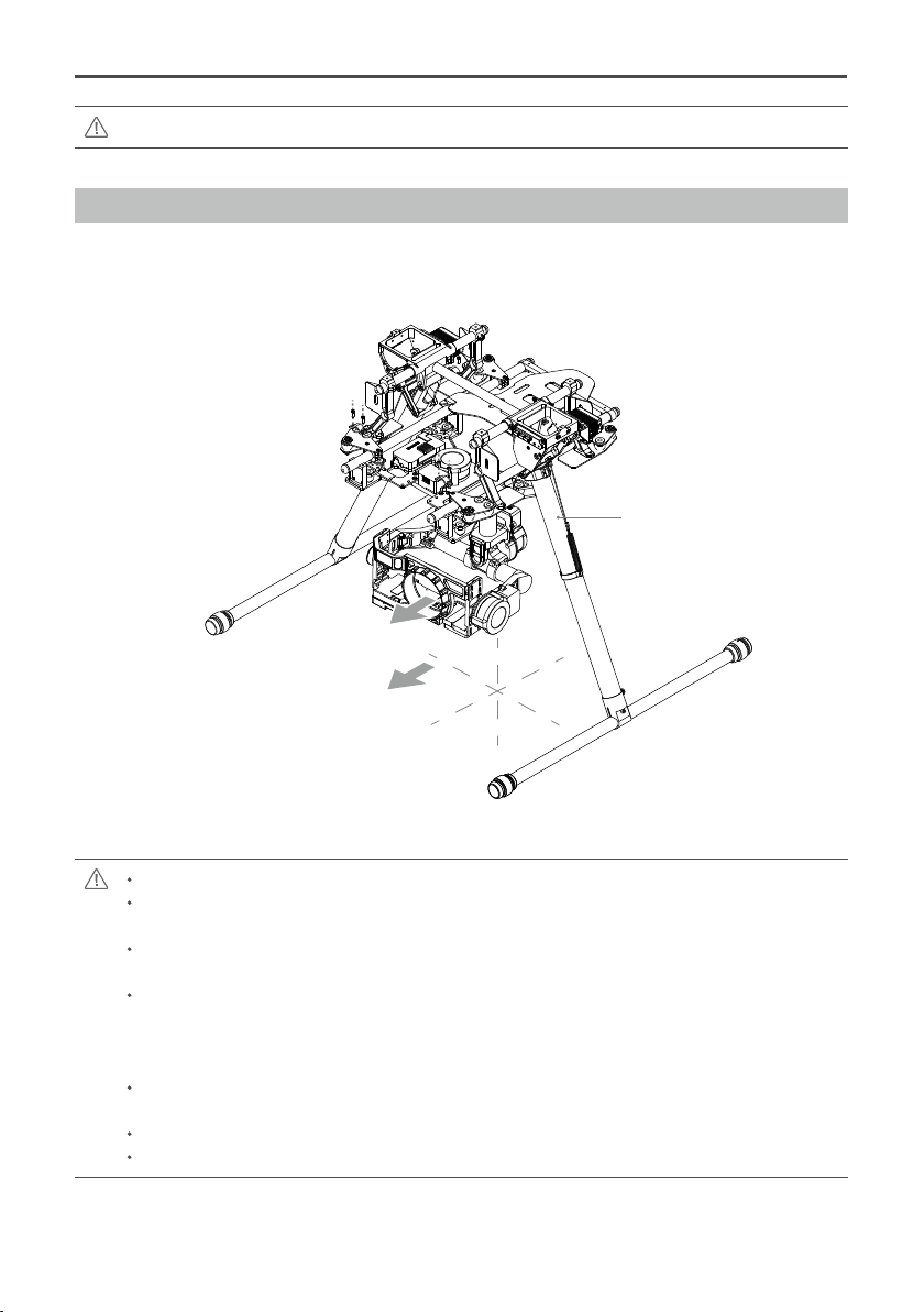
Ensure the lens is pointing in the same direction as the aircraft's nose.
Ensure the top and bottom plates of the damping unit stay parallel when mounting. This prevents
stretching and distortion.
Maintain good overall balance when mounting in order to ensure the center of gravity is balanced
on each of the three axis lines.
The gimbal’s center of gravity has been set by the factory. The center of gravity directly determines
the gimbal’s overall performance. Follow the instructions in this manual to adjust the center of
gravity if you are using the Sony ILCE 7R camera, otherwise do not adjust the gimbal’s center of
gravity.
The gimbal is highly precise and depends on this precision for optimal performance. Do not remove
any screws on the gimbal, as this may result in poor performance or damage to the gimbal.
Do not unplug any cables attached to the gimbal ports or change the mechanical structure.
Make sure the wiring is correct, otherwise the gimbal may behave abnormally.
X
Y
Z
S1000+ Landing Gear
Lens Direction
Aircraft's Nose Direction
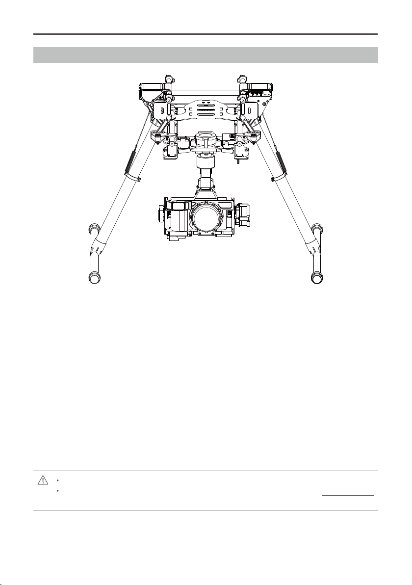
Mounting the Gimbal to the Landing Gear
The following diagram shows the gimbal mounted on a DJI S1000+. Mount the gimbal onto the landing gear
with the mounting brackets. Tighten the screws and use thread-locking uid.
You may also mount the gimbal onto different landing gear by referring to this diagram.
Whenever you test the gimbal, ensure all the screws on the gimbal are tightened.
©
2015 DJI. All Rights Reserved.
11
AV Video Power Cable
Wireless Video Transmission Module
Air Unit
Connect to the power source according to the
module’s voltage and current requirements.
ROLL
TILT
PAN
MODE
SHUT
AUX1
AUX2
AUX3
GCUGCU
1
Wireless Video
Transmission Module
Air Unit
Video Signal Port
G7
ROLL
TILT
PAN
MODE
SHUT
AUX1
AUX2
AUX3
GCUGCU
Yellow
Video Signal Port
G7
Power
Video Signal
GND
A7-HD
14V
52V
14V
52V
A7-HD
Video Signal Transmission
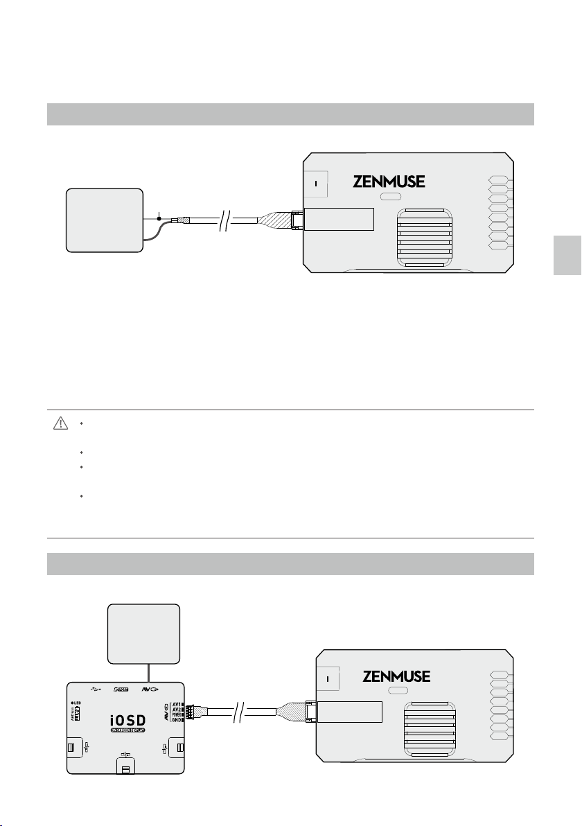
A wireless video transmission module is required for remote video.
A. AV Wireless Video Transmission
1. Solder the AV Video Signal and GND cables to the wireless video transmission module (Air Unit) as shown
above.
2. Plug the AV video power cable into the GCU’s G7 port.
3. Toggle the HD/AV Switch to the AV position. (See Page 7 for the location of the HD/AV Switch)
4. Power on the gimbal. If the gimbal LED indicator blinks yellow, it is functioning normally. If the LED indicator
shows a constant yellow light, the video signal is lost. Check the connections between the camera and the
HDMI video input.
Complete the connection between the wireless video transmission module and the GCU before
powering on the gimbal.
A standard AV video power cable is recommended.
Be sure to solder the AV video power cable to the wireless video transmission module correctly. As
the cable carries power, ensure the cables are insulated or wrapped to prevent a short circuit.
Connect the wireless video transmission module to a power source, as the GCU cannot supply
power. Make sure the power source provides a safe voltage for your own devices according to the
wireless video transmission module’s requirements.
B. DJI iOSD Mark II and AV Wireless Video Transmission
AV Video Power Cable
Wireless Video Transmission Module
Air Unit
Connect to the power source according to the
module’s voltage and current requirements.
ROLL
TILT
PAN
MODE
SHUT
AUX1
AUX2
AUX3
GCUGCU
1
Wireless Video
Transmission Module
Air Unit
Video Signal Port
G7
ROLL
TILT
PAN
MODE
SHUT
AUX1
AUX2
AUX3
GCUGCU
Yellow
Video Signal Port
G7
Power
Video Signal
GND
A7-HD
14V
52V
14V
52V
A7-HD
Video Signal Transmission
Zenmuse Z15-A7
User Manual
12
©
2015 DJI. All Rights Reserved.
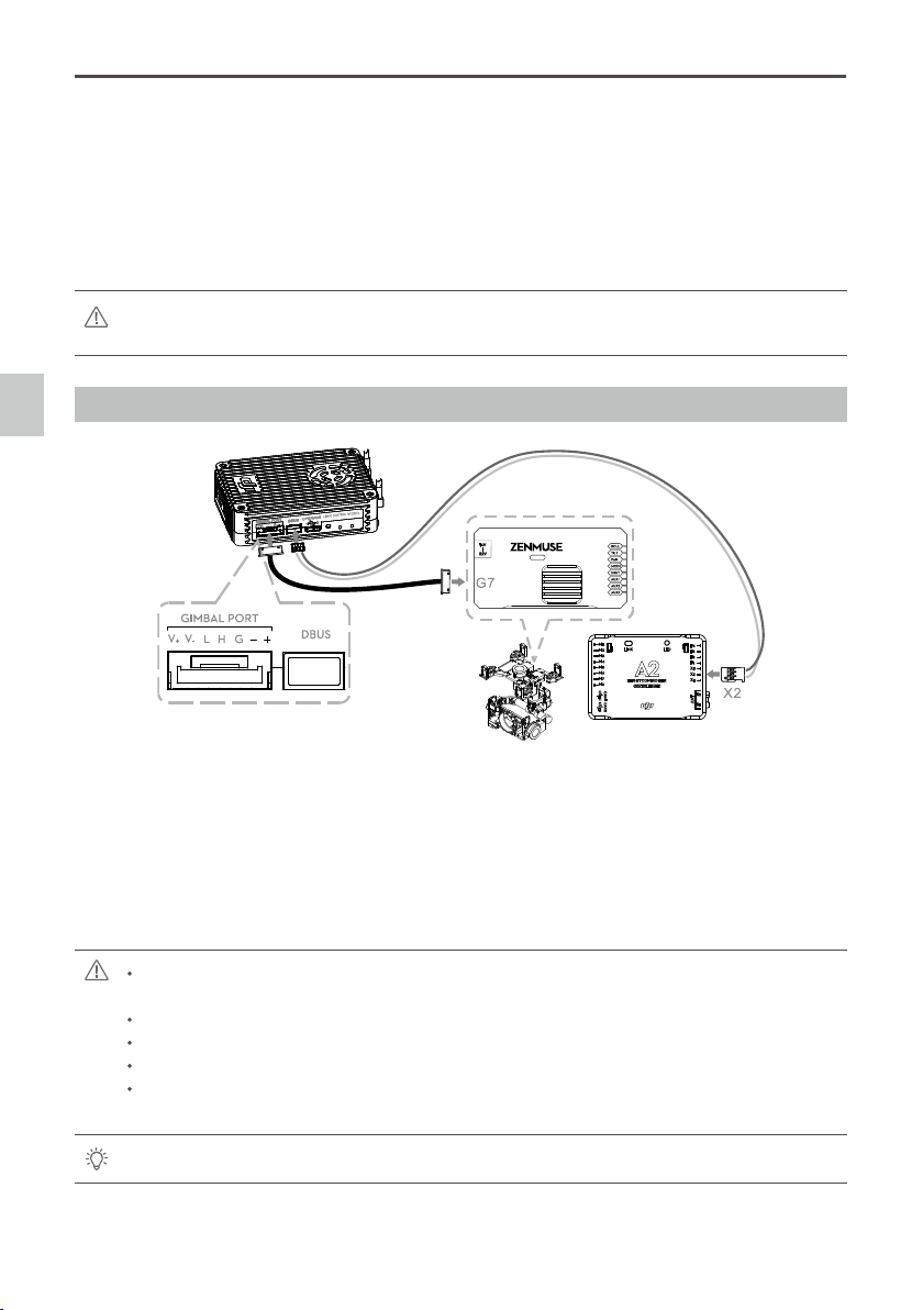
This example is based on a Z15-A7 gimbal and the A2 ight control system.
1. Connect the Gimbal Port on the Lightbridge Air System to the G7 port on the Z15-A7 GCU using the
supplied HD video power cable (7-pin cable).
2. Connect the DBUS port on the Lightbridge Air System to the DBUS port (X2 port) on the A2 ight control
system. Toggle the HD/AV switch to the HD position.
3. Refer to the Lightbridge and A2 ight control system manuals to complete the connection.
To transmit gimbal and aircraft signals, connect the RC receiver to the DJI Lightbridge ground
system when connecting the GCU.
Always connect the wireless video transmission module to the GCU before powering on.
A standard HD video power cable (7-pin cable) is recommended.
Complete the other connections according to the Lightbridge user manual.
If the gimbal LED indicator blinks red continuously, please power cycle the gimbal. (Power it off,
then power it back on)
If the video signal does not transmit, check each step.
1. Connect the iOSD Mark II cable to the GCU’s G7 port.
2. Complete the other connections between the iOSD Mark II cable and the wireless video transmission
module, according to their manuals.
3. Toggle HD/AV Switch to the AV position. (See Page 7 for the location of the HD/AV Switch)
4. Power on the gimbal. If the gimbal LED indicator blinks yellow, it is functioning normally. If the LED indicator
shows a constant yellow light, the video signal is lost. Check the connections between the camera and the
HDMI video input.
Make sure to connect the wireless video transmission module and the iOSD Mark II cable to the GCU
before powering on.
C. DJI Lightbridge Air System
GCUGCU
A7
HD
-
Video Signal Transmission
Zenmuse Z15-A7
User Manual
©
2015 DJI. All Rights Reserved.
13
Camera
HDMI
HDMI signal
HDMI-HD/AV cable
HD/AV signal
Monitor
Input
Gimbal
7-Pin Cable
Self-prepared by user
Wireless video
transmission module
Air unit
Wireless signal
5.8G/2.4G/1.2G
Ground unit
Wireless video
transmission module
10-Pin to 9-Pin Cable
HD/AV signal HD/AV signal
GCU
G9 G7
Video Signal Transmission
The following diagram shows how a video signal is transmitted from the gimbal.
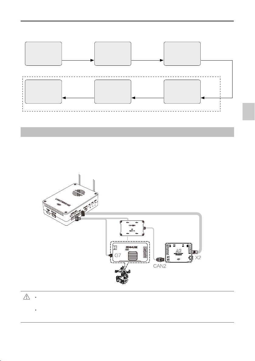
D. DJI Lightbridge 2
Connect the system as follows:
1. Connect the G7 port on the DJI HD gimbal and the CAN BUS port on the ight controller to the gimbal port
on the Air System.
2. Connect the X2 DBUS port on the ight controller to the DBUS port on the Air System.
3. Refer to the user manuals for the gimbal and ight controller for details.
DBUS Cable
Gimbal Cable
Only use the DJI HD gimbal and DJI ight controller with the latest rmware. The GCU rmware for
the HD gimbal must be v2.6 or above.
If you are using the DJI A2 Flight Controller, connect the gimbal cable to the CAN 2 port on the ight
controller.
Zenmuse Z15-A7
User Manual
14
©
2015 DJI. All Rights Reserved.
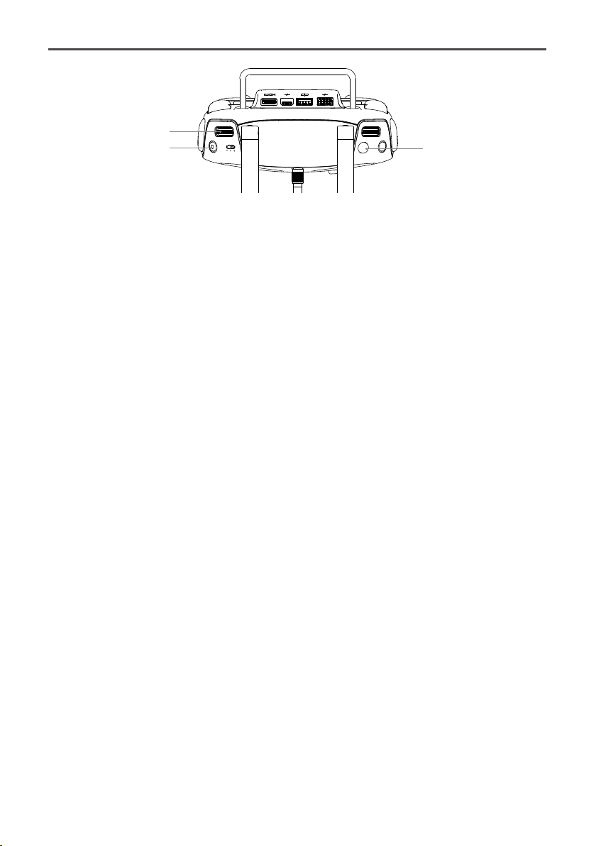
Press the shutter button [1] on the Ground System to capture photos. Press the record button [2] to record
video. Turn the Gimbal Dial [3] to adjust the tilt motion of the camera.
In Dual Ground System Mode, the pan, tilt or roll motion of the camera can be controlled by the Slave
Ground System, depending on your settings in the DJI GO app. Refer to the Lightbridge 2 User
Manual for details.
[1]
[3]
[2]
©
2015 DJI. All Rights Reserved.
15
GCU Wiring
GCU Wiring
The gimbal should be used with an A2 or WooKong-M ight control system. The GCU wiring is based on
WooKong-M. For WooKong-M, connect to any spare CAN-Bus port on the ight control system via a CAN-
Bus cable.
Battery
Connect the XT60 connector to the GIMBAL on the center frame if a S1000+ used.
Attention: Be aware that the S1000+ power supply voltage should be within the defined
limits (6S), even when using one battery for both S1000+ and Gimbal power supply.
Refer to S1000+ User Manual for details.
Turn to the next page to obtain the
corresponding channels between the
GCU channels and S-Bus receiver.
ROLL
TILT
PAN
MODE
SHUT
AUX1
AUX2
AUX3
WooKong-M
•
•
•
S-Bus
2-Position Switch
2-Position Switch
3-Position Switch
2-Position Switch
2-Position Switch
2-Position Switch
3-Position Switch
2-Position Switch
USB Port
PC connection for configuration and
firmware upgrades with an USB cable.
Ensure the side with copper contacts is
facing upward towards the heat sinks.
RC Receiver
(Aircraft control)
Battery
(4S~12S)
Wireless Video
Transition Module
Air Unit
RC Receiver
(JR)
8 Channels
RC Receiver
(Futaba/Hitec)
8 Channels
S-BUS Receiver
(Futaba)
OR
OR
G7
G9
G6
A7-HD
WooKong-M
Please refer to your WooKong-M User Manual for all connection and conguration details.
Gimbal Control Unit (GCU)
1. Make sure all ports are accessible when installing your MC so as to facilitate wiring and software conguration.
2. In 3-pin ports, the pins near the nicks are the signal pins.
3. Use the 6-pin cable for the G6 port, and the 10-pin to 9-pin cable for the G9 port.
4. DO NOT cover the heat sinks, and keep them unobstructed at all times.
5. The GCU module is NOT water or oil proof.
RC Receiver
1. The diagram on the previous page shows example connections. The aircraft signal will transmit through
the DJI Lightbridge ground system. After connecting to Lightbridge, it is not necessary to connect with an
RC receiver.
2. Prepare 2 TXs, one for gimbal control, and the other for aircraft control. Refer to the 2-Pilot Solution for more
details. If only one receiver is used for both aircraft and gimbal control, refer to the 1-Pilot Solution for more
GCU Wiring
Zenmuse Z15-A7
User Manual
16
©
2015 DJI. All Rights Reserved.
details.
3. Setup the Aileron, Elevator, and Rudder channels on the gimbal control TX. The command stick will control
gimbal rotation velocity. The center position is 0, and the end point is maximum velocity in both clockwise
and counter clockwise directions. (The end point is 100%)
4. Choose one 3-position switch/channel to use as the Z15-A7 Working Mode switch. (MODE)
5. Choose one 2-position switch/channel to use as the camera shutter control switch (SHUT), and another
2-position switch to use as the camera lens orientation switch in Reset Mode (AUX2).
6. Choose one 2-position switch/channel to use as the camera video recording control switch (AUX3).
7. Please refer to the Wookong-M User Manual for aircraft control settings.
8. Connect the receiver to the GCU correctly.
GCU Ports
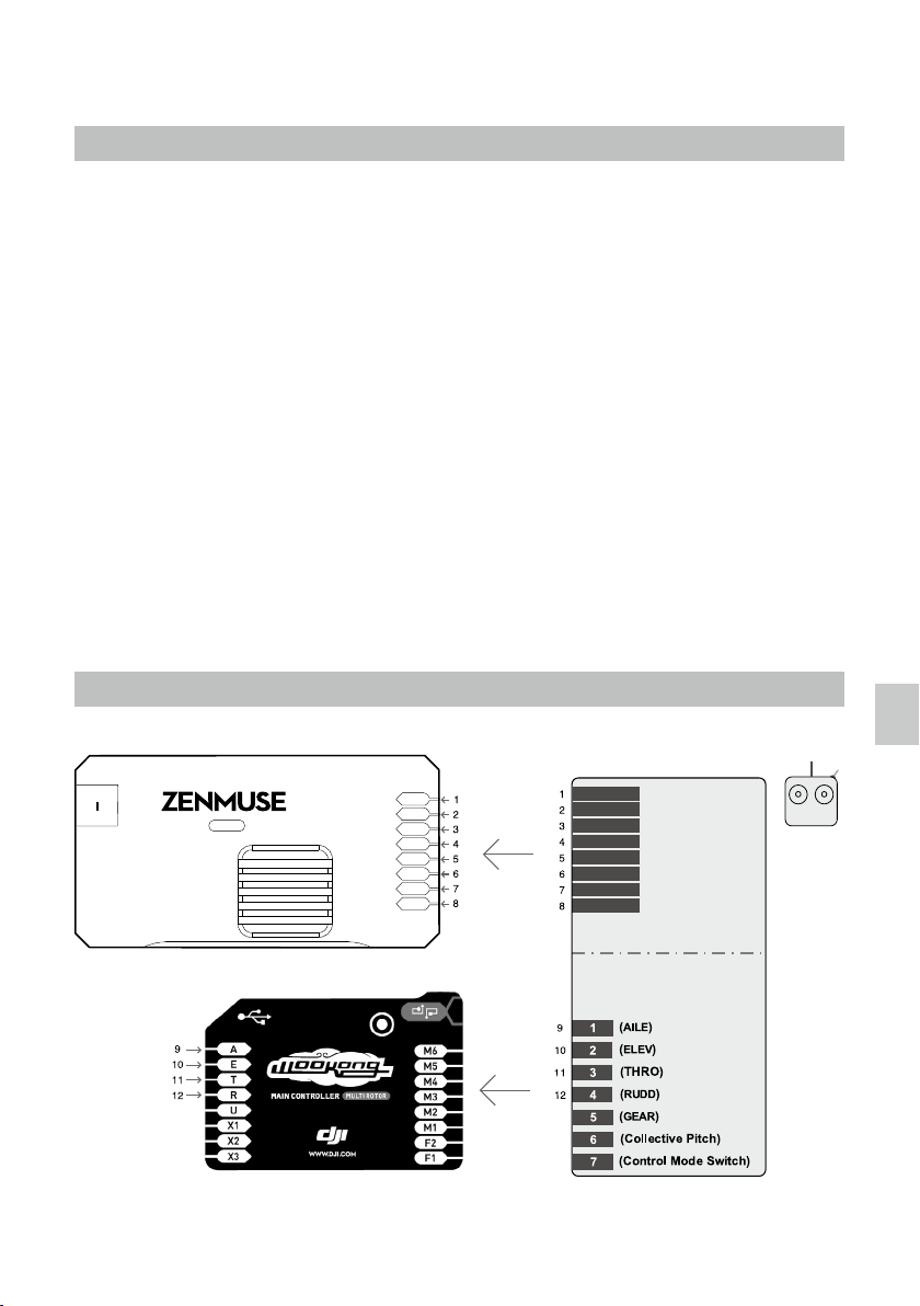
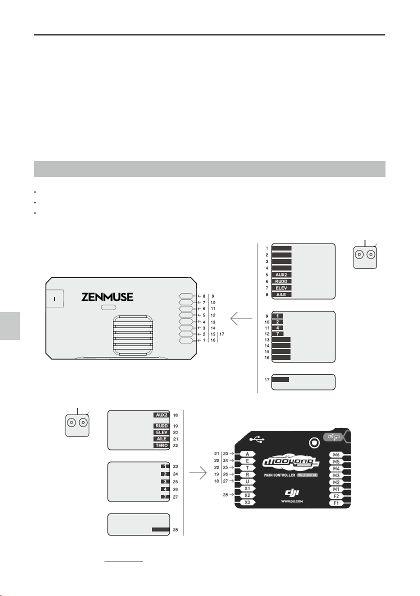
The following table shows the connections between the GCU channels and the relevant TX channels.
TX Channels
GCU Chan-
nels
Indications
JR Futaba/Hitec
AILE 1 ROLL For roll axis control (left/right). Velocity is zero if disconnected.
ELEV 2 TILT For tilt axis control. Velocity is zero if disconnected.
RUDD 4 PAN For pan axis control. Velocity is zero if disconnected.
AUX2 7 MODE For Working Mode switch.
2-position switch channel SHUT For camera shutter control.
2-position switch channel AUX1 Reserved channel.
Or Futaba S-Bus channel AUX2
When AUX2 is connected to a 2-position switch channel, it
is used as a camera orientation (down or forward) switch
in FPV Mode (Reset). The camera orientation is forward if
disconnected.
Or if you are using a S-Bus receiver, connect the recever to
the AUX2 port.
2-position switch channel AUX3 For camera video recording control.
The following table shows the corresponding relationship between the GCU and the S-Bus channels.
S-Bus Channels GCU Channels S-Bus Channels GCU Channels
1 ROLL 5 SHUT
2 TILT 8 AUX1
4 PAN 9 AUX2
7 MODE 6 AUX3
©
2015 DJI. All Rights Reserved.
17
Working Mode/AUX2 Switch Setup
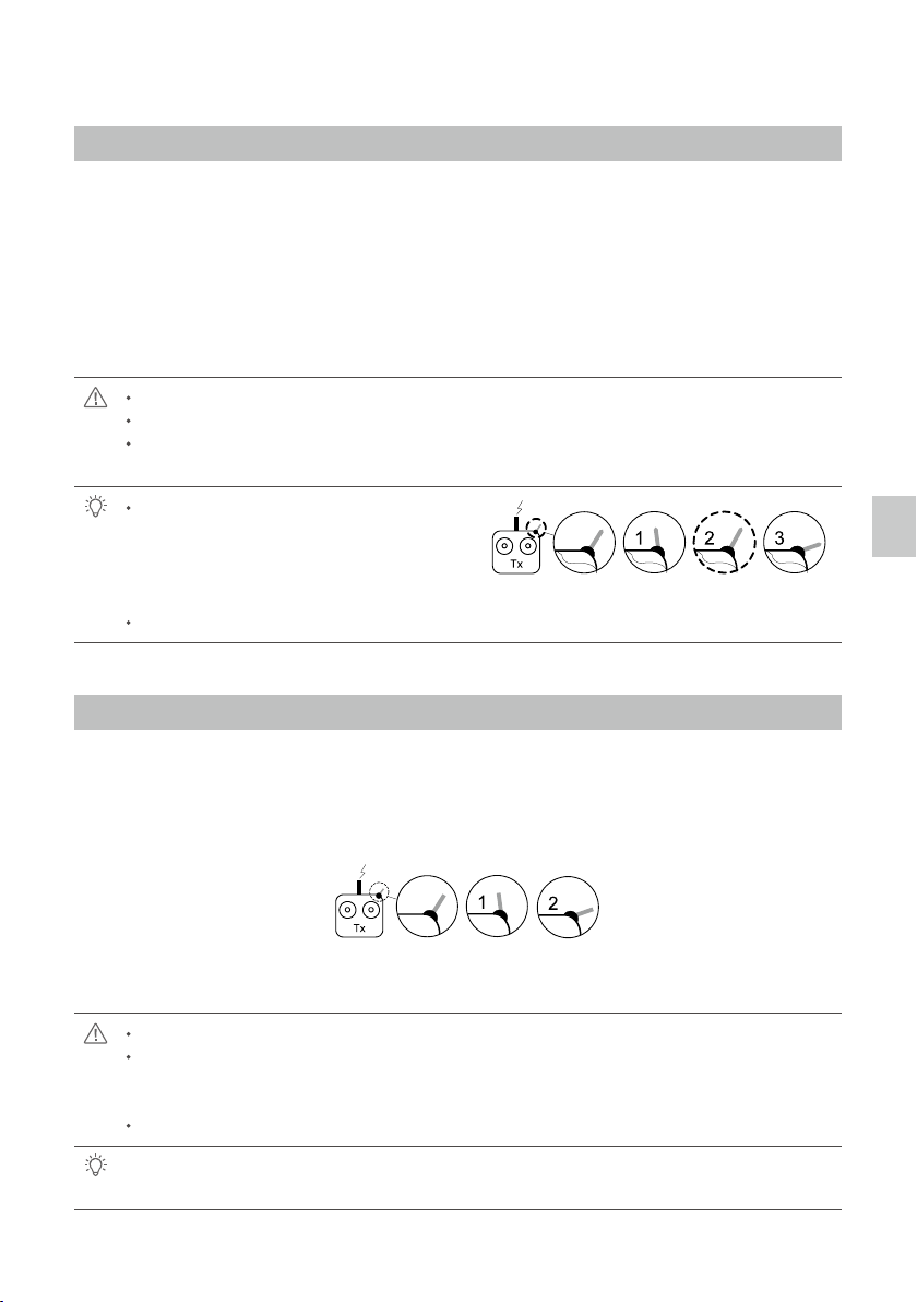
Working Mode Switch Settings
For whichever 3-position switch you select to use as the Working Mode switch, wire the relevant channel from
the receiver to the MODE port. At each switch position, use end-point ne tuning to set a channel AUX2 (JR)
or 7 (Futaba/Hitec) for all three Working Modes:
Orientation-locked Back to center
FPV (Reset) MODE channel end-point 60%~90%
Non orientation-locked MODE channel end-point 60%~90%
The gimbal will work in Orientation-locked mode if the MODE channel is disconnected.
FPV mode is the default startup mode when the MODE channel is connected.
The Working Mode from the previous power cycle will be retained if the cable between MODE and
the RC receiver is disconnected during operation.
For a 3-position switch, you may assign:
2-Positon
Switch
3-Positon
Switch
3-Positon
Switch
Position-1 to Non orientation-locked
Position-2 to Orientation-locked
Position-3 to FPV Mode (Reset)
Position-1 and Position-3 can be inversely assigned.
One 2-position switch can be assigned for any two of the working modes, if preferred.
AUX2 Switch Settings
The Z15-A7 supports toggling the camera lens down or forward in FPV Mode (Reset). Please choose a
2-position switch for this function and wire the relevant channel of the receiver to the AUX2 port. You may
assign: Position-1 to DOWN; Position-2 to FORWARD; or reverse the assignment.
2-Positon
Switch
3-Positon
Switch
3-Positon
Switch
This function will only work in FPV Mode (Reset).
When this function is active, if the Working Mode is ever changed to FPV Mode (Reset), the gimbal
will force the camera lens to face forward or down, depending on current the location of the AUX2
switch.
The camera orientation is forward if AUX2 is disconnected.
If AUX2 is connected to a Futaba S-Bus channel, it is then used as the input channel for S-Bus
control.
Working Mode/AUX2 Switch Setup
18
©
2015 DJI. All Rights Reserved.
If the shutter control does not work correctly, please check each step.
The following diagram shows how the shutter control works.
2-Positon
Switch
3-Positon
Switch
3-Positon
Switch
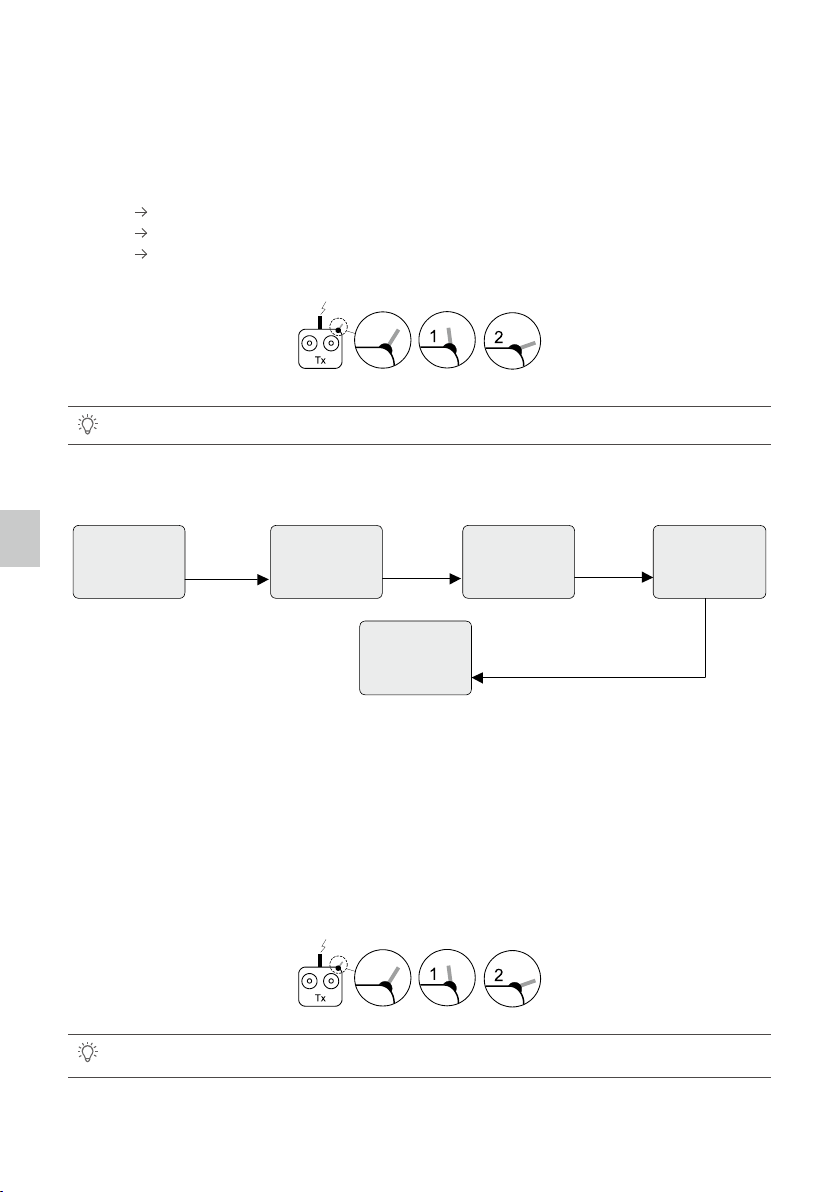
Shutter Control
The Z15-A7 gimbal can transform a TX command into a shutter control signal. Select a 2-position switch/
channel to use for remote shutter control.
For whichever 2-position switch you select, connect the correct receiver channel to the SHUT port. Toggling
the 2-position switch works as follows:
Position-1 Position-2: Take one photo
Position-2 Position-1: Reset switch position (no shutter effect or action)
Position-1 Position-2: Take another photo
Video Recording Control
The Z15-A7 supports starting and stopping your camera’s video record function by using a 2-position switch
through AUX3. Connect the relevant channel of the receiver to the AUX3 port. Toggle the switch to start/stop
recording.
Position-1: Start recording
Position-2: Stop recording
If the video recording control does not work correctly, please check each step.
The following diagram shows how the shutter control works.
2-Positon
Switch
3-Positon
Switch
3-Positon
Switch
TX
2-Position Switch
TX Command TX Command TX Command
Wireless
RC Receiver
3-Pin Cable
Internal Cable
HDMI-HD/AV
Module
Gimbal
Camera
GCU
Shutter Button
2-Position
Switch Channel
SHUT
Infrared Remote Control
Shutter Control/Video Recording Control
Zenmuse Z15-A7
User Manual
©
2015 DJI. All Rights Reserved.
19
PC Assistant Tuning
Installation and Usage
1. Ensure the most recent drivers are installed correctly. This should be done before using the A2 or
WooKong-M software.
2. Download the appropriate Assistant installer from DJI.com.
3. Double click the Assistant installer and follow the steps to nish the installation.
4. Run Assistant.
5. Upgrade the rmware or congure parameters using Assistant as needed.
The Assistant installer can be used on Windows XP, Win7, and Win8 (32 or 64 bit).
Basic Settings
You can set transmitter channels for roll, tilt and pan control, and also switch between working modes
during ight. Move your cursor to each area or refer to this manual for more details.
TX
2-Position Switch
TX Command TX Command TX Command
Wireless
RC Receiver
3-Pin Cable
Internal Cable
HDMI-HD/AV
Module
Gimbal
Camera
GCU
Shutter Button
2-Position
Switch Channel
SHUT
Infrared Remote Control
PC Assistant Tuning

Zenmuse Z15-A7
User Manual
20
©
2015 DJI. All Rights Reserved.
Upgrade
You can view the latest rmware version information on this page. Upgrade the rmware by following the
steps below:
1. Connect the gimbal to your computer with a Micro-USB cable, and wait until the blue indicator LED in the
Assistant is blinking.
2. Click” Upgrade”.
3. Wait for the download to nish.
4. Click “Upgrade” again then click “Conrm”.
5. Power cycle the gimbal after the upgrade is complete.
Ensure your computer is connected to the internet.
Close any antivirus programs and network rewalls during the upgrade.
Ensure the gimbal is powered on during the upgrade.
Do not disconnect the USB cable during the upgrade.
Make sure that before turning on the gimbal it already has a camera mounted.
Make sure there are no obstructions when turning on the gimbal.
Info
You can check the Assistant version via Info.
S/N is a 32 digit authorization code for function activations. The authorization code for your unit is lled in at
the time of manufacture. In the future, you may be asked to ll in a new S/N if you require function upgrades.
Fill in the S/N and then click the Write button. If you ll in an invalid S/N more than 30 times, your gimbal will be
locked and you will have to contact DJI customer support.
Zenmuse Z15-A7
User Manual
©
2015 DJI. All Rights Reserved.
21
Pre-Flight Checklist
Pre-Flight Checklist
Ensure the gimbal is properly installed and attached to the landing gear, and that the camera is
mounted correctly and securely.
Before powering on, spin the gimbal through its complete rotation by hand on each axis to ensure
nothing is blocking its movement.
Ensure all cables are connected correctly, without any plugged in backwards or into the wrong
ports.
Ensure the AV video power cable is properly soldered and shielded if an AV video transmission
module is used.
Verify TX settings.
Verify a proper connection between the GCU and the RC receiver.
Verify a proper connection between the GCU and the ight control system.
Ensure the latest Flight Control System rmware is installed.
Refer to the Gimbal LED Indicator section in the Appendix to understand the connection status
between the camera and gimbal.
Refer to the Troubleshooting section in the Appendix if an abnormal situation occurs.
Pre-Flight Checklist
Zenmuse Z15-A7
User Manual
22
©
2015 DJI. All Rights Reserved.
Flight Test
1. Ensure the batteries are fully charged for your TX, GCU, and all of the other devices on your aircraft.
2. Make sure all connections and wiring are in good condition.
3. Switch on the TX.
4. Adjust the camera to a level position on the roll axis of the gimbal.
5. Power on the gimbal and wait for the self initialization test to complete. The roll, pan and tilt axis will rotate
quickly at the same time.
6. After self-initialization, the camera lens will point towards the aircraft’s nose and each axis of the gimbal
should be in the position illustrated above.
7. The gimbal will then go into a second stage of initialization. At this time, each axis will rotate very slowly.
8. Once each axis stops moving, the gimbal is fully initialized and ready to use.
9. Toggle the assigned Working Modes switch on your TX and make sure it is working properly.
10. Switch the Working Modes to Non orientation-locked, FPV Mode (Reset), and Orientation-locked Mode
respectively. Then push the controller sticks lightly in the Roll, Tilt and Pan directions to check that the
gimbal moves in the corresponding directions. If not, see Working Mode/AUX2 Switch Setup to correct
your settings.
Power off the camera during the initialization.
If the gimbal does not match the diagram after initialization, please refer to the Troubleshooting
section in Appendix.
©
2015 DJI. All Rights Reserved.
23
Appendix
Attention
For safety reasons, please pay careful attention to all of the following items:
1. To avoid motor damage, ensure nothing blocks the servo drive module’s total range of movement.
2. Before powering on, spin the gimbal through its complete rotation by hand on each axis to ensure nothing
is blocking the mechanical movement of the gimbal.
3. Be sure to mount the side of servo drive module 1 with the ports facing towards the aircraft's tail.
4. The gimbal’s center of gravity has been preset. The gimbal balance is directly related to its performance.
Follow the instructions in this manual to adjust the center of gravity if you are using the Sony ILCE 7R
camera, otherwise do not adjust the gimbal’s center of gravity.
5. The gimbal is a sophisticated device. Do not remove any screws from the gimbal. Doing so may result in
poor performance or damage.
6. Do not unplug any cables attached to the gimbal ports or change the mechanical structure.
7. Make sure all wiring is correct, otherwise the gimbal may not operate correctly or efciently.
8. Make sure to connect the wireless video transmission module to the GCU prior to powering on the system.
9. We recommend use of the included AV video power cable, if needed.
10. Be sure to solder the AV video power cable to the wireless video transmission module correctly. Ensure
the cables are insulated and protected to prevent any type of short circuit.
11. Pay close attention to the voltage of S1000+ and be sure it is within the dened limits (6S) when using
one battery for both the S1000+ and as a power supply for the gimbal.
12. Never touch the contact points of a power cable to the gimbal, this may lead to a short circuit of the
gimbal, resulting in complete failure.
13. Before powering on, adjust the roll axis of the gimbal to be level.
1-Pilot Solution
14V
52V
Flight Controller(DJI WooKong-M)
GCUGCU
ROLL
TILT
PAN
MODE
SHUT
AUX1
AUX2
AUX3
Gimbal Control Unit(GCU)
3-Position Switch
3-Position Switch
3-Position Switch
3-Position Switch
2-Position Switch
2-Position Switch
2-Position Switch
3-Position Switch
14 Channels Receiver(Futaba)
Gimbal Control
Flight Control
Transmitter
A7
HD
-
Appendix
Zenmuse Z15-A7
User Manual
24
©
2015 DJI. All Rights Reserved.
1. Prepare one 14-channel TX/RC receiver for the aircraft and gimbal control. Above is an example of the
wiring conguration.
2. Setup the Aileron, Elevator, Throttle, and Rudder channels on your TX for aircraft roll, elevator, throttle, and
rudder control. Also, connect the TX’s AUX2 for aircraft control modes (Please refer to your Flight Control
System’s user manual).
3. Choose three 3-position switches to use for the gimbal Roll, Tilt, and Pan rotation control. The center
position of each switch is 0 velocity, and the end point positions are maximum velocity.
4. Choose one 3-position switch/channel as the gimbal’s Working Modes switch (MODE).
5. Choose one 2-position switch/channel as the camera shutter control switch (SHUT).
6. Connect the receiver to the GCU and Flight Control System correctly.
2-Pilot Solution
OR
OR
S-Bus
GCUGCU
ROLL
TILT
PAN
MODE
SHUT
AUX1
AUX2
AUX3
RC Receiver A
Gimbal Control Unit(GCU)
Transmitter A
Gimbal Control
Flight Controller
RC Receiver B
RC Receiver
(JR)
8 Channels
RC Receiver
(JR)
8 Channels
S-Bus
Transmitter B
OR
OR
DJI WooKong-M Flight Controller
RC Receiver
(Futaba/Hitec)
8 Channels
RC Receiver
(Futaba/Hitec)
8 Channels
S-BUS Receiver
(Futaba)
S-BUS Receiver
(Futaba)
2-Position Switch
2-Position Switch
3-Position Switch
2-Position Switch
2-Position Switch
2-Position Switch
3-Position Switch
2-Position Switch
14V
52V
A7
HD
-
Two transmitters and two receivers are required.
Transmitter A and receiver A are used to control the gimbal.
Transmitter B and receiver B are used to control the aircraft.
Make the connections as shown in the diagram below:
Please refer to the
GCU Wiring
section for more details.
Appendix
Zenmuse Z15-A7
User Manual
©
2015 DJI. All Rights Reserved.
25
Port Descriptions
GCU
ROLL For roll axis control
TILT For tilt axis control
PAN For pan axis control
MODE For working mode switch
SHUT For camera shutter control
AUX1 Reserved channel
AUX2 For gimbal orientation (down or forward) switch in FPV mode ; S-Bus receiver
AUX3 For video recording
G7
1. Connect to the wireless video transmission module, for transmitting AV
or HD signals.
2. Connect to DJI Lightbridge, for transmitting HD, gimbal and aircraft control
signals.
XT60 Connect to the battery (or to GIMBAL if DJI S1000+ is used)
G6 Connect to gimbal, for transmitting motor commands
G9 Connect to gimbal, for transmitting the video signal
Micro-USB port: for PC connection (Assistant conguration and rmware upgrades)
CAN-Bus port: Use CAN-Bus to connect GCU to the ight control system
Gimbal
HDMI-HD/AV Port To camera HDMI port
Motor Command Input Port To GCU G6
10-Pin to 9-Pin Cable Port To GCU G9
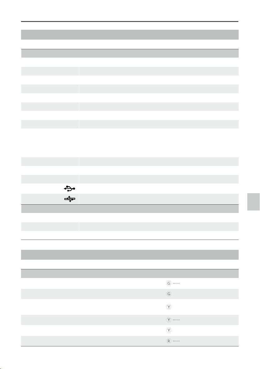
Gimbal LED Indicator
Description LED Indicator
HD mode, HDMI-HD/AV module transmits normally
LED is blinking green.
HD mode, without camera HDMI video input
Green LED is constant on.
HD mode, DJI Lightbridge App video source has been set
to “HDMI/AV”
Yellow LED is constant on.
AV mode, HDMI-HD/AV module transmits normally
LED is blinking yellow.
AV mode, without camera HDMI video input
Yellow LED is constant on.
HD video transmission module and gimbal is disconnected
LED is blinking red.
Appendix

Zenmuse Z15-A7
User Manual
26
©
2015 DJI. All Rights Reserved.
Troubleshooting
NO. The Problem The Cause What to Do
1
The gimbal keeps drifting
after initialization.
(1) The TX trims are too high.
(2) The GCU and Flight
Control System have
been disconnected.
(3) The gimbal direction is
not pointing in the same
direction as the aircraft’s
nose.
(1) Adjust the TX trims.
(2) Connect the GCU and Flight
Control System.
(3) Ensure the gimbal direction is
pointing in the same direction
as the aircraft’s nose.
2
The gimbal is in an
incorrect position after
initializing.
Abnormal calibration after
manufacturing.
Please contact your local dealer
or DJI customer service.
3
Cannot distinguish the
gimbal’s direction when in
use.
BVR (Beyond Visual Range)
ight.
Switch to FPV Mode rst, then
to another Working Mode as
needed.
4
The gimbal LED is blinking
red.
(1) There is a disconnected
cable between the gimbal
and camera.
(2) The camera is off.
(3) Camera setup failure.
(1) Make sure all cables are
securely connected.
(2) Power on the camera.
(3) Set the HDMI resolution to
1080i.
5
The gimbal’s green or
yellow LED is continuously
on, but no video is
displayed.
(1) The HDMI-HD/AV
transmission module is
disconnected from the
camera.
(2) The camera is powered off.
(3) In HD mode, the DJI
Lightbridge App video
source has been set to
“HDMI/AV”.
(1) Check HDMI-HD/AV
transmission module
connection.
(2) Power on the camera.
(3) Change the DJI Lightbridge
App video source to "HD
Gimbal".
Appendix
Zenmuse Z15-A7
User Manual
©
2015 DJI. All Rights Reserved.
27
Specications
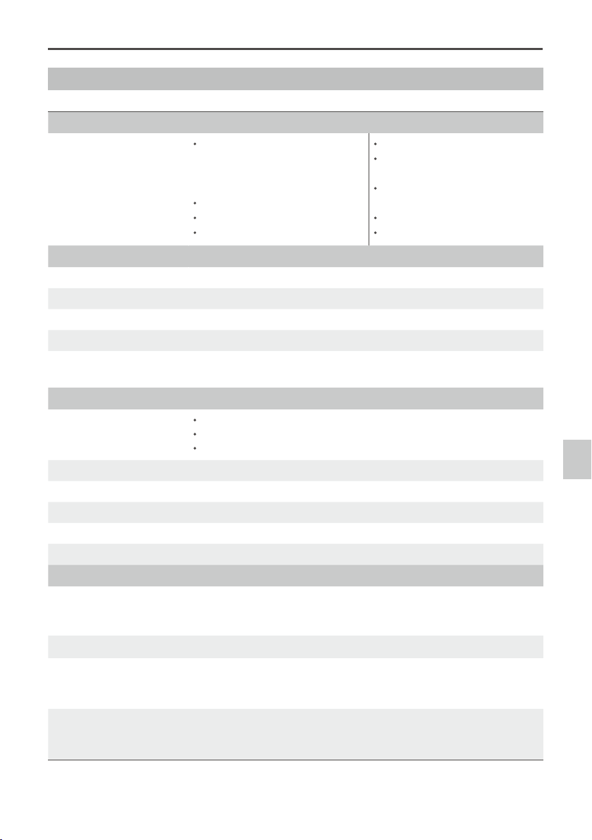
General
Built-In Functions Three Working Modes
Orientation-locked control
Non orientation-locked control
FPV mode (Reset)
Built-in independent IMU module
DJI gimbal special servos drive module
HDMI-HD/AV module
Infrared remote control module
Wireless video transmission
supported
Camera shutter/video recording
control supported
Wide range voltage input supported
S-Bus Receiver supported
Peripheral
Supported Camera Sony ILCE-7S; Sony ILCE-7R
Supported Lens Sony FE 35 mm f2.8 ZA
GCU Input Power 4S~12S LiPo (Recommend 6S if with S1000+)
Control Requirement At least four spare receiver channels
Assistant Software System
Requirements
Windows XP SP3; Windows 7; Windows 8 (32 or 64 bit)
Mechanical & Electrical Characteristics
Working Current Static current: 200mA (@25V)
Dynamic current: 400mA (@25V)
Locked-motor current: 4A (@25V)
Operating Temperature -10 °C ~ 50 °C
Weight 1.3 Kg
Dimensions 210 mm × 204 mm × 246 mm
GCU Weight 63 g
GCU Dimensions 64.2 mm × 34.1 mm × 19.5 mm
Working Performance
Load Weight (Reference Value)
622 g(@Sony ILCE-7S with Sony FE 35 mm f2.8 ZA, battery, lens hood and
SD Card) ; 580 g(@Sony ILCE-7R with Sony FE 35 mm f2.8 ZA, battery,
lens hood and SD Card)
Angular Vibration Range ±0.01°
Maximum Controlled
Rotation Speed*
Pan axis: ±130°/s
Tilt axis: ±130°/s
Roll axis: ±30°/s
Controlled Rotation Range Pan axis control: ±360° continuous rotation
Tilt axis control: +50°/-140°
Roll axis control: ±40°
Note*: Gimbal’s Maximum Controlled Rotation Speed corresponds to TX stick input pushed to 100% end-points.
Appendix

The content is subject to change.
Download the latest version from
http://www.dji.com/product/zenmuse-z15-a7
©
2015 DJI. All Rights Reserved.
If you have any questions about this document, please contact DJI
by sending a message to [email protected].