RF-SSVC4/RF-SSVC6 Speaker Selectors
QUICK SETUP GUIDE
ENGLISH 09-1150
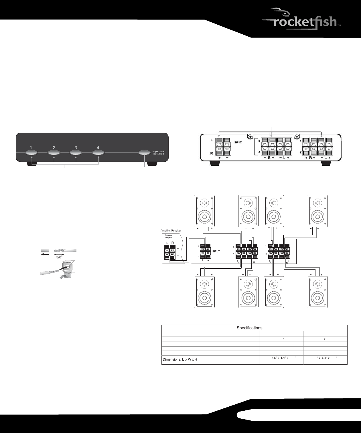
Zone buttons
1.97
1.97
12.8
(9.5 mm)
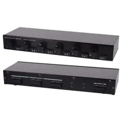
Left speaker (4)
Left speaker (3)
Right speaker (3) Left speaker (1)
Right speaker (1)
Right speaker (2)
Left speaker (2)
Right speaker (4)
Listening zones
Protection circuit resistors
Maximum amplier power with protection circuit engaged
Maximum amplier power with protection circuit not engaged
1 x 3 ohm/50 watts per channel 1 x 3 ohm/75 watts per channel
(216 x 112 x 50 mm)
(324 x 112 x 50 mm)
SSVC4 SSVC6
40 watts/channel
40 watts/channel
120 watts/channel
120 watts/channel
Push terminals
Impedance protection
Installation
1 Turn o all components, including the amplier.
2 Route speaker cables from each listening zone to the
speaker selector.
3 Route speaker cables from the amplier to the speaker
selector.
4 Strip about 3/8" of insulation from each wire, and twist the
exposed strands together to avoid fraying.
5 Press each push terminal in, insert the bare wire, then
release the terminal to secure the cable to the terminal.
Operation
1 Turn on your amplier or receiver.
2 Press the Zone button that corresponds to activate the
speakers you want to use. For example, press Zone
buttons 1 and 2 to use speakers 1 and 2.
3 Press the Zone button again to deactivate the speakers
you do not want to use.
NOTE: Never place a speaker selector where it is exposed to excessive
moisture or heat. Leave at least 1” (25 mm) of space above the unit for heat
dissipation.
One-year limited warranty
Visit www.rocketshproducts.com for details.
Contact Rocketsh: 1-800-620-2790
© 2010 BBY Solutions, Inc. All rights reserved.
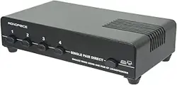
Front
This image represents the SSVC4. The SSVC6 has 6 zones.
The RF-SSVC4 and RF-SSVC6 are passive speaker selectors that allow
you to distribute an amplied stereo signal to multiple listening zones.
Guidelines
• When the connecting distance (length) is greater than 100 feet (30 m), 14-gauge cable should be used to reduce signal loss. For shorter distances,
16~18-gauge cables are acceptable.
• When connecting the speakers to an amplier, make note of the polarity (positive +/red to positive, negative -/black to negative). For best sound
performance, make sure that polarity is consistent among the amplier, volume control, speaker selector, and speakers.
• The impedance protection circuit of these selectors can be manually activated. The protection circuit switch should be on whenever three or more
zones are selected. When the protection switch is on, it can prevent the amplier from overloading.
• To realize the maximum performance of your amplier, turn the impedance protection switch o when one or two zones are selected.
Rear