
PN-L602B
LCD MONITOR
OPERATION MANUAL
IMPORTANT:
To aid reporting in case of loss or theft, please record the
product’s model and serial numbers in the space provided.
The numbers are located in the rear of the product.
Model No.:
Serial No.:
U.S.A. ONLY
FOR CUSTOMERS IN U.K.
IMPORTANT
The wires in this mains lead are coloured in accordance with the following code:
GREEN-AND-YELLOW: Earth
BLUE: Neutral
BROWN: Live
As the colours of the wires in the mains lead of this apparatus may not correspond with the coloured markings identifying the
terminals in your plug proceed as follows:
•ThewirewhichiscolouredGREEN-AND-YELLOWmustbeconnectedtotheterminalintheplugwhichismarkedbythe
letter E or by the safety earth
orcolouredgreenorgreen-and-yellow.
•ThewirewhichiscolouredBLUEmustbeconnectedtotheterminalwhichismarkedwiththeletterN or coloured black.
•ThewirewhichiscolouredBROWNmustbeconnectedtotheterminalwhichismarkedwiththeletterL or coloured red.
Ensurethatyourequipmentisconnectedcorrectly.Ifyouareinanydoubtconsultaqualiedelectrician.
“WARNING: THIS APPARATUS MUST BE EARTHED.”
3
E
IMPORTANT INFORMATION
WARNING: TOREDUCETHERISKOFFIREORELECTRICSHOCK,DONOTEXPOSETHISPRODUCT
TORAINORMOISTURE.
RISKOFELECTRIC
SHOCK
DONOTOPEN
CAUTION
CAUTION: TOREDUCETHERISKOFELECTRIC
SHOCK,DONOTREMOVECOVER.
NOUSER-SERVICEABLEPARTS
INSIDE.
REFERSERVICINGTOQUALIFIED
SERVICEPERSONNEL.
Thelightningashwitharrowheadsymbol,within
anequilateraltriangle,isintendedtoalertthe
user to the presence of uninsulated “dangerous
voltage” within the product’s enclosure that may
beofsufcientmagnitudetoconstituteariskof
electric shock to persons.
The exclamation point within a triangle is
intended to alert the user to the presence of
important operating and maintenance (servicing)
instructions in the literature accompanying the
product.
WARNING:
FCCRegulationsstatethatanyunauthorizedchangesormodicationstothisequipmentnotexpresslyapprovedbythe
manufacturercouldvoidtheuser’sauthoritytooperatethisequipment.
NOTE:
ThisequipmenthasbeentestedandfoundtocomplywiththelimitsforClassAdigitaldevice,pursuanttoPart15ofthe
FCCRules.Theselimitsaredesignedtoprovidereasonableprotectionagainstharmfulinterferencewhentheequipment
isoperatedinacommercialenvironment.Thisequipmentgenerates,uses,andcanradiateradiofrequencyenergyand,if
not installed and used in accordance with the instruction manual, may cause harmful interference to radio communications.
Operationofthisequipmentinaresidentialareaislikelytocauseharmfulinterferenceinwhichcasetheuserwillberequired
to correct the interference at his own expense.
ThisproductutilizesaCRcoinLithiumbatterywhichcontainsaPerchloratematerial.
Special handling for this material may apply,
Californiaresidents,Seewww.dtsc.ca.gov/hazardouswaste/perchlorate/
Others,consultlocalenvironmentalofcers.
U.S.A. ONLY
4
E
IMPORTANT INFORMATION (Continued)
A. Information on Disposal for Users (private households)
1. In the European Union
Attention:Ifyouwanttodisposeofthisequipment,pleasedonotusetheordinarydustbin!
Usedelectricalandelectronicequipmentmustbetreatedseparatelyandinaccordancewithlegislationthatrequiresproper
treatment,recoveryandrecyclingofusedelectricalandelectronicequipment.
Followingtheimplementationbymemberstates,privatehouseholdswithintheEUstatesmayreturntheirusedelectricaland
electronicequipmenttodesignatedcollectionfacilitiesfreeofcharge*.Insomecountries*yourlocalretailermayalsotake
back your old product free of charge if you purchase a similar new one.
*)Pleasecontactyourlocalauthorityforfurtherdetails.
Ifyourusedelectricalorelectronicequipmenthasbatteriesoraccumulators,pleasedisposeoftheseseparatelybeforehand
accordingtolocalrequirements.
Bydisposingofthisproductcorrectlyyouwillhelpensurethatthewasteundergoesthenecessarytreatment,recoveryand
recycling and thus prevent potential negative effects on the environment and human health which could otherwise arise due
to inappropriate waste handling.
2. In other Countries outside the EU
If you wish to discard this product, please contact your local authorities and ask for the correct method of disposal.
ForSwitzerland:Usedelectricalorelectronicequipmentcanbereturnedfreeofchargetothedealer,evenifyoudon’t
purchaseanewproduct.Furthercollectionfacilitiesarelistedonthehomepageofwww.swico.chorwww.sens.ch.
B. Information on Disposal for Business Users
1. In the European Union
If the product is used for business purposes and you want to discard it:
PleasecontactyourSHARPdealerwhowillinformyouaboutthetake-backoftheproduct.Youmightbechargedforthe
costsarisingfromtake-backandrecycling.Smallproducts(andsmallamounts)mightbetakenbackbyyourlocalcollection
facilities.
ForSpain:Pleasecontacttheestablishedcollectionsystemoryourlocalauthorityfortake-backofyourusedproducts.
2. In other Countries outside the EU
If you wish to discard of this product, please contact your local authorities and ask for the correct method of disposal.
Attention: Your product is marked with this symbol. It means that used electrical and electronic products
should not be mixed with general household waste. There is a separate collection system for these products.
The battery supplied with this product contains traces of Lead.
ForEU:
Thecrossed-outwheeledbinimpliesthatusedbatteriesshouldnotbeputtothegeneralhousehold
waste!Thereisaseparatecollectionsystemforusedbatteries,toallowpropertreatmentandrecyclingin
accordance with legislation. Please contact your local authority for details on the collection and recycling
schemes.
ForSwitzerland:
The used battery is to be returned to the selling point.
Forothernon-EUcountries:
Please contact your local authority for correct method of disposal of the used battery.
“BATTERYDISPOSAL”
THISPRODUCTCONTAINSALITHIUMPRIMARY(MANGANESSDIOXIDE)MEMORYBACK-UPBATTERYTHAT
MUSTBEDISPOSEDOFPROPERLY.PLEASECONTACTYOURLOCALSHARPDEALERORAUTHORIZEDSERVICE
REPRESENTATIVEFORASSISTANCEINDISPOSINGOFTHISBATTERY.
U.S.A.ANDCANADAONLY
EUONLY
EUONLY

5
E
ThankyouforyourpurchaseofaSHARPLCDproduct.Toensuresafetyandmanyyearsoftrouble-freeoperationofyour
product, please read the Safety Precautions carefully before using this product.
SAFETY PRECAUTIONS
Electricityisusedtoperformmanyusefulfunctions,butitcanalsocausepersonalinjuriesandpropertydamageifimproperly
handled.Thisproducthasbeenengineeredandmanufacturedwiththehighestpriorityonsafety.However,improperusecan
resultinelectricshockand/orre.Inordertopreventpotentialdanger,pleaseobservethefollowinginstructionswheninstalling,
operatingandcleaningtheproduct.ToensureyoursafetyandprolongtheservicelifeofyourLCDproduct,pleasereadthe
following precautions carefully before using the product.
1. Readinstructions—Alloperatinginstructionsmustbereadandunderstoodbeforetheproductisoperated.
2. Keepthismanualinasafeplace—Thesesafetyandoperatinginstructionsmustbekeptinasafeplaceforfuture
reference.
3. Observewarnings—Allwarningsontheproductandintheinstructionsmustbeobservedclosely.
4. Followinstructions—Alloperatinginstructionsmustbefollowed.
5. Cleaning—UnplugthepowercordfromtheACoutletbeforecleaningtheproduct.Useadryclothtocleantheproduct.Do
notuseliquidcleanersoraerosolcleaners.
6. Attachments—Donotuseattachmentsnotrecommendedbythemanufacturer.Useofinadequateattachmentscanresult
in accidents.
7. Waterandmoisture—Donotusetheproductnearwater.Donotinstalltheproductinaplacewherewatermaysplashonto
it.Becarefulofequipmentwhichdrainswatersuchasanair-conditioner.
8. Ventilation—Theventsandotheropeningsinthecabinetaredesignedforventilation.
Donotcoverorblocktheseventsandopeningssinceinsufcientventilationcancauseoverheatingand/orshortenthelife
oftheproduct.Donotplacetheproductonasofa,rugorothersimilarsurface,sincetheycanblockventilationopenings.
Donotplacetheproductinanenclosedplacesuchasabookcaseorrack,unlessproperventilationisprovidedorthe
manufacturer’s instructions are followed.
9. Powercordprotection—Thepowercordsmustberoutedproperlytopreventpeoplefromsteppingonthemorobjectsfrom
resting on them.
10. Thescreenusedinthisproductismadeofglass.Therefore,itcanbreakwhentheproductisdroppedorappliedwith
impact.Becarefulnottobeinjuredbybrokenglasspiecesincasethescreenbreaks.
11. Overloading—DonotoverloadACoutletsorextensioncords.Overloadingcancausereorelectricshock.
12. Enteringofobjectsandliquids—Neverinsertanobjectintotheproductthroughventsoropenings.Highvoltageowsin
theproduct,andinsertinganobjectcancauseelectricshockand/orshortinternalparts.
Forthesamereason,donotspillwaterorliquidontheproduct.
13. Servicing—Donotattempttoservicetheproductyourself.Removingcoverscanexposeyoutohighvoltageandother
dangerousconditions.Requestaqualiedservicepersontoperformservicing.
14. Repair—Ifanyofthefollowingconditionsoccurs,unplugthepowercordfromtheACoutlet,andrequestaqualiedservice
person to perform repairs.
a. Whenthepowercordorplugisdamaged.
b. Whenaliquidwasspilledontheproductorwhenobjectshavefallenintotheproduct.
c. Whentheproducthasbeenexposedtorainorwater.
d. Whentheproductdoesnotoperateproperlyasdescribedintheoperatinginstructions.
Donottouchthecontrolsotherthanthosedescribedintheoperatinginstructions.Improperadjustmentofcontrols
notdescribedintheinstructionscancausedamage,whichoftenrequiresextensiveadjustmentworkbyaqualied
technician.
e. Whentheproducthasbeendroppedordamaged.
f. Whentheproductdisplaysanabnormalcondition.Anynoticeableabnormalityintheproductindicatesthattheproduct
needs servicing.
15. Replacementparts—Incasetheproductneedsreplacementparts,makesurethattheservicepersonusesreplacement
partsspeciedbythemanufacturer,orthosewiththesamecharacteristicsandperformanceastheoriginalparts.Useof
unauthorizedpartscanresultinre,electricshockand/orotherdanger.
16. Safetychecks—Uponcompletionofserviceorrepairwork,requesttheservicetechniciantoperformsafetychecksto
ensure that the product is in proper operating condition.
17. Wallmounting—Whenmountingtheproductonawall,besuretoinstalltheproductaccordingtothemethod
recommended by the manufacturer.
18. Heatsources—Keeptheproductawayfromheatsourcessuchasradiators,heaters,stovesandotherheat-generating
products(includingampliers).
DEAR SHARP CUSTOMER
6
E
SAFETY PRECAUTIONS (Continued)
19. Batteries—Incorrectuseofbatteriesmaycausethebatteriestoburstorignite.Aleakybatterymaycorrodetheequipment,
dirty your hands or spoil your clothing. In order to avoid these problems, make sure to observe the precautions below:
•Usethespeciedbatteriesonly.
•Installthebatterieswithdueattentiontotheplus(+)andminus(-)sidesofthebatteriesaccordingtotheinstructionsinthe
compartment.
•Donotmixoldandnewbatteries.
•Donotmixbatteriesofdifferenttypes.Voltagespecicationsofbatteriesofthesameshapemayvary.
•Replaceanexhaustedbatterywithanewonepromptly.
•Ifyouwillnotusetheremotecontrolforalongtime,removethebatteries.
•Ifleakedbatteryuidgetsonyourskinorclothing,rinseimmediatelyandthoroughly.Ifitgetsintoyoureye,batheyour
eyewellratherthanrubbingandseekmedicaltreatmentimmediately.Leakedbatteryuidthatgetsintoyoureyeoryour
clothing may cause a skin irritation or damage your eye.
20. Usageofthemonitormustnotbeaccompaniedbyfatalrisksordangersthat,couldleaddirectlytodeath,personalinjury,
severe physical damage or other loss, including nuclear reaction control in nuclear facility, medical life support system, and
missile launch control in a weapon system.
21. Donotstayincontactwiththepartsoftheproductthatbecomehotforlongperiodsoftime.Doingsomayresultin
low-temperatureburns.
WARNING:
This is a class A product. In a domestic environment this product may cause radio interference in which case the user may be
requiredtotakeadequatecountermeasures.
TomaintaincompliancewithEMCregulations,useshieldedcablestoconnecttothefollowingterminals:PC/AVDVI-Doutput
terminal,PC/AVDVI-Dinputterminal,PC/AVHDMIinputterminal,PCD-SUBinputterminal,PCRGBinputterminals,and
RS-232Cinput/outputterminals.
Ifamonitorisnotpositionedinasufcientlystablelocation,itcanbepotentiallyhazardousduetofalling.Manyinjuries,
particularly to children, can be avoided by taking simple precautions such as:
•Usingxingdeviceslikewallmountbracketsrecommendedbythemanufacturer.
•Onlyusingfurniturethatcansafelysupportthemonitor.
•Ensuringthemonitorisnotoverhangingtheedgeofthesupportingfurniture.
•Notplacingthemonitorontallfurniture(forexample,cupboardsorbookcases)withoutanchoringboththefurnitureandthe
monitor to a suitable support.
•Notstandingthemonitorsonclothorothermaterialsplacedbetweenthemonitorandsupportingfurniture.
•Educatingchildrenaboutthedangersofclimbingonfurnituretoreachthemonitororitscontrols.
Especially for child safety
-Don’tallowchildrentoclimbonorplaywiththemonitor.
-Don’tplacethemonitoronfurniturethatcaneasilybeusedassteps,suchasachestofdrawers.
-Rememberthatchildrencanbecomeexcitedwhilewatchingaprogram,especiallyona“largerthanlife”monitor.Care
should be taken to place or install the monitor where it cannot be pushed, pulled over, or knocked down.
-Careshouldbetakentorouteallcordsandcablesconnectedtothemonitorsothattheycannotbepulledorgrabbedby
curious children.

7
E
-TheTFTcolorLCDpanelusedinthismonitorismadewith
theapplicationofhighprecisiontechnology.However,there
may be minute points on the screen where pixels never light
or are permanently lit. Also, if the screen is viewed from
an acute angle there may be uneven colors or brightness.
Please note that these are not malfunctions but common
phenomenaofLCDsandwillnotaffecttheperformanceof
the monitor.
-Donotdisplayastillpictureforalongperiod,asthiscould
cause a residual image.
-Neverrubortapthemonitorwithhardobjects.
-PleaseunderstandthatSHARPCORPORATIONbearsno
responsibility for errors made during use by the customer or
a third party, nor for any other malfunctions or damage to this
product arising during use, except where indemnity liability is
recognizedunderlaw.
-Thismonitoranditsaccessoriesmaybeupgradedwithout
advance notice.
-Donotusethemonitorwherethereisalotofdust,where
humidity is high, or where the monitor may come into contact
withoilorsteam,asthiscouldleadtore.
-Ensurethatthemonitordoesnotcomeintocontactwith
waterorotheruids.Ensurethatnoobjectssuchaspaper
clipsorpinsenterthemonitorasthiscouldleadtoreor
electric shock.
-Donotplacethemonitorontopofunstableobjectsorin
unsafeplaces.Donotallowthemonitortoreceivestrong
shocksortostronglyvibrate.Causingthemonitortofallor
topple over may damage it.
-Donotusethemonitornearheatingequipmentorinplaces
where there is likelihood of high temperature, as this may
leadtogenerationofexcessiveheatandoutbreakofre.
-Donotusethemonitorinplaceswhereitmaybeexposedto
direct sunlight.
-TheACoutletshallbeinstalledneartheequipmentandshall
be easily accessible.
-DonottouchthescreenwhilethePCisstartingup,since
it will be detected as a failure of the infrared transmitter/
receiverelementsandwillleadtoamalfunction.Whenthis
occurs,restartthePC.
-Donotoperatethescreenwithahardorpointedobjectsuch
asangernail,pen,orpencil.
-Twotouchpanelscannotbeusedwhentwodisplaysare
connected to the computer.
Only the touch panel on the display that is set as the primary
monitor will be operable.
-IfanotherUSBdeviceisconnectedtothecomputertowhich
thetouchpanelisconnected,donotoperatetheUSBdevice
during touch panel input. Input may not take place correctly.
-Iftwotouchpanelsareusedincloseproximitytoeachother,
use handwriting mode. The touch pens will interfere with
each other and will not operate correctly.
-Iftheinfraredtransmitter/receiverbecomesdirty,
malfunctioning may result. Use a soft cloth to gently wipe dirt
off the infrared transmitter/receiver.
-Ifdustaccumulatesinsidetheinfraredtransmitter/receiver,
the product cannot transmit or receive infrared rays properly,
resulting in a malfunction. To clean the dust accumulated
inside,contactanauthorizedSHARPservicingdealeror
servicecenter(extrachargerequired).
The Power Cord
-Useonlythepowercordsuppliedwiththemonitor.
-Donotdamagethepowercordnorplaceheavyobjectson
it, stretch it or over bend it. Also, do not add extension cords.
Damagetothecordmayresultinreorelectricshock.
-Donotusethepowercordwithapowertap.
Addinganextensioncordmayleadtoreasaresultof
overheating.
-Donotremoveorinsertthepowerplugwithwethands.
Doingsocouldresultinelectricshock.
-Unplugthepowercordifitisnotusedforalongtime.
-Donotattempttorepairthepowercordifitisbroken
or malfunctioning. Refer the servicing to the service
representative.
Manual Scope
-Microsoft,Windows,WindowsVistaandInternetExplorer
areregisteredtrademarksofMicrosoftCorporation.
-HDMI,theHDMILogoandHigh-DenitionMultimedia
InterfacearetrademarksorregisteredtrademarksofHDMI
LicensingLLC.
-Adobe,Acrobat,andReaderareeitherregisteredtrademarks
or trademarks of Adobe Systems Incorporated in the United
States and/or other countries.
-Intel,Celeron,andIntelCore2Duoaretrademarksor
registeredtrademarksofIntelCorporationoritssubsidiaries
in the U.S.A. and other countries.
-AMD,AMDSempron,AMDAthlon,andcombinationsthereof
aretrademarksofAdvancedMicroDevices,Inc.
-ThisproductcomeswithRICOHBitmapFontsproducedand
soldbyRICOHCOMPANY,LTD.
-Allotherbrandandproductnamesaretrademarksor
registered trademarks of their respective holders.
-LanguageofOSDmenuusedinthismanualisEnglishby
way of example.
-Illustrationsinthismanualmaynotexactlyrepresentthe
actual product or display.
LED Backlight
● TheLEDbacklightinthisproducthasalimitedlifetime.
*Ifthescreengetsdarkordoesnotturnon,itmaybe
necessarytoreplacetheLEDbacklight.ThisLED
backlight is exclusive to this product and must be replaced
byanauthorizedSHARP servicing dealer or service
center.
*PleasecontactyourlocalSHARP servicing dealer or
service center for assistance.
TIPS AND SAFETY INSTRUCTIONS
8
E
MOUNTING PRECAUTIONS
• Thisproductisforuseindoors.
• AmountingbracketcompliantwithVESAspecicationsis
required.
• Sincethemonitorisheavy,consultyourdealerbefore
installing,removingormovingthemonitor.
• Mountingthemonitoronthewallrequiresspecialexpertise
andtheworkmustbeperformedbyanauthorizedSHARP
dealer.Youshouldneverattempttoperformanyofthis
workyourself.Ourcompanywillbearnoresponsibility
foraccidentsorinjuriescausedbyimpropermountingor
mishandling.
• Thismonitorcannotbeusedinverticalorientation.
• Usethemonitorwiththesurfaceperpendiculartoalevel
surface.Ifnecessary,themonitormaybetiltedupto20
degreesupward.
• Whenmovingthemonitor,besuretoholditwitheither
handlesorthecornersonthebottomoftheunit.Donot
placeyourhandonthescreen.Thismaycauseproduct
damage,failure,orinjury.
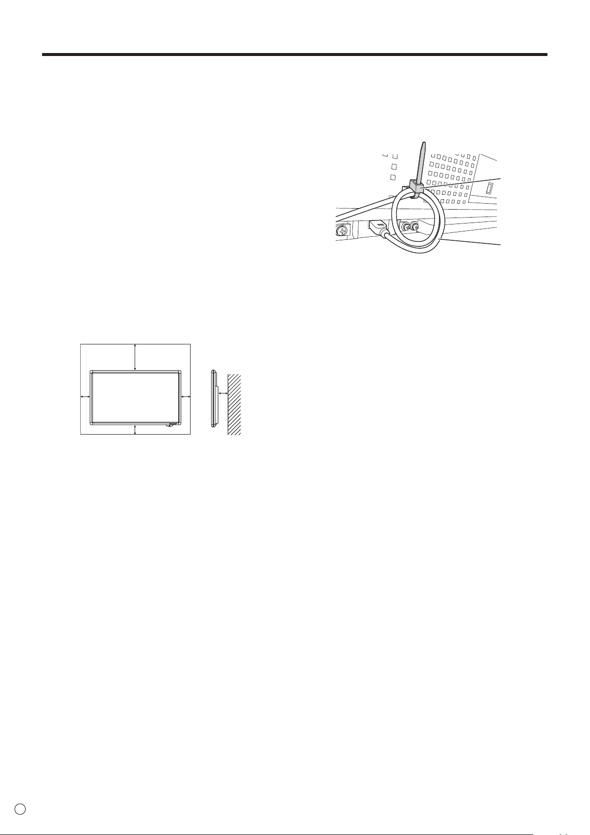
• Thismonitorshouldbeusedatanambienttemperature
between41°F(5°C)and95°F(35°C).Provideenough
spacearoundthemonitortopreventheatfrom
accumulatinginside.
7-7/8 [20]
Unit: inch [cm]
2 [5]
2
[5]
2
[5]
1-7/16 [3.5]
• Ifitisdifculttoprovidesufcientspaceforanyreason
suchastheinstallationofthemonitorinsideahousing,or
iftheambienttemperaturemaybeoutsideoftherange
of41°F(5°C)to95°F(35°C),installafanortakeother
measurestokeeptheambienttemperaturewithinthe
requiredrange.
• Temperatureconditionmaychangewhenusingthemonitor
togetherwiththeoptionalequipmentsrecommendedby
SHARP.Insuchcases,pleasecheckthetemperature
conditionspeciedbytheoptionalequipments.
• Donotblockanyventilationopenings.Ifthetemperature
insidethemonitorrises,thiscouldleadtoamalfunction.
• Donotplacethemonitoronadevicewhichgeneratesheat.
• Donotusetheproductinlocationswheretheunitis
exposedtodirectsunlightorotherstronglight.Sincethis
productoperateswithinfraredrays,suchlightmaycausea
malfunction.
• FixtheUSBcablewiththecableclamp(supplied).
(1) Coilthecableintotwoloopsapprox.1-9/16inches
(4cm)indiameteratapprox.5-7/8inches(15cm)
fromtheminiUSBconnector.
(2) FixtheloopstothexingpartabovetheUSBportwith
thecableclamp.
(2)
(1)

9
E
Forinformationonthetouchpaneldriver,seetheTouchPanelDriverOperationManual.ForinformationonthePenSoftware,
see the Pen Software Operation Manual.
Supplied Components
If any component should be missing, please contact your dealer.
LiquidCrystalDisplayMonitor:1
Remotecontrolunit:1
Cableclamp:3
Powercord:1
R-6battery(“AA”size):2
CD-ROM(UtilityDiskforWindows):1
SetupManual:1
Touchpen:1
* SharpCorporationholdsauthorshiprightstotheUtilityDiskprogram.Donotreproduceitwithoutpermission.
* Forenvironmentalprotection!
Donotdisposeofbatteriesinhouseholdwaste.Followthedisposalinstructionsforyourarea.
Pen tip (for touch pen): 2
Touch pen battery
(LR-03(“AAA”size)):1
USBcable:1
Eraser:1
Tray:1
Traymountingtting
(cover / bracket): x 2
System Requirements
To use the touch panel, the touch panel must be connected to a computer, and the touch panel driver and Pen Software must be
installedonthecomputerfromthesuppliedCD-ROM.Systemrequirementsforeachsoftwareprogramareasfollows.
Computer
PC/ATcompatiblecomputerwithaUSB1.1port(mustbeabletosupplya500mA(5.0V)current)
andabletooutputaresolutionof1920x1080.(CD-ROMdriverequiredforsoftwareinstallation.)
OS
WindowsXP(32-bitor64-bitversion),WindowsVista(32-bitor64-bitversion),Windows7(32-bit
or64-bitversion)
CPU
IntelCeleronorAMDSempron1.6GHzorfaster
IntelCore2DuoorAMDAthlonIIX22.8GHzorfasterrecommended
Memory Atleast2GB(atleast1GBforWindowsXP)
Freespaceonharddrive Atleast100MB(freespaceseparatelyrequiredfordatastorage)
Toconnectthetouchpanelandinstallthetouchpaneldriver,seetheTouchPanelDriverOperationManual.
To install the Pen Software, see the Pen Software Operation Manual.
Contents
IMPORTANT INFORMATION ............................................3
DEAR SHARP CUSTOMER ..............................................5
SAFETY PRECAUTIONS ..................................................5
TIPS AND SAFETY INSTRUCTIONS ...............................7
MOUNTING PRECAUTIONS ............................................8
Supplied Components .....................................................9
System Requirements .....................................................9
Part Names .....................................................................10
Connecting Peripheral Equipment ...............................12
ConnectionwithaPCorAVequipment .....................12
ConnectionwhenthePN-ZB01(optional)
is attached ..................................................................13
Connecting the Power Cord .........................................14
Binding Cables ...............................................................14
Removing the Handles ..................................................14
Preparing the Remote Control Unit ..............................15
Installing the batteries ................................................15
Remote control operation range .................................15
Turning Power On/Off ....................................................16
Turning on the main power.........................................16
Turning power on/off ..................................................16
Disablingpoweron/offoperations ..............................17
Touch Pen Preparations/Touch Action ........................18
Inserting the battery ...................................................18
Touch action and touch mode ....................................18
Touch action ...............................................................18
Other functions ...........................................................20
Cautionarypoints .......................................................20
Eraser .........................................................................20
Basic Operation .............................................................21
Menu Items .....................................................................23
Displayingthemenuscreen .......................................23
Menu item details .......................................................24
AdjustmentsforPCscreendisplay ............................30
Initialization (Reset)/Functional Restriction Setting
(FUNCTION) ....................................................................31
Controlling the Monitor with a PC (RS-232C) ..............32
PCconnection ............................................................32
Communicationconditions .........................................32
Communicationprocedure .........................................32
SettingoftheGAMMAuserdata ................................35
RS-232Ccommandtable ...........................................36
Controlling the Monitor with a PC (LAN) .....................43
Settings to connect to a LAN ......................................43
ControllingwithaPC ..................................................45
Troubleshooting .............................................................51
Specications ...............................................................53
Mounting Precautions
(For SHARP dealers and service engineers) ...............57
Traymountingscrews:M5x4/M4x2
Terminallabel:1
Used when installing the expansion board
PN-ZB01(optional).
CoverSharplogo:1
PlacethisstickerontotheSHARPlogoto
cover the logo.
10
E
n
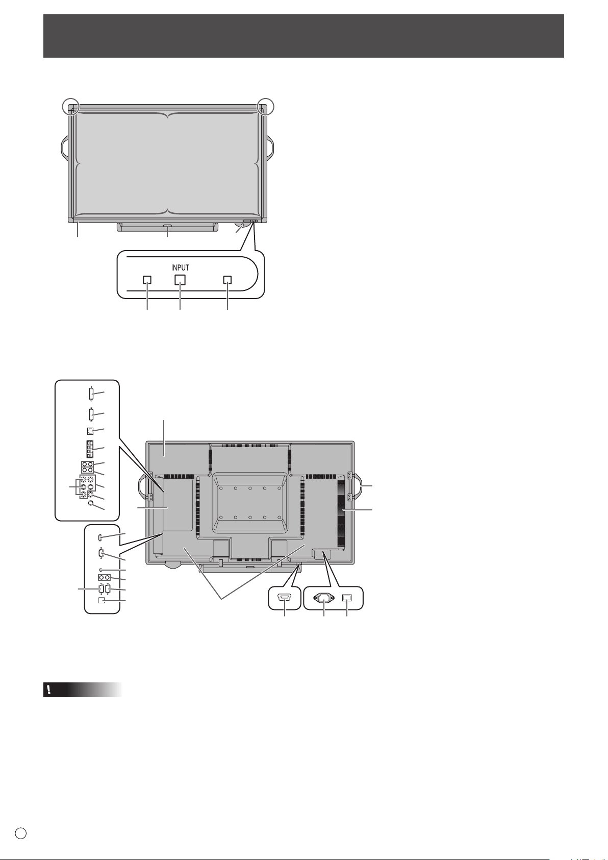
Front view
768
11
5
22
2
2
4
3
1. Touch pen ultrasonic sensor
2. Infrared transmitter/receiver
3. Power button (Seepage16.)
4. Tray
5. Touch panel power LED
6. Remote control sensor (Seepage15.)
7. Input switch (Seepage21.)
8. Power LED (Seepage16.)
Part Names
n
Rear view
18
17
16
19
22
21
20
24
23
2
1
4
1514
5
6
7
8
9
10
11
12
3
25
13
When the PN-ZB01
(optional) is attached
1. Optional attachment section
This section is used to connect optional
hardware for function expansion.
Offering this attachment location is
not a guarantee that future compatible
hardware attachments will be released.
2. Speakers
3. Handles (Seepage14.)
4. Vents
5. Expansion terminal cover
Additional input/output terminals are
availablebyattachingthePN-ZB01
expansion board (optional).
6. PC/AV HDMI input terminal (See page
12.)
7. PC D-sub input terminal (See page
12.)
8. Audio input terminal (Seepage12.)
9. Audio output terminals (Seepage12.)
10. RS-232C output terminal (See page
12.)
11. RS-232C input terminal (Seepage12.)
12. Optional terminal
This terminal is provided for possible
future (optional) function expansion.
Offering of this terminal is not a
guarantee that future expanded
functionality will be provided.
13. USB port
14. AC input terminal (Seepage14.)
15. Main power switch (Seepage16.)
Caution
• ConsultyourSHARPdealerforattachment/detachmentof
optional parts.
• Donotopentheexpansionterminalcoverbyyourself.
There are high voltage parts inside the cover which may
cause an electric shock.
When the PN-ZB01 (optional) is attached
16. PC/AV DVI-D input terminal (Seepage13.)
17. PC/AV DVI-D output terminal (Seepage13.)
18. LAN terminal (Seepage13.)
19. External speaker terminals (Seepage13.)
20. Audio 1 input terminals (Seepage13.)
21. Audio 2 input terminals (Seepage13.)
22. PC RGB input terminals (Seepage13.)
23. AV component input terminals (Seepage13.)
24. AV video input terminal (Seepage13.)
25. AV S-video input terminal (Seepage13.)
11
E
Part Names
n
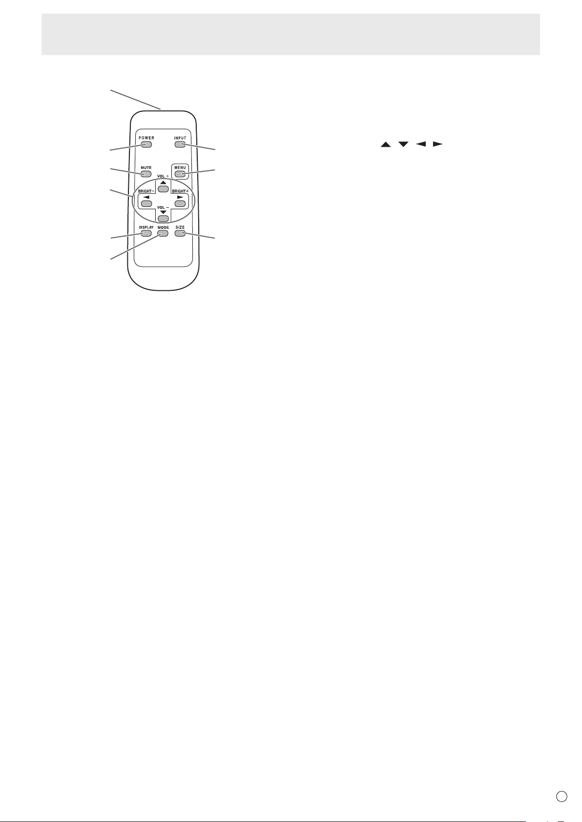
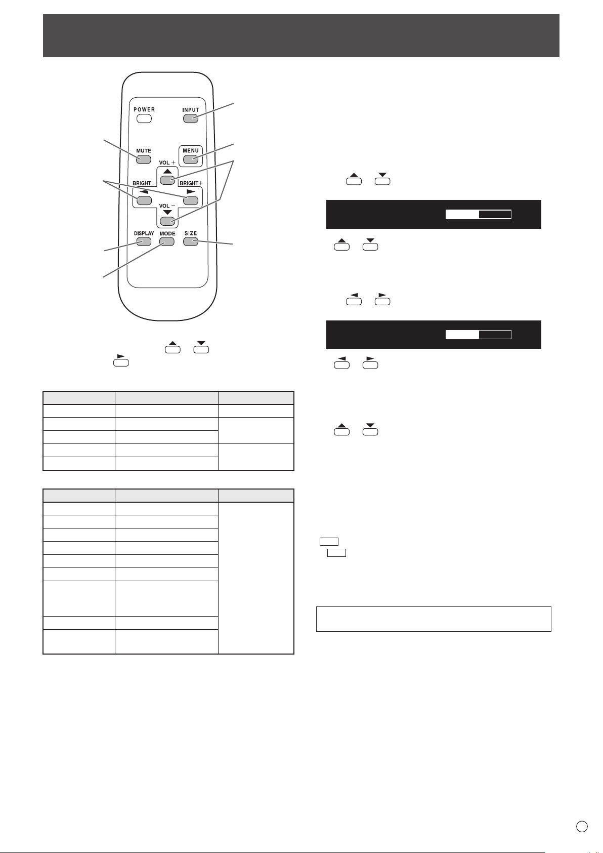
Remote control unit
1
2
3
4
5
6
9
8
7
1. Signal transmitter
2. POWER button(Seepage16.)
3. MUTE button(Seepage21.)
4. VOL +/- buttons(Seepage21.)
BRIGHT +/- buttons(Seepage21.)
Cursor control (
/ / / ) buttons
5. DISPLAY button(Seepage21.)
6. MODE button(Seepage21.)
7. INPUT button(Seepage21.)
8. MENU button(Seepage21.)
9. SIZE button(Seepage21.)
12
E
Connecting Peripheral Equipment
Caution
• Besuretoturnoffthemainpowerswitchanddisconnect
theplugfromthepoweroutletbeforeconnecting/
disconnectingcables.Also,readthemanualofthe
equipmenttobeconnected.
• Becarefulnottoconfusetheinputterminalwiththeoutput
terminalwhenconnectingcables.Accidentallyreversing
cablesconnectedtotheinputandoutputterminalsmay
causemalfunctionsandtheotherproblems.
TIPS
• Whenusingthetouchpanel,connecttheUSBcableto
thecomputer.Fordetails,seetheTouchPanelDriver
OperationManual.
• Imagesmaynotbedisplayedproperlydependingonthe
computer(videocard)tobeconnected.
• Ascreenwith1920x1080resolutionmaynotbedisplayed
correctlyonPCRGB.Inthiscase,checkthesettingsof
yourcomputer(videocard)toverifythatinputsignals
conformtospecicationsofthismonitor.(Seepage55.)
• IfthereisacheckboxtodisableEDIDindisplaycontrol
panel,checkitwhenusingPCRGB.
• UsetheautomaticscreenadjustmentwhenaPCscreen
isdisplayedforthersttimeusingPCD-SUBorPCRGB,
orwhenthesettingofthePCischanged.Thescreenis
adjustedautomaticallywhenSELFADJUSTintheOPTION
menuissettoON.
• Iftheaudiooutputfromtheplaybackdeviceisconnected
directlytospeakersorotherdevices,thevideoonthe
monitormayappeardelayedfromtheaudioportion.
Audioshouldbeplayedthroughthismonitorbyconnecting
theplaybackdevicetothemonitor’saudioinput,and
connectingthemonitor’saudiooutputtothespeakersor
otherdevices.
• Theaudioinputterminalsusedineachinputmodeare
factory-setasfollows.
Input mode
Audio input terminal
(Factory setting)
PCD-SUB,PCDVI-D,PCRGB
Audioinputterminal
AVDVI-D Audio1inputterminal
AVCOMPONENT(BNC),
AVS-VIDEO,AVVIDEO(BNC)
Audio2inputterminal
AVCOMPONENT(D-SUB),
AV
VIDEO
(D-SUB)
Audioinputterminal
PCHDMI,AVHDMI PC/AVHDMIinputterminal
Connection with a PC or AV equipment
1. PC/AV HDMI input terminal
• UseacommerciallyavailableHDMIcable(conformingto
theHDMIstandard).
• SetHDMIofINPUTSELECTontheOPTIONmenu
accordingtothedevicetobeconnected.
• SelecttheaudioinputterminaltobeusedinPCHDMI
orAVHDMIofAUDIOSELECTontheOPTIONmenu.
WhenHDMIisselected,connectiontotheaudioinput
terminalisunnecessary.
2. PC D-sub input terminal
• SetD-SUBofINPUTSELECTontheOPTIONmenu
accordingtothedevicetobeconnected.
• CommonterminalforAVCOMPONENTandAVVIDEO.
• WhenthePN-ZB01(optional)isattached,selecttheaudio
inputterminaltobeusedinPCD-SUBofAUDIOSELECT
ontheOPTIONmenu.
• TousewithAVVIDEO(D-SUB),connectthegreen
terminaltothedevice’svideooutput.
3. Audio input terminal
• Useanaudiocablewithoutresistance.
• WhenthePN-ZB01(optional)isattached,settheaudio
inputterminalusedforeachinputmodeinAUDIO
SELECTontheOPTIONmenu.
4. Audio output terminals
• Theoutputsoundvariesdependingontheinputmode.
• Thevolumeoftheoutputsoundcanbexedbysetting
AUDIOOUTPUT(RCA)ontheOPTIONmenu.
• Itisnotpossibletocontrolthesoundoutputfromthe
audiooutputterminalswiththeAUDIOmenu.
5. RS-232C input terminal
RS-232C output terminal
• YoucancontrolthemonitorfromaPCbyconnectinga
commerciallyavailableRS-232straightcablebetween
theseterminalsandthePC.
6. USB port
• Tousethetouchpanel,connectthetouchpaneltoyour
computerwiththeprovidedUSBcable.(TouchPanel
DriverOperationManual.)
13
15
7
14
8
12
10
9
1
2
3
4
5
5
When the PN-ZB01 (optional) is attached
11
6

13
E
Connecting Peripheral Equipment
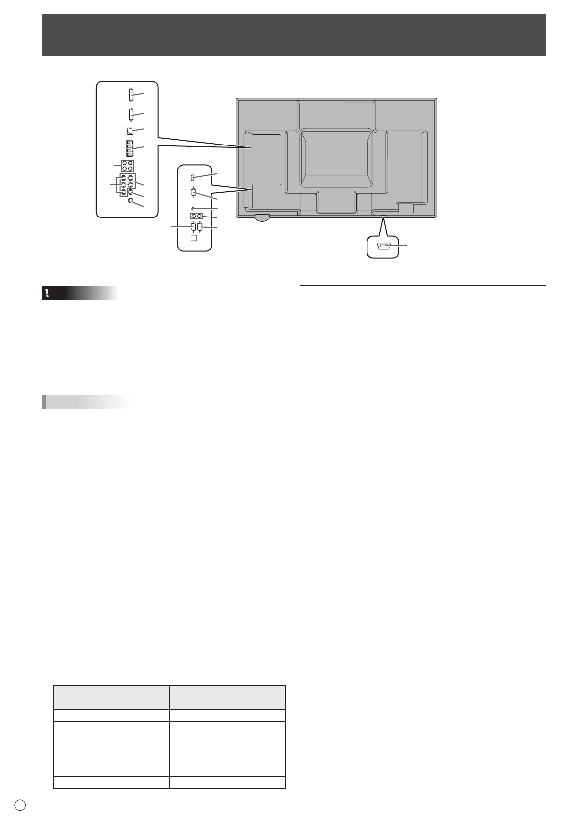
Connection when the PN-ZB01
(optional) is attached
ThePN-ZB01expansionboard(optional)allowstheuseof
additional connection terminals.
7. PC/AV DVI-D input terminal
• SetDVIofINPUTSELECTontheOPTIONmenu
according to the device to be connected.
• SelecttheaudioinputterminaltobeusedinPCDVI-Dor
AVDVI-DofAUDIOSELECTontheOPTIONmenu.
8. PC RGB input terminals
• SetBNCofINPUTSELECTontheOPTIONmenutoPC
RGBwhenusingthePCRGBinputterminals.
• SelecttheaudioinputterminaltobeusedinPCRGBof
AUDIOSELECTontheOPTIONmenu.
9. AV component input terminals
• SetBNCofINPUTSELECTontheOPTIONmenuto
AVCOMPONENTwhenusingtheAVcomponentinput
terminals.
• SelecttheaudioinputterminaltobeusedinAV
COMPONENTofAUDIOSELECTontheOPTIONmenu.
• CannotbeusedwhenD-SUBinINPUTSELECTonthe
OPTIONmenuissettoAVCOMPONENT.
10. AV video input terminal
• SelecttheaudioinputterminaltobeusedinAVVIDEOof
AUDIOSELECTontheOPTIONmenu.
• CannotbeusedwhenD-SUBinINPUTSELECTonthe
OPTIONmenuissettoAVVIDEO.
11. AV S-video input terminal
• SelecttheaudioinputterminaltobeusedinAVS-VIDEO
ofAUDIOSELECTontheOPTIONmenu.
12. Audio1 input terminals / Audio2 input terminals
• Settheaudioinputterminaltobeusedineachinput
modeinAUDIOSELECTontheOPTIONmenu.
13. LAN terminal
• YoucancontrolthemonitorfromaPConanetworkby
connecting a commercially available LAN cable between
this terminal and a network.
14. External speaker terminals
• Touseexternalspeakers,setSPEAKERSELECTonthe
SETUPmenutoEXTERNAL.
• Besuretouseexternalspeakerswithanimpedanceof6Ω
orgreaterandaratedinputofatleast7W.
132
Approx.
3-15/16 inch
(10 cm)
1.Attachaspeakercablecore(includedwiththePN-ZB01)to
the end of the speaker cable connected to the monitor.
2.Whilepushingthetab,insertthetipofthecable.
3. Release the tab.
TIPS
• Besuretoconnectthe+and-terminalsandtheleftand
right speakers properly.
• Avoidshortcircuitingthe+and-terminals.
• WhenSPEAKERSELECTissettoEXTERNAL,the
internal speakers are disabled.
15. PC/AV DVI-D output terminal
• ThevideoofthePC/AVDVI-Dinputcanbeoutputtoan
external device.
• OutputtingHDCP-encryptedvideorequiresanexternal
devicewhichsupportsHDCP.
• Thisterminalallowsthedaisychainconnectionofupto5
monitors.
TIPS
• Thelengthofthesignalcablesorsurroundingenvironment
mayaffecttheimagequality.
• Thescreenmaynotdisplayproperlywhenusingterminals
otherthanPCDVI-D/AVDVI-Dfortheinputmode.Inthis
case, turn off the power to all the monitors connected in a
daisy chain and then turn the power on again.
• WhenconnectingmonitorsinadaisychainsetAUTO
INPUTCHANGEtoOFF.
• Videooutputisdisabledinthefollowingcases:
Whenthepoweristurnedoff
Whenthemonitorisininputsignalwaitingmode
14
E
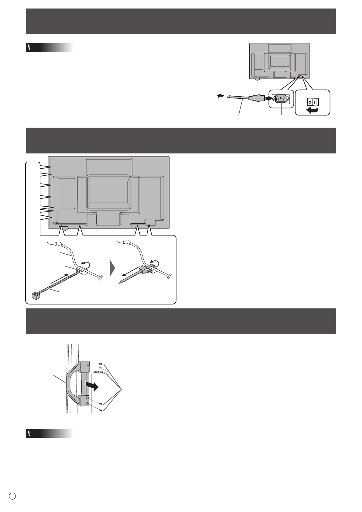
Connecting the Power Cord
Caution
• Useonlythepowercordsuppliedwiththemonitor.
1.Turnoffthemainpowerswitch.
2.Plugthepowercord(supplied)intotheACinputterminal.
3.Plugthepowercord(supplied)intotheACpoweroutlet.
Binding Cables
The cables connected to the terminals on the rear of the
monitor can be fastened with the cable clamp.
Insert the cable clamp into the cable clamp attachment on the
rear of the monitor and fasten the cables.
AC input terminal
1
Main power switch
Power cord (Supplied)
For power
outlet
2
3
Removing the Handles
Cable clamp
Cable clamp
attachment
Cable
The handles can be removed.
Handle
Handle screws
Caution
• Theremovablehandlesandhandlescrewsareforusewiththismonitor.Donotusethemforanyotherdevices.
• Toattachhandles,besuretousethehandlesandhandlescrewswhichwereremovedfromthemonitor.
• Besurethehandlesareattachedsecurely.
15
E
Preparing the Remote Control Unit
Installing the batteries
1. Pressthecovergentlyandslideitinthedirectionofthe
arrow.
2. See the instructions in the compartment and put in the
suppliedbatteries(R-6(“AA”size)x2)withtheirplus(+)
andminus(-)sidesorientedcorrectly.
3. Closethecover.
TIPS
• Whenthebatteriesbecomeexhausted,replacethemwith
new (commercially available) batteries.
• Thesuppliedbatteries(R-6(“AA”size)x2)maybecome
exhaustedquicklydependingonhowtheyarestored.
• Ifyouwillnotbeusingtheremotecontrolforalongtime,
remove the batteries.
• Usemanganeseoralkalinebatteriesonly.
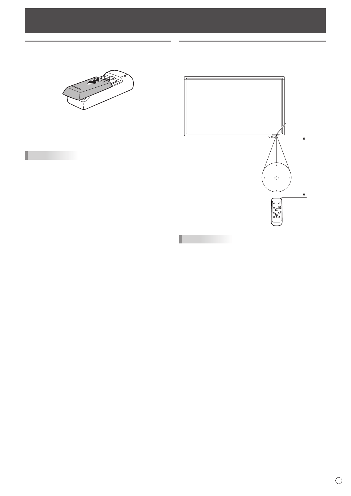
Remote control operation range
Theoperationrangeoftheremotecontrolunitisapprox.16.4
feet(5m)atanangleofapprox10°fromthecentertothetop/
bottom/right/left of the remote control sensor.
10°10°
10°
10°
Remote
control sensor
16.4
feet
(5 m)
TIPS
• Donotexposetheremotecontrolunittoshockbydropping
or stepping on it. This could lead to a malfunction.
• Donotexposetheremotecontrolunittoliquids,anddonot
place it in an area with high humidity.
• Theremotecontrolunitmaynotworkproperlyiftheremote
control sensor is under direct sunlight or strong lighting.
• Objectsbetweentheremotecontrolunitandtheremote
control sensor may prevent proper operation.
• Replacethebatterieswhentheyrunlowasthismay
shorten the remote control’s operation range.
• Ifauorescentlightisilluminatedneartheremotecontrol
unit, it may interfere with proper operation.
• Donotuseitwiththeremotecontrolofotherequipment
such as air conditioner, stereo components, etc.
16
E
Caution
• TurnonthemonitorrstbeforeturningonthePCor
playback device.
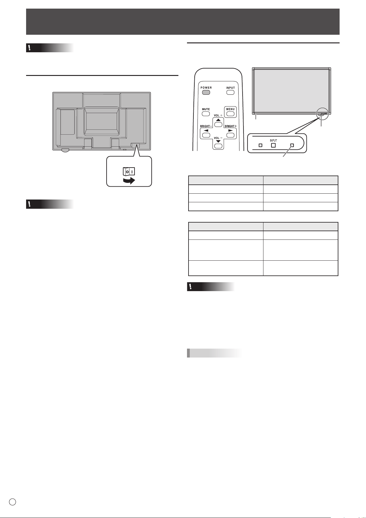
Turning on the main power
Main power switch
Caution
• Themainpowermustbeturnedon/offwiththemainpower
switch.Donotconnect/disconnectthepowercordorturn
the breaker on/off while the main power switch is on.
• WhenswitchingthemainpowerswitchorthePOWER
buttonoffandbackon,alwayswaitforatleast5seconds.
• Foracompleteelectricaldisconnection,pulloutthemain
plug.
Turning Power On/Off
Turning power on/off
PressthePOWERbuttontoturnthepowerON/OFF.
POWER
button
Power LED
Touch panel power LED
• StatusofthepowerLED
Status Status of the monitor
Greenlit Power on
Orange lit Power off (Standby mode)
Greenashing Input signal waiting mode
• StatusofthetouchpanelpowerLED
Status Status of the touch panel
Greenlit Operating normally
Blinkingorange
Alternately blinking green and
orange
Initializing
Off
Touch panel off (power not
supplied, etc.)
Caution
• WhenswitchingthemainpowerswitchorthePOWER
buttonoffandbackon,alwayswaitforatleast5seconds.
A short interval may result in a malfunction.
• WhenthetouchpanelpowerLEDblinksorangeor
alternately blinks green and orange, the touch panel is
beinginitialized.Donottouchthetouchpanelatthistime.
Touching the touch panel may cause malfunctioning.
TIPS
• Whenthemainpowerswitchisoff,themonitorcannotbe
turned on.
• Ifthemonitorisintheinputsignalstandbymodeandyou
pressthePOWERbuttonontheremotecontrolunit,the
monitor enters standby mode.
• SettingtheSCHEDULEashesthepowerLEDalternately
in red and orange in standby mode.
• Todisablethelogoscreenfromdisplayingwhenturning
thepowerON,setLOGOSCREENtoOFFontheSETUP
menu. (See page 26.)
17
E
Turning Power On/Off
n
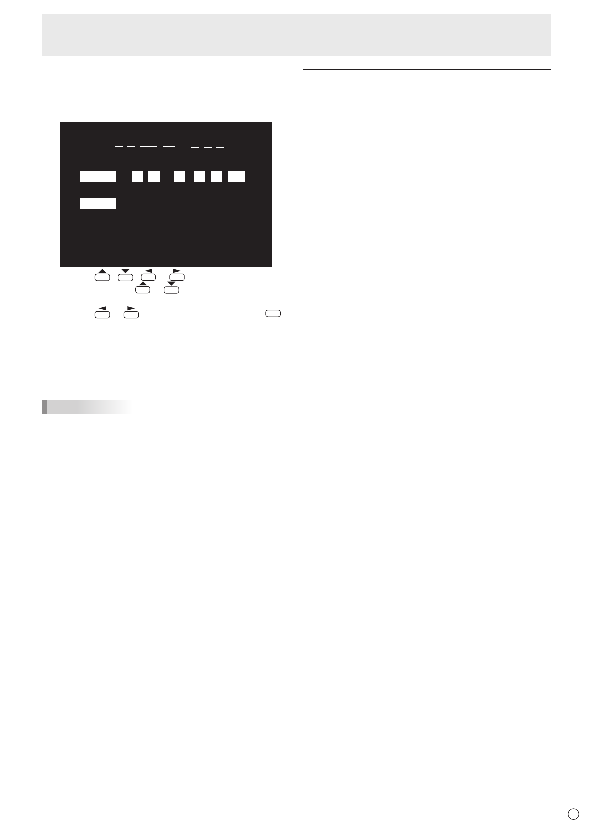
Date/time setting
• Ifthetimehasyettobesetwhenthemonitorisrstturned
on, the date/time setting screen appears. Set the date and
time.
DATE/TIME SETTING
SET
CANCEL
//
OK···[MENU]
: :
01 01 11
/
12 AM00
:/ 20
1. Press , , or to select the date and
time, and press
or to change the numerical
values.
2. Press
or toselectSETandthenpress
MENU
.
• Besuretosetthedateandtime.
• Thedate/timesettingscreenwillcloseautomaticallyifno
operationisperformedforabout15seconds.Thedate
andtimecanbesetusingDATE/TIMESETTINGfrom
the OPTION menu when the date/time setting screen
disappears.
TIPS
•
Setthedatein“Month/Day/Year”order.
•
Setthetimeona12-hourbasis.
•
The clock is maintained by the internal battery.
•
If you already set the time but the date/time setting
screen appears when the power is turned on, the
internal battery may be exhausted. Please contact
your local SHARP servicing dealer or service center for
assistance with battery replacement.
•
Estimatedservicelifeoftheinternalbattery:About5
years (depending on monitor operation)
•
The initial battery was inserted at the factory when the
monitor was shipped, so it may run out of power before
its expected operation life.
Disabling power on/off operations
Power on/power off operations can be disabled in order to
protect the monitor from an accidental power off. Set the
ADJUSTMENTLOCKinFUNCTIONmenuto“ON2”.(See
page31.)
18
E
Touch Pen Preparations/Touch Action
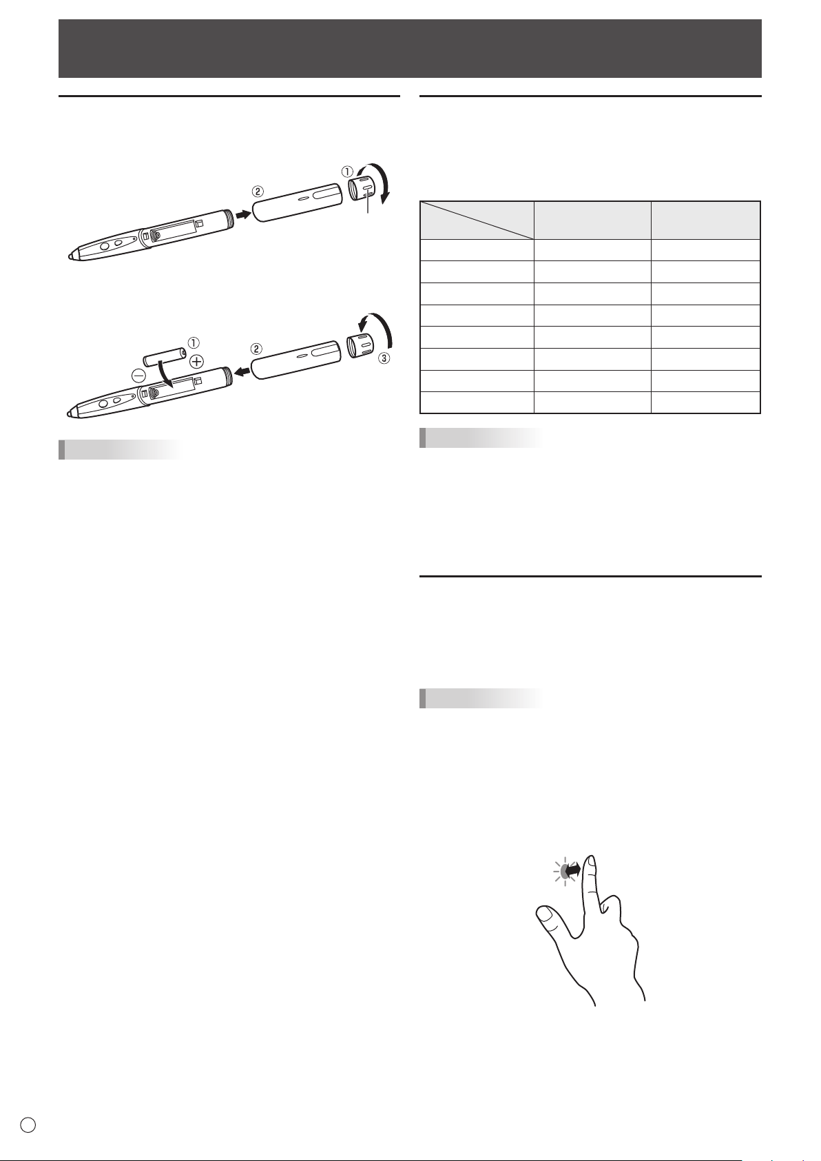
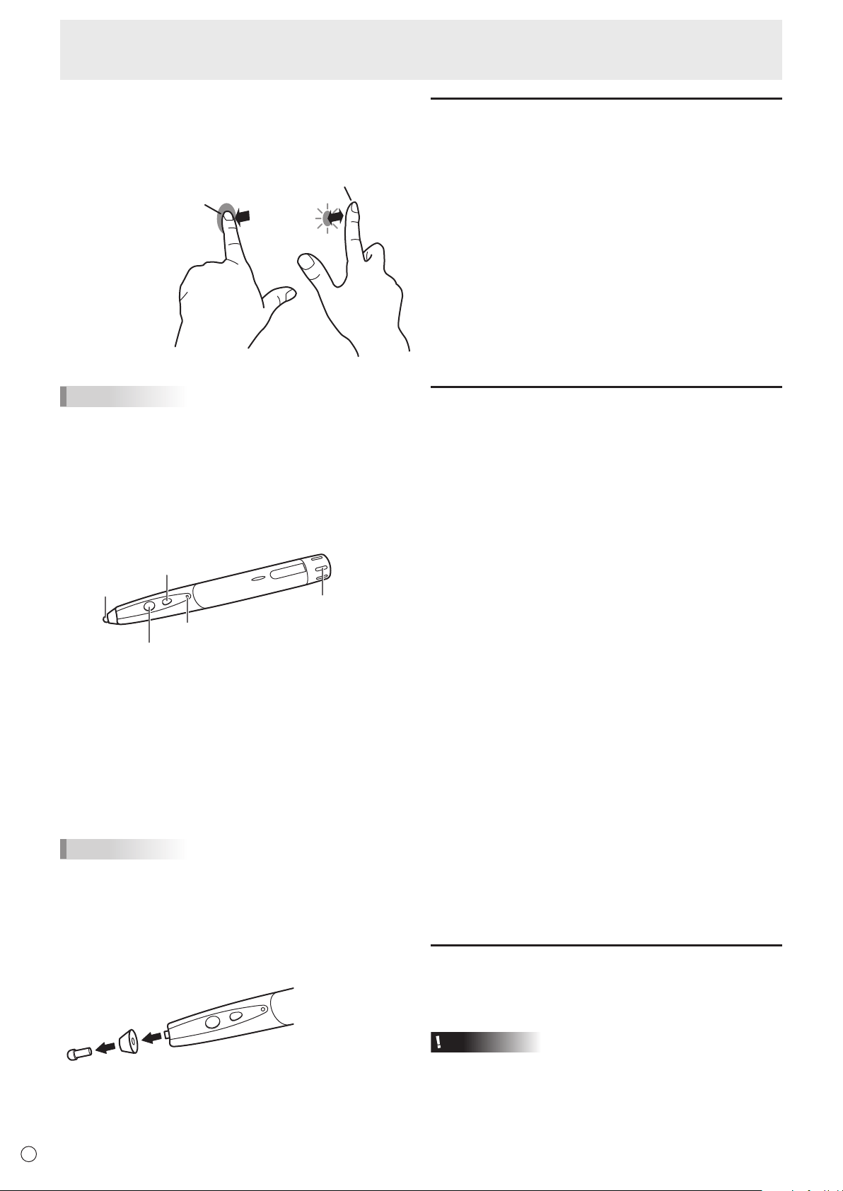
Inserting the battery
1. Rotatethebatterycapandremoveit,andthenpulloutthe
cover.
Battery cap
2. Insertthesuppliedbattery(LR-03(“AAA”size))inthe
orientation shown, and attach the cover and battery cap.
TIPS
• Thesuppliedbattery(LR-03(“AAA”size))maybe
exhausted in a short time, depending on how it was stored.
• Ifthetouchpenwillnotbeusedforanextendedtime,
remove the battery from the touch pen.
• Forthebattery,useanalkalinebattery.
Touch action and touch mode
Touch panel actions that can be used vary depending on the
touch mode setting in the touch panel driver.
InWindowsXP/WindowsVista,dualtouchmodecannotbe
used.
Touch mode
Touch action
Single touch mode
Dual touch mode
Single-tap Yes Yes
Double-tap Yes Yes
Drag-and-drop Yes Yes
Flicks No Yes
Press-and-hold No Yes
Pan No Yes
Zoom No Yes
Press-and-tap No Yes
TIPS
• Settingsfortouchpaneloperationsuchasthetouchmode
and actions of the function buttons can be changed in the
touchpaneldriver.Fordetails,seethemanualforthetouch
panel driver.
• InWindows7,ifthecheckmarkhasbeenremovedfrom
“Enablemulti-touchgesturesandinking”in“Penandtouch”
inControlPanel,selectthecheckbox.
Touch action
Whenthetouchpanelistouchedwiththepen,theinputmode
changestopenmode.Whentouchedwithyournger,the
input mode changes to handwriting mode. The input mode is
set by default to change automatically (Standard mode).
TIPS
• FortheproceduresforusingthetouchpeninthePen
Software, see the Pen Software Operation Manual.
n
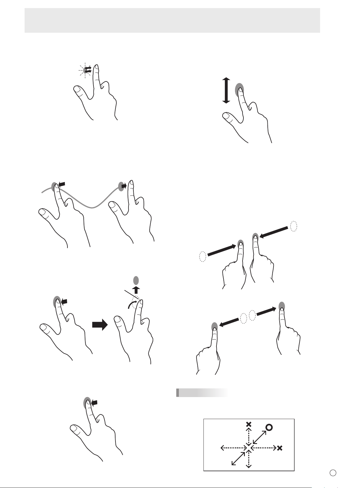
Common nger and pen actions
Single-tap
Same action as left-clickingamouse.
Touchwithyournger/pen.
19
E
Double-tap*
1
Sameactionasdouble-clickingamouse.
Quicklytouchtwicewithyournger/pen.
Whendouble-tappingwithyournger,besuretoliftyour
ngersufcientlyoffthescreenafterthersttap.Ifthere
isinsufcientdistancebetweenthescreenandyournger,
double-tapwillnottakeplace.
Drag-and-drop
Sameactionasdrag-and-dropwithamouse.
Touchthescreenwithyournger/penandmovewithoutlifting.
When you havenishedthemovement,liftyournger/pen.
Flicks*
2
Flickyournger/peninthedirectionofthefunctionyouwant
to use.
Flickyournger
Press-and-hold*
2
Sameactionasright-clickingamouse.
Pressbrieywithyournger/pen,andthenliftyournger/pen
from the screen.
Pan*
2
Use in a screen with a scrollbar.
Withyournger/pentouchingthescreen,moveinthe
direction you want to scroll. The screen scrolls in the direction
of the movement.
*
1 InWindowsXP/WindowsVista,thesettingscanbechangedin
the touch panel driver.
*
2 Thesettingscanbechangedin"Penandtouch"ofControlPanel
inWindows7.Fordetails,seeWindowsHelp.
n
Finger actions
Zoom
Use in a screen that is capable of enlargement/reduction.
Touchthescreenwithtwongersandmoveyourngers
closer together to reduce the view, or apart to enlarge the
view.
Reduction
Enlargement
TIPS
• Moveyourngerdiagonallyacrossthescreen.Ifyoumove
yourngerhorizontallyorvertically,thescreenmaynot
respond correctly.
Touch Pen Preparations/Touch Action
20
E
Press-and-tap
Sameactionasright-clickingamouse.
Withonengertouchingthescreen,taponce(singletap)with
anothernger.
Withonengertouching
Taponce(singletap)withanothernger
TIPS
• Thescreenmaynotrespondcorrectlyinthefollowing
cases:
Touchingistooquick
The distance between the two points is too short
The two points intersect
• Operationwiththetouchpenisnotpossible.
n
Pen actions
Pen tip
Function Button 2
Function Button 1
Ultrasonic transmitter
Battery indicator
Function Button 1
PressingFunctionButton1hasthesameactionasright-
clicking a mouse.
The battery indicator illuminates.
Function Button 2
InthePenSoftware,pressingFunctionButton2hasthe
action that is set in the Pen Software.
The battery indicator illuminates.
TIPS
• UseFunctionButton1andFunctionButton2nearthefront
of the screen. If too far away, operation will not be possible.
• PressFunctionButton1andFunctionButton2slowly
andrmly.Ifpressedtooquickly,theactionwillnotbe
recognized.
• Ifthepentipbecomeswornordamaged,replaceit.Pull
out the old pen tip and insert a new pen tip.
Other functions
InWindows7,touchpointerandinputpanelfunctionscanbe
used.
Forinformationonthesefunctions,seeWindowsHelp.
Touch pointer :
A translucent image of a mouse appears near the point
touched. The left/right buttons of the image can be clicked
to perform the same actions as left/right clicking a mouse.
Input panel :
A software keyboard and an input panel with handwriting
recognition appear on the screen.
InWindows7(excludingStarter),theinkfunctionofMicrosoft
Ofcecanbeused.
Handwrittencommentscanbewritten,andhandwritingcan
berecognized.
Fordetails, see MicrosoftOfceHelp.
Cautionary points
• Donotusethetouchpenforanypurposeotherthantouch
panel operation.
• Donotpresshardonthepentip.
•
Do not cover the ultrasonic transmitter of the touch pen with
yourhandornger.
• Operation will not take place correctly if there is an obstacle
between the infrared transmitter/receiver and the touch pen
oryournger.Operationwillnottakeplacecorrectlyifyour
ngers or your sleeve is near the screen.
• Ifthetouchpenisheldtooatagainstthescreen,the
touch position may not be correctly detected.
• Ifthetouchpendoesnotworkattheedgeofthescreen,
move it slowly.
• Donotstorewiththepentipofthetouchpenorfunction
button pressed. The battery will be exhausted.
• Donotusenearadevicethatemitsultrasonicwaves.The
touch pen uses ultrasonic waves and may not operate
correctly.
• Iftwotouchpanelsareusedincloseproximitytoeach
other, use handwriting mode. The touch pens will interfere
with each other and will not operate correctly.
• Ifthereisdirtorforeignmatteronthetipofthetouchpen,
removeit.Foreignmattermaydamagethescreen.
• Applicationssuchasascreensaverormediaplayermay
cause the resolution to automatically change. If "Resolution
ChangeNotice"isenabledinthetouchpaneldriver,a
resolution change message will appear. In this case,
disable"ResolutionChangeNotice",orchangethesetting
in the application so that it does not change the resolution.
• Thepenmaybeoutofpositionintheloginscreen.Inthis
case, use the keyboard or mouse.
• IftheUSBcablebecomesdisconnected,thetouchpanel
may not operate correctly after the cable is reconnected. In
this case, restart your computer.
Eraser
TheeraserisusedwiththePenSoftware.Fortheprocedure
for using the eraser, refer to the Pen Software Operation
Manual.
Caution
• Whenusingtheeraser,gentlybringtheclothsideinto
contact with the screen. Touching the screen with one of
thenon-clothsideswilldamagethescreen.
• Ifthereisanydirtorforeignmatteronthesurfacethat
contactsthescreen,removeit.Foreignmattermaydamage
the screen.
Touch Pen Preparations/Touch Action
21
E
Basic Operation
1
2
3
4
5
6
7
8
1. INPUT (Input mode selection)
The menu is displayed. Press
or to select the input
mode, and press
to enter.
* Youcanselecttheinputterminalbypressingtheinput
switch of the monitor.
Input mode Video Audio
PCD-SUB PCD-subinputterminal
*1
Audio input terminal
PCHDMI
PC/AVHDMIinputterminal
*2
*3
AVHDMI
PC/AVHDMIinputterminal
*2
AVCOMPONENT PCD-subinputterminal
*1
Audio input terminal
AVVIDEO PCD-subinputterminal
*1
When the PN-ZB01 (optional) is attached
Input mode Video Audio
PCDVI-D
PC/AVDVI-Dinputterminal
*4
*3
PCHDMI
PC/AVHDMIinputterminal
*2
PCD-SUB PCD-subinputterminal
*1
PCRGB PCRGBinputterminals
*5
AVDVI-D
PC/AVDVI-Dinputterminal
*4
AVHDMI
PC/AVHDMIinputterminal
*2
AVCOMPONENT
AVCOMPONENTinput
terminals
*5
PCD-subinputterminal
*1
AVS-VIDEO AVS-videoinputterminal
AVVIDEO
AVvideoinputterminal
PCD-subinputterminal
*1
*1 SelecttheterminaltobeusedinD-SUBofINPUT
SELECT.(Seepage26.)
*2 SelecttheterminaltobeusedinHDMIofINPUTSELECT.
(See page 26.)
*3 SelecttheterminalforAUDIOSELECTwhichisusedfor
audio input. (See page 26.)
*4 SelecttheterminaltobeusedinDVIofINPUTSELECT.
(See page 26.)
*5 SelecttheterminaltobeusedinBNCofINPUTSELECT.
(See page 26.)
2. MUTE
Turns off the volume temporarily.
PresstheMUTEbuttonagaintoturnthesoundbacktothe
previous level.
3. MENU
Displaysandturnsoffthemenuscreen.(seepage23.)
4. VOL +/- (Volume adjustment)
Pressing
or displaystheVOLUMEmenuwhenthe
menu screen is not displayed.
V OLUME 15
Press or toadjustthevolumeofthesound.
* Ifyoudonotpressanybuttonsforabout4seconds,the
VOLUMEmenuautomaticallydisappears.
5. BRIGHT +/- (Backlight adjustment)
Pressing
or displaystheBRIGHTmenuwhenthe
menu screen is not displayed.
BRIGHT 15
Press
or toadjustthebrightness.
* Ifyoudonotpressanybuttonsforabout4seconds,the
BRIGHTmenuautomaticallydisappears.
6. SIZE (Screen size selection)
The menu is displayed.
Press
or toselectthescreensize.(Seepage22.)
7. DISPLAY
Displaysmonitorinformation.Whenyoupressthisbutton
again, the display disappears.
WhenthePN-ZB01(optional)isattached,thedisplaychanges
fromINFORMATION1→INFORMATION2→cleardisplay,
and so on every time you press this button.
• Thedisplaydisappearsautomaticallyafterabout15
seconds.
•
LAN
is displayed during LAN communication.
• If
LAN
is displayed in red, there is a duplicate IP address.
8. MODE (Color mode selection)
Eachtimeyoupressthisbutton,thecolormodechangesin
the following order:
STD(Standard)→VIVID→sRGB→STD...
• sRGBappliestoPCinputonly.
sRGBisinternationalstandardofcolorrepresentation
speciedbyIEC(InternationalElectrotechnical
Commission).Colorconversionismadeintakingaccount
ofliquidcrystal’scharacteristicsandrepresentscolortone
close to its original image.
22
E
Basic Operation
n
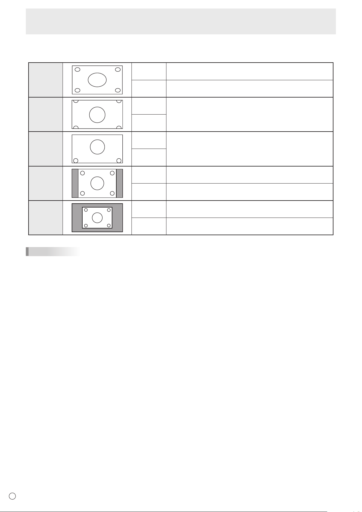
Switching the screen size
Evenwhenthescreensizeischanged,thedisplaymayremainthesamedependingontheinputsignal.
WIDE PCinput Displaysimagesoitllstheentirescreen.
AVinput Animagewitha4:3aspectratioisstretchedtolltheentire
screen.
ZOOM 1
PCinput Animagewitha4:3aspectratioisenlargedtolltheentirescreen
without changing the aspect ratio. The edges of the image may be
cut off.
AVinput
ZOOM 2
PCinput UsethissizeifZOOM1cutsoffthesubtitles.
AVinput
NORMAL
PCinput Displaysimagesoitllsthescreenwithoutchangingtheaspect
ratio of the input signals.
AVinput Displaystheentireimageoftheaspectratioof4:3without
changing the aspect ratio.
Dot by Dot
PCinput DisplaysthedotsofthesignalsinputfromtheconnectedPCas
the corresponding dots on the screen.
AVinput Displaysthedotsoftheinputsignalsasthecorrespondingdotson
the screen.
TIPS
• Usingthismonitor’sscreen-sizeswitchingordual-screendisplayfunctionstocompressorexpandthescreenforcommercial
orpublicviewinginestablishmentslikecafesorhotelsmayinfringeontherightsofthecreators,asprotectedbyCopyright
Law, so please be careful.
• Whendual-screendisplayisselected,thescreensizecannotbechanged.
• Theappearanceoftheoriginalvideomaychangeifyouselectascreensizewithadifferentaspectratiothantheoriginal
image(e.g.TVbroadcastorvideoinputfromexternalequipment).
• Whenanordinarynon-wideimage(4:3)isviewedwiththewholescreenusingthescreen-sizeswitchingfunctionofthis
monitor, the edge of the image may be lost or appear distorted. If you wish to respect the creator’s intentions, set the screen
sizeto“NORMAL”.
• Whenplayingcommercialsoftware,partsoftheimage(likesubtitles)maybecropped.Inthiscaseselecttheoptimalscreen
sizeusingthescreen-sizeswitchingfunctionofthismonitor.Withsomesoftware,theremaybenoiseordistortionatthe
edges of the screen. This is due to the characteristics of the software, and is not a malfunction.
• Dependingontheoriginalimagesize,blackbandsmayremainattheedgesofthescreen.
23
E
Menu Items
Displaying the menu screen
Video and audio adjustment and settings of various functions
are enabled. This section describes how to use the menu
items. See pages 24 to 27 for details of each menu items.
Caution
• Donotturnthemainpowerswitchoffwhilethemenuitems
arebeingdisplayed.Doingsomayinitializethesettings.
n
Example of operation
(Adjusting CONTRAST in the PICTURE menu)
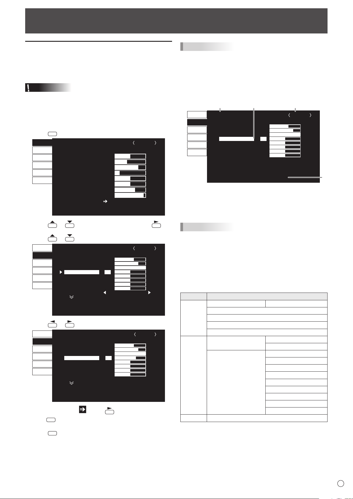
1. Press
MENU
to display the menu screen.
1 920x1080
V: 60 Hz H: 67.5 kHz
AUTO
CLOCK
PHASE
H-POS
V-POS
H-SIZE
V-SIZE
H-RESOLUTION
V-RESOLUTION
RESET
SCREEN
PICTURE
AUDIO
SETUP
OPTION
PIP/PbyP
600
25
610
37
50
50
1920
1080
SCREEN
1/1
END···[MENU]
PC D-SUB
2. Press
or
to select PICTURE, and press
.
3. Press
or
to select CONTRAST.
AUTO
ANALOG GAIN
ANALOG OFFSET
BRIGHT
CONTRAST
BLACK LEVEL
TINT
COLORS
SHARPNESS
RGB INPUT RANGE
64
86
31
30
30
30
30
12
1/2
FULL
PC D-SUB
PICTURE
SCREEN
PICTURE
AUDIO
SETUP
OPTION
PIP/PbyP
OK···[MENU]MOVE OSD···[DISPLAY]
1 920x1080
V: 60 Hz H: 67.5 kHz
4. Press or
to adjust the setting.
▲
▲
▲
AUTO
ANALOG GAIN
ANALOG OFFSET
BRIGHT
CONTRAST
BLACK LEVEL
TINT
COLORS
SHARPNESS
RGB INPUT RANGE
64
86
31
40
30
30
30
12
1/2
FULL
PC D-SUB
PICTURE
SCREEN
PICTURE
AUDIO
SETUP
OPTION
PIP/PbyP
OK···[MENU]MOVE OSD···[DISPLAY]
1 920x1080
V: 60 Hz H: 67.5 kHz
For items that have , press , make settings and then
press
MENU
.
5. Press
MENU
twice to close the menu screen.
TIPS
• Themenuwilldifferdependingontheinputmode.
• Themenuscreenwillcloseautomaticallyifnooperationis
performedforabout15seconds.(DATE/TIMESETTING,
SCHEDULEandLANSETUPscreenswillcloseinabout4
minutes.)
n
Menu screen display
▲
▲
▲
AUTO
ANALOG GAIN
ANALOG OFFSET
BRIGHT
CONTRAST
BLACK LEVEL
TINT
COLORS
SHARPNESS
RGB INPUT RANGE
64
86
31
30
30
30
30
12
1/2
FULL
PC D-SUB
SCREEN
PICTURE
AUDIO
SETUP
OPTION
PIP/PbyP
PICTURE
OK···[MENU]MOVE OSD···[DISPLAY]
1920x1080
V: 60 Hz H: 67.5 kHz
1
23
4
1 Name of the menu
2 Input mode
3 An item being selected (highlighted)
4 Screen resolution of input signal, and other data.
TIPS
• Itemsthatcannotbeselectedappearingray.
(e.g. Function not supported by the current input signal)
n
Menu Items
The displayed menu items vary depending on whether or not
the PN-ZB01 (optional) is attached.
The following menus will be displayed only when the PN-ZB01
(optional) is attached.
Menu Item
SETUP HOTPLUGCONTROL DVI
RS-232C/LANSELECT
LANSETUP
AUTOASSIGNFIXEDIPADDR.
SPEAKERSELECT
OPTION INPUTSELECT DVI
BNC
AUDIOSELECT PCDVI-D
PCD-SUB
PCRGB
AVDVI-D
AVCOMPONENT(BNC)
AVCOMPONENT(D-SUB)
AVS-VIDEO
AVVIDEO(BNC)
AVVIDEO(D-SUB)
PIP/PbyP PIP SOURCE
24
E
Menu item details
The menu will differ depending on the input mode.
n
SCREEN
You can move the menu screen display position each time
DISPLAY
is pressed.
AUTO (PC D-SUB/PC RGB)
TheCLOCK,PHASE,H-POS,andV-POSareautomatically
adjusted.
Pressing
performsadjustment.
UsethisautomaticadjustmentwhenyouusethePCD-sub
inputterminalorPCRGBinputterminalstodisplayaPC
screenforthersttimeorwhenyouchangethesettingof
thePC.(Seepage30.)
CLOCK (PC D-SUB/PC RGB)
Adjustsfrequencyfor sampling clock for applicable video.
Adjustwhenthereisickeringintheformofverticalstripes.
Whenusingtheadjustmentpattern(seepage30),make
adjustmentssothatno vertical stripe noise appears in it.
PHASE (PC D-SUB/PC RGB)
Adjustssamplingclockphaseforapplicablevideo.
Useful when small characters appear with low contrast and/
orthereareickersatcorners.
Whenusingtheadjustmentpattern(seepage30),make
adjustmentssothatnohorizontalstripenoiseappearsinit.
* AdjustmentstoPHASEshouldbemadeonlyafterCLOCK
has been correctly set.
H-POS
Adjustthehorizontalpositionoftheimage.
V-POS
Adjusttheverticalpositionoftheimage.
H-SIZE
Adjustthehorizontalsizeoftheimage.
V-SIZE
Adjusttheverticalsizeoftheimage.
H-RESOLUTION (PC D-SUB/PC RGB)
Sets properhorizontalresolutionwhentheresolutionof
inputsignalsisnotrecognizedproperly.(Adjustmentmaybe
impossible with some signals.)
V-RESOLUTION (PC D-SUB/PC RGB)
Sets proper vertical resolution when the resolution of input
signalsisnotrecognizedproperly.(Adjustmentmaybe
impossible with some signals.)
RESET
ResetsthevaluesoftheSCREENmenuitemstothefactory
preset values.
Select “ON” and then press
MENU
.
n
PICTURE
You can move the menu screen display position each time
DISPLAY
is pressed.
AUTO (PC D-SUB/PC RGB)
The ANALOGGAINandANALOGOFFSETare
automaticallyadjusted.
Pressing
performsadjustment.
ANALOG GAIN (PC D-SUB/PC RGB)
Adjuststhebrightportionsofthevideoinputsignal.
ANALOG OFFSET (PC D-SUB/PC RGB)
Adjuststhedarkportionsofthevideoinputsignal.
BRIGHT
Adjuststhebacklightbrightness.(InPIPmode,themainside
settingisreectedintheimage.)
CONTRAST
Adjuststhedifferencebetweenthebrightanddarkportions
of the image.
BLACK LEVEL
Adjuststheentirebrightnessofthevideosignals.
TINT
Adjuststhehue.Selecting+changesthecolortowards
green,andselecting-changesittowardsmagenta.
COLORS
Adjuststhecolorintensity.
SHARPNESS
Adjuststhesharpnessoftheimage.
RGB INPUT RANGE (PC DVI-D/PC HDMI/PC D-SUB/PC
RGB/AV DVI-D/AV HDMI)
SetstheRGBinputsignalrange.WhenusingHDMIsetto
AUTO,theRGBinputsignalisdetectedautomatically.Use
AUTO normally.
IftheRGBinputsignalrangecannotbesetappropriately
evenwhenusingAUTO,setaccordingtotheimage.When
the setting is different, images will be displayed with washed
out blacks and compressed gradients.
ADVANCED (AV input)
Youcanadjustmorespecically.(Seepage30.)
COLOR MODE
Changes the color mode on the screen. The color mode on
the screen can also be changed using a remote control unit.
(Seepage21.)
* sRGBisPCinputonly.Seepage21fordetails.
(InPIPmode,themainsidesettingisreectedintheimage.)
WHITE BALANCE
THRU .............. Displaystheinputsignallevelasis.(forPC
DVI-D/PCHDMIonly)
PRESET ......... SelectsthecolortemperatureusingPRESET.
USER .............. UsedforadjustingR-/G-/B-CONTRASTand
R-/G-/B-OFFSETrespectively.
(InPIPmode,themainsidesettingisreectedintheimage.)
PRESET
SelectsthecolortemperaturewhentheWHITEBALANCEis
settoPRESET.
The setting values are shown for reference. The color
temperature of the screen varies over time.
This function is not intended to keep the color temperature
constant.
Menu Items
25
E
USER
AdjustseachitemwhentheWHITEBALANCEissetto
USER.
R-CONTRAST ....Adjustsbright-tonedredcomponent.
G-CONTRAST ....Adjustsbright-tonedgreencomponent.
B-CONTRAST ....Adjustsbright-tonedbluecomponent.
R-OFFSET ..........Adjustsdark-tonedredcomponent.
G-OFFSET .........Adjustsdark-tonedgreencomponent.
B-OFFSET ..........Adjustsdark-tonedbluecomponent.
COPY TO USER
CopiesthevalueofwhitesetforPRESETtotheUSER
setting.
Select “ON” and then press
MENU
.
(In the case other than white, color tone may differ from the
PRESET.)
GAMMA
Selectsthegamma.USERsetsthegammatothesent
value(seepage35).(InPIPmode,themainsidesettingis
reectedintheimage.)
DISPLAY COLOR PATTERN
Displaysacolorpattern.Canbedisplayedwhilethemenu
screen is displayed, so you can refer to the pattern while
adjustingtheimage.
OFF ..............No pattern display.
WHITE ..........Whitesinglecolorpatterndisplay.
RED ..............Red single color pattern display.
GREEN .........Greensinglecolorpatterndisplay.
BLUE ............Bluesinglecolorpatterndisplay.
USER............Red/green/blue mixed color pattern display.
WhenUSERisselected,seteachcolor’s
level.
RESET
ResetsthevaluesofthePICTUREmenuitemstothefactory
preset values.
Select “ON” and then press
MENU
.
n
AUDIO
TREBLE
Adjuststhevolumeoftreble-levelsound.
BASS
Adjuststhevolumeofbass-levelsound.
BALANCE
Adjuststhebalanceoftheaudiosoundbetweenrightandleft.
RESET
ResetsthevaluesoftheAUDIOmenuitemstothefactorypresetvalues.
Select “ON” and then press
MENU
.
n
SETUP
OSD H-POSITION
Adjuststhehorizontaldisplaypositionofmenuscreen.
OSD V-POSITION
Adjuststheverticaldisplaypositionofmenuscreen.
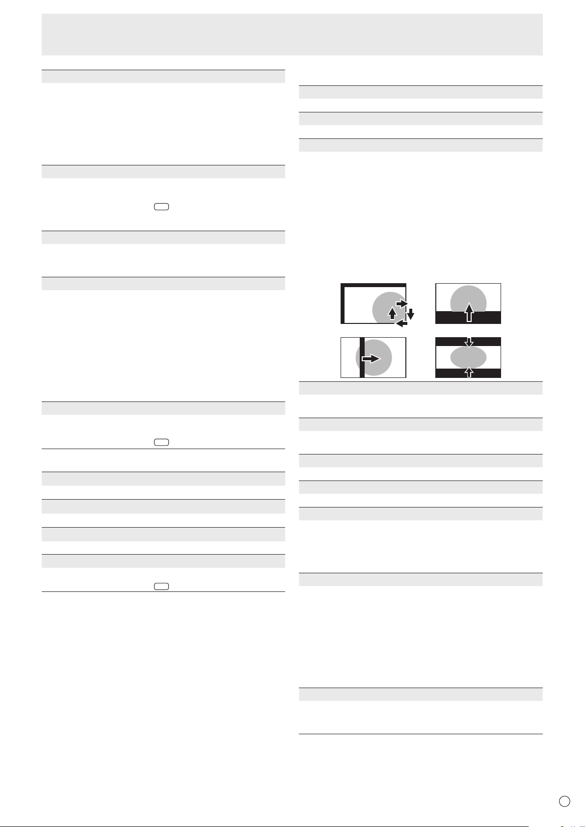
SCREEN MOTION
Residual images are reduced by moving the screen.
PATTERN1 ......... The whole screen moves vertically and
horizontally.
PATTERN2 ......... A black screen spreads from the bottom of
the screen and then shrinks to the bottom
of the screen.
PATTERN3 ......... A black bar moves from the left end to the
right end of the screen.
PATTERN4 .........Blackscreensappearfromboththe
top and bottom of the screen, and the
displayed image is compressed into the
centraleld.
PATTERN1 PATTERN2
PATTERN4PATTERN3
MOTION TIME 1
Specifyatimeperiod(operatinginterval)untilSCREEN
MOTION starts.
MOTION TIME 2
SpecifyatimeperiodduringwhichSCREENMOTION
operates (time period during which the screen will move).
MONAURAL AUDIO
Outputs audio signals as monaural.
LANGUAGE
Sets the display language for the menu screen.
POWER ON DELAY
You can delay the screen display after the monitor is turned
on.Theperiodcanbesetupto60secondsinunitsofone
second.Whenthisfunctionisactivated,thepowerLED
ashes(atapprox.1secondinterval)inorange.Thisfunction
isdisabledwhen0isspecied.
STANDBY MODE
WhenSTANDARDisselected,startuptimefromstandby
mode is reduced. Note, however that, more power will be
consumed in standby mode.
WhenLOWPOWERisselected,currentconsumption
is reduced while the monitor is in standby mode. Note,
however, that the startup time from standby mode becomes
longer.
IfsettoLOWPOWER,certainRS-232Ccommandscannot
be used in standby mode, and control via LAN will be
disabled.
OFF IF NO OPERATION
Determineswhetherornottosetthemonitortogointo
standby mode when there is no operation from the remote
controlunit,RS-232Ccommands,orLANforover4hours.
Menu Items
26
E
Menu Items
n
OPTION
DATE/TIME SETTING
Set the date and time. Press
or
to select the date
and time, and press
or
to change the numerical
values.
Setthedatein“Month/Day/Year”order.
Setthetimeona12-hourbasis.(Factorydefault)
DATE/TIME FORMAT
Sets the date/time display format.
DATE ..................MM/DD/YYYY
DD/MM/YYYY
YYYY/MM/DD
(YYYY:Year,MM:Month,DD:Day)
TIME ...................Select12-or24-hourtime.
SCHEDULE (See page 29.)
You can turn the power on/off and change the screen
brightnessataspeciedtime.
INPUT SELECT
SelecttheinputmodetobeusedinPCD-Subinputterminal,
PC/AVDVI-Dinputterminal,PC/AVHDMIinputterminaland
PCRGB/AVcomponentinputterminals.
ForD-SUB,selectSETafterselectingtheinputmode,and
then
press
MENU
.
D-SUBandBNCcannotbesettoAVCOMPONENTatthe
same time.
IfD-SUBissettoAVVIDEO,theAVVIDEOinputterminal
cannotbeusedforBNC.
AUDIO SELECT
Selects the terminal used to input audio signals in each input
mode.
INPUT SIGNAL (PC D-SUB/PC RGB)
IfacomputerconnectedtothePCD-sub/PCRGBinput
terminal outputs any of the following resolutions, make a
selection from the following options.
480LINES ..........AUTO,640x480or848x480
768LINES ..........AUTO,1024x768,1280x768,or1360x768
1050LINES ........1400x1050or1680x1050
ZOOM2SPECIALSETTING(See page 28.)
SCAN MODE (AV input)
SetsthescanmodeusedforAVmodeinput.
MODE1 ...............Over-scandisplay
MODE2 ...............Under-scandisplay
MODE3 ...............Under-scandisplaywhentheinputsignal
is1080i/p.Otherwise,over-scandisplay
*
EvenwhenMODE1isselected,under-scandisplayisusedwhen
theinputsignalis1080i/pandthescreensizeisDotbyDot.
POWER MANAGEMENT
POWERMANAGEMENTdetermineswhetherornotto
switch modes from no signal to the input signal standby
mode.
COLOR SYSTEM (AV S-VIDEO/AV VIDEO)
SelectthecolorsystemoftheAVequipmentwhichis
connectedtoAVS-videoandAVvideoinputterminal.(AUTO
/PAL/PAL-60/SECAM/NTSC3.58/NTSC4.43)
WhenAUTOisselected,thecolorsystemisautomatically
set according to the input signal.
HOT PLUG CONTROL
SetswhethertousehotplugcontrolforthePC/AVHDMI
andPC/AVDVI-Dinputterminals.
RS-232C/LAN SELECT
Selects the method with which to control the monitor from
the computer.
ID No. SET
AssignsIDnumberstomonitorsconnectedinadaisychain
(seepage33),usingtheRS-232cables.
Thenumbers1to255areavailableforIDnumbers.
If“0”isset,thesystemregardsthisasthestatewherenoID
number is set.
AUTO ASSIGN ID No.
IDNo.tobeusedwillbeautomaticallyassignedwhen
multiplemonitorsareconnectedwithRS-232C.
Select ON, then press
MENU
.
Performoperationsusingtherstmonitorinthedaisychain.
BAUD RATE
SelectsthecommunicationspeedusedforRS-232C
communication.
LAN SETUP
Conguresthesettingstocontrolthemonitorfromthe
computer via LAN. (See page 43.)
AUTO ASSIGN FIXED IP ADDR.
CanbeenabledwhenRS-232C/LANSELECTisLANand
theDHCPCLIENTisOFF.
SetDHCPCLIENTtoOFFforthemonitorconnectedtothe
RS-232Coutputterminalandthedaisychainofconnected
monitorsthatfollows.FixedIPaddressesareautomatically
allocated.
If the IP address is a duplicate with a network device other
than a monitor, individually change the IP address.
SPEAKER SELECT
Selects the speaker to be used.
HDMI AUTO VIEW
WhenONisselected,thescreensizeisadjusted
automaticallyaccordingtothescreensizecontrolsignal
includedinthevideosignalinputfromtheAVHDMIinput
terminal.
COPY SETTING VALUE
Whenthemonitorhasbeenconnectedtomultiplemonitors
byRS-232C,thesettingsinthemonitorcanbecopiedtothe
monitorconnectedtotheRS-232Coutputterminalandto
the daisy chain of connected monitors that follows.
SelectsthesettingstocopywithCOPYSETTINGVALUE
TARGET.
“PICTURE”ONLY .....CopiesthePICTUREmenusettings.*
ALL ...........................Copiesallthesettings.*
SelecttheIDNo.ofthemonitorthatyouwouldlikecopyto
withCOPYTOIDNo.,thenselectCOPYandpress
MENU
.
If you select ALL, settings will be copied to all monitors.
WhenyouwouldliketoconrmtheIDNo.thatissettothe
monitor,selectIDNo.DISPLAYandpress
.TheIDNo.
will be displayed on the screen.
*CertainsettingdetailssuchasANALOGGAIN,ANALOG
OFFSET,andDISPLAYCOLORPATTERNcannotbe
copied.
LOGO SCREEN
Sets whether or not to display the logo screen.

27
E
Menu Items
AUDIO OUTPUT (RCA)
Sets the volume of sound output from the audio output
terminals.
WhensettoVARIABLE2,soundwillnotbeoutputfromthe
built-inspeakerortheexternalspeakerterminal.
VARIABLE1 ........ YoucanadjustthevolumeusingVOLUME.
VARIABLE2 ........ YoucanadjustthevolumeusingVOLUME.
FIXED .................Fixesthesounds.
AUDIO LEVEL (STEREO MINI)
Selects the maximum audio input level of the audio input
terminal.
SELF ADJUST
On a PCD-SUB/PCRGB screen, specify whether to
performscreenadjustmentautomaticallyornot.WhenON
isselected,thescreenisautomaticallyadjustedwhenits
resolutionis800x600orhigherandthetimingofinput
signalschanges.“ADJUSTING”appearsonthescreen
duringtheadjustment.Forimageswithblackedges,etc.,
dependingonthesignal,adjustmentmaynotbepossible.
InthiscaseselectOFF.(Performmanualadjustmentofthe
screen.)
AUTO INPUT CHANGE
Specifywhethertochangeinputsautomatically.WhenONis
selected and no signal is present in the selected input mode,
AUTOINPUTCHANGEautomaticallychangestheselected
mode to another mode where a video signal is present.
Whenvideosignalsexistinmultipleinputmodes,the
switching priority is as follows:
PCD-SUB,PCHDMI,AVHDMI,AVCOMPONENTandAV
VIDEO
WhenthePN-ZB01(optional)isattached:
PCDVI-D,PCHDMI,PCD-SUB,PCRGB,AVDVI-D,AV
HDMI,AVCOMPONENT,AVS-VIDEOandAVVIDEO
(Inputmodeswitchingmaytake15secondsormore,
dependingontheconnectedequipment.Inputsignals
may not be detected properly and a priority may change,
dependingontheconnectedequipmentorvideosignals.)
TOUCH PANEL MODE (PC input)
Whentheresolutionis1920x1080,settingthistoON
improves touch panel tracking.
Whentwoscreensaredisplayed,orwhenV-POSorV-SIZE
isadjustedontheSCREENmenu,thescreenmaybecome
distorted.Inthisvent,settoOFF.
n
PIP/PbyP
PIP MODES
Sets the display method.
OFF .........Displaysonescreen.
PIP ...........Displaysasubscreeninsideamainscreen.
PbyP ........Displaysamainscreenandasubscreeninaline.
PbyP2 ......
Displaysamainscreenwhichmeasures1280pixels
in the longest direction and a sub screen in a line.
PIP SIZE
SetsthesizeofthesubscreeninPIPmode.
PIP H-POS
AdjuststhehorizontalpositionofthesubscreeninPIPmode.
PIP V-POS
AdjuststheverticalpositionofthesubscreeninPIPmode.
PIP BLEND
In PIP mode, use this menu item to display the sub screen
transparently.
PIP SOURCE
Selects the input signal of the sub screen in PIP, PbyP, or
PbyP2 mode.
SOUND CHANGE
Sets the sound which is output in PIP, PbyP, or PbyP2 mode.
If the main screen is displayed as a full screen by the AUTO
OFFfunction,thesoundforthemainscreenisoutputeven
whenthesoundforthesubscreenisspecied.
MAIN POS
Sets the position of the main screen in PbyP or PbyP2 mode.
PbyP2 POS
Sets the position of the sub screen in PbyP2 mode.
AUTO OFF
Sets the display method when no signals for the sub screen
are input in PIP, PbyP, or PbyP2 mode.
MANUAL .......
Displaysamainscreenandablacksubscreen.
AUTO ............ Displaysthemainscreenasafullscreen.
TIPS
• WhenWHITEBALANCEissettoTHRU,BLACKLEVEL,
CONTRAST,TINT,COLORS,RGBINPUTRANGE,
GAMMAandCOPYTOUSERcannotbeset.
• IfCOLORMODEissettosRGB,thefollowingitemscannot
be set.
WHITEBALANCE,PRESET,USER,COPYTOUSER,and
GAMMA
• WhentheCOLORMODEissettoVIVID,GAMMAcannot
beadjusted.
• STANDBYMODEcannotbesettoLOWPOWERwhen
SCHEDULEiseffectiveorwhenOFFisselectedforLEDin
FUNCTION.
• Whendisplayingthecolorpattern,itispossibletoadjust
certainitemsofthePICTUREmenu.
Non-adjustableitemscannotbeselected.
AudioinputfromtheHDMIinputterminalisalsonotoutput.
28
E
Menu Items
n
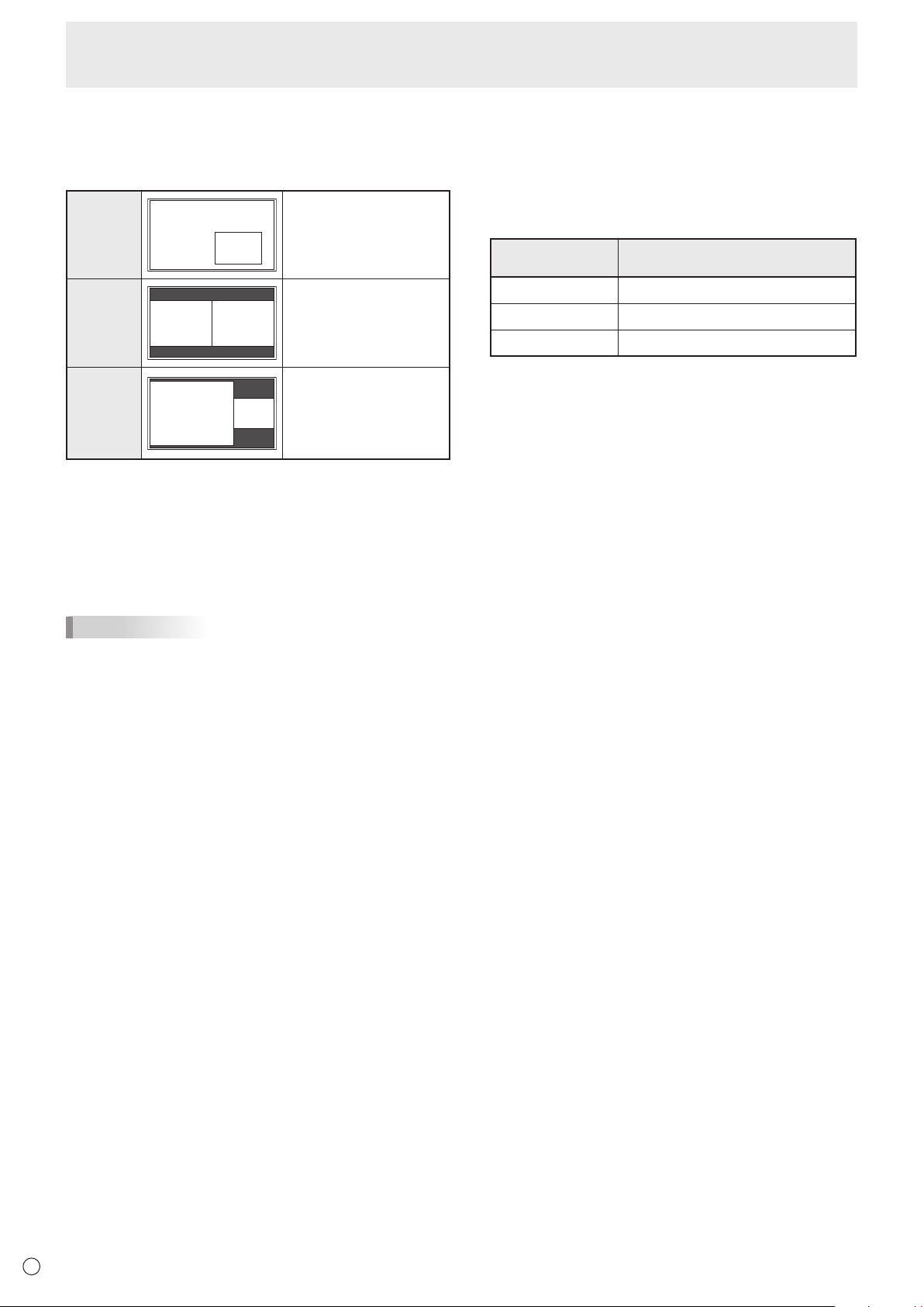
Dual screen display
YoucandisplaythescreensofthePCinputsignalandAV
input signal simultaneously.
Setthisfunctionwith“PIPMODES”inthePIP/PbyPmenu.
PIP
Main screen
Sub
screen
A sub screen is displayed
inside a main screen.
PbyP
Main
screen
Sub
screen
A main screen and a sub
screen are displayed in a
line.
PbyP2
Main screen
Sub
screen
Displaysamainscreen
whichmeasures1280
pixels in the longest
direction and a sub
screen in a line.
* Thecurrentlyselectedinputsignalisdisplayedonthemain
screen.
* Youcannotsimultaneouslydisplaythescreensofsignals
ofthesametype,suchastwotypesofPCinputsignalsor
twotypesofAVinputsignals.
* Thedualscreendisplaycannotbeusedwiththe
combinationofPCDVI-DandAVHDMIorofAVDVI-Dand
PCHDMI.
TIPS
• Youmightinfringeonacopyrightoftheauthorwhichis
protected by copyright law when you display the images of
thecomputerscreenandtelevision/VCRsimultaneouslyfor
prot-makingortoshowtheimagetothepublic.
• Thescreensizefordual-screendisplayisthesameas
thescreensizeforsingle-screendisplay.TheDotbyDot
screenisdisplayedinNORMALsizeexceptwhenitisset
as the PIP main screen.
• Whendual-screendisplayisselected,theSCREEN
MOTION function is disabled.
• Whendual-screendisplayisselected,theAUTOINPUT
CHANGEfunctionisdisabled.
• Whendual-screendisplayisselected,theINPUTSELECT
options cannot be set.
• Whenaninterlacedsignal(1080i,480i,video,S-Video)is
inputtothesubscreen,horizontallinesmayicker.Ifthis
happens, display the image on the main screen.
n
ZOOM2 SPECIAL SETTING
If you connect a laptop computer with any of the following
screen resolutions and black bands appear around the
screen,setZOOM2SPECIALSETTINGofINPUTSIGNALon
theOPTIONmenutoONandthenselectZOOM2intheSIZE
setting.
This displays the area inside the black band.
Laptop computer
resolution
Correspondingsignal*
1
1280x800 1280x1024,1280x960,1400x1050*
2
1280x600 1280x720
1024x600 1024x768
*1:Thissettingiseffectiveonlywhenthescreenresolution,
including the black band, is one of the resolutions listed
above.
*2:Usetheautomaticscreenadjustment.
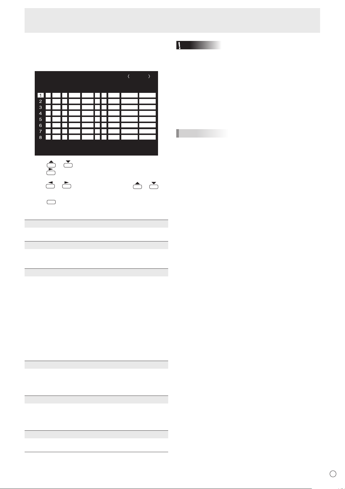
29
E
n
SCHEDULE
You can set the time to switch the monitor on and off.
Setthisfunctionwith“SCHEDULE”intheOPTIONmenu.(See
page 26.)
-
:
– – – – – – – – – – – –– – – – –
SCHEDULE
No.
POWERDAY OF THE WEEK
TIMEINPUT BRIGHT
– –
/
– –
/
– – – – – – –
– –
:
– –
:
– – – –
PC D-SUB
(1)
–
-
:
– – – – – – – – – – – –– – – – ––
-
:
– – – – – – – – – – – –– – – – ––
-
:
– – – – – – – – – – – –– – – – ––
-
:
– – – – – – – – – – – –– – – – ––
-
:
– – – – – – – – – – – –– – – – ––
-
:
– – – – – – – – – – – –– – – – ––
-
:
– – – – – – – – – – – –– – – – ––
(5)(2)(3) (4)(6)
OK···[MENU]
1920x1080
V: 60 Hz H: 67.5 kHz
1. Press or to select the SCHEDULE number, and
press
.
2. Set the SCHEDULE. (See the description below.)
Press
or to select items, and press or to
change the setting.
3. Press
MENU
.
SCHEDULEbecomeseffective.
(1)
●:SCHEDULEeffective
-
:SCHEDULEnoteffective
(2) POWER
ON : Switchesthemonitoronatthespeciedtime.
OFF: Switchesthemonitoroffatthespeciedtimeandputs
the monitor in standby mode.
(3) DAY OF THE WEEK
SpeciesthedayoftheweektoexecutetheSCHEDULE.
0:ONLYONCE
ExecutestheSCHEDULEonceonthespeciedday.
SpecifythedayoftheweektoexecutetheSCHEDULE.
1:EVERYWEEK
ExecutestheSCHEDULEonthespecieddayoftheweek
every week. Specify the day of the week to execute the
SCHEDULE.
Periodicsettingsuchas“MondaythroughFriday”isalso
possible.
2:EVERYDAY
ExecutestheSCHEDULEeverydayregardlessoftheday
of the week.
(4) TIME
SpeciesthetimetoexecutetheSCHEDULE.
Setthetimeona12-hourbasis.(Factorydefault)
Canbeenteredas24-hourtimeusingtheTIMEsettingin
DATE/TIMEFORMAT.
(5) INPUT
Speciestheinputmodeatpower-on.Whennotspecifying,
thescreenatthepreviouspower-offappears.
InputmodesdisplayedonDVI,HDMI,BNCandD-SUB
dependonINPUTSELECTsettings.
(6) BRIGHT
Sets the brightness when changing the screen brightness at
aspeciedtime.
Menu Items
Caution
• Donotswitchoffthemainpoweraftersettingthe
SCHEDULE.
• Specifythecorrectdateandtime.(Seepage26.)
SCHEDULEdoesnotfunctionunlessthedateandtimeare
specied.
• Checkregularlythatthesetdateandtimearecorrect.
• WhenSTANDBYMODEisLOWPOWER,SCHEDULE
cannot be set.
• Whenatemperatureabnormalityoccursandthebacklight
brightness is reduced, the brightness is not changed even
ifaschedulesettoBRIGHTisexecuted.
TIPS
• Upto8SCHEDULEitemscanberegistered.
• SettingtheSCHEDULEashesthepowerLEDalternately
in red and orange in standby mode.
• ASCHEDULEthathasalargenumberhasprecedence
over that of a small number when schedules overlap.
• IfD-SUBofINPUTSELECTontheOPTIONmenuissetto
AVVIDEO,theinputmodewillswitchtoAVVIDEO(D-SUB)
regardlessifsettoD-SUBorVIDEO.
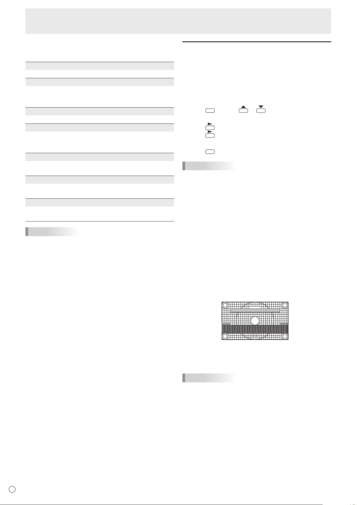
30
E
n
ADVANCED items (AV input) (See page 24
for additional Menu item details.)
FLESH TONE
Adjustthehuecontrol.
3D-NR
Reduce the noise of playback images on video.
Settingahigherlevelreducesmorenoise.However,itmay
cause blurring on an image.
MPEG-NR
Reduce block noise caused by digital compression.
3D-Y/C (AV VIDEO)
Specifywhethertoperform3-dimensionY/Cseparation.
Ifdotinterferenceorcross-colorisoccurringinfast-motion
scenes,selecting“OFF”mayimprovetheimagequality.
C.M.S.-HUE
Adjustscolortonewith6colorsofR(red),Y(yellow),G
(green),C(cyan),B(blue),andM(magenta).
C.M.S.-SATURATION
Adjustscolorvividnesswith6colorsofR(red),Y(yellow),G
(green),C(cyan),B(blue),andM(magenta).
C.M.S.-VALUE
Adjustscolorbrightnesswith6colorsofR(red),Y(yellow),
G(green),C(cyan),B(blue),andM(magenta).
TIPS
• WhenFLESHTONEissettoLOWorHIGH,C.M.S.-HUE/
-SATURATION/-VALUEcannotbeset.
Adjustments for PC screen display
n
Automatic adjustment
WhenyouusethePCD-subinputterminalorPCRGBinput
terminalstodisplayaPCscreenforthersttime,orwhen
youchangethesettingofthePC,usetheautomaticscreen
adjustment.
1. Switch the input to PC D-SUB or to PC RGB and display
the adjustment pattern. (See the description below.)
2. Press
MENU
and use or to display the SCREEN
menu.
3. Press and select “AUTO”.
4. Press
.
Theautomaticadjustmentiscompleteinseveralseconds.
5. Press
MENU
twice to close the menu screen.
TIPS
• Ifthescreencannotbeadjustedproperlywithone
automaticadjustment,repeattheautomaticadjustmenttwo
orthreetimes.Trymanualadjustmentifnecessary.
n
Screen display for adjustment
BeforemakingadjustmentsintheSCREENmenuor
PICTUREmenu,displayanimagetobrightentheentire
screen.IfyouareusingaWindowsPC,usetheadjustment
patternonthesuppliedCD-ROM.
Opening the adjustment pattern
ThefollowingexampleisperformedinWindows7.
1. Load the supplied CD-ROM into the computer’s CD-
ROM drive.
2. Open [CD Drive] in [Computer].
InWindowsXP,open[CDDrive]in[MyComputer].
3. Double-click [Adj_uty.exe] in the [Monitor] folder.
Theadjustmentpatternwillappear.
Adjustthescreenautomaticallyormanually.
4. When adjustment is nished, press the [Esc] on the
computer’s keyboard to quit the adjustment program.
5. Eject the CD-ROM from the CD-ROM drive.
TIPS
• Ifthedisplaymodeonthecomputeryouareusingis
65,000colors,thecolorlevelsinthecolorpatternmay
appear differently or grayscale may appear to be colored.
(Thisisduetothespecicationsoftheinputsignalandis
not a malfunction.)
Menu Items
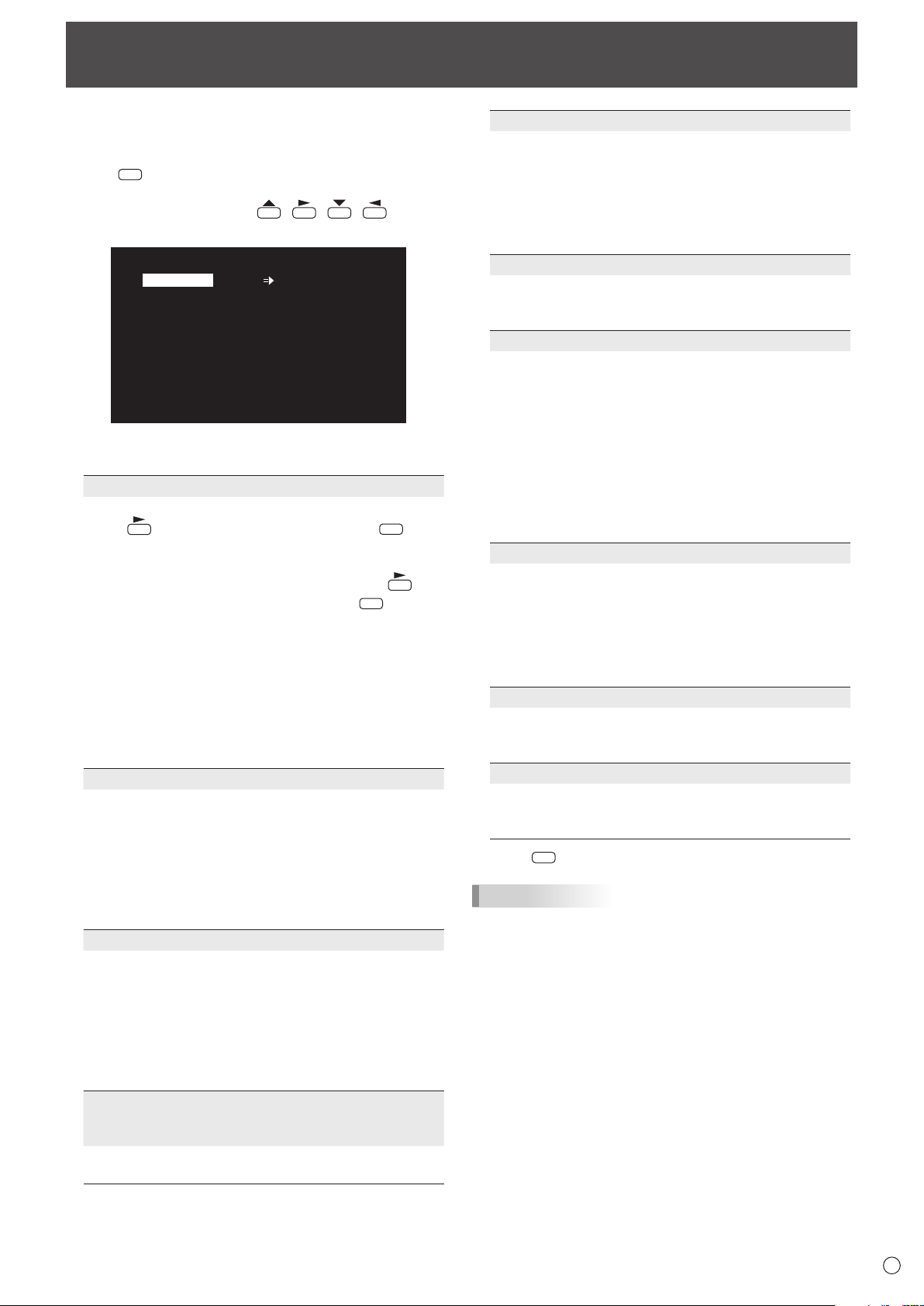
31
E
Youcanreturnthesettingstotheirfactory-presetvaluesand
restrict operations.
1. Hold
SIZE
down until “F” appears in the upper left
corner of the screen.
2. While “F” appears, press
, , , in that
order.
▲
▲▲▲▲▲▲▲
▲ ▲ ▲ ▲ ▲ ▲ ▲
OFF
UNLOCKED
ON1
ON
LED
OFF
MONITOR
FUNCTION
1/1
ALL RESET
ADJUSTMENT LOCK
ADJUSTMENT LOCK TARGET
RS-232C
OSD DISPLAY
LED
TEMPERATUREALERT
STATUSALERT
POWER BUTTON
CONTROLLER INPUT
END…[MENU]
3. Select and set the items.
ALL RESET
Resets the settings to the factory default settings.
Press
,selectALLRESET,andthenpress
MENU
.
Afterinitialization,turnthemainpowerswitchoffand
then back on.
WhenthePN-ZB01(optional)isattached,press ,
select the resetting method, and then press
MENU
.
ALLRESET1 ....Resets all the settings to the factory
default settings.
ALLRESET2 ....Returns all settings to the factory default
settings except for the following items:
LANSETUP,RS-232C/LANSELECT,
IDNo.SET,BAUDRATE,NETWORK,
MAIL,SERVICE&SUPPORT,and
SNMP (See page 26, and pages 47 to
50.)
ADJUSTMENT LOCK
You can disable operations on the monitor and the
remote control unit that use buttons.
OFF ...Enablesoperation.
ON1 ..Disablesalloperationsotherthanturningpower
on/offandFUNCTION.
ON 2 ..OnlytheFUNCTIONoperationisenabled.
DisablesalloperationsotherthanFUNCTION(not
even power on/off).
ADJUSTMENT LOCK TARGET
Sets the target to prohibit operation of with
ADJUSTMENTLOCK.
REMOTECONTROL ..... Prohibits remote control
operation
MONITORBUTTONS ... Prohibits monitor button
operation
BOTH ............................. Prohibits remote control and
monitor button operation
RS-232C
(RS-232C/LAN when the PN-ZB01 (optional) is
attached)
SpecieswhethertoallowcontrolviaRS-232CorLAN
(see pages 32 and 43).
Initialization (Reset)/Functional Restriction Setting (FUNCTION)
OSD DISPLAY
Shows/hides the menu, modes, and messages.
TheFUNCTIONscreencannotbehidden.
ON1 .............. Shows all menus, modes and messages.
ON 2 .............. Hidesmessagesautomaticallydisplayed
by the display. Shows messages during
operation.
OFF ............... Hidesallmenus,modesandmessages.
LED
SpecieswhethertolightthepowerLED.
OFFcannotbeselectedwhenSTANDBYMODEisLOW
POWER.
TEMPERATURE ALERT
Selectsthenoticationmethodforanabnormal
temperature.
OFF .............. Donotnotifyaboutanabnormal
temperature.
OSD&LED .. Whenanabnormaltemperatureis
detected,thepowerLEDashesinred
and green alternately and the screen
displaysamessage:TEMPERATURE.
LED............... Whenanabnormaltemperatureis
detected,thepowerLEDashesinred
and green alternately.
STATUS ALERT
Selectsthenoticationmethodforahardwareerror.
OFF .............. Donotnotifyabouttheerror.
OSD&LED .. Whenahardwareerrorisdetected,the
powerLEDashesinredandthescreen
displaysamessage:STATUS[xxxx].
LED............... Whenahardwareerrorisdetected,the
powerLEDashesinred.
POWER BUTTON
Normally, leave this setting as MONITOR.
Whenusinganoptionalpart,ifinstructionappears,
change the setting accordingly.
CONTROLLER INPUT
Normally, you do not need to change this setting.
Whenusinganoptionalpart,ifinstructionappears,
change the setting accordingly.
4. Press
MENU
to return to the normal screen.
TIPS
• Whenbothabnormaltemperatureandhardwareerrorare
detected,thehardwareerrornoticationoverrides.
• IfTEMPERATUREALERTorSTATUSALERTissetto
OSD&LED,alertmessageswillappeareveniftheOSD
DISPLAYissettoON2orOFF.
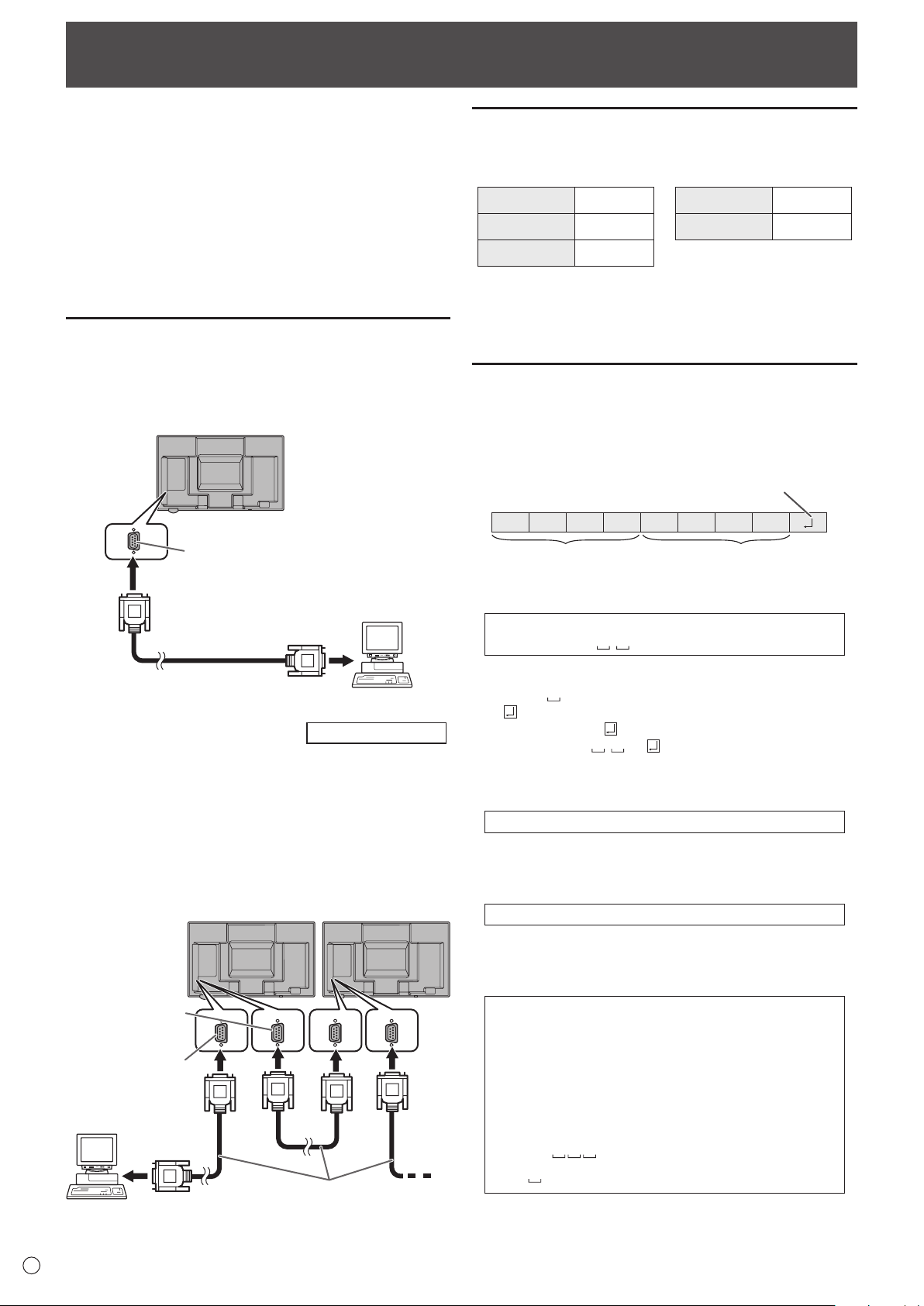
32
E
Controlling the Monitor with a PC (RS-232C)
YoucancontrolthismonitorfromaPCviaRS-232C(COM
port)onthePC.
You can also connect multiple monitors via a daisy chain by
usingaPC.ByassigningIDnumberstoeachmonitor(see
page33),youcanmakeinputmodeselection/adjustmentor
cancheckthestatusofaspecicmonitor.
Precautions when the PN-ZB01 (optional) is attached
• TocontrolthemonitorviaRS-232C,setRS-232C/LAN
SELECTtoRS-232C.
• YoucannotuseRS-232CandLANcontrolsimultaneously.
PC connection
n
One-to-one connection with a PC
ConnectwithRS-232straightcablebetweenthePC’sCOM
port(RS-232Cconnector)andtheRS-232Cinputterminalon
the monitor.
RS-232 straight cable
(commercially available)
To COM port
PC
RS-232C input terminal
n
Daisy chain connection…
Advanced operation
ConnectwithRS-232straightcablebetweenthePC’sCOM
port(RS-232Cconnector)andtheRS-232Cinputterminalon
therstmonitor.
Next,connectRS-232straightcabletotherstmonitor’s
RS-232Coutputterminalandtothesecondmonitor’s
RS-232Cinputterminal.Connectinthesamewaytothethird
andsubsequentmonitors.
Upto25monitorscanbeconnected.(Dependingonthe
length of the cable used and the surrounding environment.)
To COM port
RS-232 straight cables
(commercially available)
PC
First monitor
Second monitor
RS-232C
input terminal
RS-232C
output terminal
Communication conditions
SettheRS-232CcommunicationsettingsonthePCtomatch
the monitor’s communication settings as follows:
Baudrate *
Stop bit
1bit
Datalength 8 bits Flowcontrol None
Parity bit None
*SettothesamebaudrateastheBAUDRATEsettingof
SETUPmenu.(Initialsetting:38400bps)
*Whenconnectingmultiplemonitorsinadaisychain,setall
monitorstothesameBAUDRATE.
Communication procedure
n
Command format
WhenacommandissentfromthePCtothemonitor,the
monitor operates according to the received command and
sendsaresponsemessagetothePC.
C1 C2 C3 C4 P1 P2 P3 P4
Return code
Command field
(4 prescribed
alphanumerical characters
)
Parameter field
(4 character string comprised of:
0-9, +, -, space, ?)
Example:VOLM0030
VOLM
30
* Besuretoinput4charactersfortheparameter.Padwith
spaces (“
”) if necessary.
(“
”isareturncode(0D
H
,0A
H
or0D
H
))
Wrong :VOLM30
Right :VOLM 30
Wheninputtinganegativevalue,specifyanumericalvaluein
three digits.
Example:AUTR-005
DonotusespacesforMPOS,DATE,andSC01through
SC08.Specifyparametersusingaspeciednumberof
characters.
Example:MPOS010097
Ifacommandhas“R”listedfor“DIRECTION”inthe
“RS-232Ccommandtable”onpage36,thecurrentvaluecan
be returned by using “?” as the parameter.
Example:
VOLM???? ←
FromPCtomonitor(Howmuch
is current volume setting?).
30 ←
FrommonitortoPC(Current
volumesetting:30).
* IfanIDnumber(seepage33)hasbeenassigned
(Forexample,IDnumber=1).
VOLM
? ←
FromPCtomonitor.
30 001 ←
FrommonitortoPC.
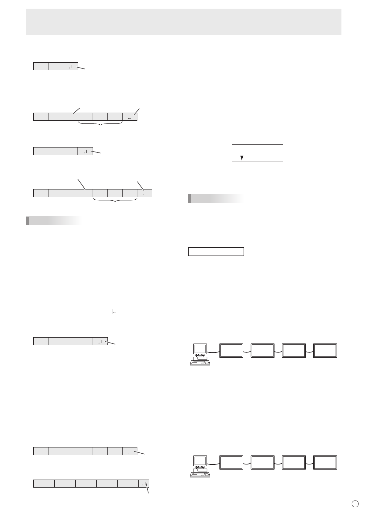
33
E
Controlling the Monitor with a PC (RS-232C)
n
Response code format
When a command has been executed correctly
O K
Return code
(0DH, 0AH)
A response is returned after a command is executed.
* IfanIDnumberhasbeenassigned
O K SPC 0 0 1
ID number of respondin
g
monitor
Space (20
H)
Return code
(0DH, 0AH)
When a command has not been executed
R R E
Return code
(0DH, 0AH)
* IfanIDnumberhasbeenassigned
R R E SPC 0 0 1
ID n
u
m
be
r
Space (20H)
Return code
(0DH, 0AH)
TIPS
• “ERR”isreturnedwhenthereisnorelevantcommandor
when the command cannot be used in the current state of
the monitor.
• Ifcommunicationhasnotbeenestablishedforreasons
suchasabadconnectionbetweenthePCandmonitor,
nothingisreturned(notevenERR).
• “ERR”maybereturnedwhenacommandcannotbe
received correctly due to interference from the surrounding
environment.
Please ensure that the system or software retries the
command if this occurs.
• IfnomonitorhasbeenassignedthedesignatedIDnumber
(e.g.ifthecommandIDSL0002
is used, but no monitor
withIDnumber:2isfound),noresponseisreturned.
If execution of the command is taking some time
I W T A
Return code
(0DH, 0AH)
Whenthefollowingcommandsareused,“WAIT”isreturned.
Inthiscase,avaluewillbereturnedifyouwaitawhile.Donot
send any command during this period.
NoIDnumberisattachedtoWAITresponse.
• CommandswhichreturnWAIT:
1. Whenrepeatercontrolisused
2. WhenanIDSLorIDLKcommandisused
3. Whenoneofthefollowingcommandsisused:RSET,
INPS,ASNC,WIDE,PXSL,POWR,AGIN,MWIN,
MWIP,MWPP
When control via RS-232C is locked (to prevent use)
using the operation lock function (see page 31)
E C D K O L
Return code
(0D
H, 0AH)
When RS-232C/LAN SELECT is set to LAN
U N S E L E C T E D
Return code
(0D
H, 0AH)
n
Communication interval
• AfterOKorERRisreturned,youmustsendthefollowing
commands.
Tosetatimeoutforthecommandresponse,specify10
seconds or longer.
Whenconnectingmultiplemonitorsinadaisychain,setthe
timeout to at least the product of the monitor’s position from
thecomputermultipliedby10seconds.
Example)3rdmonitorfromcomputer:30secondsorlonger.
• Provideanintervalof100msormorebetweenthe
command response and the transmission of the next
command.
VOLM0020
OK
INPS0001
WAIT
OK
Interval of 100 ms or more
TIPS
• WhenexecutingALLRESET,setthetimeoutperiodto30
seconds or longer.
• WhenturningthepoweronwhilethePOWERONDELAY
functionisinuse,setthetimeoutperiodtothePOWERON
DELAYperiod+10secondsorlonger.
Advanced operation
This section explains commands for daisy chain connection.
The basic communication procedure is the same as in the
“One-to-oneconnectionwithaPC”section.
n
ID numbers
YoucanassignauniqueIDnumbertoeachmonitor(see
page 26). This allows you to control a particular monitor in a
daisy chain of monitors.
YoucanassignIDnumberseitherfromthemenuscreenor
fromthePCusingRS-232cable.
[E
xamp
l
e
]
ID number: 1 ID number: 2 ID number: 3 ID number: 4
If monitors are connected as shown above, you can
execute commands like “Set the volume of the monitor with
ID4to20”.
WhendesignatingIDnumbersforasetofmonitorslinkedina
daisychain,youshouldbasicallyavoidanyduplicationofID
numbers.
IDnumbersdonothavetobeassignedinascendingorder
startingfromthePC.Theycanalsobeconnectedasshown
below.
[E
xamp
l
e
]
ID number: 3 ID number: 2 ID number: 4 ID number: 1
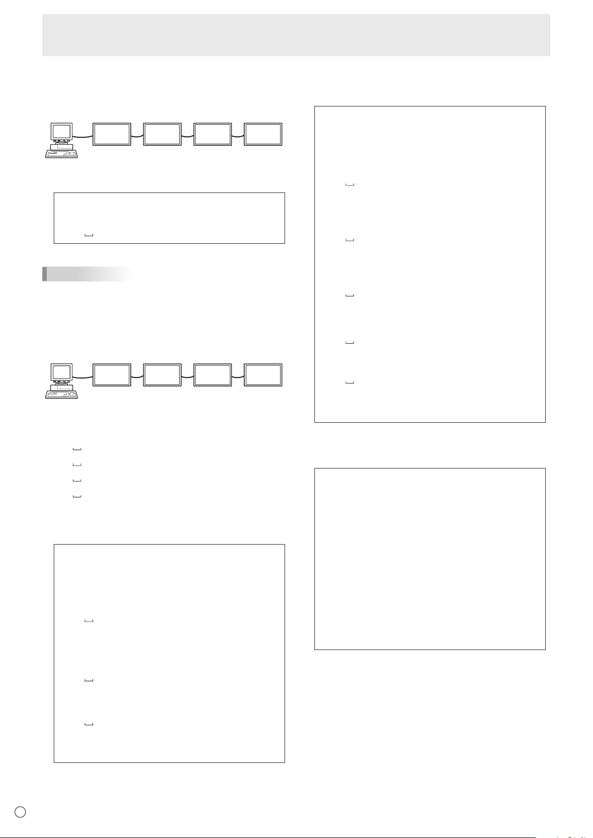
34
E
Controlling the Monitor with a PC (RS-232C)
n
Commands for ID control
The command examples shown on this page assume the
followingconnectionandIDnumbersetup.
ID number: 1 ID number: 2 ID number: 3 ID number: 4
IDST .........AmonitorreceivingthiscommandsetsitsownID
numberintheparametereld.
Example:
IDST0001
OK
001 ←
TheIDnumberofthismonitorissetto1.
TIPS
YoucanautomaticallyassignIDnumbersbyusingtheIDST
command with the Repeater control (see “Repeater control”
onpage35).
Forexample,usingthecommand“IDST001+”automatically
setstheIDnumbers,asshownbelow.
[E
xamp
l
e
]
ID number: 1 ID number: 2 ID number: 3 ID number: 4
IDST001+ ←
IDsettingcommandwithrepeatercontrol
WAIT
OK
001 ←
“OK”responsefromIDnumber:1
OK 002 ←
“OK”responsefromIDnumber:2
OK 003 ←
“OK”responsefromIDnumber:3
OK 004 ←
“OK”responsefromIDnumber:4(End)
IDSL ........TheparameterofthiscommandsetstheIDnumber
ofthemonitor.Themonitorissubjecttothenext
command.
Example:
IDSL0002 ←
The next command is for the monitor
withIDnumber:2.
WAIT ←
SearchingformonitorwithIDnumber:
2
OK 002 ←
FoundmonitorwithIDnumber:2
VOLM0030 ←
SetsvolumeofmonitorwithID
number:2to30.
WAIT ←
Processing
OK 002 ←
OKresponsefrommonitorwithID
number: 2
VOLM0020 ←
Setsvolumeto20.
OK 001 ←
ThevolumeofthemonitorwithID
number:1(theonedirectlyconnected
tothePC)issetto20.*
* TheIDSLcommandiseffectiveonlyonce,forthe
immediately succeeding command.
IDLK ........
TheparameterofthiscommandsetstheID
numberofthemonitor.Themonitorissubjecttoall
subsequentcommands.
Example:
IDLK0002 ←
Followingcommandsareforthemonitor
withIDnumber:2.
WAIT ←
SearchingformonitorwithIDnumber:
2
OK 002 ←
FoundmonitorwithIDnumber:2
VOLM0030 ←
SetsvolumeofmonitorwithID
number:2to30.*
WAIT ←
Processing
OK 002
VOLM0020 ←
SetsvolumeofmonitorwithID
number:2to20.*
WAIT
OK
002
IDLK0000 ←
CancelingxedIDnumbersetting
WAIT ←
CancelingIDLK
OK 002 ←
Cancelationcomplete
VOLM0010
OK
001 ←
ThevolumeofthemonitorwithIDnumber:
1(theonedirectlyconnectedtothePC)is
setto10.(IDLKiscanceled.)
* TheIDLKcommandremainseffectiveuntilitis
canceled, or power is shut off.
IDCK ........ProvidesscreendisplayoftheIDnumbercurrently
assignedtoamonitor,andtheIDnumbercurrently
setforIDLK(ifany).
Example:
(AfterexecutingIDLK0002)
IDCK0000
←
(Parameter has no meaning.)
ID:001IDLK:002
←
Returnedresponse.TheID
number is also displayed on the
monitor screen.
IDCK000+
←
Repeater control. (If a command
isusedwithrepeatercontrol,ID
designationusingIDSLorIDLK
is canceled.)
WAIT
ID:001IDLK:000
ID:002IDLK:000
ID:003IDLK:000
ID:004IDLK:000
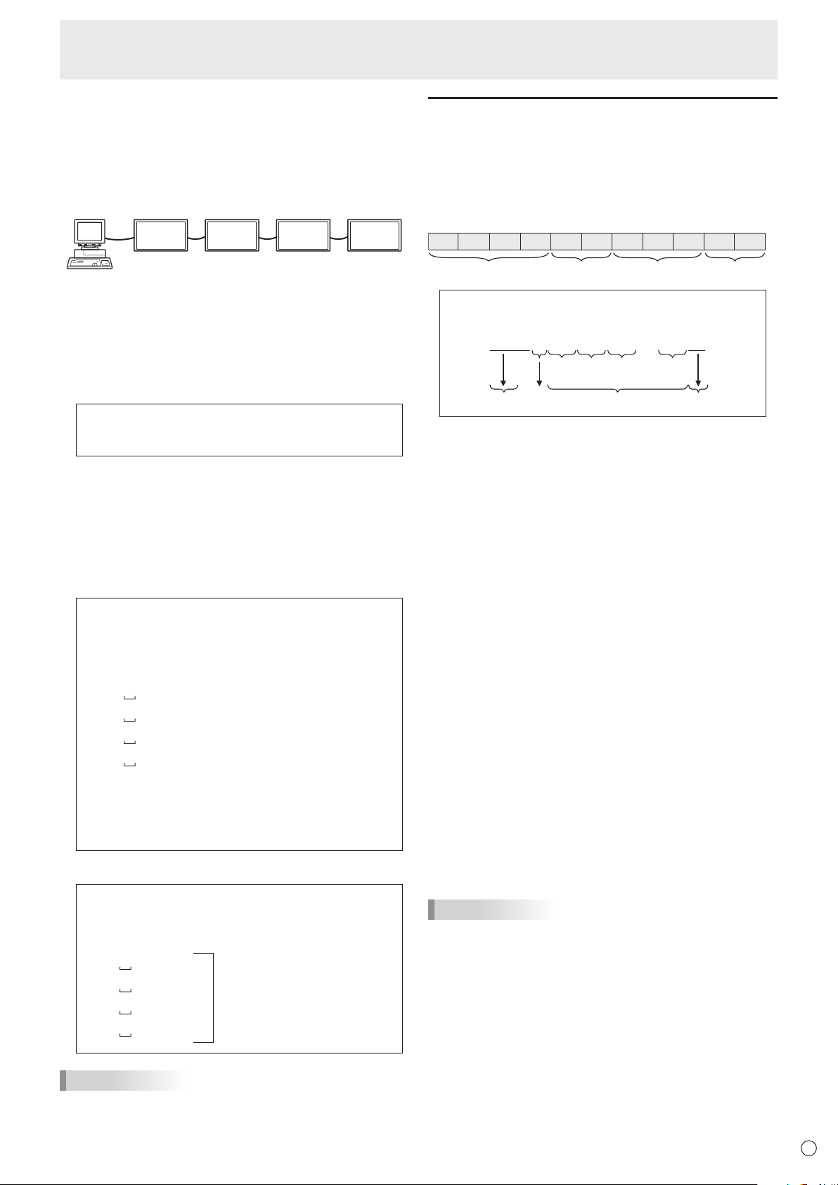
35
E
Controlling the Monitor with a PC (RS-232C)
n
Repeater control
This system has a function to allow setting of multiple
monitors connected in a daisy chain using a single command.
This function is called repeater control. You can use Repeater
controlfunctionwithoutassigningIDnumbers.
[E
xamp
l
e
]
Set 1
Set 2 Set 3Set 4
* Ifmonitorsareconnectedasshownabove,youcan
execute a command like “Set all monitors’ input settings to
PCD-SUB”.
n
Repeater control command
RepeatercontrolisachievedbysettingtheFOURTH
CHARACTERoftheparameterto“+”.
Example:
VOLM030+ ←
Setsvolumeofallmonitorsto30.
In repeater control, responses are returned by all the
connected monitors.
If you want to determine that a value has been returned by a
specicset,assignIDnumberstoeachmonitorinadvance.
Whensomemonitorsdonotreturntheirresponses,the
probable cause is that the monitors could not receive the
commandorcommandprocessingisnotcomplete.Donot
send a new command.
Example: (When4monitorsareconnected,and
assignedIDnumbers:1through4)
VOLM030+
WAIT
OK
001
OK
002
OK
003
OK
004 ← If 4 monitors are connected in
a chain, reliable operation can
be ensured by sending a new
command only after a reply
has been returned by 4th (last)
monitor.
Repeater control can also be used for reading settings.
Example:
VOLM???+
WAIT
10
001
Volumesettingsforall
monitors are returned.
20
002
30
003
30
004
TIPS
• IfrepeatercontrolisusedduringIDdesignation(IDSL,
IDLK),theIDdesignationiscanceled.
Setting of the GAMMA user data
n
To transfer the GAMMA user data
Usetheuserdatatransfercommands(UGRW,UGGWand
UGBW).ForeachoftheR,GandBcolors,dividethetotal
512piecesofuserdatainto16blocks,andtransfer32pieces
of data with each command.
C1 C2 C3 C4 P1 P2 P3 P4
…
S1 S2
Command field
Block number (01 to 16)
Data fieldChecksum field
Example:Totransferthedataofblock1(0to31levels)
of red (R) data
UGRW01000000010002 … 0031C0
Command
Block number
32 pieces of data Checksum
One piece of data consists
of 4 digits.
* Ifdataislessthan4digits,adda“0”(zero)tomakeit4
digits.
* Thechecksumeldisthecharacterstring(ASCII)dataof
lower-orderonebytewhichindicatesthesumoftheblock
numberand32piecesofdatainhexadecimal(0toF).
n
Saving the GAMMA user data
Usetheuserdatasavecommand(UGSV)tosavethe
transferred user data in the monitor.
If the data is not saved, it will be cleared when:
• Themainpowerswitchisoff
• STANDBYMODEisLOWPOWERandthemonitorenters
standby mode
n
Activating the GAMMA user data
Toactivatethetransferreduserdata,selectUSERforGAMMA
ofthePICTUREmenu,orsendthecorrespondingRS-232C
command.
n
Checking the GAMMA user data
Usetheuserdatareadcommands(UGRR,UGGRand
UGBR)toreturn512piecesofuserdataforeachoftheR,
GandBcolors.Dividethedatainto16blocksandreturn32
pieces of data with each command. The value to be returned
is not the value stored in the monitor, but the value in the
temporary memory for display. (These values are the same
whentheuserdatasavecommand(UGSV)abovehasbeen
sent.)
TIPS
• TheuserdataisnotinitializedbyRESETofthePICTURE
menu.Toinitializetheuserdata,useALLRESETofthe
FUNCTIONmenu.
TheGAMMAuserdatainitializecommand(UGRS)allows
theinitializationoftheuserdataonly.
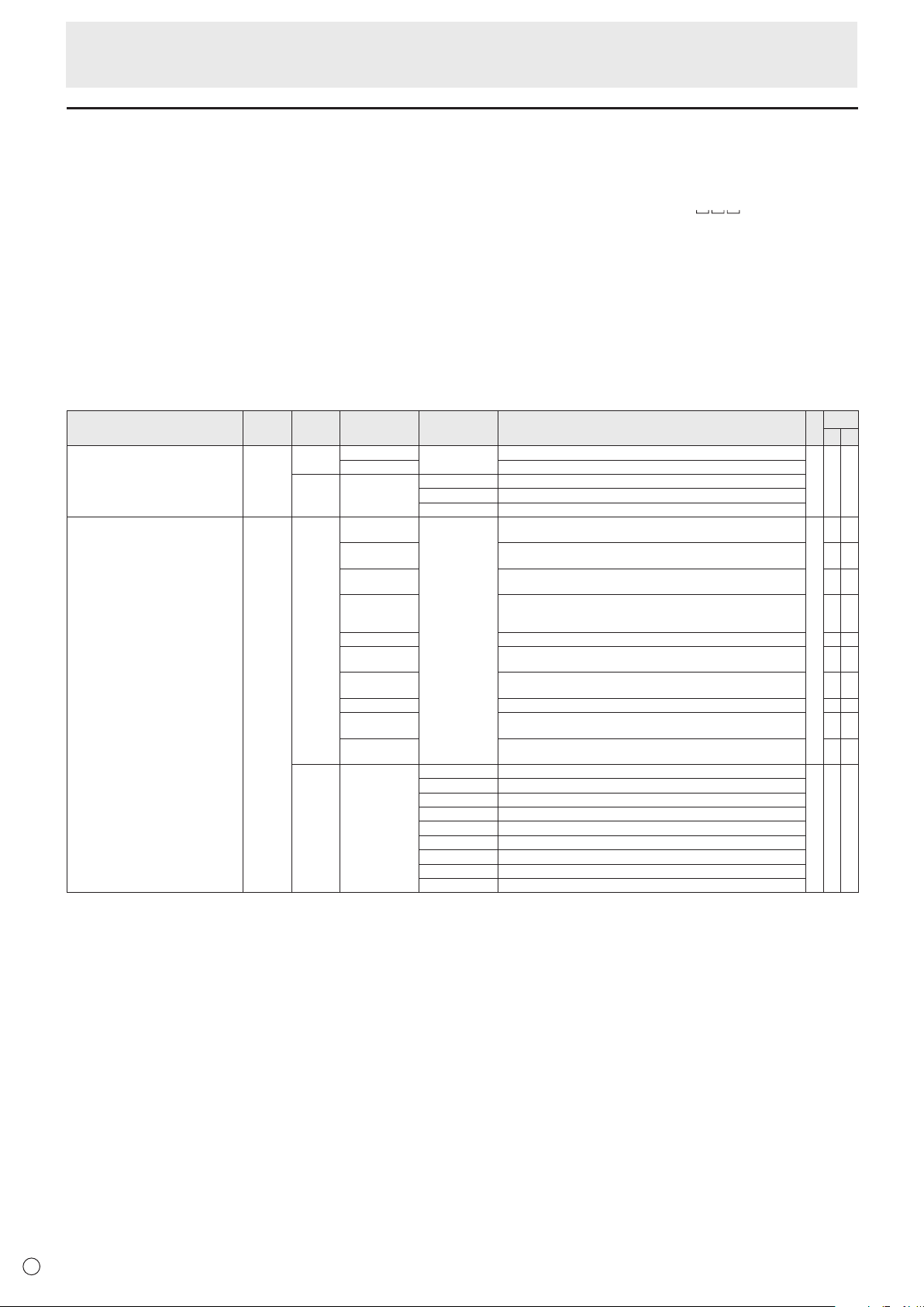
36
E
RS-232C command table
How to read the command table
Command: Commandeld(Seepage32.)
Direction: W Whenthe“Parameter”issetintheparametereld(seepage32),thecommandfunctionsasdescribed
under“Control/ResponseContents”.
R The returned value indicated under “Reply” can be obtained by setting “????”, “
?”or“???+”
(repeatercontrol)intheparametereld(seepage32).
Parameter: Parametereld(Seepage32.)
Reply: Response (Returned value)
*1:
“●”indicatesacommandwhichcanbeusedinpowerstandbymoderegardlessoftheSTANDBYMODEsetting.
“○”indicatesacommandwhichcannotbeusedinpowerstandbymodewhenSTANDBYMODEissettoLOWPOWER.
“–”indicatesacommandwhichcannotbeusedinpowerstandbymoderegardlessoftheSTANDBYMODEsetting.
*2: PN-ZB01(optional)limitations
(A)WhenPN-ZB01(optional)isnotattached,(B)WhenPN-ZB01(optional)isattached.
○:Thecommandcanbeused.
- :Error(ERR)
Power control/Input mode selection
Function
Command Direction
Parameter Reply Control/Response contents *1
*2
(A) (B)
POWERCONTROL POWR W 0
Switches to standby mode.
● ○ ○
1 Returns from standby mode.
R 0 Standby mode
1 Normal mode
2 Input signal waiting mode
INPUTMODESELECTION INPS W 0 Togglechangeforinputmode.TerminalsnotselectedinINPUTSELECT
cannot be selected.
●
○ ○
1 PCDVI-D
“ERR”whenAVDVI-DisselectedforDVIofINPUTSELECT.
-
○
2 PCD-SUB
“ERR”whenotherthanPCD-SUBisselectedforD-SUBofINPUTSELECT.
○ ○
3 AVCOMPONENT(BNC)/AVCOMPONENT(D-SUB)
“ERR”whenotherthanPCRGBisselectedforBNCofINPUTSELECT,and
whenotherthanAVCOMPONENTisselectedforD-SUBofINPUTSELECT.
○ ○
4 AVVIDEO(BNC)/AVVIDEO(D-SUB)
○ ○
6 PCRGB
“ERR”whenAVCOMPONENTisselectedforBNCofINPUTSELECT.
-
○
7 AVDVI-D
“ERR”whenPCDVI-DisselectedforDVIofINPUTSELECT.
-
○
8 AVS-VIDEO -
○
9 AVHDMI
“ERR”whenPCHDMIisselectedforHDMIofINPUTSELECT.
○ ○
10 PCHDMI
“ERR”whenAVHDMIisselectedforHDMIofINPUTSELECT.
○ ○
R 1 PCDVI-D
● ○ ○
2 PCD-SUB
3 AVCOMPONENT
4 AVVIDEO
6 PCRGB
7 AVDVI-D
8 AVS-VIDEO
9 AVHDMI
10 PCHDMI
Controlling the Monitor with a PC (RS-232C)
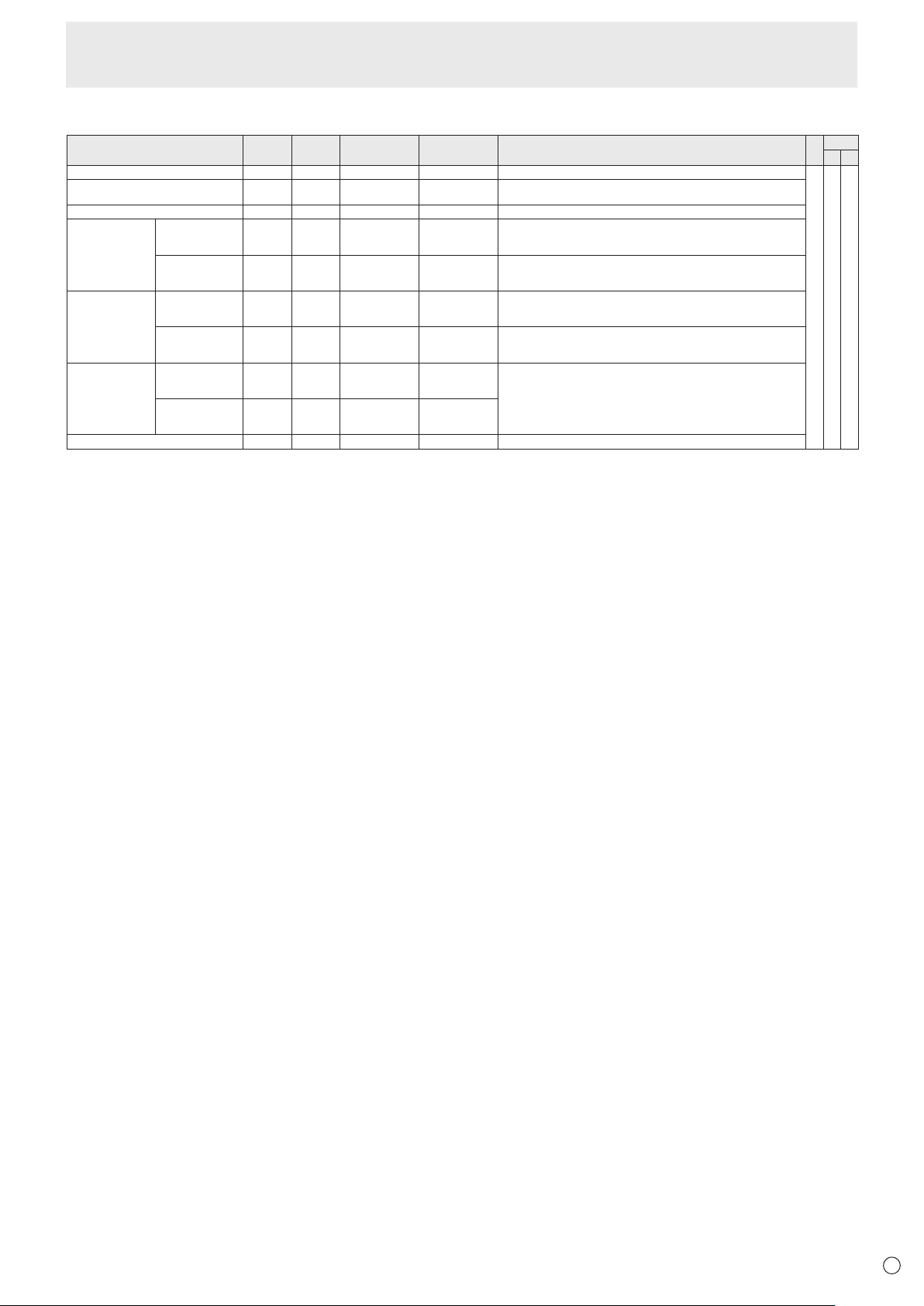
37
E
SCREEN menu
Function
Command Direction
Parameter Reply Control/Response contents *1
*2
(A) (B)
AUTO ASNC W 1 When the input mode is PC D-SUB, PC RGB.
-
○ ○
CLOCK CLCK WR 0-1200 0-1200 When the input mode is PC D-SUB, PC RGB.
Varies depending on the signal.
PHASE PHSE WR 0-63 0-63 When the input mode is PC D-SUB, PC RGB.
POSITIONING POSITION OF
THE LONGEST
DIRECTION
HPOS WR 0-100 0-100 0-800 on PC D-SUB, PC RGB.
Varies depending on the signal.
POSITION OF
THE SHORTEST
DIRECTION
VPOS WR 0-100 0-100 0-200 on PC D-SUB, PC RGB.
Varies depending on the signal.
SIZE SIZE OF THE
LONGEST
DIRECTION
HSIZ WR 0-100 0-100
SIZE OF THE
SHORTEST
DIRECTION
VSIZ WR 0-100 0-100
RESOLUTION
LONGEST
DIRECTION
RESOLUTION
HRES WR 300-1920 300-1920 When the input mode is PC D-SUB, PC RGB.
Only even numbers are valid for parameters.
Varies depending on the signal.
SHORTEST
DIRECTION
RESOLUTION
VRES WR 200-1200 200-1200
RESET ARST W 1
Controlling the Monitor with a PC (RS-232C)
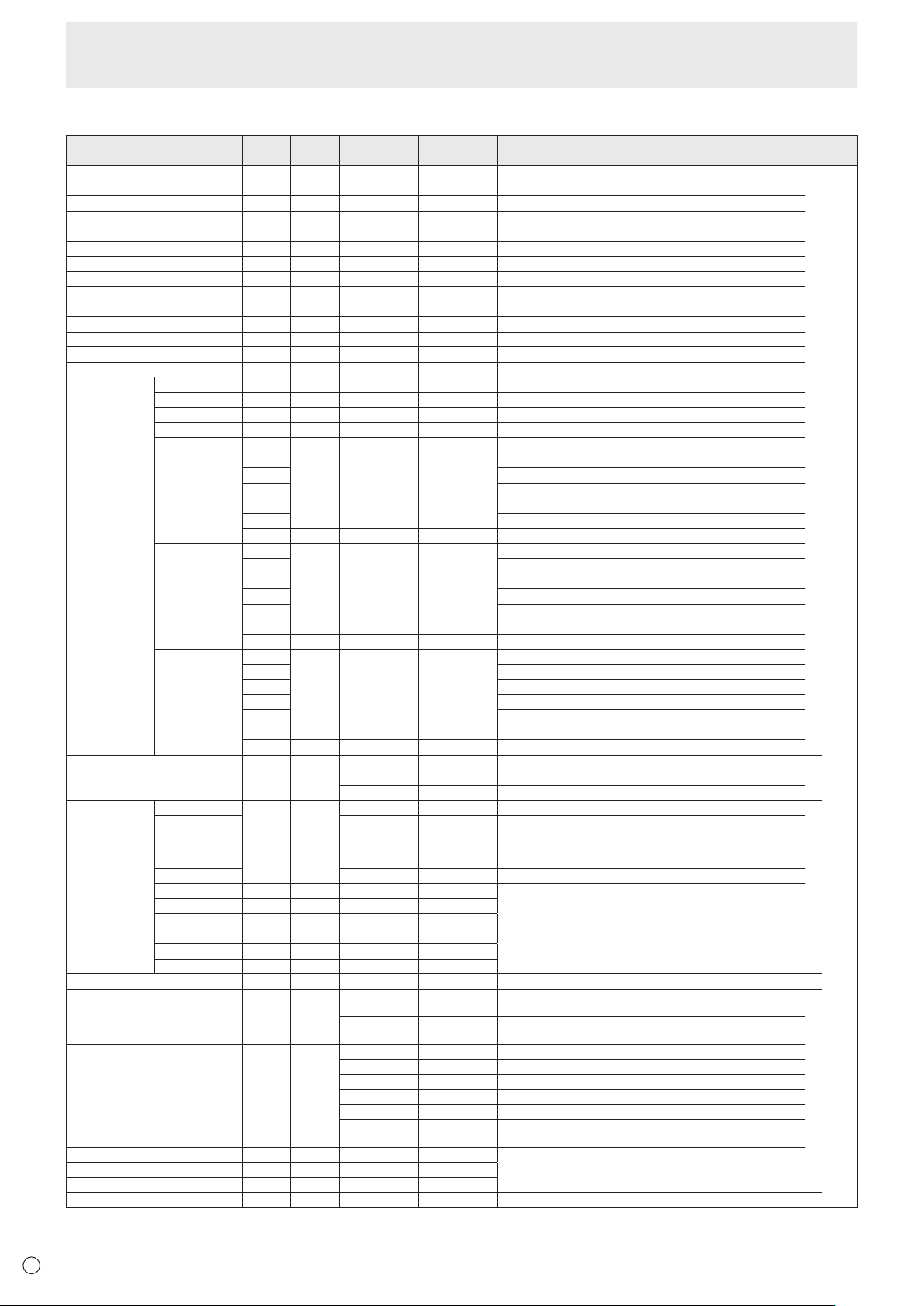
38
E
PICTURE menu
Function
Command Direction
Parameter Reply Control/Response contents *1
*2
(A) (B)
AUTO AGIN W 1 WhentheinputmodeisPCD-SUB,PCRGB. -
○
○
ANALOGGAIN ANGA WR 0-127 0-127 WhentheinputmodeisPCD-SUB,PCRGB.
○
ANALOGOFFSET ANOF WR 0-127 0-127 WhentheinputmodeisPCD-SUB,PCRGB.
CONTRAST CONT WR 0-60 0-60
BLACKLEVEL BLVL WR 0-60 0-60
TINT TINT WR 0-60 0-60
COLORS COLR WR 0-60 0-60
SHARPNESS SHRP WR 0-24 0-24
RGBINPUTRANGE(AVHDMI) AHDR WR 0-2 0-2 0:AUTO,1:FULL,2:LIMITED
RGBINPUTRANGE(PCHDMI) PHDR WR 0-2 0-2 0:AUTO,1:FULL,2:LIMITED
RGBINPUTRANGE(AVDVI) ADVR WR 1-2 1-2 1:FULL,2:LIMITED
RGBINPUTRANGE(PCDVI) PDVR WR 1-2 1-2 1:FULL,2:LIMITED
RGBINPUTRANGE(D-SUB) PDSR WR 1-2 1-2 1:FULL,2:LIMITED
RGBINPUTRANGE(PCBNC) PBRR WR 1-2 1-2 1:FULL,2:LIMITED
ADVANCED
(Whentheinput
modeisAV.)
FLESHTONE FLES WR 0-2 0-2 0:OFF,1:LOW,2:HIGH
○
○
3D-NR TDNR WR 0-2 0-2 0:OFF,1:LOW,2:HIGH
MPEG-NR MPNR WR 0-1 0-1 0:OFF,1:ON
3D-Y/C YCSP WR 0-1 0-1 0:OFF,1:ON(WhentheinputmodeisAVVIDEO)
C.M.S.-HUE CMHR WR -10-10 -10-10 R
CMHY Y
CMHG G
CMHC C
CMHB B
CMHM M
CRST W 1 Resets the hue.
C.M.S.-
SATURATION
CMSR WR -10-10 -10-10 R
CMSY Y
CMSG G
CMSC C
CMSB B
CMSM M
CRST W 2 Resets the saturation.
C.M.S.-VALUE CMVR WR -10-10 -10-10 R
CMVY Y
CMVG G
CMVC C
CMVB B
CMVM M
CRST W 3 Resets the brightness.
COLORMODE BMOD WR 0 0 STD
○
2 2 VIVID
3 3 sRGB(WhentheinputmodeisPC)
WHITEBALANCE THRU CTMP WR 0 0 WhentheinputmodeisPCDVI-D/PCHDMI.
○
PRESET 1-18 1-18 From1:approximately3,000Kto15:approximately10,000K
(500Ksteps)
16:approximately5,600K,17:approximately9,300K,
18:approximately3,200K
USER 99 99
R-CONTRAST CRTR WR 0-256 0-256 “ERR”whenCTMPisnotsetto99.
G-CONTRAST CRTG WR 0-256 0-256
B-CONTRAST CRTB WR 0-256 0-256
R-OFFSET OFSR WR -127-127 -127-127
G-OFFSET OFSG WR -127-127 -127-127
B-OFFSET OFSB WR -127-127 -127-127
COPYTOUSER CPTU W 0 Copiesapresetvaluetotheusersetting. -
GAMMA GAMM WR 0-2 0-2 0:1.8,1:2.2,2:2.4(duringPCinput)
0:LIGHT2,2:DARK(duringAVinput)
○
4-6 4-6 4: USER,5:2.0,6:STD(duringPCinput)
4:USER,5:LIGHT1,6:STD(duringAVinput)
DISPLAYCOLORPATTERN PTDF WR 0 0 No pattern display.
1 1 Whitesinglecolorpatterndisplay.
2 2 Red single color pattern display.
3 3 Greensinglecolorpatterndisplay.
4 4 Bluesinglecolorpatterndisplay.
99 99 Red/green/blue mixed color pattern display.
Seteachcolor'slevelwithRED,GREEN,BLUE.
RED PTDR WR 0-15 0-15 “ERR”whenPTDFisnotsetto99.
GREEN PTDG WR 0-15 0-15
BLUE PTDB WR 0-15 0-15
RESET ARST W 2
-
Controlling the Monitor with a PC (RS-232C)
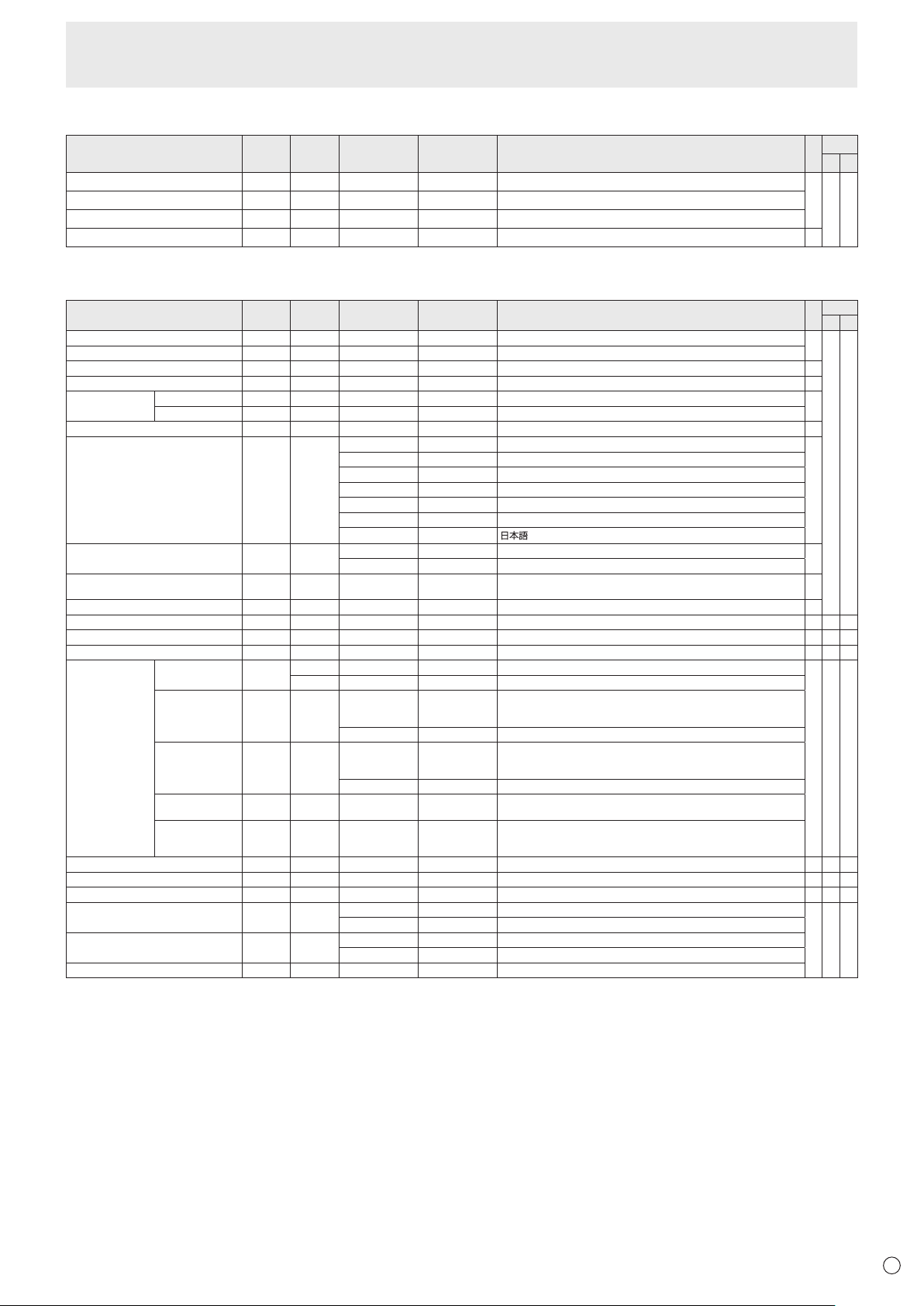
39
E
AUDIO menu
Function
Command Direction
Parameter Reply Control/Response contents *1
*2
(A) (B)
TREBLE AUTR WR -5-5 -5-5
○
○ ○
BASS AUBS WR -5-5 -5-5
BALANCE AUBL WR -10-10 -10-10
RESET ARST W 3
-
SETUP menu
Function
Command Direction
Parameter Reply Control/Response contents *1
*2
(A) (B)
OSD H-POSITION OSDH WR 0-100 0-100
○
○ ○
OSD V-POSITION OSDV WR 0-100 0-100
SCREEN MOTION SCSV WR 0-4 0-4 0: OFF, 1-4: PATTERN1-4
○
MOTION TIME 1 MTIM WR 0-20 0-20
○
MOTION TIME 2 PATTERN1 MINT WR 10-990 10-990 Per 10 seconds
○
PATTERN2-4 MINT WR 5-20 5-20 Per second
MONAURAL AUDIO MONO WR 0-1 0-1 0: OFF, 1: ON
○
LANGUAGE LANG WR 14 14 ENGLISH
○
1 1 DEUTSCH
2 2 FRANÇAIS
3 3 ITALIANO
4 4 ESPAÑOL
5 5 РУССКИЙ
6 6
POWER ON DELAY PWOD WR 0 0 OFF
○
1-60 1-60 ON
STANDBY MODE STBM WR 0-1 0-1 0: STANDARD, 1: LOW POWER
(“ERR" when SCHEDULE is effective or OFF is selected for LED.)
○
OFF IF NO OPERATION ATOF WR 0-1 0-1 0: OFF, 1: ON
○
HOT PLUG CONTROL (DVI) HPCT WR 0-1 0-1 0: OFF, 1: ON
○
-
○
HOT PLUG CONTROL (HDMI) HPCH WR 0-1 0-1 0: OFF, 1: ON
○ ○ ○
RS-232C/LAN SELECT CTLS WR 0-1 0-1 0 : RS-232C 1 : LAN
○
-
○
ID NUMBER ID NO. SETTING IDST W 0-255 Sets the monitor’s ID number. (“0” means “no ID number”.)
○ ○ ○
R 0-255 Returns the monitor’s ID number.
ID NO. SETTING
(ONCE)
IDSL W 1-255 Sets a monitor ID number.
This ID number is only effective for the command immediately after this
command.
0 Clears the ID number if one has been designated.
ID NO. SETTING
(SUBSEQUENT)
IDLK W 1-255 Sets a monitor ID number.
This ID number is effective for the next and all subsequent commands
after this command.
0 Clears the ID number if one has been designated.
ID CHECK IDCK W 0 ID : xxx
IDLK : yyy
Displays monitor’s own ID number and the selected ID number on the
screen.
ID DISPLAY IDDP W 0-2 0: OFF, 1: ON, 2: ON (turns OFF after 4 sec.)
(When the PN-ZB01 is attached, the IP address and MAC address are
both displayed.)
BAUD RATE BAUD WR 0-2 0-2 0: 9600bps, 1: 19200bps, 2: 38400bps
○ ○ ○
SPEAKER SELECT SPSL WR 0-1 0-1 0: Internal speaker, 1: External speaker
○
-
○
HDMI AUTO VIEW HDAW WR 0-1 0-1 0: OFF, 1: ON
○ ○ ○
SETTING COPY MODE CPMD WR 0 0 Copy to all monitors.
○ ○ ○
1-225 1-225 Copy to the monitor with the set ID Number.
SETTING COPY TARGET CPTG WR 0 0 Copies the PICTURE menu settings.
1 1 Copies all the settings.
LOGO SCREEN BTSC WR 0-1 0-1 0: OFF, 1: ON
Controlling the Monitor with a PC (RS-232C)
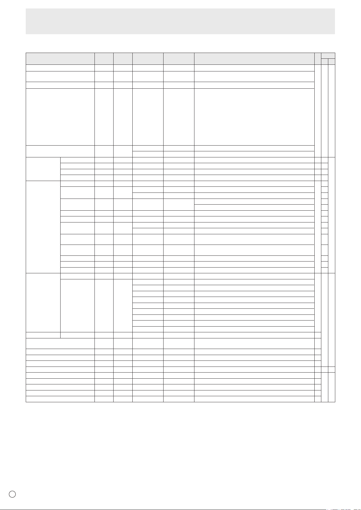
40
E
Controlling the Monitor with a PC (RS-232C)
OPTION menu
Function
Command Direction
Parameter Reply Control/Response contents *1
*2
(A) (B)
DATE/TIME SETTING DATE WR
AABBCCDDEE AABBCCDDEE
AA: Year, BB: Month, CC: Day, DD: Hour, EE: Minute
○ ○ ○
DATE DISPLAY FORMAT DTFT WR
0-2 0-2
0: YYYY/MM/DD, 1: MM/DD/YYYY, 2: DD/MM/YYYY
YYYY: Year, MM: Month, DD: Day
TIME DISPLAY FORMAT TMFT WR
0-1 0-1
0: 24-HOUR TIME, 1: 12-HOUR TIME
SCHEDULE SC01-
SC08
WR ABCDEFFGGH ABCDEFFGGH Schedule of a specied number
A: Schedule 0= Not effective, 1 = Effective
B: Power 0 = OFF, 1 = ON
C: Day of the week 1 0 = Only once, 1 = Every week, 2 = Every day
D: Day of the week 2 0 = Sunday, 1 = Monday through 6 = Saturday,
9 = Not exist
E: Day of the week 3 0 = Sunday, 1 = Monday through 6 = Saturday,
9 = Not exist
F: Hour 00-23
G: Minute 00-59
H: Input 0 = Not specied, 1 = PC DVI-D/AV DVI-D,
2 = PC D-SUB, 3 = PC RGB/AV COMPONENT,
4 = AV VIDEO, 5 = AV S-VIDEO,
6 = PC HDMI/AV HDMI
“ERR” when LOW POWER is selected for STANDBY MODE.
SCHEDULE BRIGHTNESS SB01-
SB08
WR 0-31 0-31 Screen brightness to change
99 99 Disable brightness setting
INPUT SELECT DVI DVSL WR 0-1 0-1 0: PC DVI-D, 1: AV DVI-D
○
-
○
BNC BNSL WR 0-1 0-1 0: PC RGB, 1: AV COMPONENT
○
-
D-SUB SLDS WR 0-2 0-2 0: PC D-SUB, 1: AV COMPONENT, 2: AV VIDEO
○ ○
HDMI HDSL WR 0-1 0-1 0: PC HDMI, 1: AV HDMI
○ ○
AUDIO SELECT PC DVI-D ASDP WR 1-3 1-3 1: AUDIO(STEREO MINI), 2: AUDIO1(RCA), 3: AUDIO2(RCA)
○
-
PC HDMI ASHP WR 0-1 0-1 0: HDMI, 1: AUDIO(STEREO MINI)
○
2-3 2-3 2: AUDIO1(RCA), 3: AUDIO2(RCA) -
PC D-SUB ASAP WR 1-3 1-3 1: AUDIO(STEREO MINI)
○
2: AUDIO1(RCA), 3: AUDIO2(RCA) -
PC RGB ASCP WR 1-3 1-3 1: AUDIO(STEREO MINI), 2: AUDIO1(RCA), 3: AUDIO2(RCA) -
AV DVI-D ASDA WR 1-3 1-3 1: AUDIO(STEREO MINI), 2: AUDIO1(RCA), 3: AUDIO2(RCA) -
AV HDMI ASHA WR 0-1 0-1 0: HDMI, 1: AUDIO(STEREO MINI)
○
2-3 2-3 2: AUDIO1(RCA), 3: AUDIO2(RCA) -
AV COMPONENT
(BNC)
ASCA WR 1-3 1-3 1: AUDIO(STEREO MINI), 2: AUDIO1(RCA), 3: AUDIO2(RCA)
-
AV COMPONENT
(D-SUB)
ASC2 WR 1-3 1-3 1: AUDIO(STEREO MINI), 2: AUDIO1(RCA), 3: AUDIO2(RCA)
○
AV S-VIDEO ASSA WR 1-3 1-3 1: AUDIO(STEREO MINI), 2: AUDIO1(RCA), 3: AUDIO2(RCA) -
AV VIDEO (BNC) ASVA WR 1-3 1-3 1: AUDIO(STEREO MINI), 2: AUDIO1(RCA), 3: AUDIO2(RCA) -
AV VIDEO (D-SUB)
ASV2 WR 1-3 1-3 1: AUDIO(STEREO MINI), 2: AUDIO1(RCA), 3: AUDIO2(RCA)
○
INPUT
RESOLUTION
(PC)
RESOLUTION CHECK
PXCK R - Returns current resolution in the form of hhh, vvv.
-
○ ○
PIXEL SETTING
(PC D-SUB, PC
RGB)
PXSL WR 1 1 768) 1360 x 768
2 2 768) 1280 x 768
3 3 768) 1024 x 768
5 5 480) 848 x 480
6 6 480) 640 x 480
7 7 1050) 1680 x 1050
8 8 1050) 1400 x 1050
9 9 768) AUTO
10 10 480) AUTO
INPUT RESOLUTION (AV)
RESOLUTION CHECK
RESO R - 480i, 480p, 1080i, 720p, 1080p, VGA , etc. -
ZOOM2 SPECIAL SETTING
(PC D-SUB, PC RGB)
Z2SP WR 0-1 0-1 0: OFF, 1: ON
○
SCAN MODE SCAN WR 0-2 0-2 0: MODE1, 1: MODE2, 2: MODE3 (When the input mode is AV)
○
POWER MANAGEMENT (PC) PMNG WR 0-1 0-1 0: OFF, 1: ON
○
POWER MANAGEMENT (AV) PMAV WR 0-1 0-1 0: OFF, 1: ON
○
COLOR SYSTEM CSYS WR 0-5 0-5 0: AUTO, 1: PAL, 2: PAL-60, 3: SECAM, 4: NTSC3.58, 5: NTSC4.43
○ ○ ○
AUDIO OUTPUT(RCA) AOUT WR 0-2 0-2 0: VARIABLE1, 1: FIXED, 2: VARIABLE2
○
○ ○
AUDIO LEVEL(STEREO MINI) AIVP WR 0-1 0-1 0: 1.0Vrms, 1: 0.5Vrms
○
SELF ADJUST AADJ WR 0-1 0-1 0: OFF, 1: ON
○
AUTO INPUT CHANGE AINC WR 0-1 0-1 0: OFF, 1: ON
○
TOUCH PANEL MODE GMDP WR 0-1 0-1 0: OFF, 1: ON (When the input mode is PC)
○
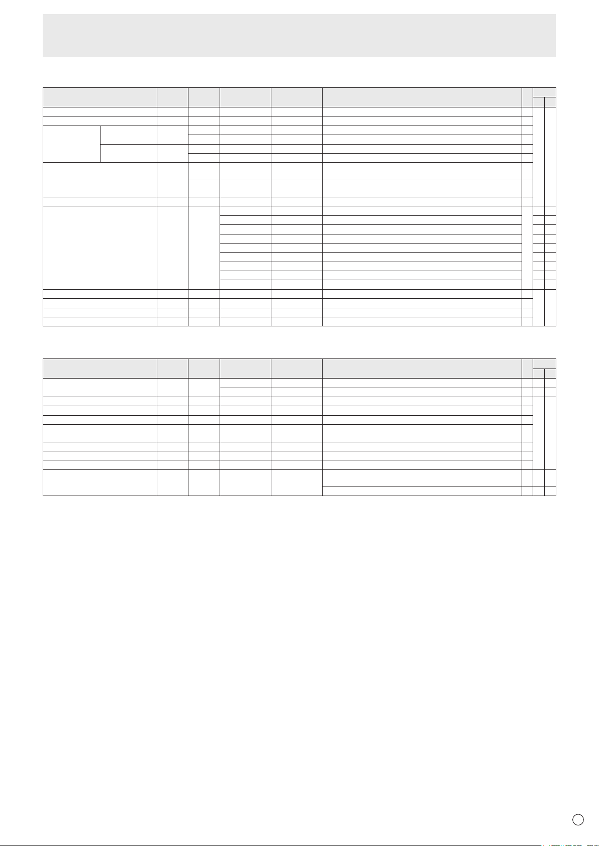
41
E
PIP/PbyP menu
Function
Command Direction
Parameter Reply Control/Response contents *1
*2
(A) (B)
PIPMODES MWIN WR 0-3 0-3 0:OFF,1:PIP,2:PbyP,3:PbyP2
○
○ ○
PIPSIZE MPSZ WR 1-64 1-64
○
PIP POS THELONGEST
DIRECTION
MHPS W 0-100
○
R 0-100
○
THESHORTEST
DIRECTION
MVPS W 0-100
○
R 0-100
○
PIPPOSLD+SDBATCH MPOS W 0-100,0-100 Specify the position in MPOSxxxyyy format.
(xxx: Longer side, yyy: Shorter side position)
○
R 0-100,0-100 Returns a response in (xxx,yyy) format.
(xxx: Longer side, yyy: Shorter side position)
○
PIPBLEND MWBL WR 0-15 0-15
○
PIPSOURCE MWIP WR 1 1 PCDVI-D
○
-
○
2 2 PCD-SUB
○ ○
3 3 AVCOMPONENT(BNC)/AVCOMPONENT(D-SUB)
○ ○
4 4 AVVIDEO(BNC)/AVVIDEO(D-SUB)
○ ○
6 6 PCRGB -
○
7 7 AVDVI-D -
○
8 8 AVS-VIDEO -
○
9 9 AVHDMI
○ ○
10 10 PCHDMI
○ ○
SOUNDCHANGE MWAD WR 1-2 1-2 1:MAIN,2:SUB
○
○ ○
MAIN POS (Main screen) MWPP WR 0-1 0-1 0:POS1,1:POS2
○
PbyP2 POS (Sub screen) MW2P WR 0-2 0-2 0:POS1,1:POS2,2:POS3
○
AUTOOFF MOFF WR 0-1 0-1 0:MANUAL,1:AUTO
○
Initialization/Functional Restriction Setting (FUNCTION) menu
Function
Command Direction
Parameter Reply Control/Response contents *1
*2
(A) (B)
ALLRESET RSET W 0 0:ALLRESET -
○
-
0-1 0:ALLRESET1,1:ALLRESET2 - -
○
ADJUSTMENTLOCK ALCK WR 0-2 0-2 0:OFF,1:ON1,2:ON2
○
○ ○
ADJUSTMENTLOCKTARGET ALTG WR 0-2 0-2 0:REMOTECONTROL,1:MONITORBUTTONS,2:BOTH
○
OSDDISPLAY LOSD WR 0-2 0-2 0:ON1,1:OFF,2:ON2
○
LED OFLD WR 0-1 0-1 0:ON,1:OFF
“ERR”whenLOWPOWERisselectedforSTANDBYMODE.
○
TEMPERATUREALERT TALT WR 0-2 0-2 0:OFF,1:OSD&LED,2:LED
○
STATUSALERT SALT WR 0-2 0-2 0:OFF,1:OSD&LED,2:LED
○
POWERBUTTON PBTN WR 0-1 0-1 0:MONITOR,1:CONTROLLER
○
CONTROLLERINPUT PCIP WR 0-2 0-2 0:D-SUB,1:HDMI(“ERR”whenMONITORisselectedforPOWER
BUTTON.)
○ ○ ○
2:DVI-D(“ERR”whenMONITORisselectedforPOWERBUTTON.)
○
-
○
Controlling the Monitor with a PC (RS-232C)
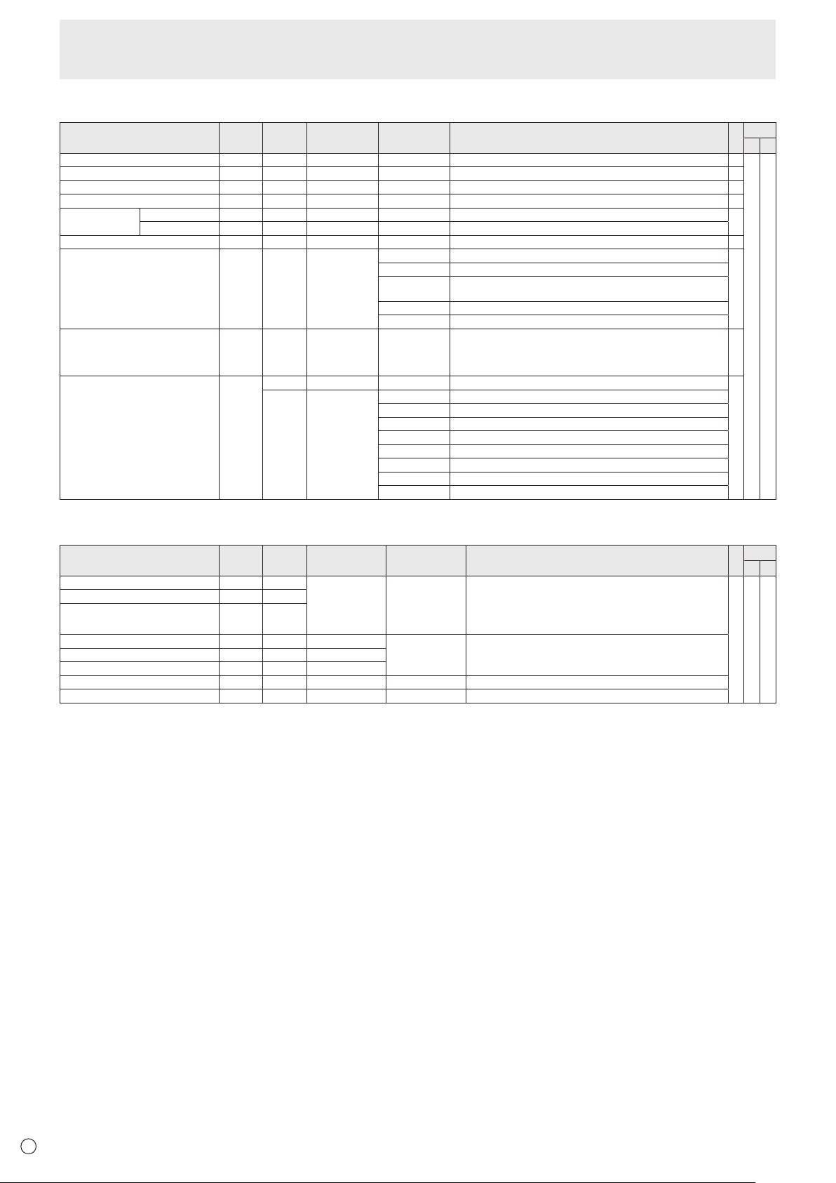
42
E
Others
Function
Command Direction
Parameter Reply Control/Response contents *1
*2
(A) (B)
SCREEN SIZE (PC) WIDE WR 1-5 1-5 1: WIDE, 2: NORMAL, 3: Dot by Dot, 4: ZOOM1, 5: ZOOM2
○
○ ○
SCREEN SIZE (AV) WIDE WR 1-5 1-5 1: WIDE, 2: ZOOM1, 3: ZOOM2, 4: NORMAL, 5: Dot by Dot
○
VOLUME VOLM WR 0-31 0-31
○
MUTE MUTE WR 0-1 0-1 0: OFF, 1: ON -
INFORMATION MODEL INF1 R Value
●
SERIAL NO SRNO R Value
BRIGHT VLMP WR 0-31 0-31
○
TEMPERATURE SENSOR DSTA R 0 Internal temperature normal
●
1 Internal temperature abnormal (Standby mode)
2 Internal temperature abnormal (Temperature is normal now, but it was
abnormal during operation.)
3 Internal temperature abnormal (Brightness of the backlight decreases.)
4 Temperature sensor abnormal
TEMPERATURE ACqUISITION ERRT R Value Temperature at temperature sensors 1 through 3 are returned in the
following forms:
[Sensor 1], [Sensor 2], [Sensor 3]
Indicates a temperature sensor abnormality when “126” is returned.
○
CAUSE OF LAST STANDBY MODE STCA W 0 Initialization
●
R 0 No detectable error has occurred
1 Standby mode by POWER button
2 Main power off by the main power switch
3 Standby mode by RS-232C or LAN
4 Input signal waiting mode by No Signal
6 Standby mode by abnormal temperature
8 Standby mode by SCHEDULE setting
20 Standby mode by OFF IF NO OPERATION setting
Commands for setting of the GAMMA user data
Function
Command Direction
Parameter Reply Control/Response contents *1
*2
(A) (B)
RED GAMMA DATA TRANSFER UGRW W aaxxxx
···
xxxxcc
(xxxx: 32 pieces)
aa: 01-16
xxxx: 0000-1023
cc: 00-FF
aa: Block number
xxxx: 32 pieces of user data
cc: Checksum (ASCII data) of the block number and user data
○ ○ ○
GREEN GAMMA DATA TRANSFER UGGW W
BLUE GAMMA DATA TRANSFER UGBW W
RED GAMMA DATA READ UGRR W 1-16 xxxx
···
xxxx
(xxxx: 32 pieces)
xxxx: 0000-1023
xxxx: User data of 32 pieces
GREEN GAMMA DATA READ UGGR W 1-16
BLUE GAMMA DATA READ UGBR W 1-16
USER DATA INITIALIZE UGRS W 0 Initialize the user data.
USER DATA SAVE UGSV W 0 Save the user data in the monitor.
Controlling the Monitor with a PC (RS-232C)
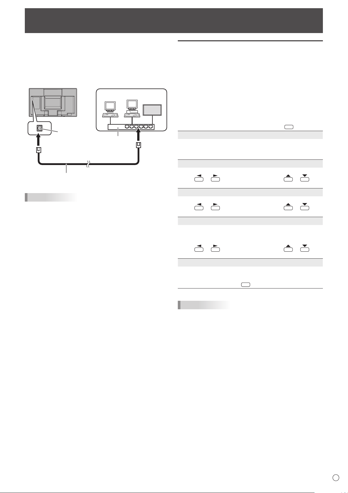
43
E
WhenthePN-ZB01(optional)isattached,yourmonitorcan
beconnectedtoaLANallowingyoutocontrolitfromaPCon
the LAN.
Youcanalsocongurethemonitortosende-mailnotication
when it has a problem.
TheconnectionrequiresacommerciallyavailableLANcable
(UTPcable,Category5,straightthrough).
Hub
LAN terminal
LAN cable (commercially available, straight)
Network (LAN)
TIPS
• YoumustassignanIPaddresstothemonitorbyfollowing
the procedures in “Settings to connect to a LAN”. (See the
description on the right.)
• YourPCmustbeinstalledwithInternetExplorer(version7.0
or later).
• TocontrolthemonitorviaLAN,setRS-232C/LANSELECT
to LAN. (See page 26.)
• YoucannotuseRS-232CandLANcontrolsimultaneously.
Initializing personal information
• WhenthePN-ZB01(optional)isattached,personal
informationsuchase-mailaddressescanberegisteredin
themonitor.Beforetransferringordisposingofthemonitor,
initializeallsettingsbyselectingALLRESET1.(See
page31.)NotethatALLRESET2willnotinitializee-mail
addresses and other settings.
Controlling the Monitor with a PC (LAN)
Settings to connect to a LAN
Set the monitor’s IP address and subnet mask to match the
settings of your LAN.
ThesesettingscanbemadeoneitherthemonitororaPC
connected to the monitor.
ThesettingsdependonthecongurationofyourLAN.Ask
your LAN administrator for details.
■ To set on the monitor
SetRS-232C/LANSELECTontheSETUPmenutoLAN,and
thensettheLANSETUPoptions.(Seepage26.)
Aftersettingeachitem,selectSETandpress
MENU
.
DHCP CLIENT
IfyourLANhasaDHCPserverandyouwishtoobtainan
address automatically, change this setting to ON.
Tosettheaddressmanually,setthistoOFF.
IP ADDRESS
IftheDHCPCLIENTissettoOFF,specifyanIPaddress.
Press
or to select items, and press or to
change the values.
SUBNET MASK
IftheDHCPCLIENTissettoOFF,specifythesubnetmask.
Press
or to select items, and press or to
change the values.
DEFAULT GATEWAY
IftheDHCPCLIENTissettoOFF,specifythedefault
gateway.
Ifyouarenotusingagateway,specify“0.0.0.0”.
Press
or to select items, and press or to
change the values.
RESET
Resets the values of the LAN settings to the factory preset
values.
Select ON and then press
MENU
.
TIPS
• WhentheIPaddressissetmanually,theIPaddressesof
themonitorconnectedtotheRS-232Coutputterminal and
the daisy chain of connected monitors that follows can be
assigned automatically. (See page 26.)
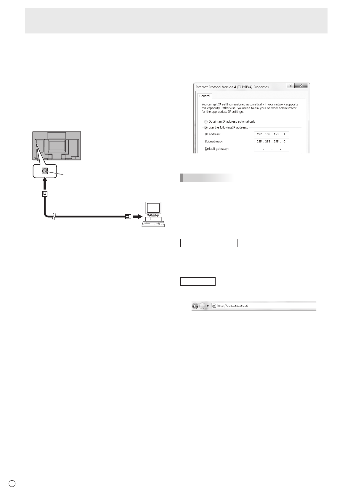
44
E
■ To set from a PC
WhenthemonitorisconnectedtoaPC,LANsettingscanbe
conguredviaPC.
Set up process
(1)ConnectyourmonitortoaPC
(2)SpecifythePC’sIPaddress
(3)Congurethemonitor’sLANsettings
(1) Connecting your monitor to a PC
ConnectacommerciallyavailablecrossoverLANcable
(UPTcable,Category5)totheLANportonthePCandthis
monitor.
LAN cable
(commercially available, crossover)
To LAN terminal
PC
LAN terminal
(2) Specifying the PC’s IP address
Tocongurethemonitor’sLANsettings,youmusttemporarily
changethesettingsonthePC.
ThisexplanationisbasedonWindows7.
1. LogontothePCwithanadministratoraccount.
2. Click[Start],andthenclick“ControlPanel”.
3. Click“Viewnetworkstatusandtasks”in“Networkand
Internet”.
In“ClassicView”,click“NetworkandSharingCenter”.
4. Click“LocalAreaConnection”andthen“Properties”.
5. Click“InternetProtocolVersion4(TCP/IPv4)”andthen
“Properties”.
6. Make a note of the current IP address, subnet mask, and
default gateway settings.
Make sure you write this information now as you will
be changing the IP address, subnet mask, and default
gateway settings back to these settings afterwards.
7. Temporarily change the IP address and subnet mask.
To access the monitor as it is shipped from the factory, set
as follows.
• IPAddress:192.168.150.1
• SubnetMask:255.255.255.0
• DefaultGateway:(leaveblank)
8. Click[OK]andthenrebootthePC.
TIPS
• Thismonitorisfactorypresetasshownbelow.
(WhenDHCPCLIENTissettoOFF)
IPAddress :192.168.150.2
SubnetMask :255.255.255.0
DefaultGateway :0.0.0.0
(3) Conguring the monitor’s LAN settings
AccessthemonitorusingInternetExplorer.
Controllingthemonitor
1. TurnthepowerONtothemonitor.
2. SetRS-232C/LANSELECTontheSETUPmenutoLAN.
3.SetDHCPCLIENTtoOFFinLANSETUPontheSETUP
menu.
PCoperation
4. LaunchInternetExplorer,inthe“Address”boxtype
“http://192.168.150.2/”andpresstheEnterkey.
You will be prompted to enter a user name and password.
5. Leavetheusernameandpasswordboxesblankandclick
[OK].
Controlling the Monitor with a PC (LAN)
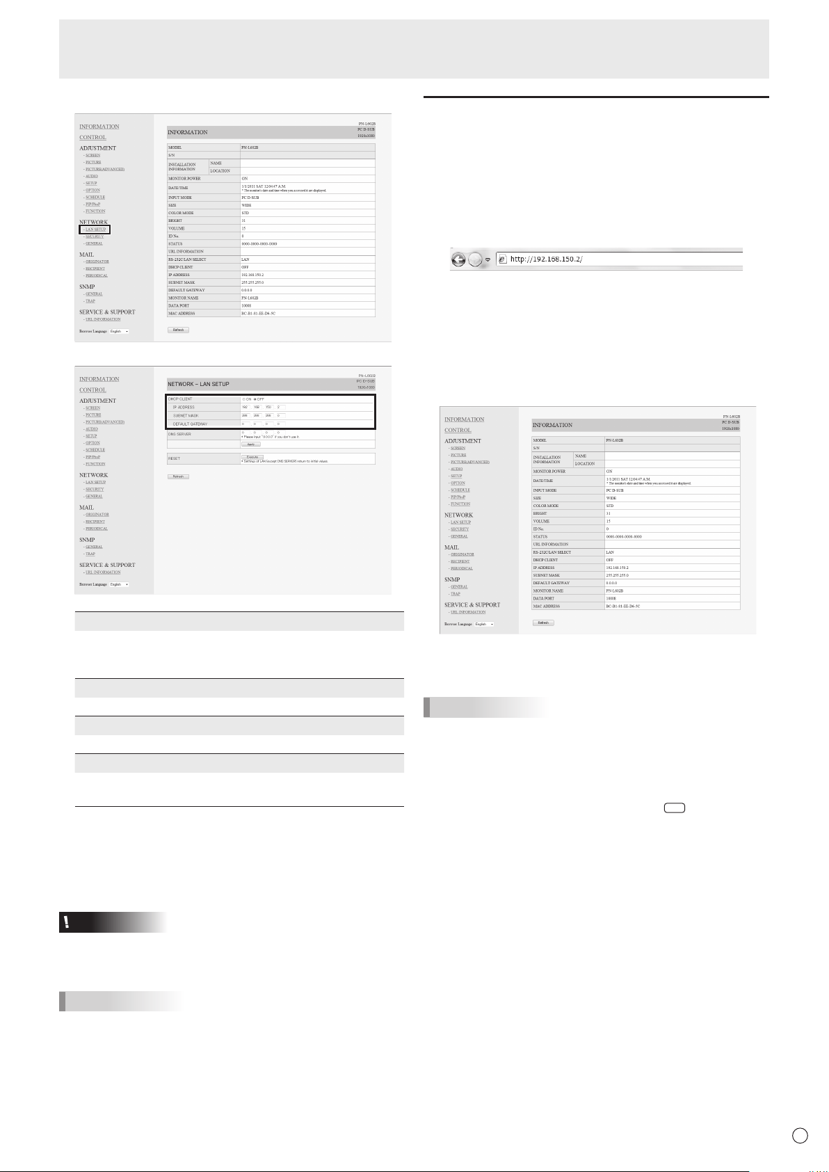
45
E
6. Clickon“LANSETUP”underNETWORK.
7. Specifythe“DHCPCLIENT”,“IPADDRESS”,etc.
DHCP CLIENT
IfyourLANhasaDHCPserverandyouwishtoobtainan
address automatically, change this setting to “ON”.
Tosettheaddressmanually,setthisto“OFF”.
IP ADDRESS
IftheDHCPCLIENTissetto“OFF”,specifyanIPaddress.
SUBNET MASK
IftheDHCPCLIENTissetto“OFF”,specifythesubnetmask.
DEFAULT GATEWAY
IftheDHCPCLIENTissetto“OFF”,specifythedefaultgateway.
Ifyouarenotusingadefaultgateway,specify“0.0.0.0”.
8. Whenthesettingischanged,click[Apply].
9. Checkthemessageandclick[OK].
10
.ExitInternetExplorer.
11.
RestorethePC’sIPaddressjottedinStep6,“(2)
SpecifyingthePC’sIPaddress”.
12.
ConnectthemonitorandthePCtotheLAN.
Caution
• Wait10secondsafterclicking[OK]beforeproceeding.
• Whenoperatingusingtheremotecontrolunitorsimilar,
click[Refresh].
TIPS
• WhentheIPaddressissetmanually,theIPaddressesof
themonitorconnectedtotheRS-232Coutputterminaland
the daisy chain of connected monitors that follows can be
assigned automatically. (See page 26.)
Controlling with a PC
■ Basic operation
YouuseInternetExploreronaPContheLANtocontrolthe
monitor.
1. LaunchInternetExploreronthePC.
2.
In the “Address” box, type “http://” followed by your monitor’s
IPaddressfollowedby“/”,thenpresstheEnterkey.
YoucanconrmtheIPaddresswiththeDISPLAYfunction.
Whenpromptedtoenterausernameandpassword,type
theusernameandpasswordthatyouspeciedinthe
securitysettings(seepage47),andclick[OK].
If you did not make any security settings, leave the spaces
blankandclickon[OK].
3. You can check, control, and change the monitor’s status
and settings by clicking the menu items on the left side of
the screen.
• Ifyouseean[Apply]buttonnexttoasetting,clickitafter
you change that setting.
TIPS
• Seepages46to50fordetailsoneachsetting.
• Ifyouclick[Refresh]beforethescreennishesupdating
thecurrentdisplay,the“ServerBusyError”willappear.
Waitforamomentbeforeoperatingyourmonitoragain.
• Youcannotoperatethemonitorwhileitiswarmingup.
• If“DHCPCLIENT”issetto“ON”,press
DISPLA
Y
on the
remote control unit two times and then check the monitor’s
IP address.
Controlling the Monitor with a PC (LAN)
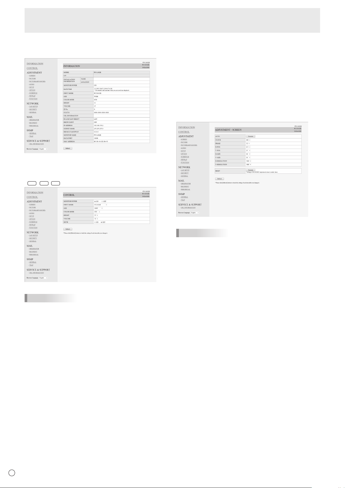
46
E
■ INFORMATION
Information about this monitor appears.
■ CONTROL
You can control the operations corresponding to the buttons
(
POWER
INPUT
SIZE
)ontheremotecontrolunit.(Seepage21.)
TIPS
• Instandbymode,PowerONistheoperationavailable.
■ ADJUSTMENT
Youcanadjustthesesettingswhicharealsoavailableonthe
monitor’s menu.
• SCREEN(Seepage24.)
• PICTURE(Seepage24.)
• PICTURE(ADVANCED)(Seepage30.)
• AUDIO(Seepage25.)
• SETUP(Seepage25.)
• OPTION(Seepage26.)
• SCHEDULE(Seepage29.)
• PIP/PbyP(Seepage27.)
• FUNCTION(Seepage31.)
TIPS
• AfterchangingDISPLAYCOLORPATTERNtoOFF,click
[Refresh]tocorrectlyretrievethestatusofthemonitor.
Controlling the Monitor with a PC (LAN)
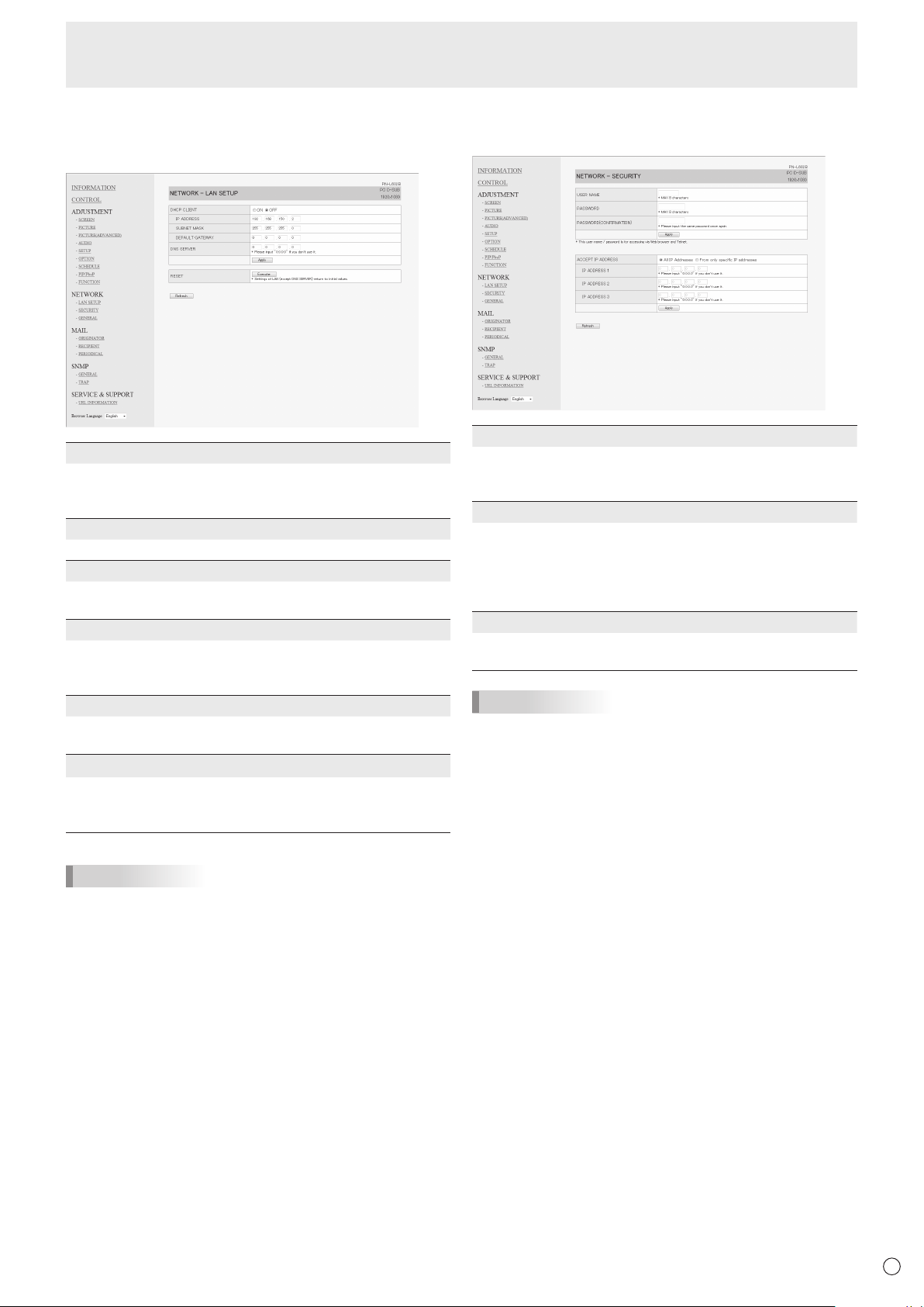
47
E
■ NETWORK (LAN SETUP)
This screen allows you to set the settings necessary when the
monitor is connected to a LAN.
DHCP CLIENT
IfyourLANhasaDHCPserverandyouwishtoobtainan
address automatically, change this setting to “ON”.
Tosettheaddressmanually,setthisto“OFF”.
IP ADDRESS
IftheDHCPCLIENTissetto“OFF”,specifyanIPaddress.
SUBNET MASK
IftheDHCPCLIENTissetto“OFF”,specifythesubnet
mask.
DEFAULT GATEWAY
IftheDHCPCLIENTissetto“OFF”,specifythedefault
gateway.
Ifyouarenotusingadefaultgateway,specify“0.0.0.0”.
DNS SERVER
SpecifytheDNSserveraddress.
IfyouarenotusingaDNSserver,specify“0.0.0.0”.
RESET
Clicking[Execute]returnsalloftheLANSETUPsettings
tothefactory-presetvaluesexceptfortheDNSSERVER
setting.
TIPS
• WhentheIPaddressissetmanually,theIPaddressesof
themonitorconnectedtotheRS-232Coutputterminal and
the daisy chain of connected monitors that follows can be
assigned automatically. (See page 26.)
■ NETWORK (SECURITY)
Thisscreenallowsyoutospecifythesecurity-relatedsettings.
USER NAME / PASSWORD
Sets up a user name and password to restrict access to this
monitor.
Afterenteringausernameandpassword,click[Apply].
ACCEPT IP ADDRESS
You can limit access to this monitor by registering IP
addressesofPCsthatshouldhaveaccess.
Tolimitaccess,specifytheoption“FromonlyspecicIP
addresses”.Otherwise,toallowaccessfromanyPC,specify
“All IP Addresses”.
IP ADDRESS 1 to 3
If“ACCEPTIPADDRESS”issetto“FromonlyspecicIP
addresses”, enter the IP addresses that you want to allow.
TIPS
• TheUSERNAMEandPASSWORDcanbeupto8
alphanumeric characters or symbols.
• Tocanceltheusernameand/orpasswordafterithasbeen
set,maketheboxemptyandclick[Apply].
Controlling the Monitor with a PC (LAN)
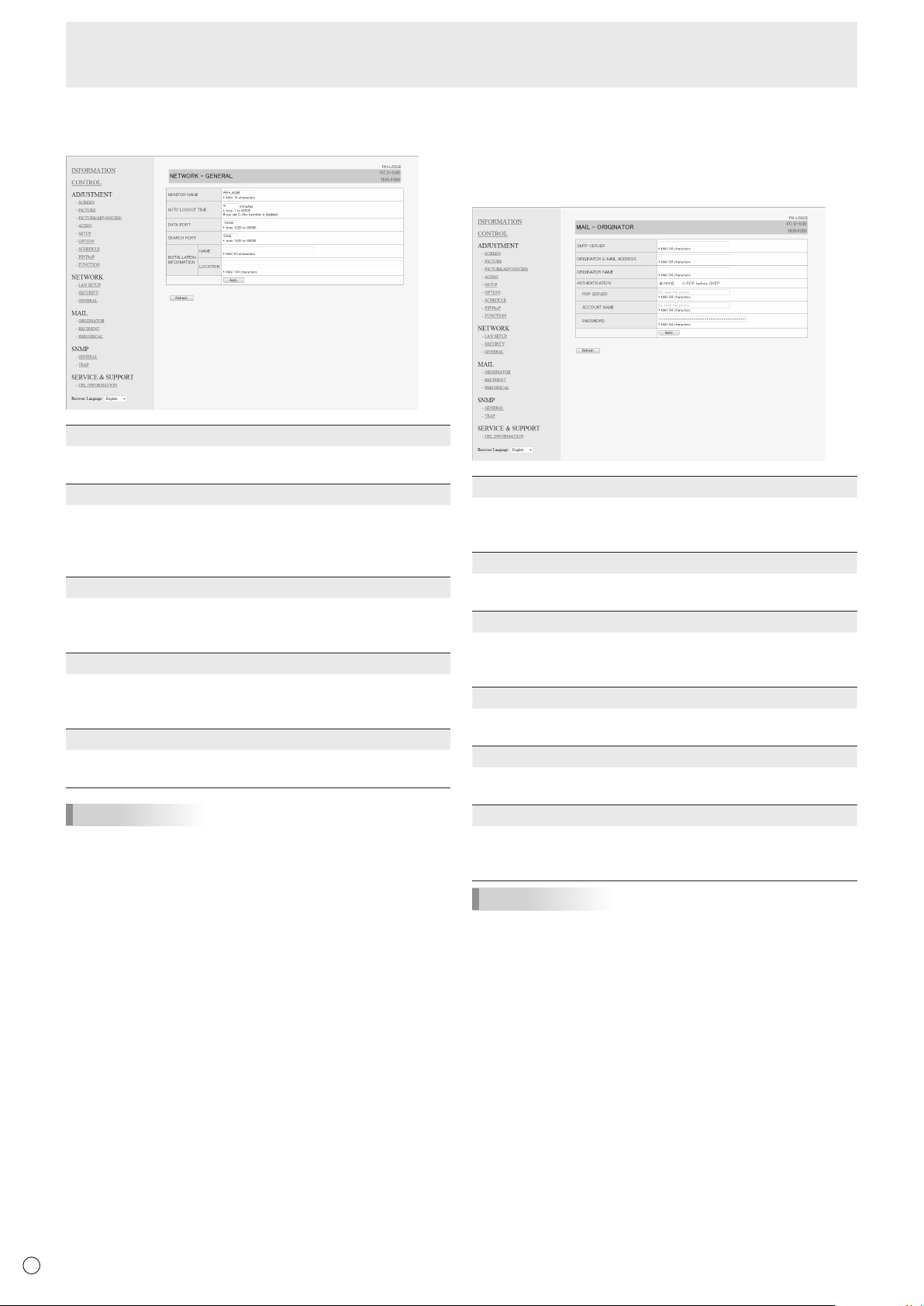
48
E
■ NETWORK (GENERAL)
This screen allows you to specify the general LAN settings.
MONITOR NAME
Specify a name for this monitor as it should appear on the
InternetExplorerscreen.
AUTO LOGOUT TIME
Specify the time (in minutes) to elapse before automatically
disconnecting this monitor from the network.
Specifyinminutesfrom1to65535.Avalueof‘0’willdisable
this function.
DATA PORT
SpecifytheTCPportnumbertouseforexchangingdatawith
the monitor.
Specifyavaluefrom1025to65535.
SEARCH PORT
Specify the port number to use when searching for this
monitor.
Specifyavaluefrom1025to65535.
INSTALLATION INFORMATION (NAME/LOCATION)
Specify the information to display for this monitor in the
InternetExplorerwindow.
TIPS
• TheMONITORNAMEcanbeupto16alphanumeric
characters or symbols.
• Enterupto50charactersintheNAMEeldinthe
INSTALLATIONINFORMATION.
• Enterupto100charactersintheLOCATIONeldinthe
INSTALLATIONINFORMATION.
■ MAIL (ORIGINATOR)
Thisscreenallowsyoutocongurethee-mailsentperiodically
or when the monitor has an error.
ThesettingsdependonthecongurationofyourLAN.Ask
your LAN administrator for details.
SMTP SERVER
SpecifytheSMTPserveraddressforsendinge-mail.
* Whenusingadomainname,makesuretospecifythe
DNSSERVER as well. (See page 47.)
ORIGINATOR E-MAIL ADDRESS
Specifythee-mailaddressforthismonitor.
Thisaddressbecomesthee-mailaddressoftheoriginator.
ORIGINATOR NAME
Specify the name for the originator.
Thisnameappearsinthe“OriginatorName”eldofthe
e-mail.
AUTHENTICATION
Specify the authentication method to use when sending
e-mail.
POP SERVER
Ifthe“AUTHENTICATION”methodis“POPbeforeSMTP”,
specify the POP server address.
ACCOUNT NAME / PASSWORD
Ifthe“AUTHENTICATION”methodis“POPbeforeSMTP”,
specify the account name and password to connect to the
POP server.
TIPS
• Youcanenterupto64alphanumericcharactersorsymbols
fortheORIGINATORE-MAILADDRESS,ORIGINATOR
NAME,ACCOUNTNAME,andPASSWORD.
• TheSMTPSERVERandPOPSERVERcanbeupto64
characters.
Thefollowingcharacterscanbeused:a-z,A-Z,0-9,-,.
Controlling the Monitor with a PC (LAN)
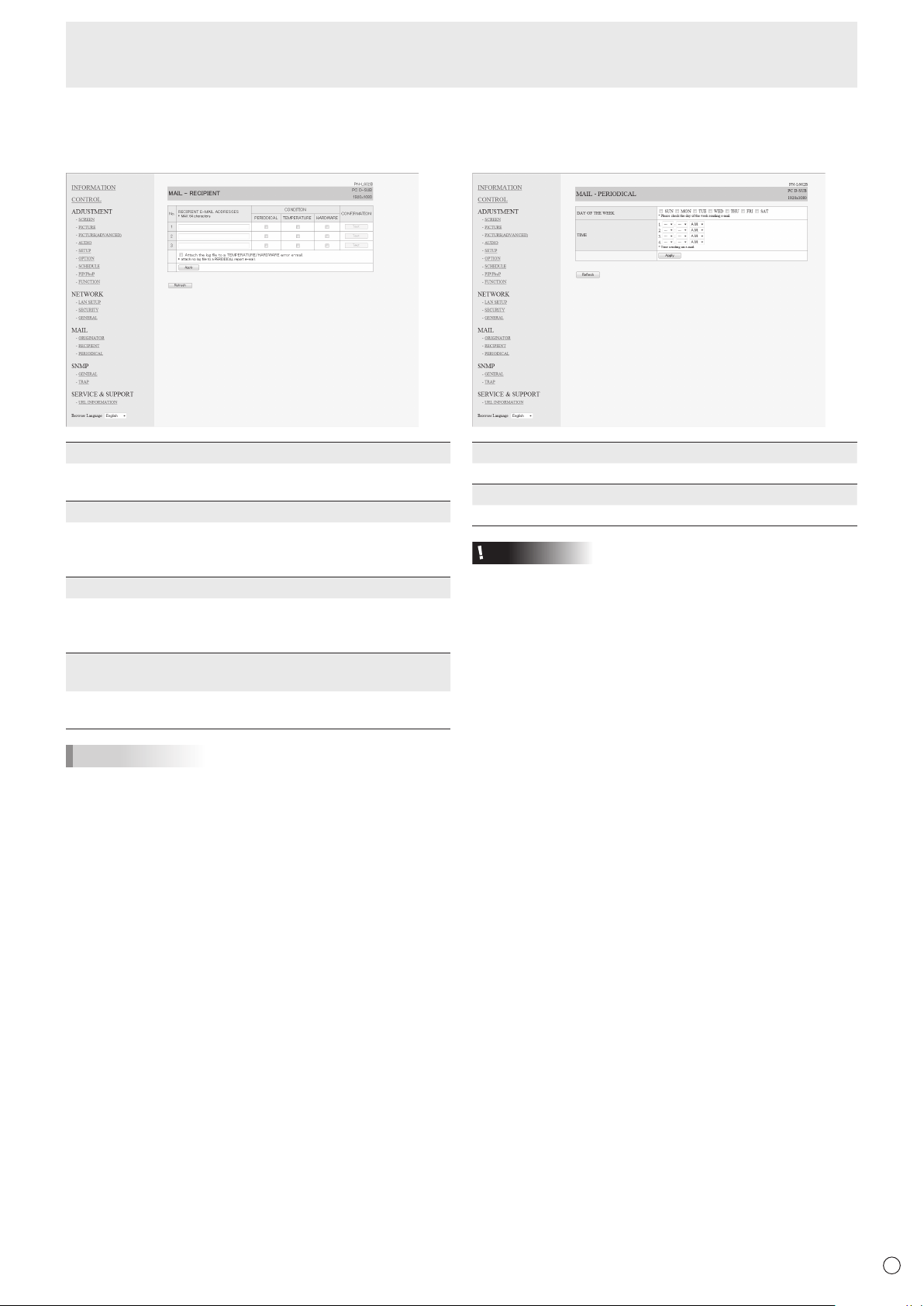
49
E
■ MAIL (RECIPIENT)
Thisscreenallowsyoutospecifytherecipientsofthee-mail
sent periodically or when the monitor has an error.
RECIPIENT E-MAIL ADDRESSES
Specifythee-mailaddressestosenderrornoticatione-mail
to.
CONDITION
Specify the conditions to send mails.
WhenyoucheckPERIODICAL,specifythedateandtimeto
sendthemailsinthePERIODICALsetting.
CONFIRMATION
Sendsteste-mail.
Thisallowsyoutoconrmthatthee-mailsettingsare
conguredproperly.
Attach the log le to a TEMPERATURE/HARDWARE error
e-mail.
Whenthisoptionischecked,alogisaddedtothemailwhich
notiesatemperatureorstatuserror.
TIPS
• TheRECIPIENTE-MAILADDRESSEScanbeupto64
alphanumeric characters or symbols.
Controlling the Monitor with a PC (LAN)
■ MAIL (PERIODICAL)
WhenPERIODICALforCONDITIONofMAIL(RECIPIENT)is
checked, set the date and time to send the mail.
DAY OF THE WEEK
Specify the day of the week to send the periodical mails.
TIME
Specify the time of the day to send the periodical mails.
Caution
• Donotturnoffthemainpowerwhenyousettosendthe
periodical mails.
• Specifythecorrectdateandtime.(Seepage26.)
If the date and time settings are incorrect, the periodical
mail is not sent properly.
• Regularlyconrmthatthespecieddateandtimeis
correct.
• WhenLOWPOWERisselectedforSTANDBYMODE,
periodical mails will not be sent in standby mode.
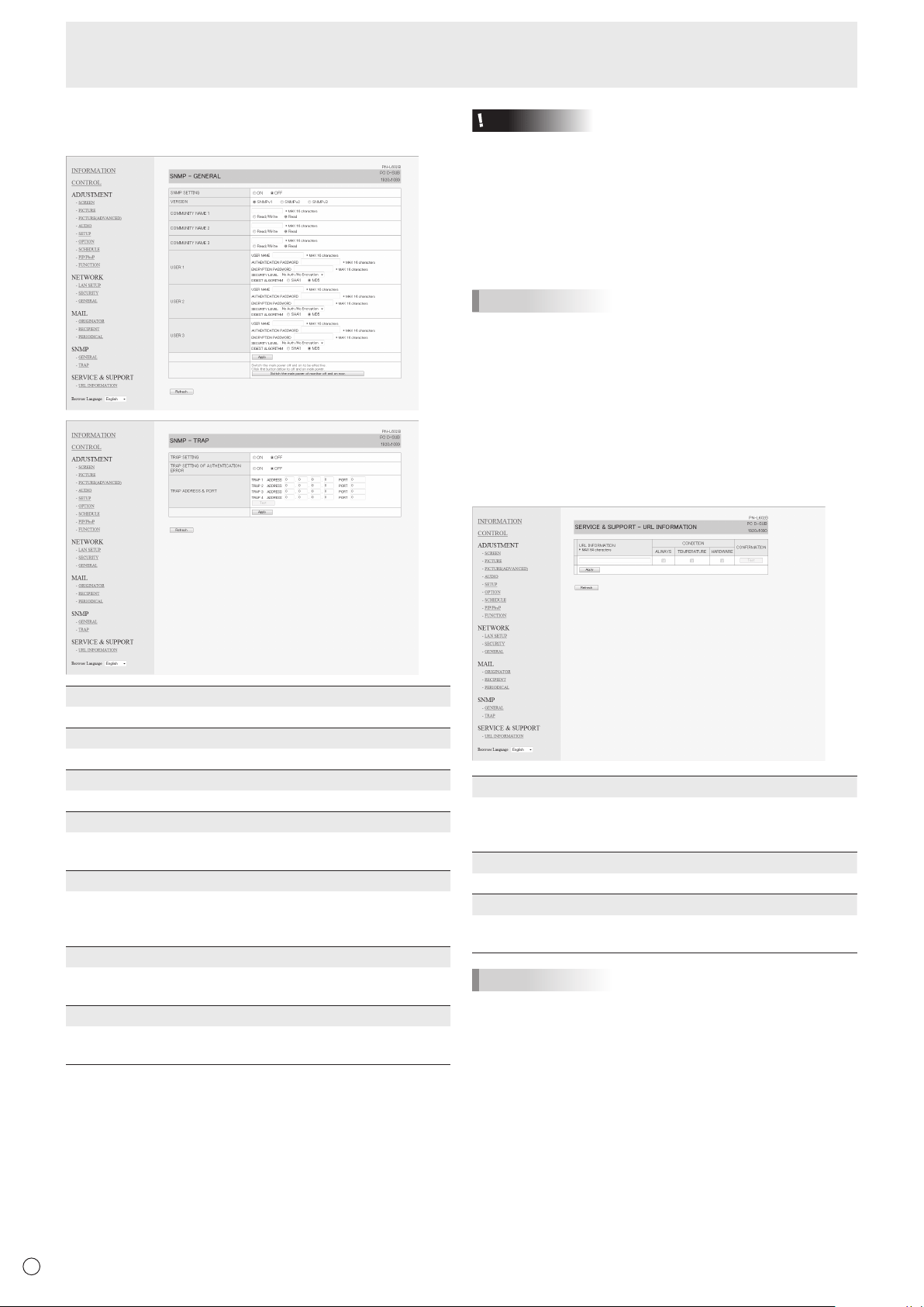
50
E
Controlling the Monitor with a PC (LAN)
■ SNMP
YoucanconguresettingsrelatedtoSNMP.
SNMP SETTING
Set whether to enable or disable SNMP.
VERSION
Set the version of the SNMP to be supported.
COMMUNITY NAME 1 to 3
Setthenameofthecommunityrequiredfortheaccess.
USER 1 to 3
Set the user name, password, authentication method and
otheroptionsrequiredforaccess.
TRAP SETTING
Set whether to enable or disable the trap function.
Whenthisfunctionisenabled,atrapwillbesentwhenthe
monitor is turned on.
TRAP SETTING OF AUTHENTICATION ERROR
Setwhetherthetrapfunctionsendsanoticationwhen
authentication fails.
TRAP ADDRESS & PORT
Set the destination address and port number of the
noticationsentbythetrapfunction.
Caution
• AfteryousetSNMP,click[Switchthemainpowerof
monitoroffandonnow.]orturnoffthemonitorandthen
turnitonagainwiththemainpowerswitch.Whenthe
monitorrestarts,waitabout30secondsandthenstartthe
next operation.
• IftheIPaddressischangedwhiletheSNMPfunctionis
operational, turn off the monitor and then turn it on again
with the main power switch.
TIPS
• DependingontheSNMPsettings,ashortdelaymayoccur
before the SNMP is usable. (About 2 minutes)
• Upto16alphanumericlettersandsymbolscanbeusedfor
the community name, user name and password.
■ SERVICE & SUPPORT
(URL INFORMATION)
YoucandisplayaspecicURLintheURLINFORMATION
eldontheINFORMATIONscreenwhenanerroroccursin
the monitor. (See page 46.)
URL INFORMATION
EntertheURLtodisplayontheINFORMATIONscreenwhen
an error occurs on the monitor.
Up to 64 alphanumeric characters or symbols can be used.
CONDITION
Specify the condition to display the URL.
CONFIRMATION
ThehomepageofthespeciedURLisdisplayed.
You can check whether the URL you entered is correct.
TIPS
• Itisalsopossibletospecifythemessagetext,suchasthe
name of a contact or a telephone number, to be displayed
instead of the linked URL.

51
E
Troubleshooting
If you are experiencing any problem with your display, before
calling for service, please review the following troubleshooting
tips.
There is no picture or sound.
• Isthepowercorddisconnected?(Seepage14.)
• Isthemainpowerswitchoff?(Seepage16.)
• Isthemonitorinstandbymode(thepowerLEDilluminating
inorange)?(Seepage16.)
• Makesurecorrectinputmodeisselected.(Seepage21.)
• Ifanyexternalequipmentisconnected,makesurethe
equipmentisoperating(playingback).
Remote control does not work.
• Arethebatteriesinsertedwithpolarity(+,-)aligned?(See
page15.)
• Arethebatteriesexhausted?
• Pointtheremotecontrolunittowardthemonitor’sremote
controlsensor.(Seepage15.)
• Isthemenudisplayhiddenorisoperationdisabled?(See
page31.)
Sound from left and right speakers is reversed.
Sound is heard from only one side.
• Areaudiocablesconnectedproperly?(Seepages12to
13.)
• Makesureaudiocablesforexternalspeakersare
connected properly: left and right cables may be reversed
or one of the two cables may not be connected. (See page
13.)
• CheckthesettingofBALANCEforAUDIOmenu.(See
page25.)
There is a picture but no sound.
• Isthesoundmuted?
• Makesurethevolumeisnotsettominimum.
• Areaudiocablesconnectedproperly?
• IsthesettingofAUDIOSELECTontheOPTIONmenu
correct? (See page 26.)
• IsthesettingofSPEAKERSELECTontheSETUPmenu
correct? (See page 26.)
Unstable video.
• Thesignalmaybeincompatible.
• TrytheautomaticscreenadjustmentwhenthePCD-sub
inputterminalorPCRGBinputterminalsareused.
• Ifthetopandbottomoftheimagearenothorizontally
aligned,setTOUCHPANELMODEontheOPTIONmenu
toOFF.
The video from the PC/AV HDMI input terminal does not
appear properly.
• IsthesettingforHDMIofINPUTSELECTontheOPTION
menu correct? (See page 26.)
• IstheHDMIcableHDMIstandardcompliant?Themonitor
will not work with cables that are not standard compliant.
• Istheinputsignalcompatiblewiththismonitor?(Seepage
55.)
The video from the PC/AV DVI-D input terminal does not
appear properly.
• IsthesettingforDVIofINPUTSELECTontheOPTION
menu correct? (See page 26.)
• Istheinputsignalcompatiblewiththismonitor?(Seepage
55.)
• Turnoffthepowertotheconnectedequipmentandthen
turn the power on again.
• Ifthemonitorsareconnectedinadaisychain,turnoffthe
power to all the monitors connected in a daisy chain and
then turn the power on again.
The video from PC D-SUB, PC RGB, AV COMPONENT, or
AV VIDEO does not appear correctly.
• IsthesettingforBNCorD-SUBofINPUTSELECTonthe
OPTION menu correct? (See page 26.)
• Istheinputsignalcompatiblewiththismonitor?(Seepage
55.)
Control buttons do not work.
There is no picture.
• Loadnoisesfromoutsidemaybeinterferingwithnormal
operation. Turn off the power and turn it on after waiting at
least5seconds,andthenchecktheoperation.
The input mode changes automatically.
• WhentheAUTOINPUTCHANGEisONandnosignal
is present in a selected input mode, the AUTO INPUT
CHANGEautomaticallychangestheselectedmodetoa
mode where a video signal is present.
The input mode may change in the following cases:
-Whenacomputerisinstandbymode.
-Whenvideoplayisstoppedwithaplaybackdevice.
The touch panel does not respond.
• IstheUSBcableconnectedproperly?(TouchPanelDriver
Operation Manual)
• Hasthetouchpaneldriverbeeninstalled?(TouchPanel
DriverOperationManual)
• Hasthepentipofthetouchpenbecomeworn?Replace
thepentip.(Seepage20.)
• Isthebatteryinsertedinthewrongorientation(+,-)inthe
touchpen?(Seepage18.)
• Isthetouchpenbatteryexhausted?
The response of the touch screen is slow.
Some parts of the screen do not respond.
• Isthescreenexposedtodirectsunlightorotherstrong
light? The touch panel uses infrared rays and thus may not
operate correctly.
• Isthereanobstaclebetweentheinfraredtransmitter/
receiverandthetouchpenoryournger?Anobstacle
willpreventcorrectoperation.Ifyourngersorasleeve
are too close to the screen, correct operation will not be
possible.
• Istheinfraredtransmitter/receiverdirty?Gentlywipeoff
any dirt with a soft cloth.
• Ifthetouchpanelistouchedwithasmalltiplessthanabout
3/16inch(4mm)x3/16inch(4mm),thetouchmaynot
be detected by infrared and correct operation will not take
place.
• WhenstartingyourcomputerorconnectingtheUSBcable,
do not touch the touch panel. If you touch the touch panel,
this may be detected as an element failure in the infrared
transmitter/receiver and incorrect operation will result.
Power LED ashes red.
“STATUS [xxxx]” appears in the corner of the screen.
• Hardwarehasaproblem.Turnoffthemonitorandrequest
repairfromyourSHARPdealer.
(WhenSTATUSALERTissettoOSD&LED.Thisvaries
depending on the setting.)
The touch panel power LED lights red.
• Hardwarehasaproblem.Turnoffthemonitorandrequest
repairfromyourSHARPdealer.

52
E
When “AUTO DIMMING” is displayed.
• Whentheinternaltemperatureofthemonitorrises
excessively, the brightness of the backlight automatically
decreases in order to prevent a further temperature rise. If
you attempt to use
toadjustthebrightnesswhile
themonitorisinthisstate,“AUTODIMMING”isdisplayed
and you cannot change the brightness.
• Removethecauseoftheexcessivetemperaturerise.
The monitor makes a cracking sound.
• Youmayoccasionallyhearacrackingsoundfromthe
monitor. This happens when the cabinet slightly expands
and contracts according to change in temperature. This
does not affect the monitor’s performance.
The Power LED is ashing in red and green alternately.
When “TEMPERATURE” is displayed in the corner of the
screen.
• Whentheinternaltemperatureofthemonitorrises
excessively, the brightness of the backlight decreases
automaticallyinordertopreventhigh-temperature-
relatedproblems.Whenthisoccurs,“TEMPERATURE”is
displayedonthescreenandthePowerLEDashesred
andgreenalternately.(WhenTEMPERATUREALERTis
settoOSD&LED.Thisvariesdependingonthesetting.)
• Iftheinternaltemperaturerisesfurther,themonitor
automaticallyentersstandbymode.(ThePowerLED
continuesashingredandgreenalternately.)
• Removethecauseoftheexcessivetemperaturerise.
-Ifthemonitorentersstandbymodeduetoarisein
temperature, to return to normal display, turn the power
switch off and then back on again. The monitor, however,
will enter standby mode again if the cause of the
temperature rise is not eliminated. (See page 8.)
-Checkwhetherthemonitorisplacedatalocationwhere
aquickriseintemperatureislikely.Internaltemperature
risesquicklyiftheventsonthemonitorareblocked.
-Internaltemperaturerisesquicklyifdustaccumulates
inside the monitor or around the vents. Remove dust if
possible.AskSHARPdealeraboutremovinginternaldust.
Troubleshooting
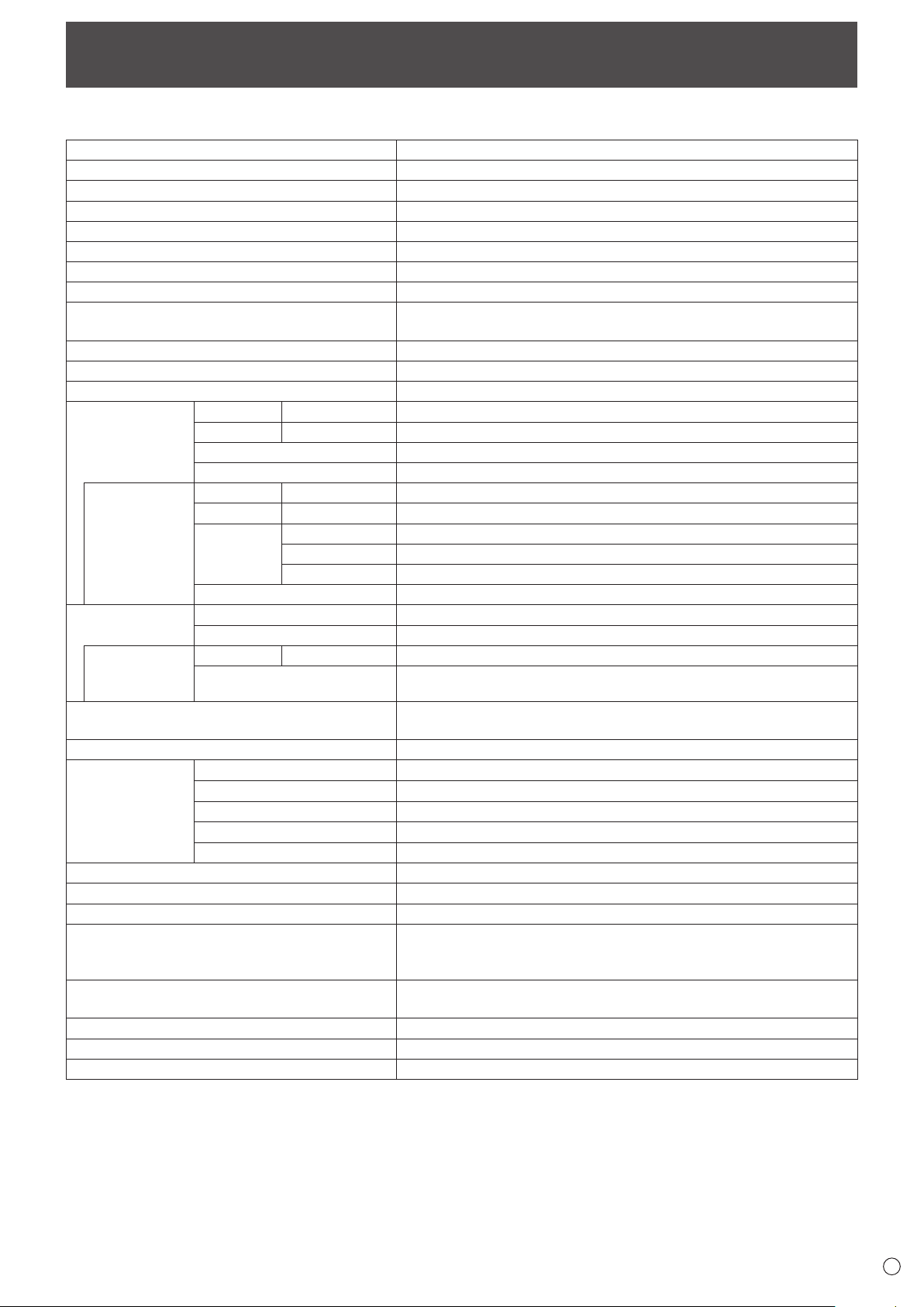
53
E
Specications
n
Product Specications
Model PN-L602B
LCD component
60" Class [60-1/16 inch (152.5cm) diagonal] TFT LCD
Max. resolution (pixels)
1920 x 1080
Max. colors
Approx. 1.06 billion colors
Pixel pitch
0.692 mm (H) × 0.692 mm (V)
Viewing angle
160° right/left/up/down (contrast ratio ≥ 10)
Screen active area inch (mm)
52-5/16 x 29-7/16 (1329.1 x 747.6)
Computer input signal
Digital (DVI 1.0 standard-compliant), Analog RGB (0.7 Vp-p) [75
Ω
]
Sync signal
Horizontal/vertical separate (TTL: positive/negative), Sync-on-green,
Composite sync (TTL: positive/negative)
Video color system
NTSC (3.58MHz)/NTSC (4.43MHz)/PAL/PAL-60/SECAM
Plug and play
VESA DDC2B
Power management
VESA DPMS, DVI DMPM
Input terminals
PC/AV
Digital
HDMI x 1
PC
Analog
Mini D-sub 15 pin, 3 rows x 1
Audio
3.5 mm mini stereo jack x 1
Serial (RS-232C)
D-sub 9 pin x 1
When PN-ZB01
(optional) is
attached
PC/AV
Digital
DVI-D 24 pin (HDCP compatible) x 1
PC
Analog
BNC
*
1
*
2
x 1
AV
Composite video
BNC x 1
S-video
x 1
Component BNC (Y, Cb/Pb, Cr/Pr) *
1
x 1
Audio
RCA pin (L/R) x 2
Output terminals
Audio
RCA pin (L/R) x 1
Serial (RS-232C)
D-sub 9 pin x 1
When PN-ZB01
(optional) is
attached
PC/AV
Digital
DVI-D 24 pin x 1
External speaker 7 W + 7 W
[6
Ω
]
LAN terminal
[
When PN-ZB01 (optional) is attached
]
10 BASE-T/100 BASE-TX
Speaker output 7 W + 7 W
Touch Panel
Detection method Infrared blocking detection method
Detection area inch (mm)
52-5/16 x 29-7/16 (1329.1 x 747.6)
PC connector USB (1.1 compliant)
Power supply Supplied from USB
Touch pen Ultrasonic communication method
Power requirement AC 100 V - 240 V, 2.0 A, 50/60 Hz
Operating temperature
*
3
*
4
41°F to 95°F (5°C to 35°C)
Operating humidity
*
4
20% to 80% (no condensation)
Power consumption
(Maximum / input signal waiting mode
*
5
/ standby
mode
*
6
)
165 W / 1.0 W / 1.0 W
Power consumption
[
When PN-ZB01 (optional) is attached
]
170 W
Dimensions (excluding protrusions) inch (mm)
Approx. 56-11/16 (W) x 4 (D) x 33-11/16 (H) (1,440 x 101 x 855)
Weight lbs. (kg)
Approx. 119.0 (54)
Weight [PN-ZB01 (optional)] lbs. (kg)
Approx. 1.102 (0.5)
*1 Cannot be used simultaneously.
*2 Does not support plug and play.
*3 Temperature condition may change when using the monitor together with the optional equipments recommended by SHARP.
In such cases, please check the temperature condition specied by the optional equipments.
*4 In addition, check the requirements of the computer and other devices to be connected, and make sure that all requirements are satised.
*5 When AUTO INPUT CHANGE is set to OFF.
*6 When STANDBY MODE is set to STANDARD. When STANDBY MODE is set to LOW POWER: 0.5 W
As a part of our policy of continuous improvement, SHARP reserves the right to make design and specication changes for product improvement
without prior notice. The performance specication gures indicated are nominal values of production units. There may be some deviations from
these values in individual units.
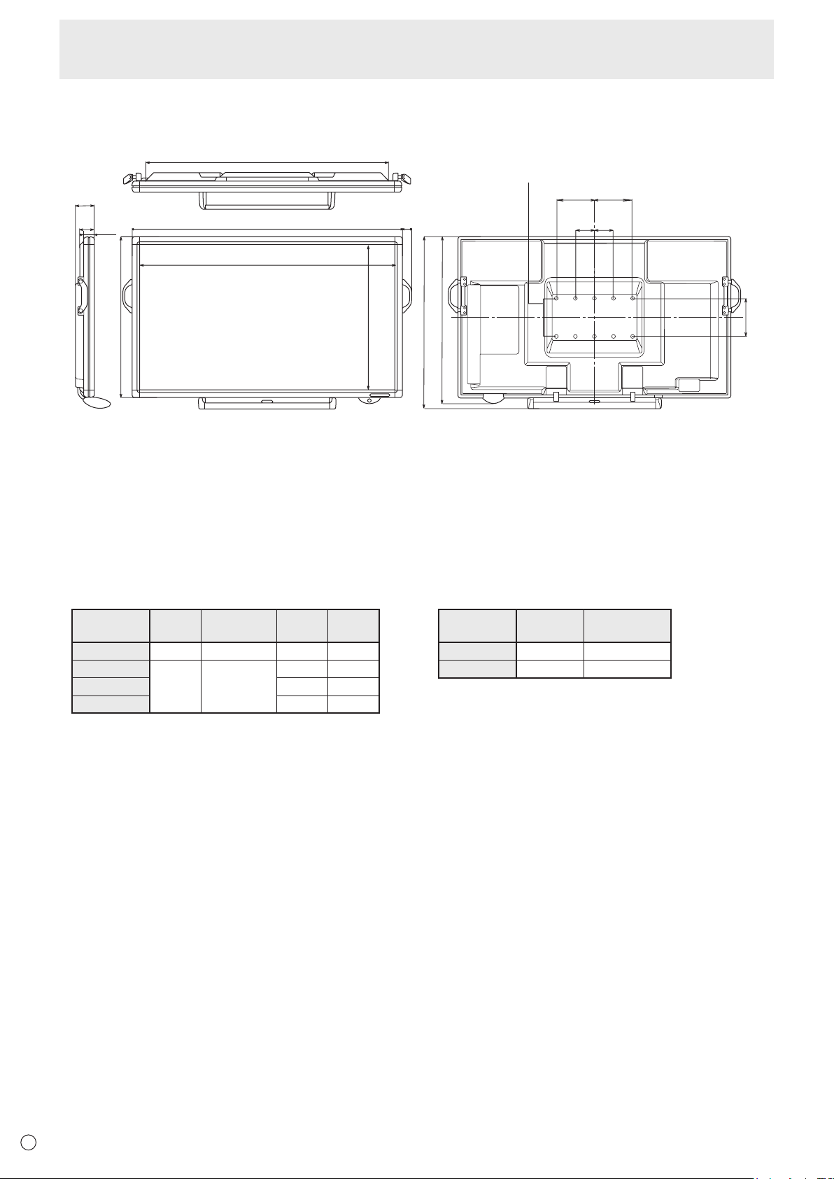
54
E
Specications
n
Dimensional Drawings
Note that the values shown are approximate values.
51-1/8 [1298]
56-11/16 [1440]
Opening height (30-1/2 [774])
Opening width (53-7/16 [1358])
1-7/8 [47]
33-11/16 [855]
2-3/16
[56]
3-1/16
[77.5]
4
[101]
34-7/8 [886]
36 [914]
VESA holes *
3-15/16
[100]
3-15/16
[100]
7-7/8
[200]
7-7/8
[200]
7-7/8 [200]
Unit: inch [mm]
When mounting the monitor, be sure to use a wall-mount bracket that complies with the VESA-compatible mounting method.
SHARP recommends using M6 screws and tighten the screws.
Note that screw hole depth of the monitor is 3/8 inch (10 mm). Loose mounting may cause the product to fall, resulting in
serious personal injuries as well as damage to the product. The screw and hole should come together with over 5/16 inch
(8 mm) length of thread. Use a bracket which has been approved for UL1678 standard, and which can endure at least 4 times
or more the weight of the monitor.
n
Power management
This monitor conforms to VESA DPMS and DVI DMPM. Both your video card and computer must support the same standard in
order for the monitor’s power management function to work.
DPMS: Display Power Management Signaling
DPMS Screen
Power
consumption
Hsync Vsync
ON STATE Display 165 W*
1
Yes Yes
STANDBY
No
display
1.0 W*
1
*
2
No Yes
SUSPEND Yes No
OFF STATE No No
*1 When PN-ZB01 (optional) is not connected.
*2 When AUTO INPUT CHANGE is set to OFF.
DMPM: Digital Monitor Power Management
DMPM Screen
Power
consumption
Monitor ON Display 165 W*
1
Active OFF No display 1.0 W*
1
*
2
n
DDC (plug and play)
The monitor supports the VESA DDC (Display Data Channel) standard.
DDC is a signal standard for plug and play between monitors and computers. Information about resolution and other parameters
is exchanged between the two. This function can be used if the computer supports DDC and it has been congured to detect
plug-and-play monitors.
There are several types of DDC, depending on the communication method used. This monitor supports DDC2B.
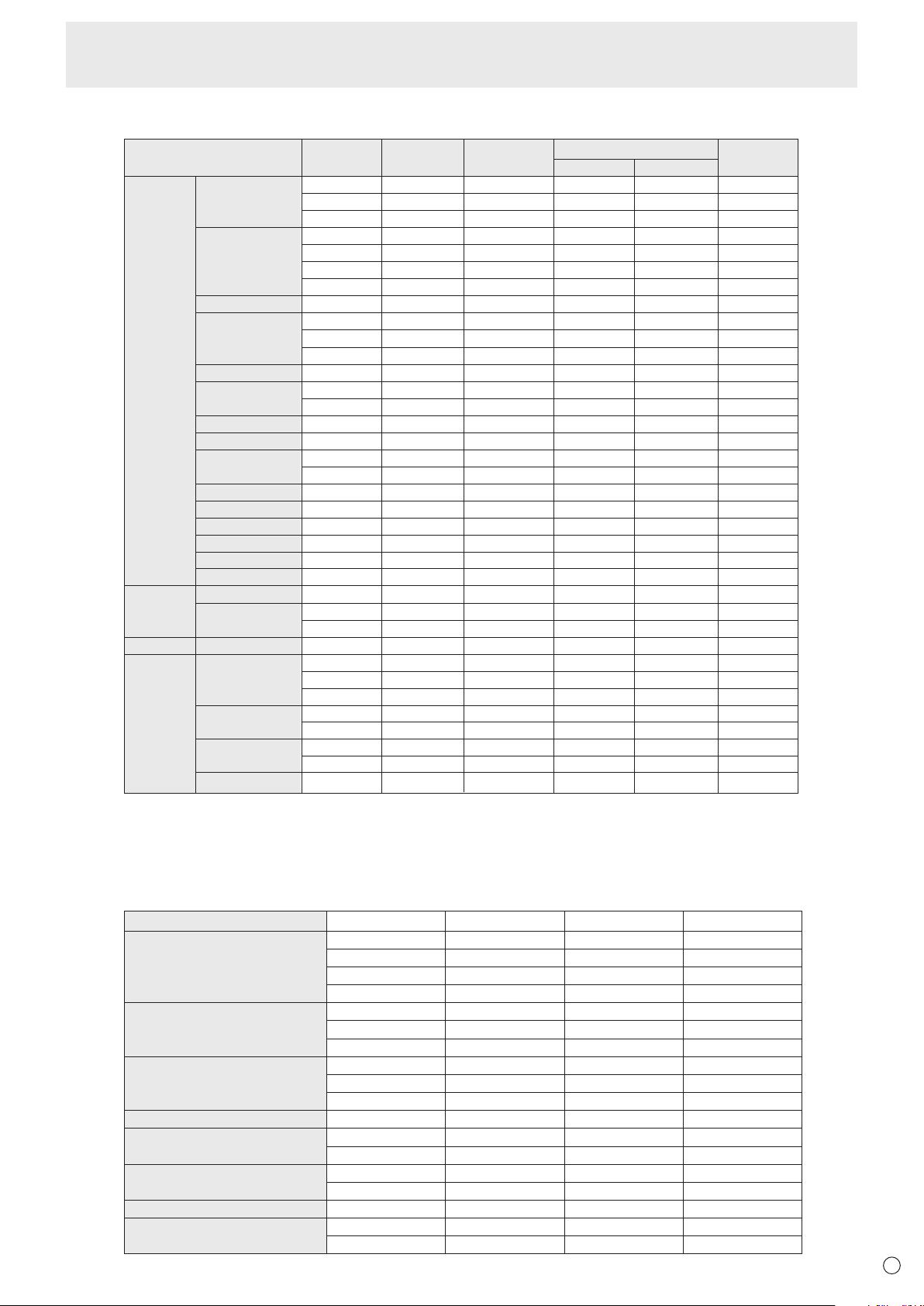
55
E
n
Compatible signal timing (PC)
VESA
Wide
US TEXT
Sun
Screen resolution Hsync VsyncDot frequency
Digital
640 × 480
800 × 600
848 × 480
1024 × 768
1152 × 864
1280 × 768
1280 × 800
1280 × 960
1280 × 1024
1360 × 768
1400 × 1050
1440 × 900
1600 × 1200
*1
1680 × 1050
1920 × 1200
*1
1280 × 720
1920 × 1080
720 × 400
1024 × 768
1152 × 900
1280 × 1024
1600 × 1000
31.5kHz
37.9kHz
37.5kHz
35.1kHz
37.9kHz
48.1kHz
46.9kHz
31.0kHz
48.4kHz
56.5kHz
60.0kHz
67.5kHz
47.8kHz
60.3kHz
49.7kHz
60.0kHz
64.0kHz
80.0kHz
47.7kHz
65.3kHz
55.9kHz
75.0kHz
65.3kHz
74.0kHz
44.7kHz
66.3kHz
67.5kHz
31.5kHz
48.3kHz
53.6kHz
56.6kHz
61.8kHz
71.8kHz
71.7kHz
81.1kHz
68.6kHz
60Hz
72Hz
75Hz
56Hz
60Hz
72Hz
75Hz
60Hz
60Hz
70Hz
75Hz
75Hz
60Hz
75Hz
60Hz
60Hz
60Hz
75Hz
60Hz
60Hz
60Hz
60Hz
60Hz
60Hz
60Hz
60Hz
60Hz
70Hz
60Hz
66Hz
70Hz
66Hz
76.2Hz
67.2Hz
76Hz
66Hz
25.175MHz
31.5MHz
31.5MHz
36.0MHz
40.0MHz
50.0MHz
49.5MHz
33.75MHz
65.0MHz
75.0MHz
78.75MHz
108.0MHz
79.5MHz
102.25MHz
83.5MHz
108.0MHz
108.0MHz
135.0MHz
85.5MHz
121.75MHz
106.5MHz
162.0MHz
146.25MHz
154.0MHz
74.4MHz
148.5MHz
148.5MHz
28.3MHz
64.13MHz
70.4MHz
74.25MHz
94.88MHz
108.23MHz
117.01MHz
134.99MHz
135.76MHz
Yes
Yes
Yes
-
Yes
Yes
Yes
Yes
Yes
Yes
Yes
Yes
Yes
Yes
Yes
Yes
Yes
Yes
Yes
Yes
Yes
Yes
Yes
Yes
Yes
Yes
Yes
Yes
-
-
-
-
-
-
-
-
Analog
(D-SUB/RGB*
2
)
Yes
Yes
Yes
Yes
Yes
Yes
Yes
Yes
Yes
Yes
Yes
Yes
Yes
Yes
Yes
Yes
Yes
Yes
Yes
Yes
Yes
Yes
Yes
Yes
Yes
Yes
Yes
Yes
Yes
Yes
Yes
Yes
Yes
Yes
Yes
Yes
DVI*
2
HDMI
Yes
Yes
Yes
-
Yes
Yes
Yes
-
Yes
Yes
Yes
Yes
-
-
Yes
Yes
Yes
Yes
Yes
Yes
-
Yes
Yes
Yes
Yes
Yes
Yes
Yes
-
-
-
-
-
-
-
-
*1 Displays a reduced image, except in Dot by Dot. In Dot by Dot, the image will be cut down to panel size then displayed.
*2 Available when the PN-ZB01 (optional) is attached.
* Allarecompliantonlywithnon-interlaced.
* DependingontheconnectedPC,imagesmaynotbedisplayedproperlyevenifthecompatiblesignaldescribedaboveisinput.
* ThefrequencyvaluesfortheSunarereferencevalues.
n
Compatible signal timing (AV)
Screen resolution Frequency DVI-D* HDMI Component
1920×1080p 24Hz - Yes -
50Hz Yes Yes Yes
59.94Hz Yes Yes Yes
60Hz Yes Yes Yes
1920×1080i 50Hz Yes Yes Yes
59.94Hz Yes Yes Yes
60Hz Yes Yes Yes
1280×720p 50Hz Yes Yes Yes
59.94Hz Yes Yes Yes
60Hz Yes Yes Yes
720×576p 50Hz Yes Yes Yes
720×480p 59.94Hz Yes Yes Yes
60Hz Yes Yes Yes
640×480p(VGA) 59.94Hz Yes Yes -
60Hz Yes Yes -
720(1440)×576i 50Hz - Yes Yes
720(1440)×480i 59.94Hz - Yes Yes
60Hz - Yes Yes
*AvailablewhenthePN-ZB01(optional)isattached.
Specications
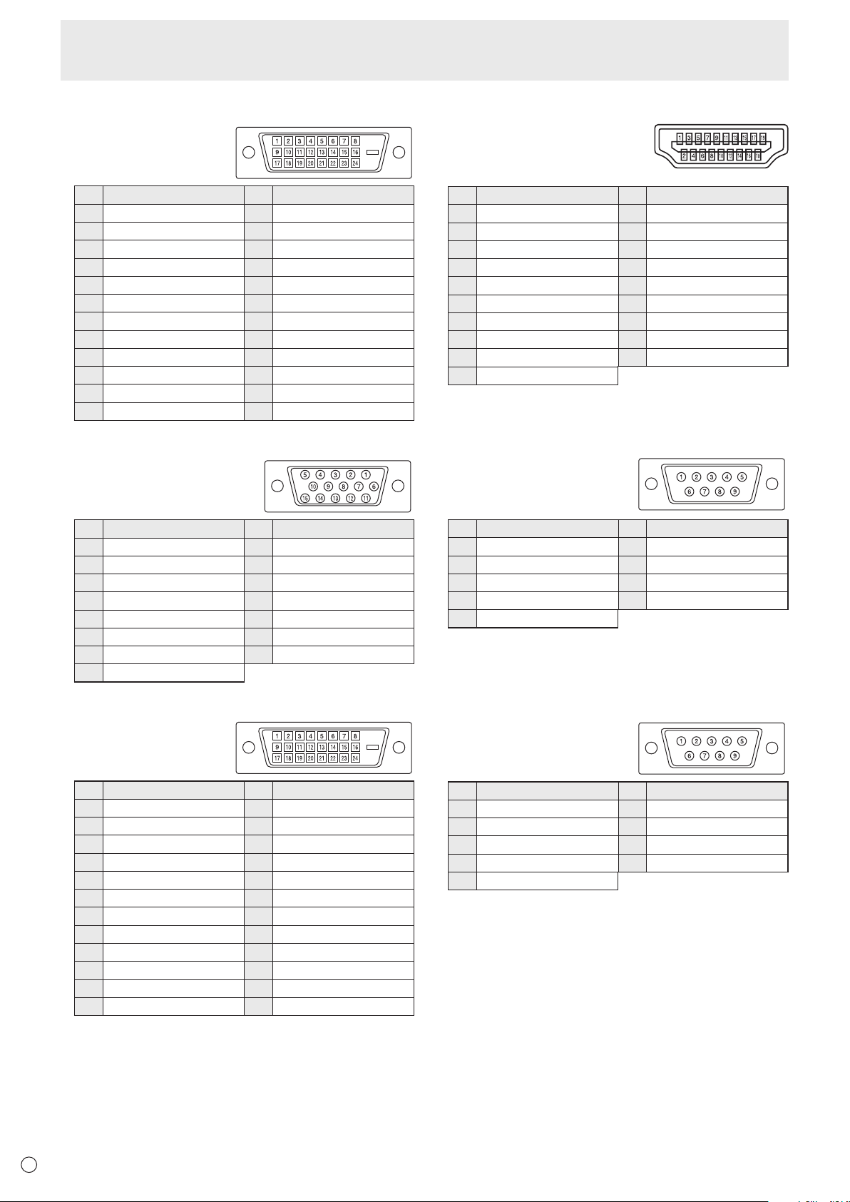
56
E
Specications
n
PC/AV DVI-D input terminal pins
(DVI-D 24 pin)
No. Function No. Function
1 TMDSdata2- 13 N.C.
2 TMDSdata2+ 14 +5V
3 TMDSdata2/4shield 15 GND
4 N.C. 16 Hot-plugdetection
5 N.C. 17 TMDSdata0-
6 DDCclock 18 TMDSdata0+
7 DDCdata 19 TMDSdata0/5shield
8 N.C. 20 N.C.
9 TMDSdata1- 21 N.C.
10 TMDSdata1+ 22 TMDSclockshield
11 TMDSdata1/3shield 23 TMDSclock+
12 N.C. 24 TMDSclock-
n
PC D-sub input terminal pins
(Mini D-sub 15 pin)
No. Function No. Function
1 Red video signal input 9 +5V
2 Greenvideosignalinput 10 GND
3 Bluevideosignalinput 11 N.C.
4 N.C. 12 DDCdata
5 GND 13 Hsyncsignalinput
6 GNDforredvideosignal 14 Vsyncsignalinput
7 GNDforgreenvideosignal 15 DDCclock
8 GNDforbluevideosignal
n
PC/AV DVI-D output terminal pins
(DVI-D 24 pin)
No. Function No. Function
1 TMDSdata2- 13 N.C.
2 TMDSdata2+ 14 +5V
3 TMDSdata2/4shield 15 GND
4 N.C. 16 Hot-plugdetection
5 N.C. 17 TMDSdata0-
6 DDCclock 18 TMDSdata0+
7 DDCdata 19 TMDSdata0/5shield
8 N.C. 20 N.C.
9 TMDSdata1- 21 N.C.
10 TMDSdata1+ 22 TMDSclockshield
11 TMDSdata1/3shield 23 TMDSclock+
12 N.C. 24 TMDSclock-
n
PC/AV HDMI input terminal pins
(HDMI
TM
Connector)
No. Function No. Function
1 TMDSdata2+ 11 TMDSclockshield
2 TMDSdata2shield 12 TMDSclock-
3 TMDSdata2- 13 CEC
4 TMDSdata1+ 14 N.C.
5 TMDSdata1shield 15 SCL
6 TMDSdata1- 16 SDA
7 TMDSdata0+ 17 DDC/CECGND
8 TMDSdata0shield 18 +5V
9 TMDSdata0- 19 Hot-plugdetection
10 TMDSclock+
n
RS-232C input terminal pins
(D-sub 9 pin)
No. Function No. Function
1 N.C. 6 N.C.
2 Transmitted data 7 N.C.
3 Received data 8 N.C.
4 N.C. 9 N.C.
5 GND
n
RS-232C output terminal pins
(D-sub 9 pin)
No. Function No. Function
1 N.C. 6 N.C.
2 Received data 7 N.C.
3 Transmitted data 8 N.C.
4 N.C. 9 N.C.
5 GND
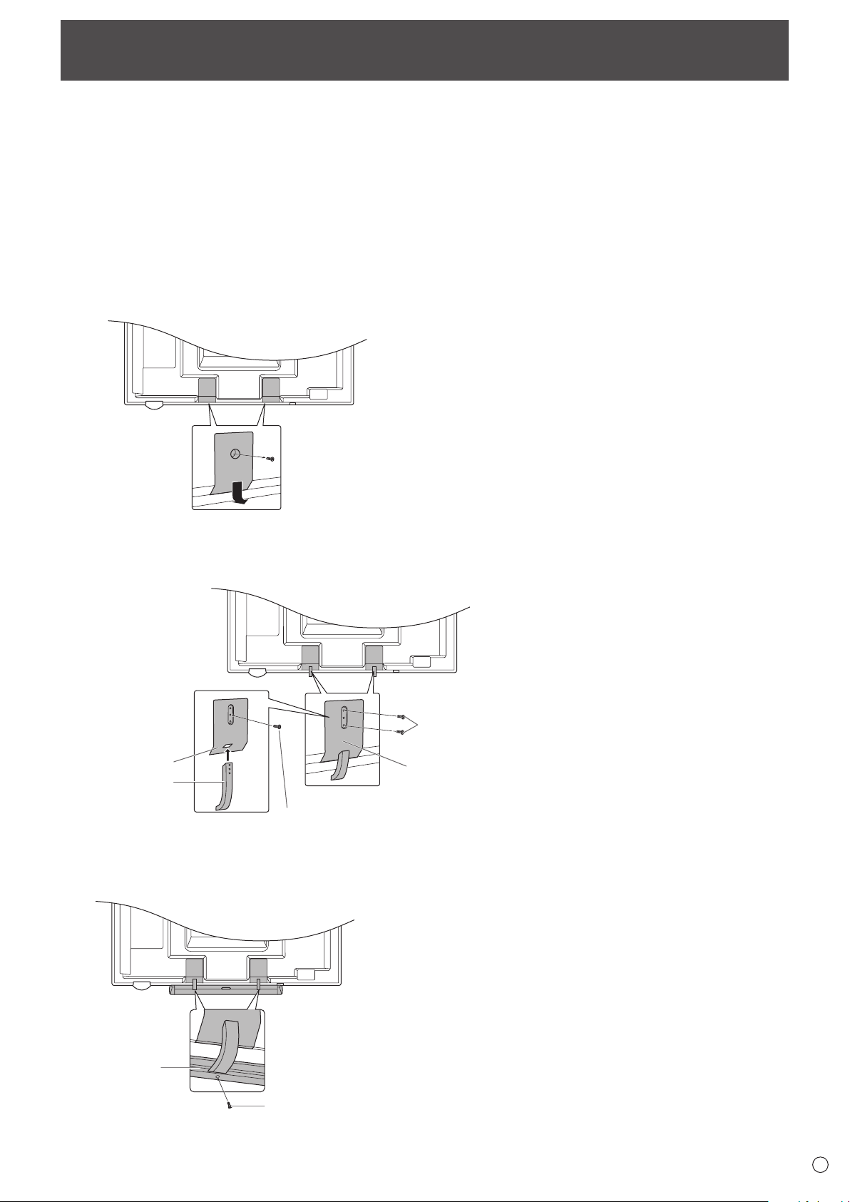
57
E
• Wheninstalling,removingormovingthemonitor,ensurethatthisiscarriedoutbyatleast2people.
• Besuretouseawall-mountbracketdesignedordesignatedformountingthemonitor.
• Thismonitorisdesignedtobeinstalledonaconcretewallorpillar.Reinforcedworkmightbenecessaryforsomematerials
such as plaster / thin plastic board / wood before starting installation.
This monitor and bracket must be installed on a wall which can endure at least 4 times or more the weight of the monitor.
Install by the most suitable method for the material and the structure.
• ToattachaVESA-compliantmountingbracket,useM6screwsthatare5/16inch(8mm)to3/8inch(10mm)longerthanthe
thickness of the mounting bracket.
• Aftermounting,pleasecarefullyensurethemonitorissecure,andnotabletocomeloosefromthewallormount.
• DonotuseanyscrewholesotherthanVESAholesforinstallation.
Mounting Precautions
(For SHARP dealers and service engineers)
n
Attaching the Tray
1. Remove the cover from the back of the monitor.
2. Secure the tray mounting tting.
Secureusingthescrewremovedinstep1and2M5tray
mounting screws (supplied).
(3)
(2)
(1)
M5 tray mounting screws
(supplied)
Tray mounting
fitting
Screw removed in step 1
Cover (supplied)
Bracket (supplied)
3. Secure the tray.
Insertthetrayintothetraymountingttingandsecurewith
2 M4 tray mounting screws (supplied).
Tray
(supplied)
M4 tray mounting screws
(supplied)

PN-L602BMuEN11K(1)