Issue 04/2019 Art. Nr. 7001-0056
Operating Manual
M (E2)
Drying and heating ovens with forced convection
and advanced program functions
Model Model version Art. No.
M 53 M053-230V 9010-0201, 9110-0201
M 115 M115-230V 9010-0202, 9110-0202
M 240 M240-230V 9010-0203, 9110-0203
M 400 M400-230V 9010-0204, 9110-0204
M 720 M720-230V 9010-0205, 9110-0205
BINDER GmbH
Address: Post office box 102, 78502 Tuttlingen, Germany Phone: +49 7462 2005 0
Fax: +49 7462 2005 100 Internet: http://www.binder-world.com
E-mail: info@binder-world.com Service Hotline: +49 7462 2005 555
Service Fax: +49 7462 2005 93 555 Service E-Mail: service@binder-world.com
Service Hotline USA: +1 866 885 9794 or +1 631 224 4340 x3
Service Hotline Asia Pacific: +852 390 705 04 or +852 390 705 03
Service Hotline Russia and CIS: +7 495 988 15 16

M (E2) 04/2019 page 2/71
Contents
1. SAFETY .................................................................................................................. 4
1.1 Legal considerations ........................................................................................................................... 4
1.2 Structure of the safety instructions ...................................................................................................... 4
1.2.1 Signal word panel ..................................................................................................................... 4
1.2.2 Safety alert symbol ................................................................................................................... 5
1.2.3 Pictograms ................................................................................................................................ 5
1.2.4 Word message panel structure ................................................................................................. 6
1.3 Localization / position of safety labels on the chamber ...................................................................... 6
1.4 Type plate ........................................................................................................................................... 7
1.5 General safety instructions on installing and operating the chambers ............................................... 8
1.6 Intended use ....................................................................................................................................... 9
2. CHAMBER DESCRIPTION .................................................................................. 10
2.1 Chamber overview ............................................................................................................................ 11
2.2 Control panel ..................................................................................................................................... 12
3. COMPLETENESS OF DELIVERY, TRANSPORTATION, STORAGE, AND
INSTALLATION .................................................................................................... 12
3.1 Unpacking, and checking equipment and completeness of delivery ................................................ 12
3.2 Guidelines for safe lifting and transportation .................................................................................... 13
3.3 Storage .............................................................................................................................................. 13
3.4 Location of installation and ambient conditions ................................................................................ 14
4. INSTALLATION AND CONNECTIONS................................................................ 15
4.1 Electrical connection ......................................................................................................................... 15
4.2 Connection to a suction plant (optional) ........................................................................................... 15
5. START UP ............................................................................................................ 16
5.1 Function overview of the MB1 display program controller ................................................................ 16
5.2 Operating modes ............................................................................................................................... 16
5.3 Performance after power failures ...................................................................................................... 17
5.4 Turning on the chamber .................................................................................................................... 17
6. CONTROLLER MB1 SETTINGS .......................................................................... 18
6.1 Selection of the menu language ....................................................................................................... 18
6.2 Overview of program controller MB1 displays .................................................................................. 19
6.3 Menu settings in the “User-settings” menu ....................................................................................... 20
6.4 Menu settings in the “User Level” menu ........................................................................................... 21
7. GRAPHIC REPRESENTATION OF THE HISTORICAL MEASUREMENT
(CHART RECORDER FUNCTION) ..................................................................... 22
7.1 Setting the storage rate ..................................................................................................................... 24
8. MANUAL MODE ................................................................................................... 25
8.1 Entering the set point values ............................................................................................................. 25
8.2 Performance after power failure in Manual Mode ............................................................................. 26
9. PROGRAM OPERATION ..................................................................................... 26
9.1 Menu-based program entry ............................................................................................................... 27
9.2 Selecting between set-point ramp and set-point step ....................................................................... 29
9.3 Program entry as set-point ramp or as set-point step ...................................................................... 29
9.4 Information on programming different temperature transitions ......................................................... 32
9.5 Repetition of a section or several sections within a program ........................................................... 33
9.6 Performance after power failure in Program Mode ........................................................................... 33

M (E2) 04/2019 page 3/71
9.7
Starting a previously entered program .............................................................................................. 34
9.8 Deleting a program............................................................................................................................ 34
9.9 Temperature profile template ............................................................................................................ 35
9.10 Program table template ..................................................................................................................... 36
10. TEMPERATURE SAFETY DEVICES ................................................................... 37
10.1 Temperature safety device class 2 (DIN 12880) .............................................................................. 37
10.2 Temperature safety device class 3.1 (DIN 12880) (available via BINDER INDIVIDUAL customized
solutions) ........................................................................................................................................... 38
11. OPTIONS .............................................................................................................. 39
11.1 APT-COM™ 4 Multi Management Software (option)........................................................................ 39
11.2 Ethernet interface .............................................................................................................................. 39
11.3 HEPA fresh air filter (option) ............................................................................................................. 39
11.4 Data logger kit (option) ...................................................................................................................... 40
11.5 Additional flexible Pt100-temperature sensor (option) ...................................................................... 40
11.6 Analog output for temperature (option) ............................................................................................. 40
11.7 Additional measuring channel for digital object temperature indicator with flexible temperature
sensor Pt 100 (option) ....................................................................................................................... 41
11.8 Mostly gas-tight version (option for M 53 and M 115) ...................................................................... 41
11.9 Inert gas connection with mostly gas-tight version (option for M 53 and M 115) ............................. 42
11.10 Keyboard locking (option) ................................................................................................................. 44
12. MAINTENANCE, CLEANING, AND SERVICE .................................................... 44
12.1 Maintenance intervals, service .......................................................................................................... 44
12.2 Cleaning and decontamination ......................................................................................................... 45
12.2.1 Cleaning .................................................................................................................................. 45
12.2.2 Decontamination ..................................................................................................................... 47
12.3 Sending the chamber back to BINDER GmbH ................................................................................. 48
13. DISPOSAL............................................................................................................ 48
13.1 Disposal of the transport packing ..................................................................................................... 48
13.2 Decommissioning .............................................................................................................................. 49
13.3 Disposal of the chamber in the Federal Republic of Germany ......................................................... 49
13.4 Disposal of the chamber in the member states of the EU except for the Federal Republic of
Germany ........................................................................................................................................... 50
13.5 Disposal of the chamber in non-member states of the EU ............................................................... 51
14. TROUBLESHOOTING ......................................................................................... 52
15. TECHNICAL DESCRIPTION ................................................................................ 53
15.1 Factory calibration and adjustment ................................................................................................... 53
15.2 Definition of usable volume ............................................................................................................... 53
15.3 Over current protection ..................................................................................................................... 54
15.4 Technical data ................................................................................................................................... 54
15.5 Equipment and options (extract) ....................................................................................................... 56
15.6 Accessories and spare parts (extract) .............................................................................................. 57
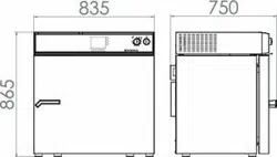
15.7 Dimensions M 53 .............................................................................................................................. 58
15.8 Dimensions M 115 ............................................................................................................................ 59
15.9 Dimensions M 240 ............................................................................................................................ 60
15.10 Dimensions M 400 ............................................................................................................................ 61
15.11 Dimensions M 720 ............................................................................................................................ 62
16. EU DECLARATION OF CONFORMITY ............................................................... 63
17. PRODUCT REGISTRATION ................................................................................ 65
18. CONTAMINATION CLEARANCE CERTIFICATE ............................................... 66
18.1 For chambers located outside the USA and Canada ....................................................................... 66
18.2 For chambers located in the USA and Canada ................................................................................ 69
M (E2) 04/2019 page 4/71
Dear customer,
For the correct operation of the chambers, it is important that you read this operating manual completely
and carefully and observe all instructions as indicated. Failure to read, understand and follow the instruc-
tions may result in personal injury. It can also lead to damage to the chamber and/or poor equipment
performance.
1. Safety
This operating manual is part of the components of delivery. Always keep it handy for reference. The
device should only be operated by laboratory personnel especially trained for this purpose and familiar
with all precautionary measures required for working in a laboratory. Observe the national regulations on
minimum age of laboratory personnel. To avoid injuries and damage observe the safety instructions of
the operating manual.
WARNING
Failure to observe the safety instructions.
may result in serious injuries and chamber damage.
Observe the safety instructions in this operating manual.
Carefully read the complete operating instructions of the chambers.
1.1 Legal considerations
This operating manual is for informational purposes only. It contains information for installing, start-up,
operation and maintenance of the product. Note: the contents and the product described are subject to
change without notice.
Understanding and observing the instructions in this operating manual are prerequisites for hazard-free
use and safety during operation and maintenance. In no event shall BINDER be held liable for any dam-
ages, direct or incidental arising out of or related to the use of this manual.
This operating manual cannot cover all conceivable applications. If you would like additional information,
or if special problems arise that are not sufficiently addressed in this manual, please ask your dealer or
contact us directly by phone at the number located on page one of this manual
Furthermore, we emphasize that the contents of this operating manual are not part of an earlier or exist-
ing agreement, description, or legal relationship, nor do they modify such a relationship. All obligations on
the part of BINDER derive from the respective purchase contract, which also contains the entire and ex-
clusively valid statement of warranty administration. The statements in this manual neither augment nor
restrict the contractual warranty provisions.
1.2 Structure of the safety instructions
In this operating manual, the following safety definitions and symbols indicate dangerous situations fol-
lowing the harmonization of ISO 3864-2 and ANSI Z535.6.
1.2.1 Signal word panel
Depending on the probability of serious consequences, potential dangers are identified with a signal
word, the corresponding safety color, and if appropriate, the safety alert symbol.
DANGER
Indicates an imminently hazardous situation that, if not avoided, will result in death or serious
(irreversible) injury.
M (E2) 04/2019 page 5/71
WARNING
Indicates a potentially hazardous situation which, if not avoided, could result in death or serious
(irreversible) injury
CAUTION
Indicates a potentially hazardous situation which, if not avoided, may result in moderate or minor
(reversible) injury.
CAUTION
Indicates a potentially hazardous situation which, if not avoided, may result in damage to the product
and/or its functions or of a property in its proximity.
1.2.2 Safety alert symbol
Use of the safety alert symbol indicates a risk of injury.
Observe all measures that are marked with the safety alert symbol in order to avoid death or
injury.
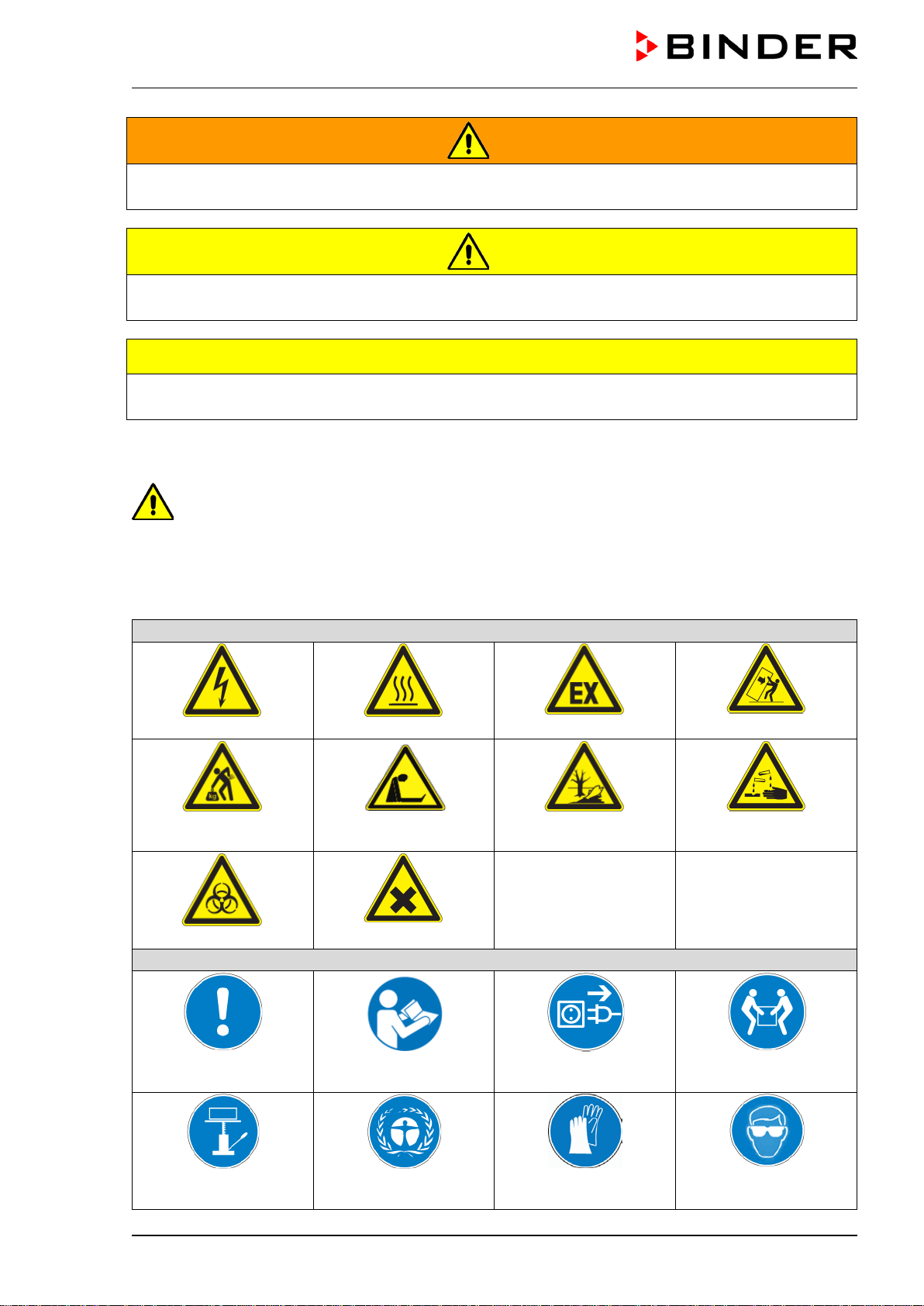
1.2.3 Pictograms
Warning signs
Electrical hazard
Hot surface
Explosive atmosphere
Stability hazard
Lifting hazard
Suffocation hazard
Pollution Hazard
Risk of corrosion and /
or chemical burns
Biohazard
Harmful substances
Mandatory action signs
Mandatory regulation
Read operating
instructions
Disconnect the power
plug
Lift with several persons
Lift with mechanical
assistance
Environment protection
Wear protective gloves
Wear safety goggles
M (E2) 04/2019 page 6/71
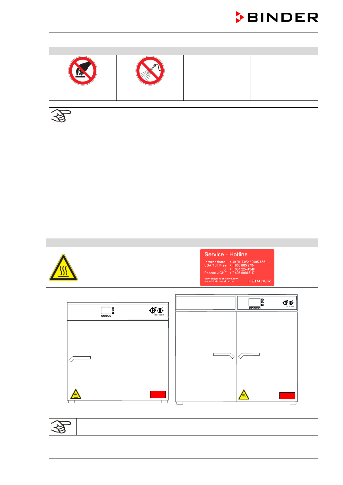
Prohibition signs
Do NOT touch
Do NOT spray with
water
Information to be observed in order to ensure optimum function of the product.
1.2.4 Word message panel structure
Type / cause of hazard.
Possible consequences.
Instruction how to avoid the hazard: prohibition
Instruction how to avoid the hazard: mandatory action
Observe all other notes and information not necessarily emphasized in the same way, in order to avoid
disruptions that could result in direct or indirect injury or property damage.
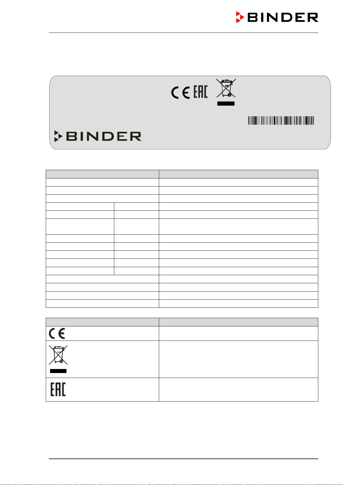
1.3 Localization / position of safety labels on the chamber
The following labels are located on the chamber:
Pictograms (Warning signs)
Service label
Hot surface
• Outer chamber door
• On the chamber rear next to the ex-
haust duct
6
8
ENTE
R
ENT
ENT
ENT
ER
ENT
ER
ENT
Figure 1: Position of labels on the chamber front
Keep safety labels complete and legible.
Replace safety labels that are no longer legible. Contact BINDER service for these replacements.
M (E2) 04/2019 page 7/71
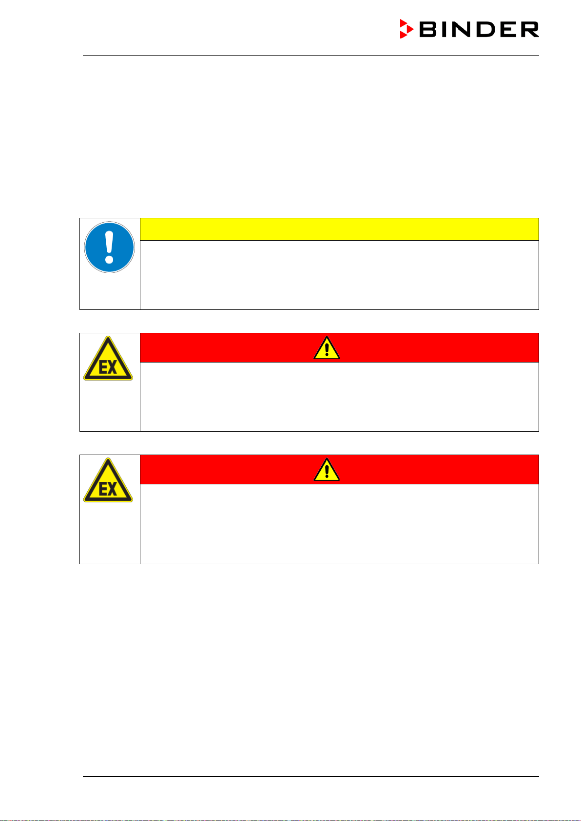
1.4 Type plate
The type plate sticks to the left side of the chamber, bottom right-hand.
Figure 2: Type plate (example of M 115 regular chamber)
Indications of the type plate (example)
Information
BINDER
Manufacturer BINDER GmbH
M 115
Model designation
Drying and heating oven
Chamber name
Serial No.
000000000000
Serial no. of the chamber
Built
2017
Year of construction
Nominal temperature
300 °C
572 °F
Nominal temperature
IP protection
20
IP type of protection acc. to EN 60529
Temp. safety device
DIN 12880
Temperature safety device acc. to standard DIN 12880
Class
2.0
Class of temperature safety device
Art. No.
9010-0202
Art. no. of the chamber
Project No.
---
Optional: Special application acc. to project no.
1,60 kW
Nominal power
230 V 1 N ~
Nominal voltage
±
10%, phase indication
7,0 A
Nominal current
50/60 Hz
Power frequency
Symbol on the type plate (example)
Information
CE conformity marking
Electrical and electronic equipment manufactured / placed
on the market in the EU after 13 August 2005 and to be
disposed of in a separate collection according to directive
2012/19/EU on waste electrical and electronic equipment
(WEEE).
The chamber is certified according to Customs Union
Technical Regulation (CU TR) for the Eurasian Economic
Union (Russia, Belarus, Armenia, Kazakhstan Kyrgyzstan).
Nominal temp.
300 °C
1,60 kW / 7,0 A
572 °F
230 V / 50 Hz
IP protection
20
230 V / 60 Hz
Safety device
DIN 12880
1 N ~
Class
2.0
Art. No.
9010-0202
Project No.
Built
2017
Drying and heating oven
BINDER GmbH
Im Mittleren Ösch 5
78532 Tuttlingen / Germany
www.binder-world.com
M 115
E2
Serial No. 00000000000000
Made in Germany
M (E2) 04/2019 page 8/71
1.5 General safety instructions on installing and operating the chambers
With regard to operating the chambers and to the installation location, please observe the DGUV guide-
lines 213-850 on safe working in laboratories (formerly BGI/GUV-I 850-0, BGR/GUV-R 120 or ZH 1/119,
issued by the employers’ liability insurance association) (for Germany).
BINDER GmbH is only responsible for the safety features of the chamber provided skilled electricians or
qualified personnel authorized by BINDER perform all maintenance and repair, and if components relat-
ing to chamber safety are replaced in the event of failure with original spare parts.
To operate the chamber, use only original BINDER accessories or accessories from third-party suppliers
authorized by BINDER. The user is responsible for any risk caused by using unauthorized accessories.
CAUTION
Danger of overheating.
Damage to the chamber.
Do NOT install the chamber in unventilated recesses.
Ensure sufficient ventilation for dispersal of the heat.
Do not operate the chambers in hazardous locations.
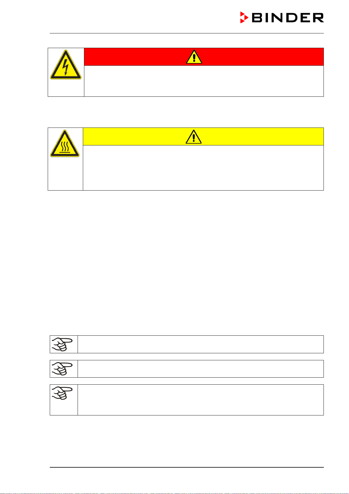
DANGER
Explosion hazard.
Danger of death.
Do NOT operate the chamber in potentially explosive areas.
KEEP explosive dust or air-solvent mixtures AWAY from the chamber.
The chambers do not dispose of any measures of explosion protection.
DANGER
Explosion hazard.
Danger of death.
Do NOT introduce any substance into the chamber which is combustible
or explosive at
working temperature.
NO explosive dust or air-solvent mixture in the inner chamber.
Any solvent contained in the charging material must not be explosive or inflammable. I.e., irrespective of
the solvent concentration in the steam room, NO explosive mixture with air must form. The temperature
inside the chamber must lie below the flash point or below the sublimation point of the charging material.
Familiarize yourself with the physical and chemical properties of the charging material, as well as the
contained moisture constituent and its behavior with the addition of heat energy.
Familiarize yourself with any potential health risks caused by the charging material, the contained mois-
ture constituent or by reaction products that may arise during the temperature process. Take adequate
measures to exclude such risks prior to putting the chamber into operation.
M (E2) 04/2019 page 9/71
DANGER
Electrical hazard.
Danger of death.
The chamber must NOT become wet during operation or maintenance.
The chambers were produced in accordance with VDE regulations and were routinely tested in accord-
ance to VDE 0411-1 (IEC 61010-1).
During and shortly after operation, the temperature of the inner surfaces almost equals the set-point.
CAUTION
The inner chamber, the door gasket, and the exhaust duct will become hot during
operation.
Danger of burning.
Do NOT touch the inner surfaces, the door gasket, the exhaust duct or the charging
material during operation.
1.6 Intended use
Drying and heating ovens with forced convection and advanced program functions M are suitable for
drying and heat treatment of solid or pulverized charging material, as well as bulk material, using the
supply of heat. They can be used for drying purposes but are specially designed for solving all the prob-
lems which occur during material and ageing tests.
The chambers are suitable for harmless materials. A mixture of any component of the charging material
with air must NOT be explosive. The operating temperature must lie below the flash point or below the
sublimation point of the charging material. Any component of the charging material must NOT be able to
release toxic gases.
Other applications are not approved.
The chambers are not classified as medical devices as defined by the Medical Device Directive
93/42/EEC.
Do NOT use the chambers for drying processes when large quantities of vapor would form and result in
condensation.
Due to the special demands of the Medical Device Directive (MDD), these chamber are not
qualified for sterilization of medical devices as defined by the directive 93/42/EWG.
Following the instructions in this operating manual and conducting regular maintenance work
(chap. 12) are part of the intended use.
The charging material shall not contain any corrosive ingredients that may damage the ma-
chine components made of stainless steel, aluminum, and copper. Such ingredients include
in particular acids and halides. Any corrosive damage caused by such ingredients is exclud-
ed from liability by BINDER GmbH.
M (E2) 04/2019 page 10/71
The chambers do not dispose of any measures of explosion protection.
DANGER
Explosion or implosion hazard.
Danger of poisoning.
Danger of death.
∅ Do NOT introduce any substance combustible or explosive at working temperature in
to
the chamber, in particular no energy sources such as batteries or lithium-ion batteries
∅ NO explosive dust or air-solvent mixture in the inner chamber.
∅ Do NOT introduce any substance which could lead to release of toxic gases.
In case of foreseeable use of the chamber there is no risk for the user through the integration of the
chamber into systems or by special environmental or operating conditions in the sense of EN 61010-
1:2010. For this, the intended use of the chamber and all its connections must be observed.
2. Chamber description
The drying and heating ovens with forced convection and advanced program functions APT.line™ M are
specially developed precision warming chamber with high capacity. They are equipped with a multifunc-
tional microprocessor display controller with a digital display accurate to one-tenth of a degree. With their
comprehensive program control functions, they allow the high precision performance of temperature cy-
cles with fast heating-up phases.
The APT.line™ preheating chamber system guarantees high level of spatial and time-based temperature
precision, thanks to the direct and distributed air circulation into the interior. The fan supports exact at-
tainment and maintenance of the desired temperature accuracy.
The high-quality housing insulation ensures both a low noise mode of operation and a consistently low
housing temperature. The inner chamber, the pre-heating chamber and the interior side of the doors are
all made of stainless V2A (German material no. 1.4301, US equivalent AISI 304). When operating the
chamber at temperatures above 150 °C / 302 °F, the impact of the oxygen in the air may cause discolora-
tion of the metallic surfaces (yellowish-brown or blue) by natural oxidation processes. These colorations
are harmless and will in no way impair the function or quality of the chamber. The housing is RAL 7035
powder-coated. All corners and edges are also completely coated.
All chamber functions are easy and comfortable to use thanks to their clear arrangement. Major features
are easy cleaning of all chamber parts and avoidance of undesired contamination.
The chambers are equipped with a serial interface RS 422 for computer communication, e.g. with the
APT-COM™ 4 Multi Management Software (option, chap. 11.1) For further options, see chap. 15.4.
The M 720
model is equipped with four castors. Both front castors can be easily locked via the attached
brakes.
At an ambient temperature of +18 °C up to +40 °C / 64.4 °F to 104 °F, you can operate the chamber in a
temperature range from 5 °C / 9 °F above ambient temperature up to 300 °C / 572 °F.
M (E2) 04/2019 page 11/71
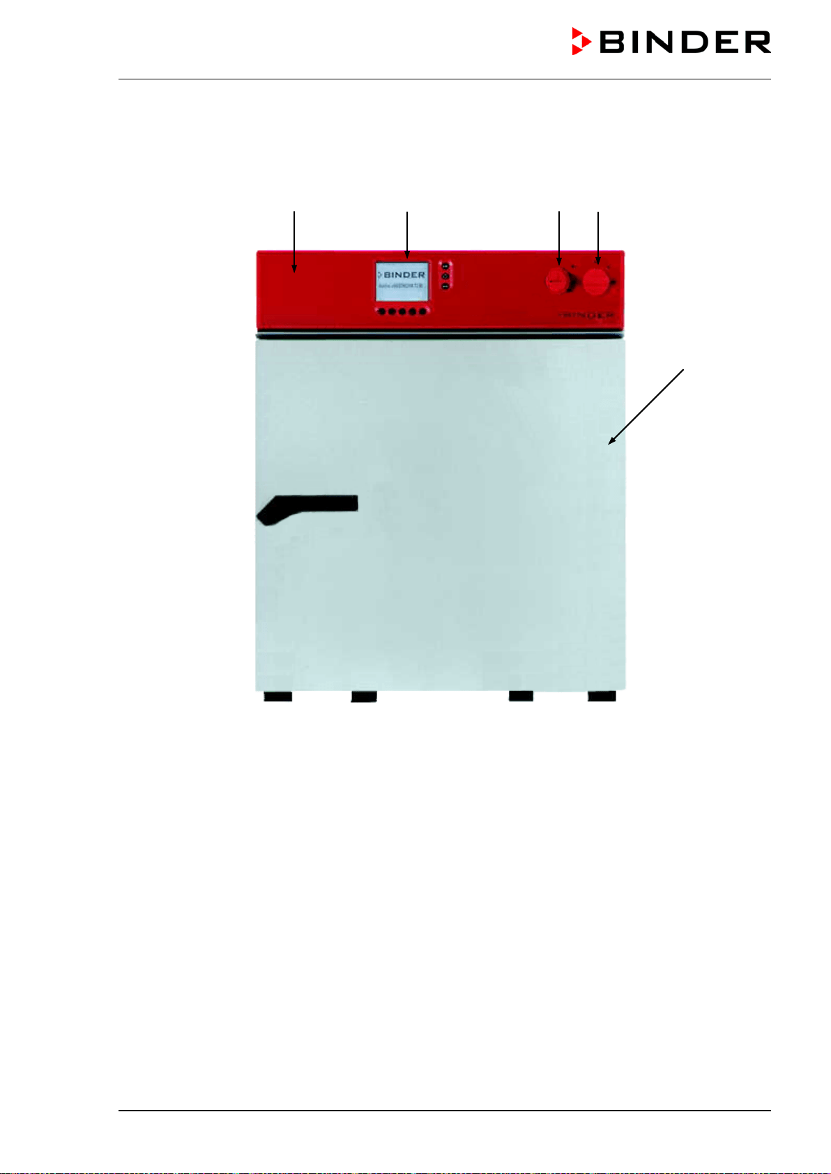
2.1 Chamber overview
Figure 3: Drying and heating oven M 53
(A) Instrument panel
(B) Microprocessor program controller MB1
(C) Temperature safety device class 2, according to DIN 12880
(D) Main power switch ON/OFF
(E) Outer door
(A) (B) (C) (D)
(E)
M (E2) 04/2019 page 12/71
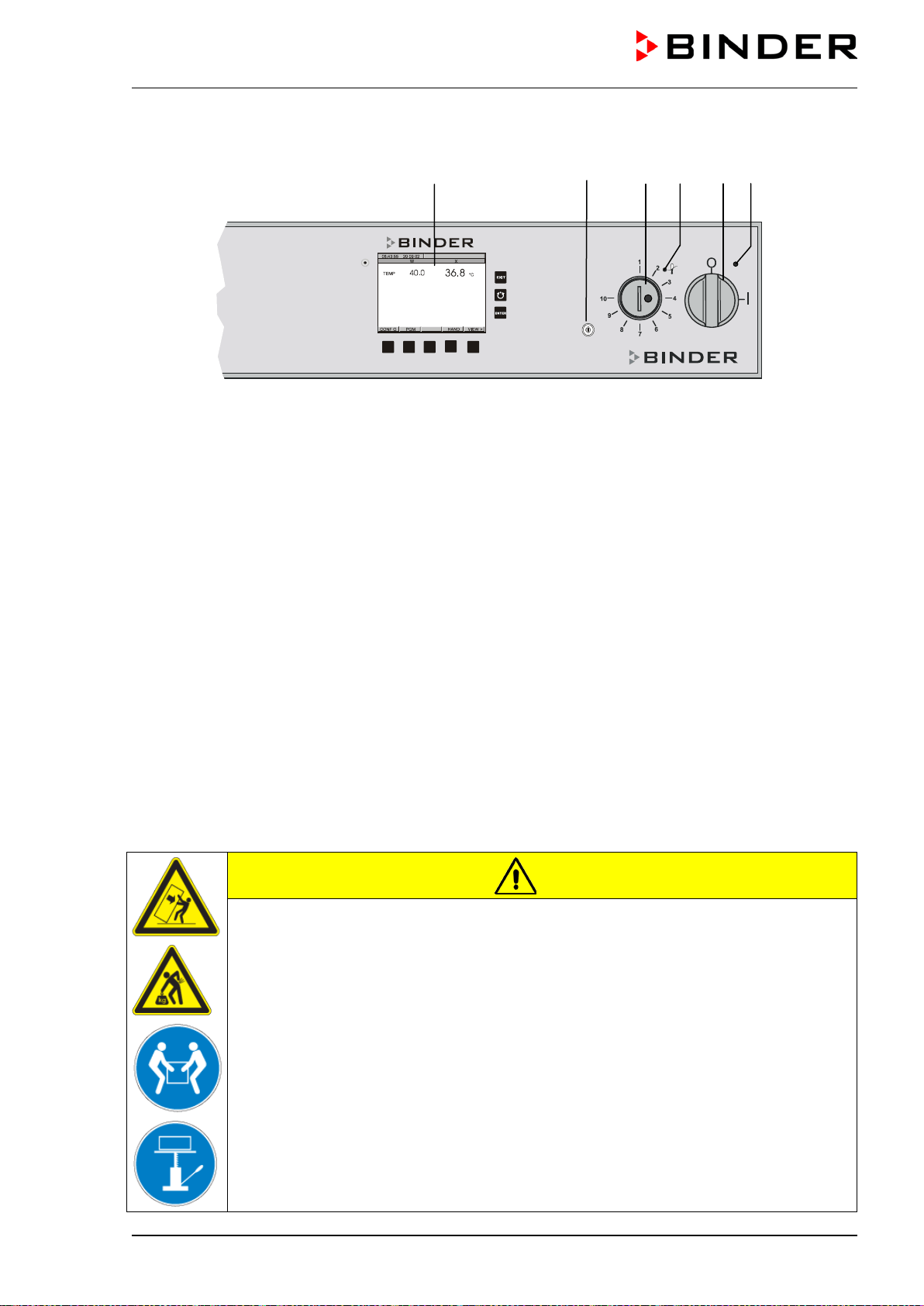
2.2 Control panel
Figure 4: Control panel for M with key switch (option)
(1) Green pilot lamp: ready for operation
(2) Main power switch ON/OFF
(3a) Red pilot lamp of the temperature safety device class 2
(3) Temperature safety device class 2
(4) Display program controller MB1
(5) Key switch (with option keyboard locking, chap. 11.10)
3. Completeness of delivery, transportation, storage, and installa-
tion
3.1 Unpacking, and checking equipment and completeness of delivery
After unpacking, please check the chamber and its optional accessories, if any, based on the delivery
receipt for completeness and for transportation damage. Inform the carrier immediately if transportation
damage has occurred.
The final tests of the manufacturer may cause traces of the shelves on the inner surfaces. This has no
impact on the function and performance of the chamber.
Please remove any transportation protection devices and adhesives in/on the chamber and on the doors
and take out the operating manuals and accessory equipment.
CAUTION
Sliding or tilting of the chamber.
Damage to the chamber.
Risk of injury by lifting heavy loads.
Do NOT lift or transport the chamber using either the door or the handle.
Do NOT lift chambers size 400 and 720 by hand.
Lift chambers size 53, 115 and 240 near the 4 chamber feet from the pallet with the aid
of 4 people.
Lift chambers size 400 and 720 using technical devices (fork lifter) from the pallet. Set
the fork lifter only from the rear in the middle of the chamber. Make sure to place all
the lateral supports of the chamber on the forks.
(4)
(5) (3) (3a) (2) (1)
M (E2) 04/2019 page 13/71
If you need to return the chamber, please use the original packing and observe the guidelines for safe
lifting and transportation (chap. 3.2).
For disposal of the transport packing, see chap. 13.1.
Note on second-hand chambers (Ex-Demo-Units):
Second-hand chambers are chambers that were used for a short time for tests or exhibitions. They are
thoroughly tested before resale. BINDER ensures that the chamber is technically sound and will work
flawlessly.
Second-hand chambers are marked with a sticker on the chamber door. Please remove the sticker be-
fore commissioning the chamber.
3.2 Guidelines for safe lifting and transportation
The front castors of the M 720 can be blocked by brakes. Please move the chambers with castors only
when empty and on an even surface, otherwise the castors may be damaged. After operation, please
observe the guidelines for temporarily decommissioning the chamber (chap. 13.2).
CAUTION
Sliding or tilting of the chamber.
Damage to the chamber.
Risk of injury by lifting heavy loads.
Transport the chamber in its original packaging only.
For moving or shipping, secure the chamber with transport straps
Do NOT lift or transport the chamber using either the door or the handle.
Do NOT lift chambers size 400 and 720 by hand.
Lift chambers size 53, 115 and 240 near the 4 chamber feet with the aid of 4 people
and place it on a transport pallet with wheels. Push the pallet to the desired site and
then lift the chamber near the 4 chamber feet from the pallet.
Place chambers size 400 and 720 using technical devices (fork lifter) on the transport
pallet. Set the fork lifter only from the rear in the middle of the chamber. Make sure to
place all the lateral supports of the chamber on the forks.
Transport chambers size 400 and 720 ONLY with the original transport pallet. Set the
fork lifter only to the pallet. Without the pallet the chamber is in imminent danger of
overturning.
• Permissible ambient temperature range during transport: -10 °C to +60 °C / 14 °F to 140 °F.
You can order transport packing and pallets for moving or shipping purposes from BINDER Service.
3.3 Storage
Intermediate storage of the chamber is possible in a closed and dry room. Observe the guidelines for
temporary decommissioning (chap. 13.2).
• Permissible ambient temperature range during storage: -10 °C to +60 °C / 14 °F to 140 °F.
• Permissible ambient humidity: max. 70 % r.H., non-condensing
When after storage in a cold location you transfer the chamber to its warmer installation site, condensa-
tion may form. Before start-up, wait at least one hour until the chamber has attained ambient temperature
and is completely dry.
M (E2) 04/2019 page 14/71
3.4 Location of installation and ambient conditions
Set up the chamber on a flat, even and non-flammable surface, free from vibration, and in a well-
ventilated, dry location and align it using a spirit level. The site of installation must be capable of support-
ing the chamber’s weight (see technical data, chap. 15.3). The chambers are designed for setting up
inside a building (indoor use).
CAUTION
Danger of overheating.
Damage to the chamber.
Do NOT set up chambers in non-ventilated recesses.
Ensure sufficient ventilation for dispersal of the heat.
• Permissible ambient temperature range during operation: +18 °C up to +40 °C / 64.4 °F to 104 °F. At
elevated ambient temperature values, fluctuations in temperature can occur.
The ambient temperature should not be substantially higher than the indicated ambient tem-
perature of +25 °C / 77 °F to which the specified technical data relate. In the case of different
ambient conditions, deviations from the indicated data are possible.
• Permissible ambient humidity: 70 % r.H. max., non-condensing.
• Installation height: max. 2000 m / 6562 ft. above sea level.
When placing several chambers of the same size side by side, maintain a minimum distance of 250 mm /
9.84 in between each chamber. Wall distances: rear 100 mm / 3.94 in, sides 160 mm / 6.29 in.
CAUTION
Danger by stacking.
Damage to the chambers.
Do NOT place the chambers on top of each other.
To completely separate the chamber from the power supply, you must disconnect the power plug. Install
the unit in a way that the power plug is easily accessible and can be easily pulled in case of danger.
For the user there is no risk of temporary overvoltages in the sense of EN 61010-1:2010.
Do not install or operate the chambers in potentially explosive areas.
DANGER
Explosion hazard.
Danger of death.
Do NOT operate the chamber in potentially explosive areas.
KEEP explosive dust or air-solvent mixtures AWAY from the vicinity of the chamber.
CAUTION
The exhaust duct will become hot during operation.
Danger of burning.
Do NOT touch the exhaust duct during operation.
M (E2) 04/2019 page 15/71
4. Installation and connections
4.1 Electrical connection
The chambers are supplied ready for connection. They come with a fixed power connection cable of at
least 1800 mm / 70.87 in in length.
Model Power plug
Nominal voltage
±
10% at the
indicated power frequency
Current type
M 53, M 115, M 240 Shockproof plug
230 V at 50 Hz
230 V at 60 Hz
1N~
M 400, M 720 CEE plug 5 poles
400 V at 50 Hz
400 V at 60 Hz
3N~
• The domestic socket must also provide a protective conductor. Make sure that the connection of the
protective conductor of the domestic installations to the chamber’s protective conductor meets the lat-
est technology. The protective conductors of the socket and plug must be compatible!
• Prior to connection and start-up, check the power supply voltage. Compare the values to the specified
data on the chamber’s type plate (chamber front behind the door, bottom left-hand, see chap. 1.4)
• When connecting, please observe the regulations specified by the local electricity supply company as
well as the VDE directives (for Germany). We recommend the use of a residual current circuit breaker.
• Pollution degree (acc. to IEC 61010-1): 2
• Over-voltage category (acc. to IEC 61010-1): II
CAUTION
Danger of incorrect power supply voltage.
Damage to the equipment.
Check the power supply voltage before connection and start-up.
Compare the power supply voltage with the data indicated on the type plate.
See also electrical data (chap. 15.3).
To completely separate the chamber from the power supply, you must disconnect the power
plug. Install the chamber in a way that the power plug is easily accessible and can be easily
pulled in case of danger.
4.2 Connection to a suction plant (optional)
When directly connecting a suction plant the spatial temperature exactitude, the heating-up and the re-
covering times and the maximum temperature will be negatively influenced. So no suction plant should be
directly connected to the exhaust duct.
Active suction from the chamber must only be effected together with extraneous air. Perforate
the connecting piece to the suction device or place an exhaust funnel at some distance to the
exhaust duct.
CAUTION
The exhaust duct will become hot during operation.
Danger of burning.
Do NOT touch the exhaust duct during operation.
M (E2) 04/2019 page 16/71
5. Start up
After connecting the electrical supply (chap. 4.1), turn on the chamber via the main power switch (2).
Warming chambers may release odors in the first few days after commissioning. This is not a quality de-
fect. To reduce odors quickly we recommend heating up the chamber to its nominal temperature for one
day and in a well-ventilated location.
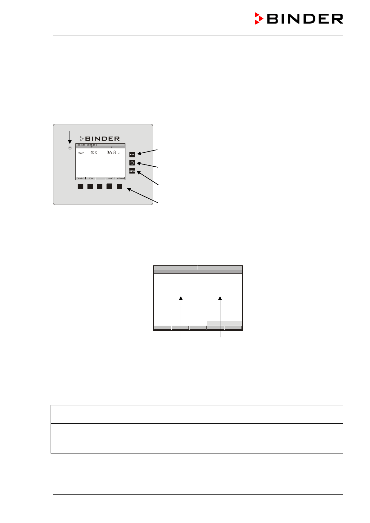
5.1 Function overview of the MB1 display program controller
Pilot lamp: Ready for operation
EXIT button (to exit a menu point)
AUTOMATIC button (to start a previously entered program)
ENTER button (to confirm a selection)
Navigation buttons (functions are assigned by the menu)
Figure 5: Display program controller MB1
The program controller MB1 controls the temperature inside the chamber (range: 5 °C above ambient
temperature up to 300 °C).
You can enter the desired set point values in Manual Mode or Program Mode (chap. 5.2) in the display
controller.
W
X
08:43:55 15.12.13
CONFIG
VIEW->
PGM
TEMP
40.0
36.8
°C
HAND
Set point value Actual value
Figure 6: Normal display of the MB1 program controller in Manual mode
5.2 Operating modes
The program controller MB1 operates in 3 modes:
Idle Mode
The controller is not functional, i.e., there is no heating. The fan turns
at a 50% rate.
Manual Mode
(Fixed value operation) (HAND)
The controller operates as a fixed-point control, i.e., a temperature
set-point can be defined, which is then maintained (chap. 8).
Program Mode (AUTO)
An entered temperature program is run (chap. 9).
The program controller MB1 allows programming temperature cycles.
The controller offers 25 program memory positions with 100 program sections each. The total number of
program sections of all programs is limited to 500.
M (E2) 04/2019 page 17/71
Programming can be done directly through the keypad of the controller or graphically through the APT-
COM™ 4 Multi Management Software (option, chap. 11.1) specially developed by BINDER.
5.3 Performance after power failures
After the power returns, the chamber continues to function in the original operating mode it was in previ-
ously before an actual power failure had occurred. In Manual Mode (HAND), the controller regulates the
temperature to the last entered set-points, while in Program Mode (AUTO) it regulates the temperature to
its set-point that was reached during the program operation. The power failure is noted in the event list
(chap. 6.2) however, no error message is displayed indicating that a power failure has taken place.
5.4 Turning on the chamber
Set the main power switch (2) to position I. The pilot lamp shows the chamber is ready for operation.
Observe a delay time of approx. 30s between turning Off and On again. Otherwise an initiali-
zation problem may occur (display showing e.g. “–1999”).
Note that the chamber is in stand-by mode when the main power switch is in position I and the controller
display is dark. Turn on the chamber by pressing any button. When turned on, the chamber functions in
the operating mode entered before turning off. In Manual Mode (HAND), the controller regulates the tem-
perature to the last entered set-point, and in Program Mode (AUTO) it regulates the temperature to the
set-points reached during previous program operation.
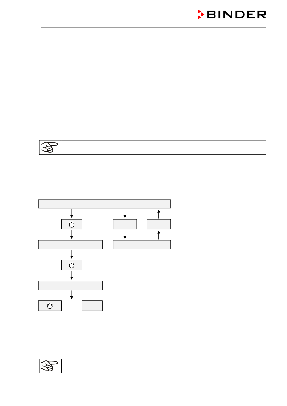
Structure of toggling between Idle Mode / Manual Mode / Program Mode:
Idle Mode
HAND
EXIT
Menu Program start Manual Mode (HAND)
Program Mode (AUTO)
or
EXIT
Heating up time
Average heating up time approx. 5 °C/min (the air flap closed and the fan set to maximum speed).
Cooling down time
Average cooling down time approx. 0.2 °C/min to 1.5 °C/min (the air flap open and the fan set to maxi-
mum speed).
If the chamber is fully loaded, the specified heating up and cooling down times may vary ac-
cording to the load.
M (E2) 04/2019 page 18/71
6. Controller MB1 settings
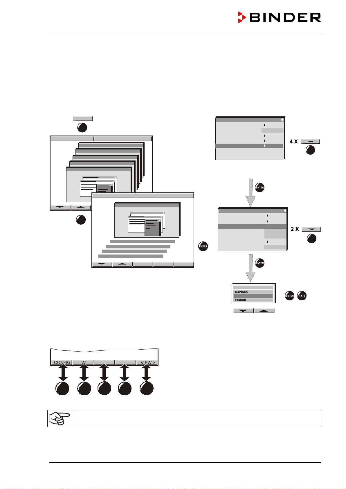
6.1 Selection of the menu language
The display program controller MB1 controls the temperature inside the chamber. The controller com-
municates by a menu guide using real words in German, English and French.
The selection of the desired menu language is located in the sub-menu “User-Level” of the “User-
Settings” menu. Select menu point “Language“.
User-Settings
08:43:55 15.12.13
Configuration 2
Configuration 1
Parameters
Choose variation
08:43:55 15.12.13
Configuration 2
Parameters
Choose variation
Configuration 1
User-Settings
CONFIG
4 X
User-settings
Instrument data
Contrast
Displ. Power down
Contin. operation
User Level
Safety control. Act + 36.8°C
Safety control. Set. 38.5
°C
29
User level code no. 1 (factory setting)
User Level
Date and time
Summer time
Language
Temperature unit
Buzzer
Safety controller
User-code No.
English
°C
1
Active
Sollwert Art
Offset
Language
English
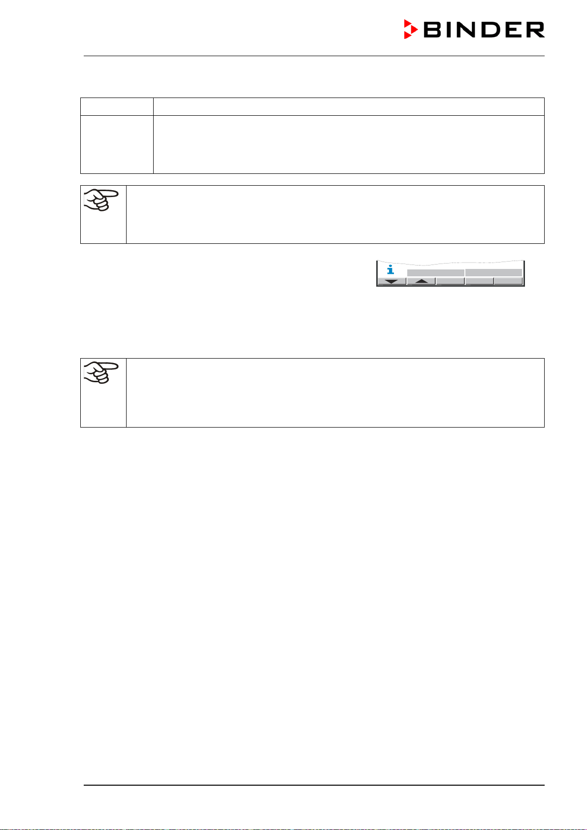
The row of buttons below the display is context-sensitive. The inscription above the buttons on the display
defines the button’s function.
Do NOT change the temperature unit from °C to °F.
M (E2) 04/2019 page 19/71
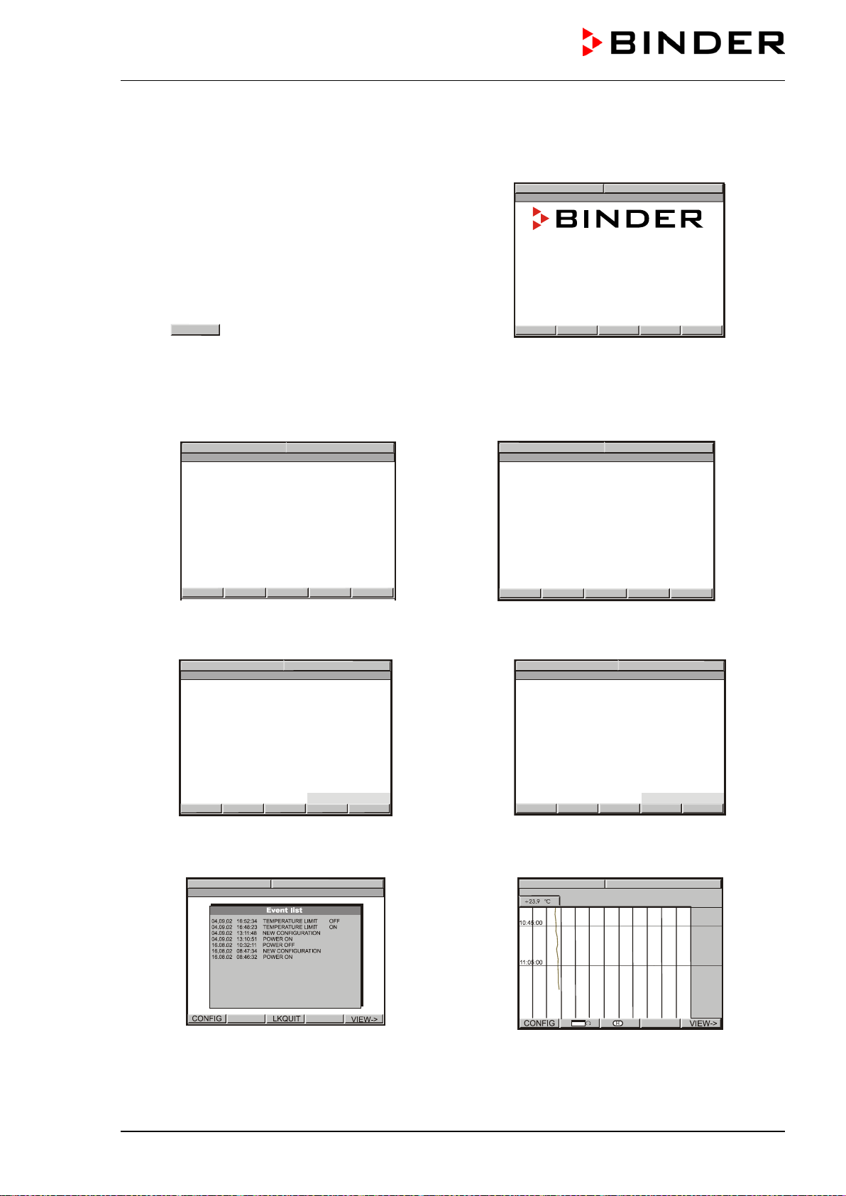
6.2 Overview of program controller MB1 displays
The main operation level contains the following
different displays:
• Normal display
(Idle Mode or Manual Mode or
Program Mode)
• Event List
• Chart recorder function
• Contact page
Button
VIEW ->
allows toggling between the dis-
plays.
The NORMAL DISPLAY enables comparison of the
current temperature (W) to the set-point value (X) or
shows the fan working rate.
CONTACT PAGE
BINDER Service contact display.
NORMAL DISPLAY Idle Mode
W
X
08:43:55 15.12.
13
CONFIG
VIEW->
PGM
TEMP
0.0
26.8
°C
HAND
or
W
X
08:43:55 15.12.13
CONFIG
VIEW->
PGM
FAN SPEED
50
%
HAND
No heating. The actual value (X) approximates ambient temperature. Fan operates at a 50% rate.
NORMAL DISPLAY Manual Mode
W
X
08:43:55 15.12.13
CONFIG
VIEW->
PGM
TEMP
40.0
36.8
°C
HAND
The temperature value is main
tained according to
the previous entered set-point (W).
NORMAL DISPLAY Program Mode
W
X
08:43:55 15.12.
13
PROGRAM 01/SEC1 00:09:59
CONFIG
HAND VIEW->
PGM
TEMP
40.0
36.8
°C
AUTO
A temperature program entered before via a pro-
gram table is run.
EVENT LIST
Overview over the last 16 events or error occur-
rences of the chamber.
CHART RECORDER FUNCTION
Graphical display of the current temperature val-
ues and review of the previous meas
urements on
a historical display. A memory interval of 5s corre-
sponds to a supervision period of 2.5 days.
08:43:55 15.12.13
Service Hotline
International: +49 7462 205 555
USA Toll Free: +1 866 885 9794
or +1 631 224 4340
: +7 495 988 1516
РоссияиСНГ
www.binder-world.com
CONFIG
VIEW-> VIEW->
Best conditions for your success
08:43:55 15.12.13
08:43:55 15.12.13
M (E2) 04/2019 page 20/71
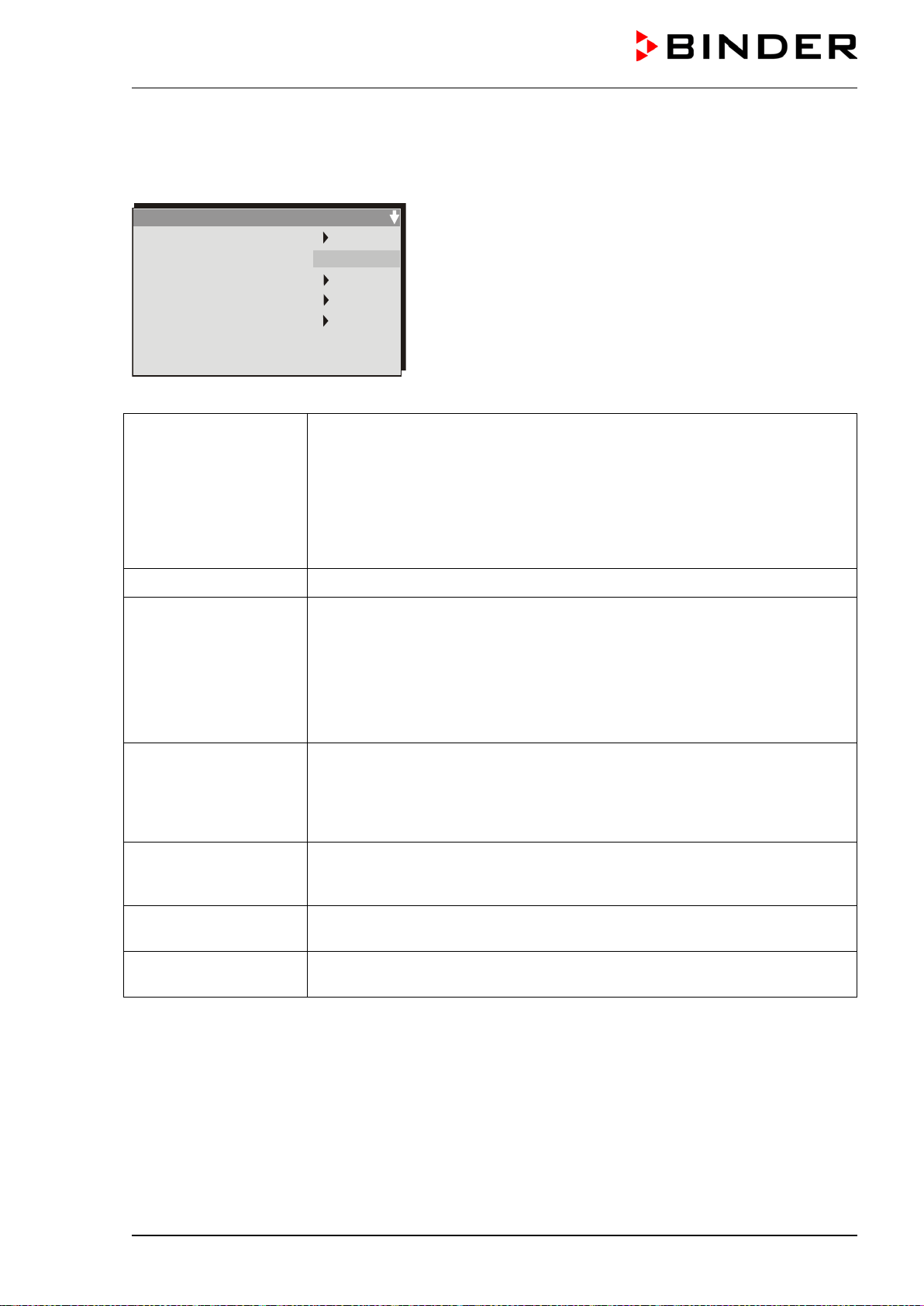
6.3 Menu settings in the “User-settings” menu
User
-settings
Instrument data
Contrast
Displ. Power down
Contin. operation
User Level
Safety control. Act + ****.* °C
Safety control. Set. + 0 °C
29
Instrument data Instrument Name
Enter an individual name of the constant climate chamber.
Address
Enter a controller address (1 to 30) for operation with the APT-COM™ 4 Multi
Management Software.
All other entries are relevant only for service purposes.
Contrast
(no function)
Displ. power down Switch off event
Do not change the entry “Wait. Period”.
Waiting period
You can enter a delay time after which the display, following manual activa-
tion, will automatically be turned off. This happens when the moment is out-
side the operation time defined in menu ”Contin. operation”.
Contin. operation
Enter an operation time to determine the period of display activity. Outside
the defined time, the display is automatically turned off. Pressing down any
key will reactivate the display. After the time set in menu “Displ. power down“,
the display will turn off again when the actual time is not within the operation
time fixed in menu “Cont. operation“.
User Level
Toggle here to the display menu “User Level” (chap. 6.4) by entering a pass-
word. Factory default setting for this password is +00001. You can change
the password (“user code”) in the menu “User Level”.
Safety control.Set
The safety controller is not used with the actual controller version. The dis-
plays are without function.
Safety control.Act
The safety controller is not used with the actual controller version. The dis-
plays are without function.
M (E2) 04/2019 page 21/71
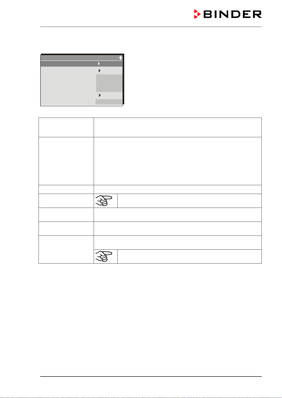
6.4 Menu settings in the “User Level” menu
User Level
Date and time
Summer time
Language
Temperature unit
Buzzer
Safety controller
User-code No.
English
°C
1
Active
Date and time
Enter the actual date and time to provide the proper measurement records.
Data is displayed in the chart recorder function (chap. 7) of the controller and
will remain stored in case of a power failure.
Summer time
Time is set one hour in advance during the summer time period.
Setting the summer time switch:
• Off: No change to summer time occurs
• User timed: Beginning and end of summer time can be set individually
• Automatic:
The summer time arrangement for central Europe is enabled
(summer time from last Sunday of March until last Sunday of October)
Language
Select the menu language as German, English, or French (chap. 6.1).
Temperature unit
Do NOT change the temperature unit from °C to °F.
Buzzer
The buzzer is not used with the actual controller version. The displays are
without function.
Safety controller
The safety controller is not used with the actual controller version. The dis-
plays are without function.
User-Code No.
Change the password (“user code”) needed to access the menu “User level”.
Factory default setting +00001.
Keep in mind any modification of the user password. There is no
access to this menu without the correct password.
M (E2) 04/2019 page 22/71
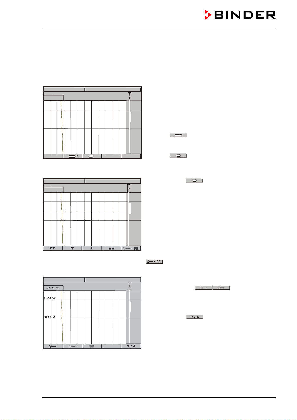
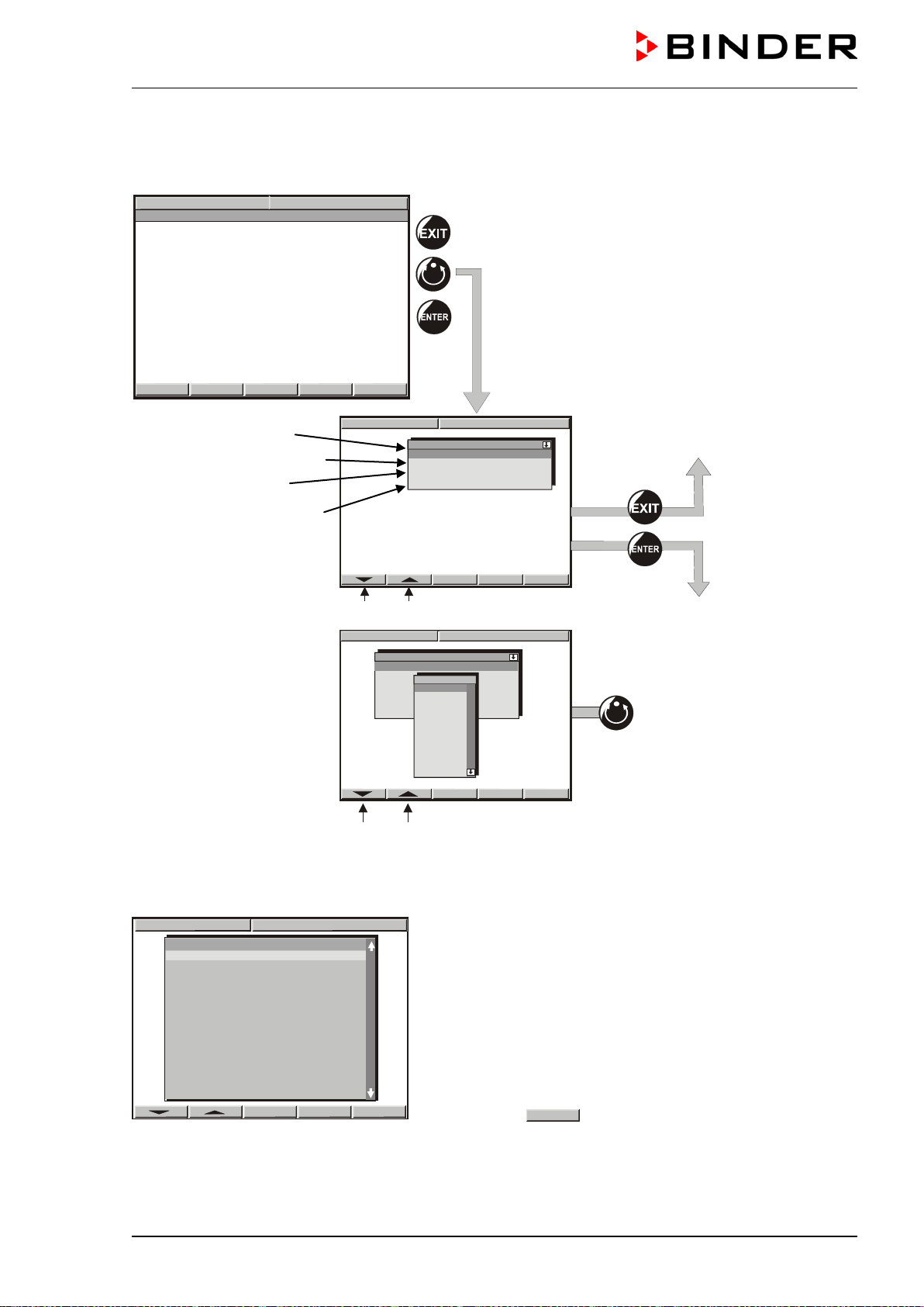
7. Graphic representation of the historical measurement (chart
recorder function)
The representation of data imitates a chart recorder and allows recalling any set of measured data at any
point of time taken from the recorded period.
Normal display of the chart recorder function:
Top left: The actual date and time are displayed.
Below: The current temperature value [ °C] is numeri-
cally and graphically displayed.
Scaling of temperature: 0 °C to 300 °C.
The open air flap is displayed on the right side as
a
thick line.
Button
allows toggling between different rep-
resentations.
Depending on the selected kind of represen
tation,
button
H
might not have been visible
until this
procedure.
History display with cursor:
Select button
H
= History. A pink line appears
on the display marking as a cursor the selected mo-
ment. You can now recall the recorded data of any
defined moment.
Top left: Date and time of the selected cursor position
are displayed.
Below: The corresponding temperature value of this
instance is numerically and graphically displayed.
Scroll the cursor position using the arrow buttons.
Single arrow buttons: fine-tuning.
Double arrow buttons: page-up and page-down.
Toggle to the zoom display by pressing button
:
History - zoom function:
Magnifier buttons
: Zoom and zoom
back (i.e., shorten or extend the displayed period).
Toggle back to the former representation display us-
ing this button
.
11:32:20 15.12.13
10:45:00
+23.9 °C
11:05.00
11:32:37 15.12.13
11:32:14 15.12.13
10:45:00
+23.9 °C
CONFIG
VIEW->
H
11:05:00
M (E2) 04/2019 page 23/71
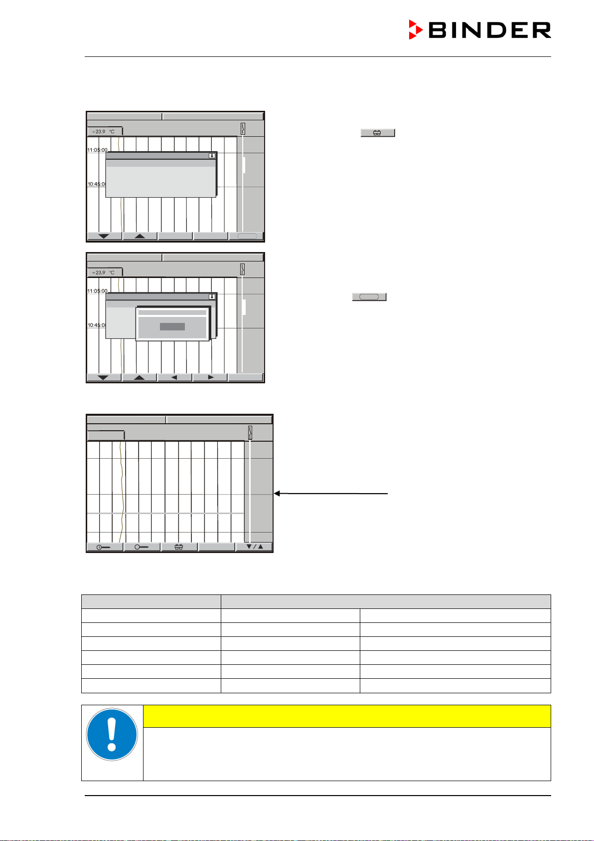
You can also directly enter any cursor position as a numerical input.
History representation: Toggling to any defined moment:
Press button
. The window “Cursor position”
opens to enter date and time.
Select date or time
with the arrow buttons and confirm
with ENTER.
Now you can access any moment that you would like to
recall. Enter date and time with the arrow buttons and
confirm with ENTER.
Press button
STA RT
.
History display at the selected point of time:
Top left: Date and time of the selected cursor position are
displayed.
Below: The corresponding temperature value of this mo-
ment is numerically and graphically displayed.
The cursor line marks the corresponding moment.
The available presentation depends on the pre-selected storage rate. This means the higher the storage
rate, the more precisely but shorter the data representation will be, see table below:
Storage rate
Storage duration
(hours)
(days)
5 sec
60
2.5
10 sec
120
5
1 min
720
30
5 min
3600
150
10 min
7200
300
CAUTION
Setting the storage rate clears the measured-value memory.
Danger of information loss.
Change the storage rate ONLY if the previously registered data is no longer needed.
Cursor
position
Date
Time
Grenzwert
Offset
Date
10.01.02
Offset
Datum
30.11.13
11:34:39 15.12.13
START
Cursor
position
Date 15.12.09
Time 11:34:27
11:34:27 15.12.13
20:30:00 30.11.13
20:00:00
+22.7 °C
21:00:00
19:00:00
M (E2) 04/2019 page 24/71
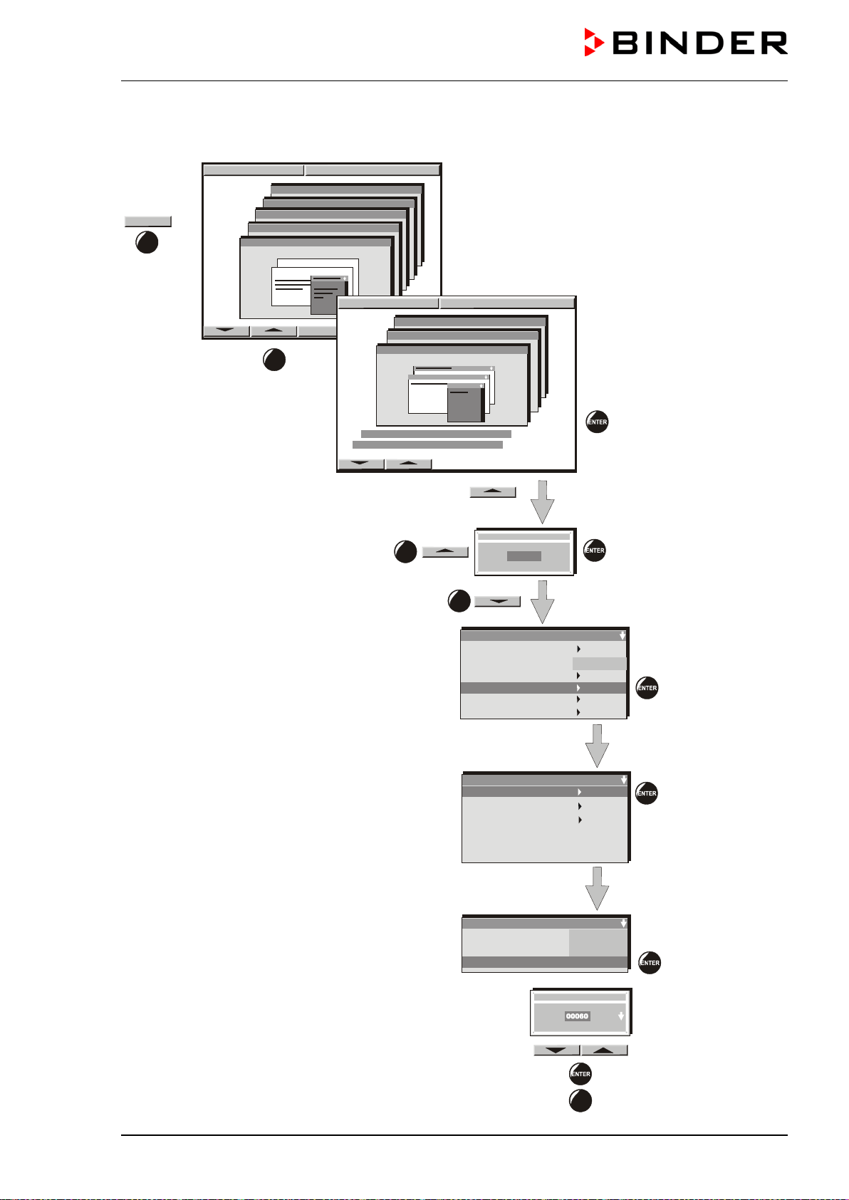
7.1 Setting the storage rate
Enter the storage rate with the arrow keys and
confirm by pressing “ENTER”.
To leave this menu press the “EXIT” button several
times.
Configuration 1
Diagram view
Feed view
Event tracks
Datalogging
Interface
Analog view
Time/div
Sollwert Art
Storage rate
EXIT
Datalogging
Normal operation
Event operation
Timed operation
Normal operation
Store status
Store value
s
Storage rate
Actual val.
60s
On
CONFIG
User-Settings
Configuration 2
Configuration 1
Parameters
Choose variation
Parameters
Choose variation
2 X
3 X
11:44:17 20.12.13
11:44:17 20.12.13
2 X
User-Settings
Configuration 2
Configuration 1
Grenzwert
Offset
User-Code ?
+00001
1 X
M (E2) 04/2019 page 25/71
8. Manual Mode
In Manual Mode (HAND) you can enter a temperature set-point, the fan speed (0% to 100%), and the
switching-state of up to 8 operation lines. Operation line 1 is used to control the air flap position. The oth-
er operation lines are non-functional. All settings remain valid in Manual Mode (HAND) until the next
manual change, if the chamber had been turned off or in case of toggling to Idle Mode or Program Mode
(AUTO).
8.1 Entering the set point values
W
X
CONFIG
HAND
PGM
VIEW->
08:43:55 15.12.13
CONFIG
CONFIG
CONFIG
FAN
50.0
%
Idle Mode
No heating function.
Fan working at 50% rate (factory set-
ting).
Toggling to Manual Mode
Change of page
Toggling between temperature set-point, fan speed, and operation lines.
Arrow buttons to select the operation
lines (Operation line 1 = air flap)
ON = air flap open
OFF = air flap closed
Arrow buttons
to enter the val-
ue
Button to move the decimal point
Unlock the keyboard locking (option, chap. 11.10) via the key switch to enter the set-point.
08:43:55 15.03.13
HAND
HAND
Hand-Mode
TEMP
SPEED
Steuerkontakte
+
29.3 °C
+80.0 %
Hand-Mode
TEMP
FAN SPEED
Operating contacts
+40.0 °C
+50.0 %
PGM
CONFIG
W
VIEW->
EXIT
08:43:55 15.12.13
HAND
08:43:55 15.12.13
Operating contacts
Contact 1
Contact 2
Contact 3
Contact 4
Contact 5
Contact 6
Contact 7
Contact 8
On
Off
Aus
Aus
Aus
Aus
Aus
Off
HAND
Contact 1
Off
On
Hand-Mode
TEMP
FAN
Oper
+40.0 °C
+80.0 %
TEMP
+0060.0
°C
EXIT
M (E2) 04/2019 page 26/71
Setting ranges:
Temperature
0 °C up to 300 °C
Fan speed
0 % to 100 %
Fan speed can be reduced to standstill of the fan. Do this only if needed, because the
spatial distribution of temperature will also be reduced. Technical data refer to 100%
fan speed.
Adapt the temperature safety device class 2 (chap. 10.1) or the temperature safety device
class 3.1 (option, chap. 10.2) every time the set-point for temperature is changed.
Set the set-point of temperature safety device class 2 or class 3.1 (option) by about 5 °C to 10
°C above the controller temperature set-point.
If operation line 1 has been set to ON, i.e., the air flap is open,
the notification “AIR FLAP OPEN” is displayed on the controller
MB1 display next to a flashing blue information symbol.
In Manual Mode, no program can be started. A set-point can be entered for temperature. The actual val-
ue equilibrates to this set-point.
When pushing the EXIT button in Manual Mode, the controller changes to Idle Mode. The set-points en-
tered in Manual Mode remain saved.
When incidentally pressing the EXIT or AUTOMATIC button during Manual Mode operation,
the controller will change to Idle Mode and thus will not adjust any longer to the program set-
points.
We recommend keyboard locking (available via BINDER INDIVIDUAL customized solutions,
see chap. 11.10.) during operation.
8.2 Performance after power failure in Manual Mode
In Manual Mode (HAND), all functions return exactly to the same status the chamber had before power
failure. The set-point is immediately resumed, the switching states of the operation lines are conserved.
No error message indicating that a power failure has taken place is displayed. However, the power failure
will appear in the event list.
9. Program operation
The 1-channel program controller MB1 permits programming temperature cycles. It offers 25 program
memory positions with 100 program sections each. The total cumulative number of program sections is
limited to 500. It is not possible to link several programs.
For each program section a temperature set-point, the fan speed (0% up to 100%), and the switching-
state of up to 8 operation lines can be entered. Operating line 1 is used to control the air flap position.
The other operation lines are non-functional.
Programming is possible directly by the keypad of the controller or graphically by the APT-COM™ 4 Multi
Management Software (option, chap. 11.1) specially developed by BINDER.
HAND
W
VIEW->
AIRFLAP OPEN
M (E2) 04/2019 page 27/71
9.1 Menu-based program entry
Displays showing the initial normal display in Idle Mode
W
X
08:43:55 15.12.13
CONFIG
VIEW->
PGM
TEMP
0.0
26.8
°C
HAND
W
X
08:43:55 15.12.
13
CONFIG
VIEW->
PGM
FAN SPEED
50
%
HAND
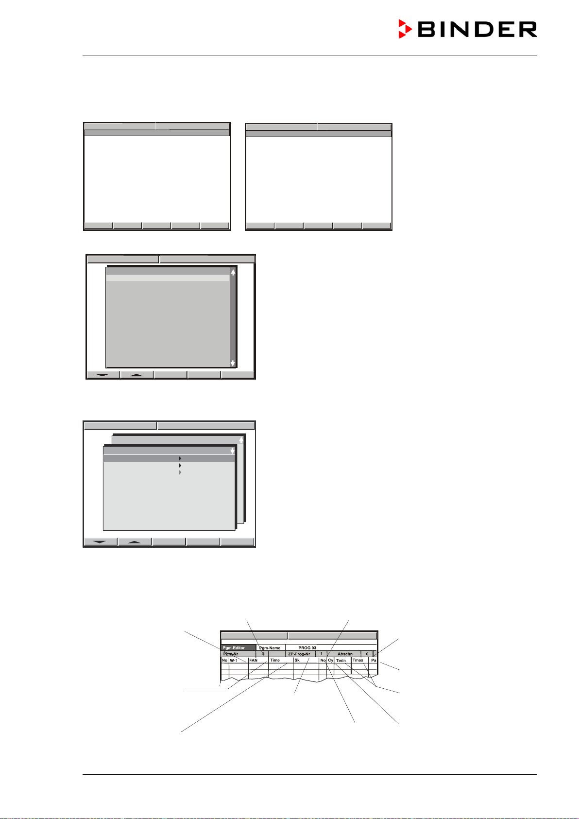
Hit button PGM. The window program selection appears
Select a program via the arrow keys and confirm by pressing “ENTER”
The following display serves to select a subroutine:
08:43:57 15.12.13
Prog. Select.
Prog 1 PROG 01
Prog 2 PROG 02
Prog 3 PROG 03
Prog 4 PROG 04
Prog 5 PROG 05
Prog 6 PROG 06
Prog 7 PROG 07
Prog 8 PROG 08
Prog 9 PROG 09
Prog 10 PROG 10
Prog 11 PROG 11
Prog 1 PROG 01
TP
-
Program 2
TP- Program 3
TP- Program 1
Select the first subroutine “TP-Program 1” (TP-Program 2 und TP-Program 3 are without function) and
confirm by pressing “ENTER”.
A program table will appear, which is initially empty until you enter the temperature values. You can now
enter the temperature program.
Temperature at the beginning
of the program section
Fan speed in %
Factory setting:
50% in Idle Mode
100 % in Manual Mode and
Program Mode
Program No.
Subprogram TP-Program No. 1
08:43:55 15.12.13
Total number of program
sections
Parameter set (preselected)
Tolerance band limits tem-
perature (maximum and min-
imum temperature)
Operation line 1
(air flap)
Duration of program
section
Number of start section in case
of repeat cycles
Number of duplicates in case
of repeat cycles
DEL PGM
08:43:55 15.12.13
Prog select Fr. Abs. 372
Prog 1 PROG 01
Prog 2
PROG 02
Prog 3
PROG 03
Prog 4
PROG 04
Prog 5
PROG 05
Prog 6
PROG 06
Prog 7
PROG 07
Prog 8
PROG 08
Prog 9
PROG 09
Prog10
PROG 10
Prog11
PROG 11
Prog12
PROG 12
Prog13
PROG 13
Prog14
PROG 14
Prog15
PROG 15
Prog16
PROG 16
Prog17 PROG 17
M (E2) 04/2019 page 28/71
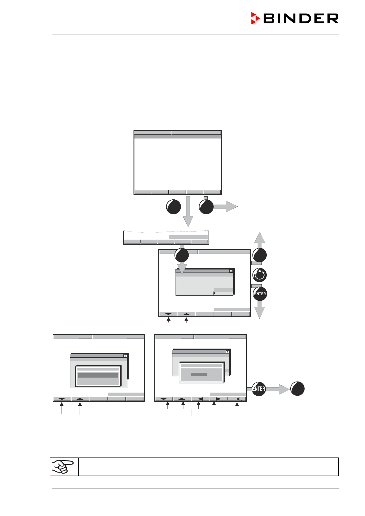
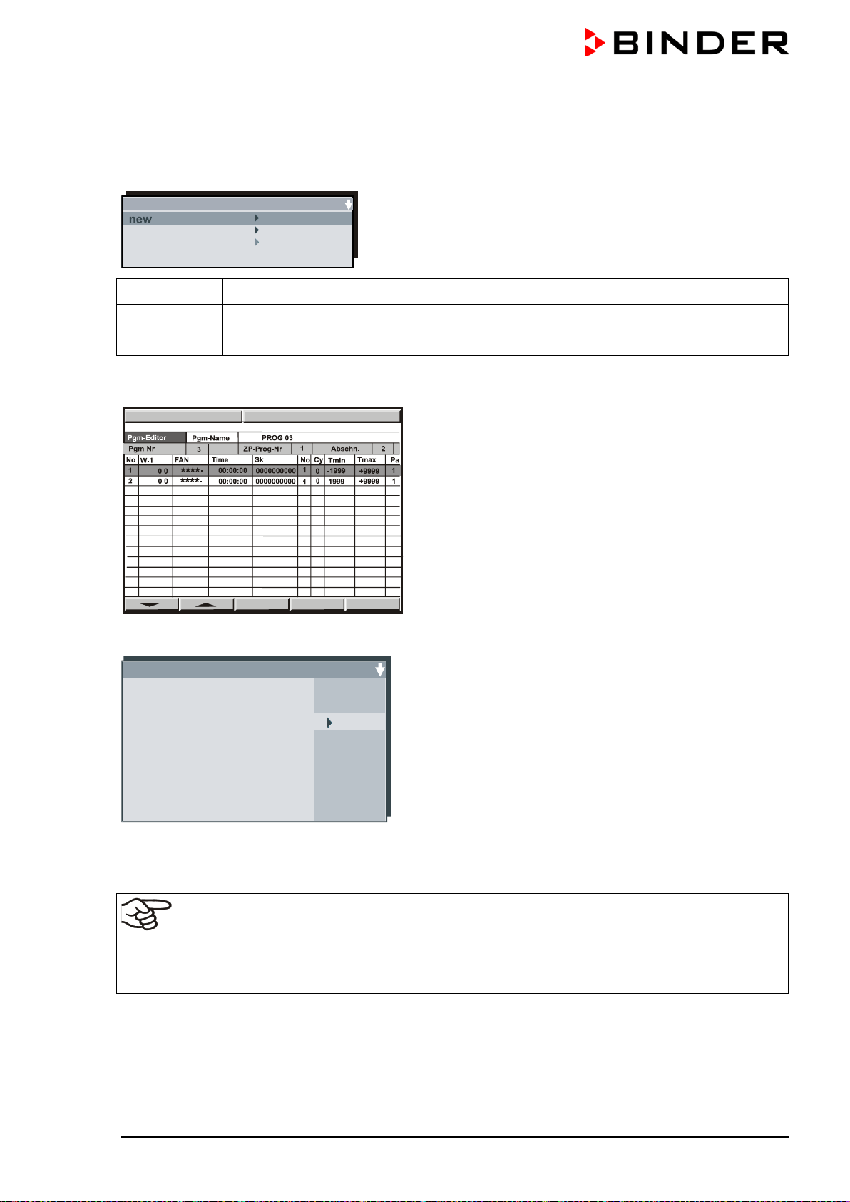
You can enter Program sections into this program table.
Hit the PGM button. An inquiry display appears allowing you to enter or delete individual program sec-
tions:
ZP-Abschnitt Abs. Nr. 5
insert
delete
In this view, new program lines can be entered or deleted:
new New lines are added below in the table
insert New lines are added above a previously selected line
delete Individual lines that have been selected previously are deleted
Create as many lines, i.e. program sections, as desired. As a next step, values can be entered into these
lines. It is possible to add supplementary lines later or to delete individual lines at any time.
To enter values, select the corresponding line via the
arrow keys.
Hit the “ENTER” button. The program editor ap-
pears.
Enter the individual values of the selected program section.
Program editor Abs.Nr. 6
****
.
*
Setpoint 1 +100.0
FAN
Operating contacts
Time 00:45:00
Repeat Section 5
Repeat Number 10
Tol.-band min. -1999.0
Tol.-band max. +9999.0
Parameter set 1
--
Temperature value at the start of the program section
-- Fan speed in %
-- Operating contact (operation line) 1 = air flap open / closed
-- Duration of the program section
-- No. of start section in case of repeat cycles
-- No. of duplicates in case of repeat cycles
-- Temperature limits (maximum / minimum temperature). In case
of exceeding: temporary program stop.
-- Pre-selected value (Do NOT change!)
Select the parameters via the arrow keys and confirm by pressing “ENTER”..
Then enter the values via the arrow keys, and confirm the entry by pressing “ENTER”..
Adapt the temperature safety device class 2 (chap. 10.1) or the temperature safety device
class 3.1 (option, chap. 10.2) to the highest temperature set-point value of the program actual-
ly used. Check the safety device for each temperature program and adapt it if necessary.
Set the set-point of temperature safety device class 2 or class 3.1 (option) by about 5 °C to 10
°C above the controller temperature set-point.
Performance after completing the program:
The controller changes to Idle Mode. The heating is inactive; the chamber approximates ambient temper-
ature. The fan turns at a 50% rate.
PGM
08:43:55 15.02.02
PGM
08:43:55 15.12.13
M (E2) 04/2019 page 29/71
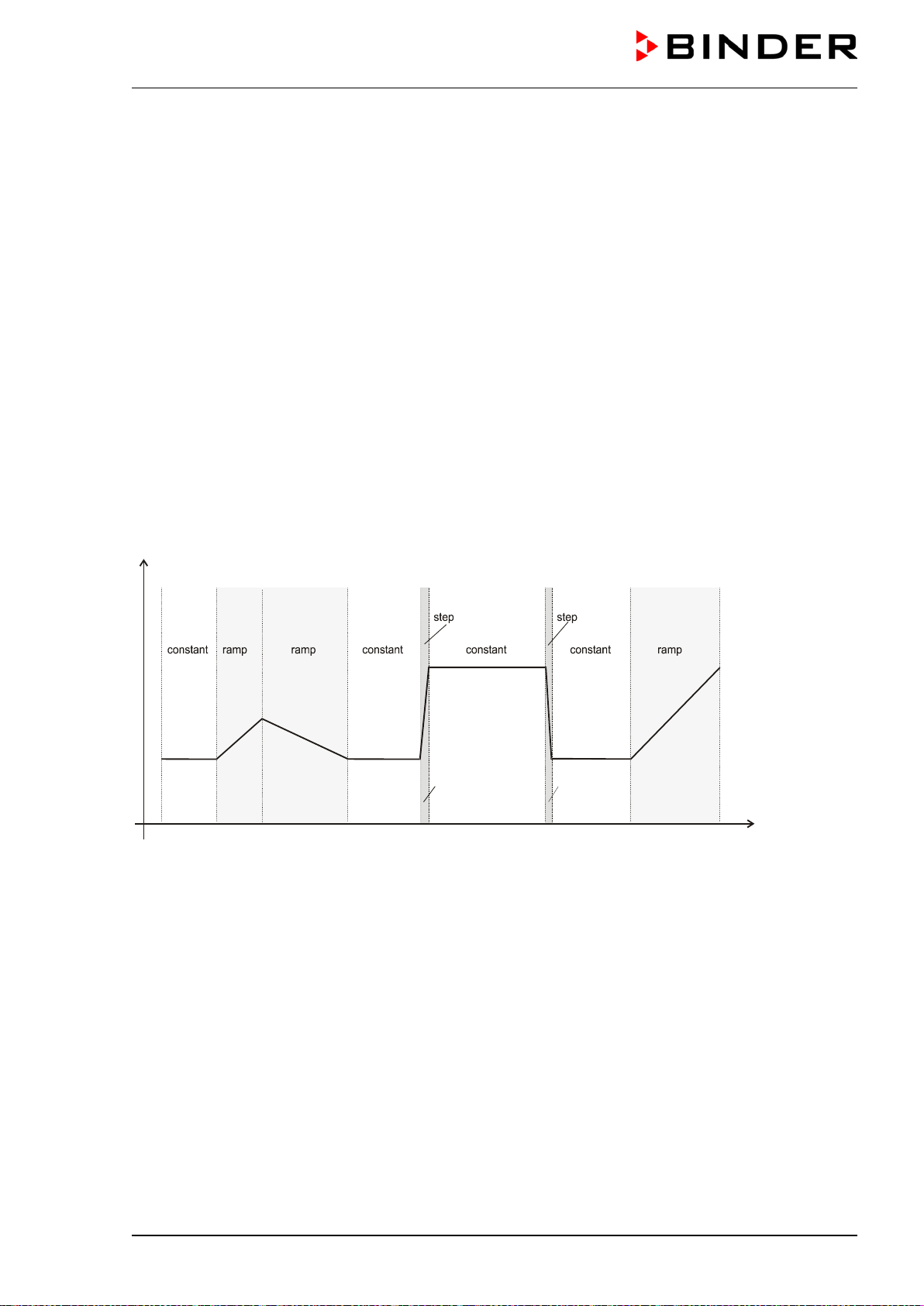
9.2 Selecting between set-point ramp and set-point step
Temperature set-points always refer to the start of a program section, i.e., at the beginning of each pro-
gram section the entered temperature set-point is targeted. During program section operation, the tem-
perature gradually passes to the set-point entered for the next program section.
By appropriate planning of the program section timing, you can enter all kinds of temperature transitions.
• Gradual temperature changes “set-point ramp”
The set-point changes its value gradually while proceeding from one program section to the next one
during the programmed section length. The actual temperature value (X) follows the continually mov-
ing set-point (W) at any time.
• Program sections with constant temperature
The initial values of two subsequent program sections are identical; so the temperature remains con-
stant during the whole time of the first program section.
• Sudden temperature changes “set-point step”
Steps are temperature changes (ramps) that occur during a very short interval. A section with a differ-
ent set-point follows two program sections with an identical set-point. If the duration of this transitional
program section is very short (minimum entry 1 sec), the temperature change will proceed rapidly
within the minimum amount of time.
01
02
03
04
05
06
07
08
09
W
t
Figure 7: Possible temperature transitions
The following chapter offers examples of programming a set-point ramp and a set-point step.
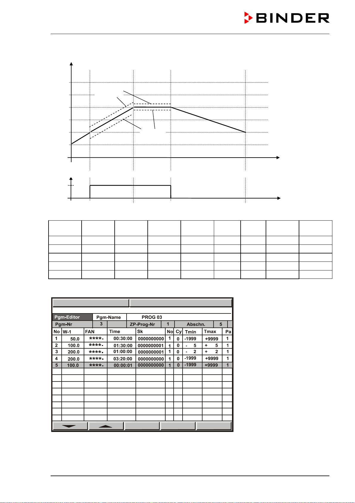
9.3 Program entry as set-point ramp or as set-point step
In order to avoid incorrect programming, we recommend plotting the temperature profile (chart template
in chap. 9.9) and entering the values into a table (templates in chap. 9.10).
The controller provides 8 operation lines that can be activated or de-activated for each program section.
Operating contact 1 is used to control the air flap position (ON = Air flap open, OFF = Air flap closed). The
other operation lines are non-functional.
The chamber does not provide active refrigeration, but you can program defined cooling down ramps
within the range of possible cooling-down times , e.g. in order to avoid tension in the material.
M (E2) 04/2019 page 30/71
Program entry as set-point ramp (example)
On
Off
t/min.
Operation line 1 = air flap
W/°C
t/min.
01
02
03
04
0
50
100
150
200
250
30
120
180
380
05
Tolerance
minimum
Tolerance
maximum
Program table corresponding to the diagram above:
Program
section
Set-point
temp.
Fan Section
time
Operation
line1
Target
section
No. of
cycles
Min.
tolerance
Max.
tolerance
01
50
100 %
00:30:00
Off
1
0
-1999
+9999
02
100
100 %
01:30:00
Off
1
0
-5
+5
03
200
100 %
01:00:00
Off
1
0
-2
+2
04
200
100 %
03:20:00
Off
1
0
-1999
+9999
05
100
100 %
00:00:01
Off
1
0
-1999
+9999
Now enter the values of the above program table into one of the 25 program places of the controller MB1:
PGM
08:43:55 15.02.02
PGM
08:43:55 15.12.13
M (E2) 04/2019 page 31/71
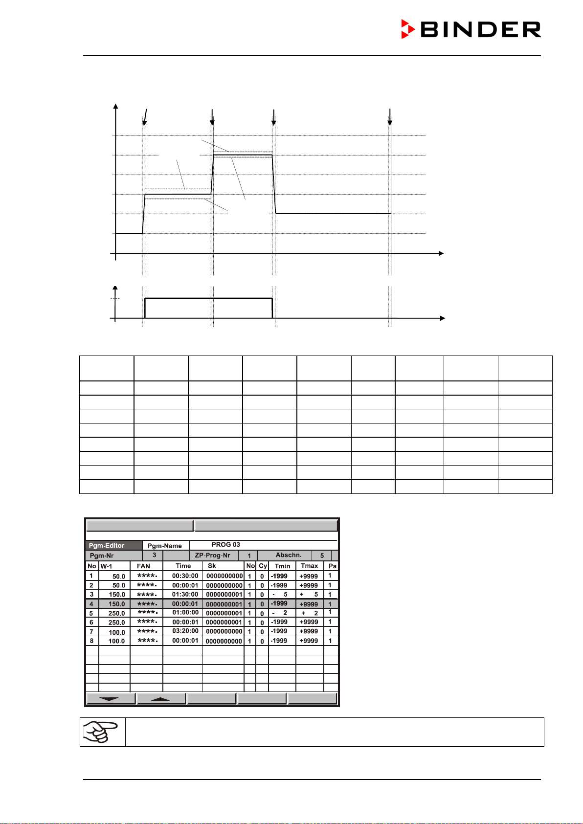
Program entry as set-point step (example)
W/°C
t/min.
01 02 03 04 05 06 07
08
0
50
100
150
200
25
0
30
120
180
380
Tolerance
minimum
Tolerance
maximum
On
Off
t/min.
Operation line 1 = air flap
Program table corresponding to the diagram above:
Program
section
Set-point
temp.
Fan
Section
time
Operation
line1
Target
section
No. of
cycles
Min.
tolerance
Max.
tolerance
01
50
100 %
00:30:00
Off
1
0
-1999
+9999
02
50
100 %
00:00:01
Off
1
0
-1999
+9999
03
150
100 %
01:30:00
On
1
0
-5
+5
04
150
100 %
00:00:01
On
1
0
-1999
+9999
05
250
100 %
01:00:00
On
1
0
-2
+2
06
250
100 %
00:00:01
On
1
0
-1999
+9999
07
100
100 %
03:20:00
Off
1
0
-1999
+9999
08
100
100 %
00:00:01
Off
1
0
-1999
+9999
Now enter the values of the above program table into one of the 25 program places of the controller MB1:
For rapid transition phases, do NOT program any tolerance limits in order to allow maximum
heating speed.
PGM
09:17:15 15.12.13
M (E2) 04/2019 page 32/71
9.4 Information on programming different temperature transitions
• For the end value of the desired cycle, add an additional section (in the examples section 05 for set-
point ramp and section 08 for set-point step) with a section time of at least one second. Otherwise, the
program will stop one section too early because the program line is incomplete.
• If the tolerance minimum is set to e.g. -5 and the tolerance maximum to e.g. +5, the program is inter-
rupted when the actual value deviates by 5 °C or more from the set-point value. During this program
interruption, the display reads at the right below AUTO HAND instead of AUTO (program operation).
You can enter different values for tolerance maximum and minimum for each section. When the tem-
perature is situated within the entered tolerance limits, the program is automatically continued. The in-
dication AUTOHAND disappears.
Programming of tolerances can extend program duration.
Therefore, the duration of the program might be extended due to the programming of tolerances.
The number -1999 for the tolerance minimum means “-∞“ and the number 9999 for the tolerance max-
imum means “+ ∞“. Entry of these numbers will never lead to program interruption.
During the rapid transition phase, do NOT program any tolerance limits in order to allow the maximum
heating speed.
• The initial setting ∗∗∗∗.∗ of the fan speed corresponds to the maximal speed of 100 %.
Do reduce the fan speed rate ONLY if it is absolutely necessary for the essay. Usually,
the spatial exactitude of the temperature decreases with lesser ventilation. Technical data
refers to a 100 % fan speed rate.
• Programming is stored even in case of power failure or after turning off the chamber.
• The controller memory can store a maximum of 25 programs. Each program cannot exceed 100 sec-
tions. It is not possible to link programs. The total number of program sections of all programs is lim-
ited to a maximum of 500.
If you incidentally press the EXIT or AUTOMATIC button during program operation, the control-
ler will change to Idle Mode and thus will not adjust any more to the program set-points.
We recommend keyboard locking (available via BINDER INDIVIDUAL customized solutions,
see chap. 11.10.) during operation.
General note:
The controller MB1 displays more menu entries than those described in this manual. These are password
protected because they are relevant for service purposes only and the user must not modify them. Only
service authorized by BINDER can access these entries.
M (E2) 04/2019 page 33/71
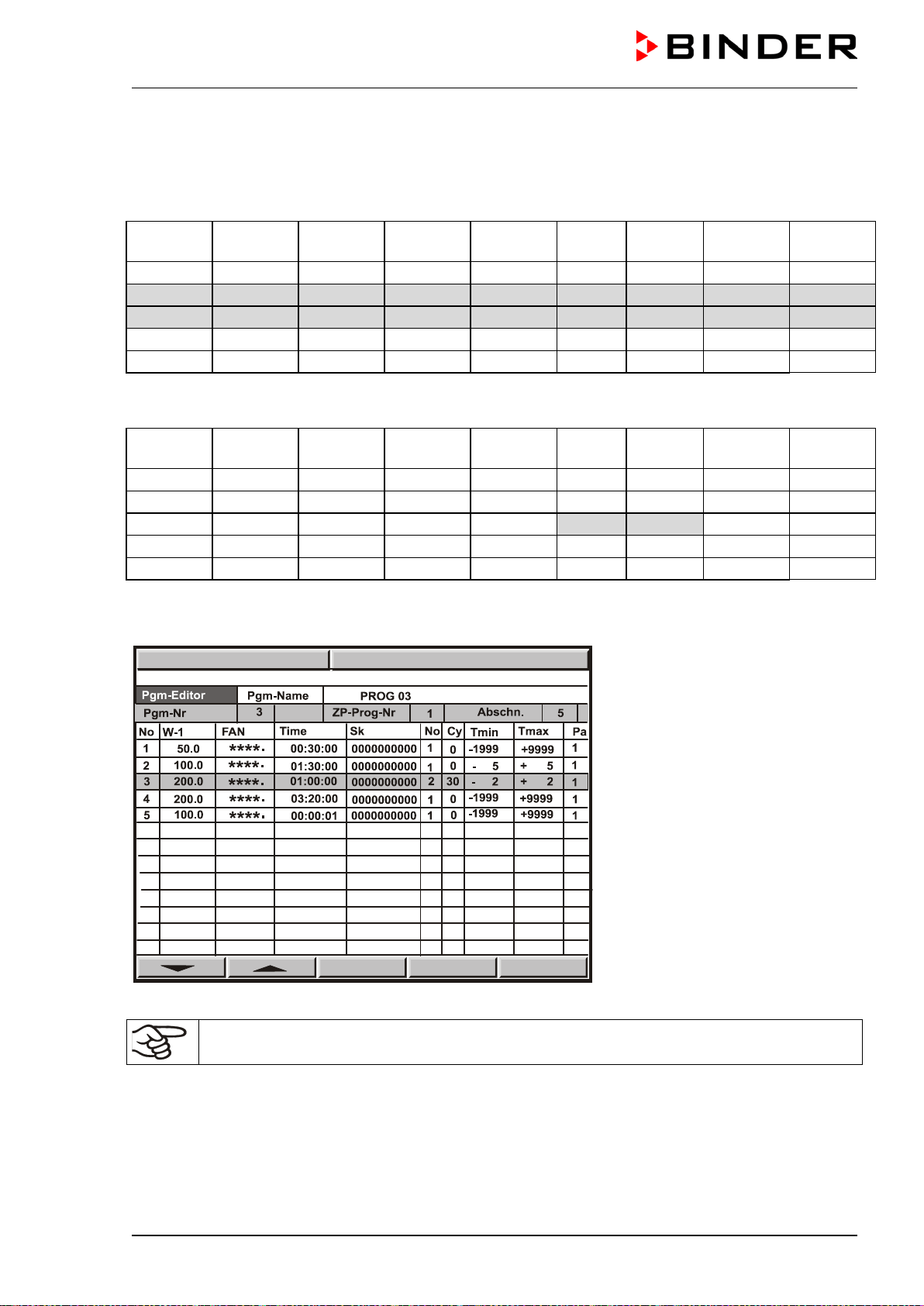
9.5 Repetition of a section or several sections within a program
Here we use the example of a set-point ramp temperature program of chap. 9.3. The shaded sections 02
and 03 shall be repeated e.g. 30 times.
Program
section
Set-point
temp.
Fan
Section
time
Operation
line1
Target
section
No. of
cycles
Min.
tolerance
Max.
tolerance
01
50
100 %
00:30:00
Off
1
0
-1999
+9999
02
100
100 %
01:30:00
Off
1
0
-5
+5
03
200
100 %
01:00:00
Off
1
0
-2
+2
04
200
100 %
03:20:00
Off
1
0
-1999
+9999
05
100
100 %
00:00:01
Off
1
0
-1999
+9999
The following table shows the program that results, whereby the differences to the table above are shad-
ed.
Program
section
Set-point
temp.
Fan Section
time
Operation
line1
Target
section
No. of
cycles
Min.
tolerance
Max.
tolerance
01
50
100 %
00:30:00
Off
1
0
-1999
+9999
02
100
100 %
01:30:00
Off
1
0
-5
+5
03
200
100 %
01:00:00
Off
2
30
-2
+2
04
200
100 %
03:20:00
Off
1
0
-1999
+9999
05
100
100 %
00:00:01
Off
1
0
-1999
+9999
Sections 02 and 03 will be executed in total 31 times; only then will the program continue.
Entry of the values into the display program table:
To have sections repeated infinitely, enter the number of cycles “Cy” as -1.
9.6 Performance after power failure in Program Mode
The program is resumed at the point where the interruption occurred with the latest set-points reached
during the program run. The power failure is noted in the event list. No error message is displayed indi-
cating that a power failure had taken place.
PGM
08:49:07 15.12.13
M (E2) 04/2019 page 34/71
9.7 Starting a previously entered program
The program has to be previously entered via a programming table (chap. 9.3).
Idle mode
No heating function.
Fan working at 50% rate
(factory setting)
Select a program place
Delayed program start
Start with section …
Remaining time of the se-
lected start section
Arrow buttons to select the parameter to be set
Press the “AUTOMATIC”
button to start the pro-
gram
Arrow buttons to select the program
9.8 Deleting a program
Select a program via the arrow keys
Hit button
DEL PGM
to delete the selected program.
To delete individual program sections (table lines) use the inquiry display for adding or deleting program
sections (chap. 9.1).
089:12:13 15.12.13
Program start
Program Prog 01
Pre start time 00:00:00
Section 1
Res time 00:00:00
Programm
PROG 01
PROG 02
PROG 03
PROG 04
PROG 05
PROG 06
PROG 07
PROG 08
PROG 09
PROG 10
PROG 11
PROG 12
PROG 13
PROG 14
W
X
09:11:55 15.12.13
CONFIG
VIEW->
PGM
TEMP
0.0
26.8
°C
HAND
09:12:02 15.12.13
Program start
Program Prog 01
Pre start time 00:00:00
Section 1
Rest time 00:00:00
DEL PGM
09:13:47 15.12.13
Prog. Select. Fr. Abs. 372
Prog 1 PROG 01 ►
Prog 2
PROG 02 ►
Prog 3
PROG 03 ►
Prog 4
PROG 04 ►
Prog 5
PROG 05 ►
Prog 6
PROG 06 ►
Prog 7
PROG 07 ►
Prog 8
PROG 08 ►
Prog 9
PROG 09 ►
Prog10
PROG 10 ►
Prog11
PROG 11 ►
Prog12
PROG 12 ►
Prog13
PROG 13 ►
Prog14
PROG 14 ►
Prog15
PROG 15 ►
Prog16
PROG 16 ►
Prog17
PROG 17 ►
Prog18
PROG 18 ►
Prog19
PROG 19 ►
P 20 PROG 20
M (E2) 04/2019 page 35/71
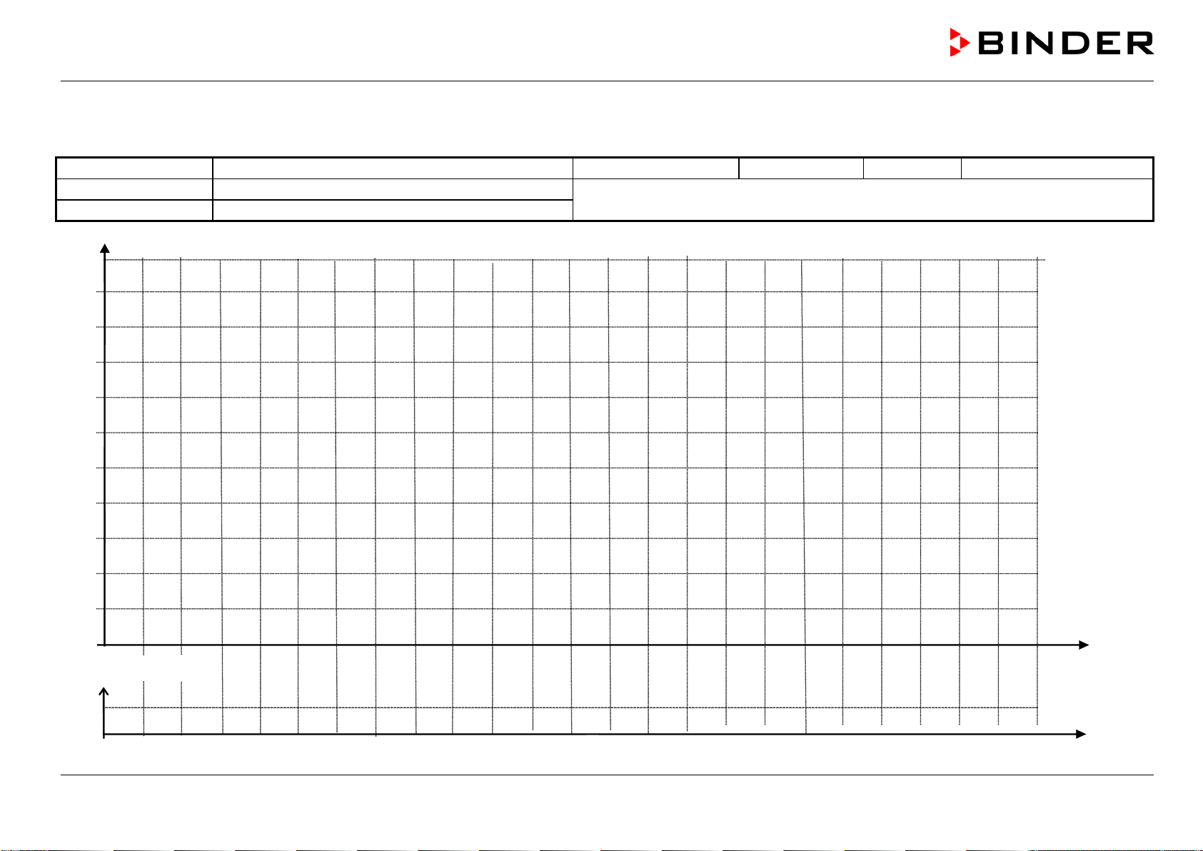
9.9 Temperature profile template
Programmer:
Program No. (1 to 25):
Date:
Program title:
Operation line 1 = Position of air flap
Project:
ON = open, OFF = closed
Time
-20
0
20
40
60
80
100
120
140
160
°C
Off
On
Air flap
-40
180
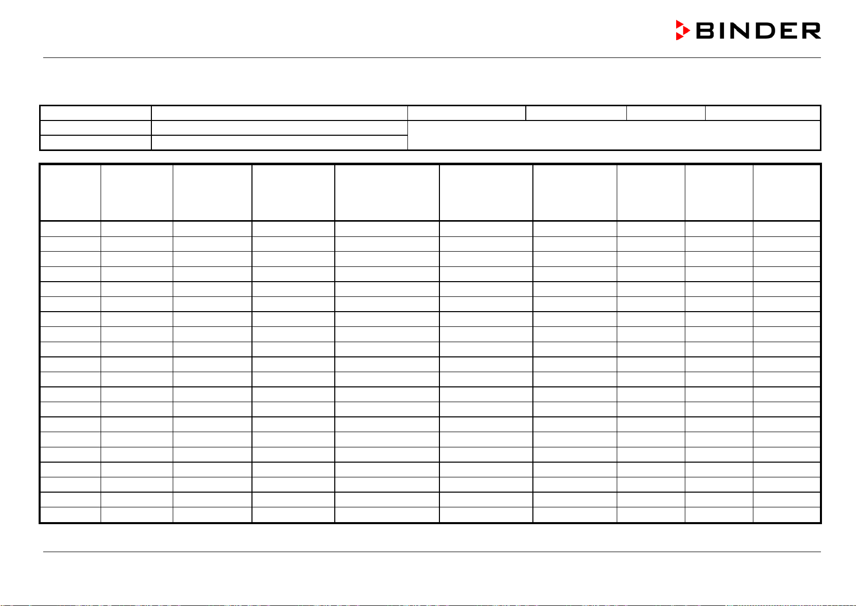
M (E2) 04/2019 page 36/71
9.10 Program table template
Programmer:
Program No. (1 to 25):
Date:
Program title:
Operation line 1 = Position of air flap
Project:
ON = open, OFF = closed
Section
No.
Set-point
Temperature
W-1
Fan speed
[%]
FAN
Section time
Time
Operation line 1
Sk
Start section for
repeat cycles
No
Number of re-
peat cycles
Cy
Tolerance
minimum
Temperature
Tmin
Tolerance
maximum
Temperature
Tmax
Parameter
set
Pa
01
1
02
1
03
1
04
1
05
1
06
1
07
1
08
1
09
1
10
1
11
1
12
1
13
1
14
1
15
1
16
1
17
1
18
1
19
1
20
1
Default setting
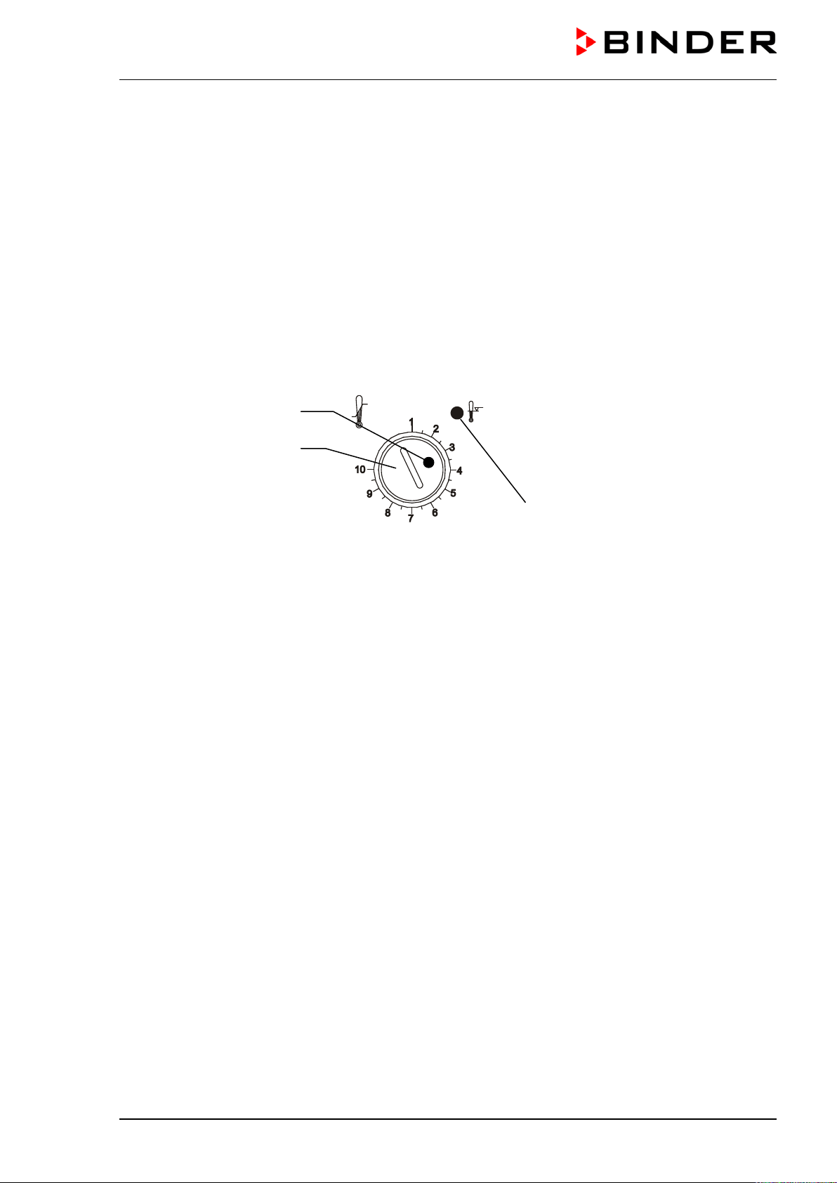
M (E2) 04/2019 page 37/71
10. Temperature safety devices
10.1 Temperature safety device class 2 (DIN 12880)
The temperature safety device class 2 acc. to DIN 12880:2007 protects the chamber, its environment and
the charging material from exceeding the maximum permissible temperature.
Please observe the DGUV guidelines 213-850 on safe working in laboratories (formerly BGI/GUV-I 850-
0, BGR/GUV-R 120 or ZH 1/119, issued by the employers’ liability insurance association) (for Germany).
In the event of a fault in the temperature controller, the safety device (3) permanently turns off the
chamber. This status is reported visually by the indicator lamp (3a).
Check the operation of the safety device (3) by moving it slowly counter-clockwise until the chamber turns
off. The safety device cut-off is reported visually by the indicator lamp (3a).
Then release again the safety device by pressing the reset button (3b), and turn on the chamber as de-
scribed.
Figure 8: Temperature safety device class 2
Function:
The safety device class 2 is functionally and electrically independent of the temperature control device
and turns off the chamber permanently.
If you turn the control knob (3) to its end-stop (position 10), the safety device protects the appliance. If
you set it to a temperature a little above the controller’s set-point temperature, it protects the charging
material.
If the safety device has turned off the chamber, identifiable by the red alarm lamp (3a) lighting up, pro-
ceed as follows:
• Disconnect the chamber from the power supply.
• Have an expert examine and rectify the cause of the fault.
• Release the safety device by pressing the reset button (3b).
• Restart the chamber as described in chap. 5.
Setting:
To check the response temperature of the safety device, turn on the chamber and set the desired set-
point at the temperature controller.
The sections of the scale from 1 to 10 corresponds to the temperature range from 30 °C / 86 °F up to 320
°C / 608 °F and serves as a setting aid.
• Turn the control knob (3) of the safety device using a coin to its end-stop (position 10) (chamber pro-
tection).
• When the set-point is reached, turn back the control knob (3) until its trip point (turn it counter-
clockwise)
• The trip point is identifiable by the red alarm lamp (3a) lighting up; the reset button (3b) pops out.
• The optimum setting of the safety device is obtained by turning the control knob clockwise by approx.
one graduation mark on the scale.
• Push the reset button (3b) in again.
(3)
(3a)
(3b)
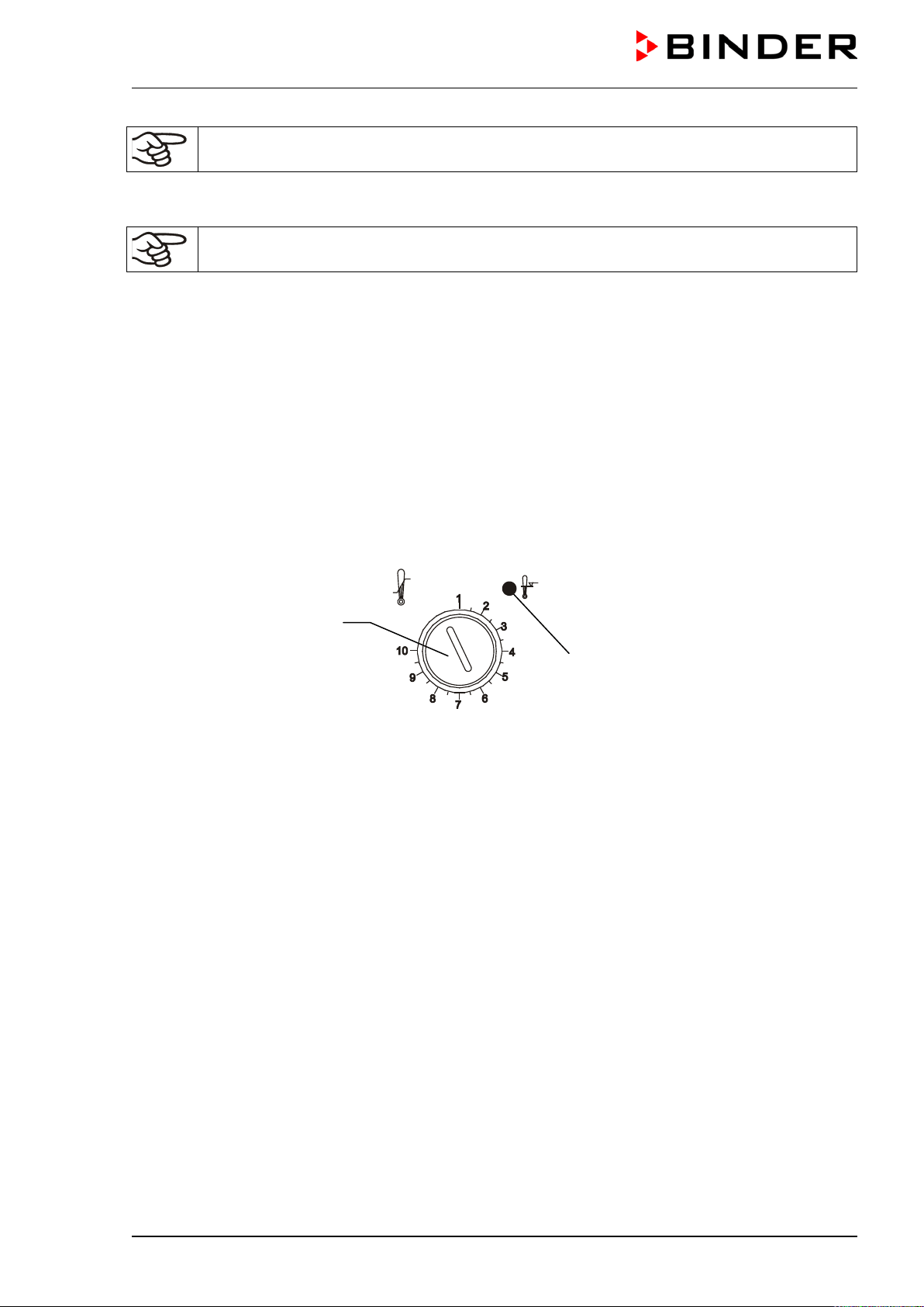
M (E2) 04/2019 page 38/71
The chamber is only active with the reset button (3b) pushed in.
When the safety device class 2 responds, the red alarm lamp (3a) illuminates, the reset button (3b) pops
out, and the chamber turns off permanently.
Check the setting regularly and adjust it following any changes of the set-point.
Function check:
Check the temperature safety device class 2 at appropriate intervals for its functionality. It is recommend-
ed that the authorized operating personnel should perform such a check, e.g., before starting a longer
work procedure.
10.2 Temperature safety device class 3.1 (DIN 12880) (available via BINDER
INDIVIDUAL customized solutions)
The temperature safety device class 3.1 acc. to DIN 12880:2007 protects the chamber, its environment
and the charging material from exceeding the maximum permissible temperature. In the event of a fault, it
limits the temperature inside the chamber to the value set on the safety device.
Please observe the DGUV guidelines 213-850 on safe working in laboratories (formerly BGI/GUV-I 850-
0, BGR/GUV-R 120 or ZH 1/119, issued by the employers’ liability insurance association) (for Germany).
Figure 9: Temperature safety device class 3.1
Function:
The temperature safety device is functionally and electrically independent of the temperature control sys-
tem and if an error occurs it performs a regulatory function.
If you turn the control knob (3) to its end-stop (position 10), the safety device class 3.1 protects the
chamber. If you set it to a temperature a little above the controller’s set-point temperature, it protects the
charging material. If the safety device class 3.1 has taken over control, identifiable by the red alarm lamp
(3a) lighting up, proceed as follows:
• Disconnect the chamber from the power supply.
• Have an expert examine and rectify the cause of the fault.
• Restart the chamber as described in chap. 5.
Setting:
To check the response temperature of the safety device class 3.1, turn on the chamber and set the de-
sired set-point at the temperature controller.
The sections of the scale from 1 to 10 correspond to the temperature range from 63 °C / 145.4 °F up to
350 °C / 662 °F and serve as a setting aid.
(3)
(3a)

M (E2) 04/2019 page 39/71
• Turn the control knob (3) of the safety device using a coin to its end-stop
(position 10) (chamber protection).
• When the set point is reached, turn back the control knob (3
) until its trip
point (turn it counter-clockwise).
• The trip point is identifiable by the red alarm lamp (3a).
• The optimum setting of
the safety device is obtained by turning the control
knob clockwise by approx. one scale division, which leads to extin
guish the
red alarm lamp (3a).
Figure 10: Setting safety device class 3.1
Check the setting regularly and adjust it following any changes of the set-point.
Function check:
Check the temperature safety device class 3.1 at appropriate intervals for its functionality. It is recom-
mended that the authorized operating personnel should perform such a check, e.g., before starting a
longer work procedure.
11. Options
11.1 APT-COM™ 4 Multi Management Software (option)
The chamber is regularly equipped with a serial interface RS 422 that can connect the BINDER APT-
COM™ 4 Multi Management Software. The actual temperature value is given at adjustable intervals.
Programming can be performed graphically via PC. Up to 100 chambers can be cross-linked. For further
information, refer to the APT-COM™ 4 operating manual.
Pin allocation of the RS 422 interface:
pin 2: RxD (+)
pin 3: TxD (+)
pin 4: RxD (-)
pin 5: TxD (-)
pin 7: Ground
11.2 Ethernet interface
With this option, the chamber is equipped with an Ethernet interface that can connect the BINDER APT-
COM™ 4 Multi Management Software. The actual temperature and humidity values are given at adjusta-
ble intervals. The MAC Address is indicated below the Ethernet interface. For further information, please
refer to the operating manual of the BINDER communication software APT-COM™ 3.
With this option, the additional RS422 interface is only used for service purposes. Do NOT connect it to
any network. The interface is labeled accordingly.
11.3 HEPA fresh air filter (option)
With this option, the introduced fresh air is cleaned by means of a high efficiency submicron particulate
air filter type HEPA class H 14 (acc. to DIN EN 1822:2009). Replace the filter insert, if necessary, by re-
moving the metal cover of the filter at the left side of the chamber (Art. No. 6014-0003).
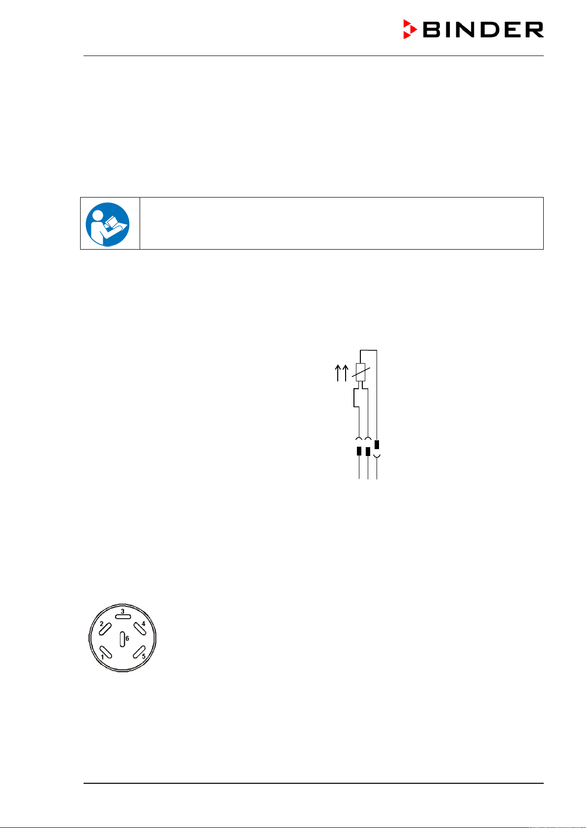
M (E2) 04/2019 page 40/71
11.4 Data logger kit (option)
BINDER Data Logger Kits offer an independent long-term measuring system for temperature. They are
equipped with a keyboard and a large LCD display, alarm functions and a real-time function. Measure-
ment data are recorded in the Data Logger and can be read out after the measurement via the RS232
interface of the Data Logger. It offers a programmable measuring interval and permits storing up to 64000
measuring values. Reading out is done with the Data Logger evaluation software. You can give out a
combined alarm and status protocol directly to a serial printer.
Data Logger Kit T 350: Temperature range 0 °C / 32 °F up to +350 °C / 662 °F
For detailed information on installation and operation of the BINDER Data Logger, please
refer to the mounting instructions Art. No. 7001-0204 and to the original user manual of the
manufacturer, supplied with the data logger.
11.5 Additional flexible Pt100-temperature sensor (option)
With this option, an additional flexible temperature sensor Pt 100 allows measuring the chamber tem-
perature or the temperature of the charging material by means of an independent measuring system with
Pt 100 entry. The sensor top protective tube of the flexible Pt 100 can be immersed into liquid substanc-
es.
Technical data of the Pt 100 sensor:
• Three-wire technique
• Class B (DIN EN 60751)
• Temperature range up to 320 °C
• Stainless steel protective tube 45 mm length
material no. 1.4501
Lemo socket
Lemo plug
Figure 11: Option temperature sensor Pt 100
11.6 Analog output for temperature (option)
With this option chamber is equipped with an analogue output 4-20 mA for temperature. This output al-
lows transmitting data to external data registration systems or devices.
The connection is realized as a DIN socket on the rear of the chamber as follows:
ANALOG OUTPUT 4-20 mA DC
PIN 1: Temperature –
PIN 2: Temperature +
Temperature range: 0 °C / 32 °F up to 300 °C / 572 °F
A suitable DIN plug is enclosed.
Figure 12: DIN socket for option analog output
1 2 3
1 2 3
2 3
1
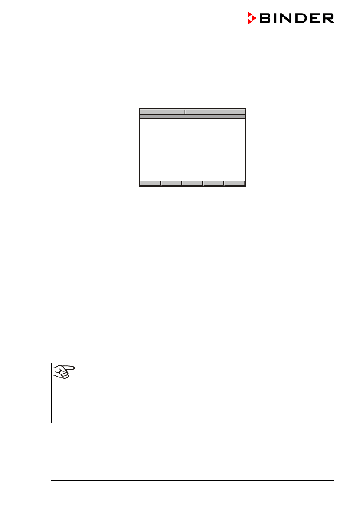
M (E2) 04/2019 page 41/71
11.7 Additional measuring channel for digital object temperature indicator with
flexible temperature sensor Pt 100 (option)
The object temperature display enables the determination of the actual temperature of the charging mate-
rial during the whole process. The object temperature is measured via a flexible Pt100 temperature sen-
sor and can be viewed at the display controller MB1. The sensor top protective tube of the flexible Pt 100
can be immersed into liquid substances.
W
X
CONFIG
HAND
PGM
VIEW->
09:12:24 15.12.13
TEMP
0.0
25.3
°C
OBJ-T
25.6
°C
Figure 13: Display controller MB1 with object temperature display
The object temperature data are put out together with the data of the temperature controller to the RS
422 interface as second measuring channel and can be documented by the APT-COM™ 4 Multi Mana-
gement Software (option, chap. 11.1) developed by BINDER.
Technical data of the Pt 100 sensor:
• Three-wire technique
• Class B (DIN EN 60751)
• Temperature range up to 320 °C / 608 °F
• Stainless steel protective tube 45 mm length, material no. 1.4501
11.8 Mostly gas-tight version (option for M 53 and M 115)
With this option the chamber is additionally sealed, so the loss when introducing gases is decreased. The
chamber is not completely gas-tight, so it is impossible to establish overpressure. The sealing diminishes
the release of vapors via the housing that may be set free from the charging material when heated. Carry-
ing-off via the regular evacuation duct, e.g. into a waste air installation, is likely to further reduce emis-
sions.
The chamber is not completely gas-tight. Gases from inside the chamber can escape into the
surrounding atmosphere.
Observe the occupational exposure limit OEL for the released substance set by the national
authorities (formerly maximum permitted workplace concentration). Respect the relevant
regulations.
Any harmful gas that might escape has to be led out via good room ventilation or a suitable
exhaust system. Place the chamber, if necessary, below a gas vent.
The air flap does not close the exhaust duct completely. The delivered plug serves to avoid emerging of
vapors or loss of introduced inert gas, if any, via the exhaust duct. Due to special demands of heat re-
sistance, use the delivered plug only.
M (E2) 04/2019 page 42/71
CAUTION
Use of inappropriate plug.
Danger of inflammation.
Use only the supplied plug to close the exhaust duct.
For drying purpose, please remove the plug in order to permit dissipation of the generated vapor, which
would lead to condensation in the inner chamber.
11.9 Inert gas connection with mostly gas-tight version (option for M 53 and M
115)
With this option the chamber is additionally sealed, so the loss when introducing inert gases is de-
creased. For details on the mostly gas-tight version please refer to chap. 11.8).
The chamber is equipped with two ports for inert gas (nitrogen or noble gases).
The ports are located on the top panel in the middle and on the right side at the bottom right. Each
of these ports can be used as inlet or outlet, depending on the nature of the inert gas:
• lighter gas (nitrogen, helium): lower port as inlet
• heavy gas (e.g. argon): upper port as inlet
Connection
Observe the legal requirements and relevant standards and regulations for the safe handling of gas cyl-
inders and inert gases.
General information for safe handling of gas cylinders:
• Store and use gas cylinders only in well ventilated areas.
• Open the gas cylinder valve slowly to avoid pressure surges
• Secure gas cylinders during storage and use against falling (chaining).
• Transport gas cylinders with a cylinder cart, do not carry, roll, or throw them
•
Always close the valve even with apparently empty cylinders; screw on the cap when not in
use. Return gas cylinders with the valve closed
• Do not open gas cylinders by force. Mark them when damaged
• Observe relevant regulations for dealing with gas cylinders.
Connect a flexible gas tube to the gas hose connection adapter (diameter 10mm), which is used for gas
inlet, and secure it with hose clamps (hose and hose clamps are not enclosed). There is a constant gas
flow after establishing the connection.
After connecting the gas cylinder, check all gas connections for leaks (e.g. with leak spray or
diluted soap solution).
Use a pressure reducer and make sure to avoid any excessive outlet pressure when connecting the gas
hose to the chamber.
The chamber is not completely gas-tight. Inert gases from inside the chamber can escape into
the surrounding atmosphere.
M (E2) 04/2019 page 43/71
Inert gases in high concentrations is hazardous to health. They are colorless and almost odorless and
therefore practically imperceptible. Inhalation of inert gases can cause drowsiness up to respiratory ar-
rest. When the O
2
content of the air decreases below 18%, there is risk of death from lack of oxygen. Any
gas that might escape has to be led out via good room ventilation or a suitable exhaust system.
WARNING
High concentration of inert gas.
Risk of death by suffocation.
Do NOT set up chambers in non-ventilated recesses.
Ensure technical ventilation measures.
Respect the relevant regulations for handling these gases.
Inert gases, which are heavier than air, may accumulate in low-lying areas of the installation
site.
The mostly gas-tight version reduces the loss of gas.
Setting (example values):
If you want to flush the chamber with an air exchange rate of 1 per hour, set the flow rate on the
pressure reducer according to the interior volume.
M 53 with 53 l internal volume: The flow rate corresponding to 53 l / h is 0.9 l / min.
M 115 with 115 l internal volume: The flow rate corresponding to 115 l / h is 1.9 l / min.
The air flap does not close the exhaust duct completely. The delivered plug serves to avoid loss of intro-
duced inert gas via the exhaust duct. Due to special demands of heat resistance, use the delivered plug
only.
CAUTION
Use of inappropriate plug.
Danger of inflammation.
Use only the supplied plug to close the exhaust duct.
For drying purpose, please remove the plug in order to permit dissipation of the generated vapor, which
would lead to condensation in the inner chamber.
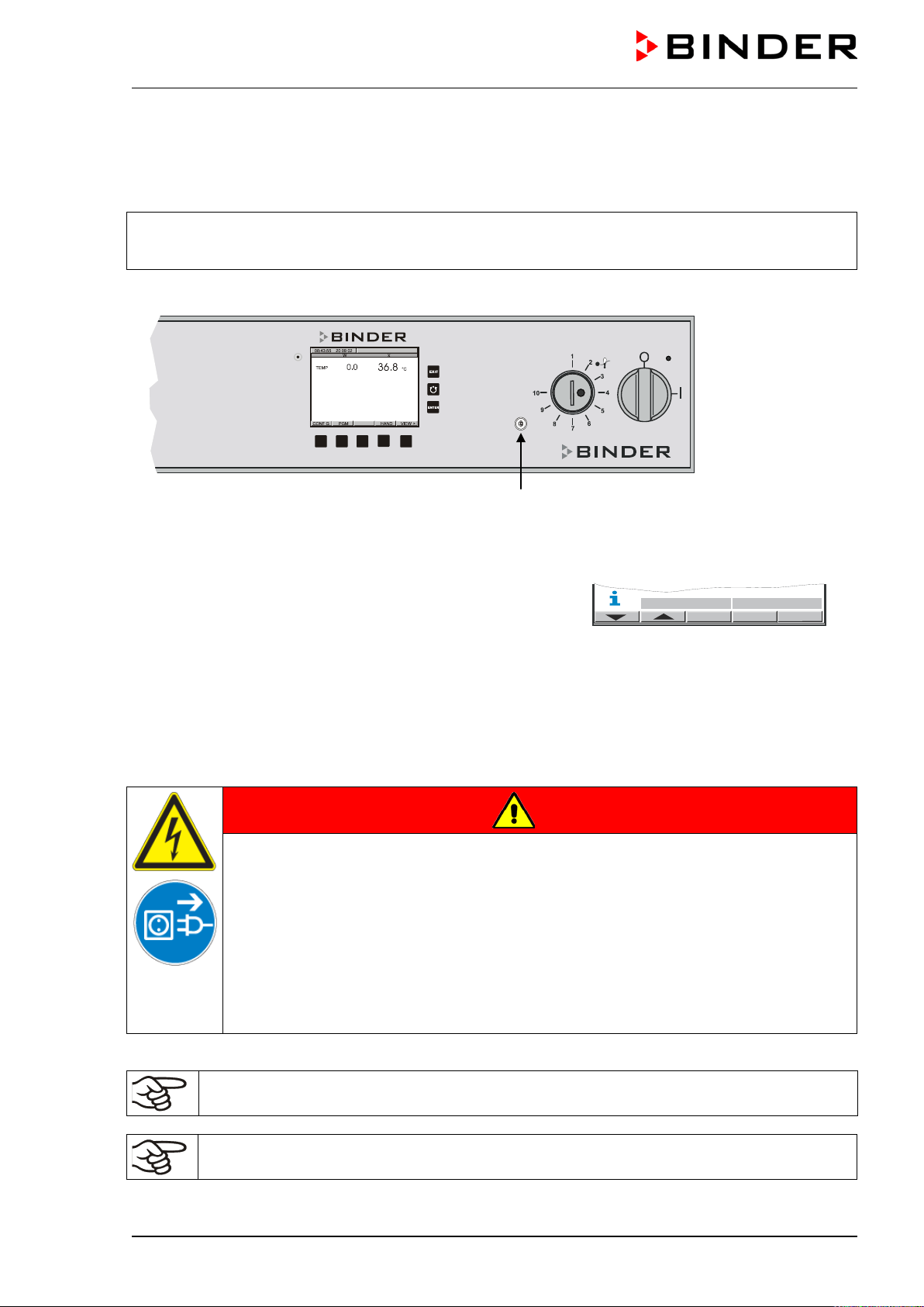
M (E2) 04/2019 page 44/71
11.10 Keyboard locking (option)
The keyboard of the MB1 controller can be locked and unlocked via the key switch (option). In the locked
position, no entries to the controller are possible.
• Locked keyboard: Switch in vertical position
• Unlocked keyboard: Switch in position to the right
You can remove the key only when the keyboard is locked.
Key switch
Figure 14: Keyboard locking (option)
If the keyboard is locked, the notification “KEY LOCK” is dis-
played on the controller MB1 di
splay next to a flashing blue
information symbol.
12. Maintenance, cleaning, and service
12.1 Maintenance intervals, service
DANGER
Electrical hazard.
Danger of death.
The chamber must NOT become wet during operation or maintenance work.
Do NOT remove the rear panel of the chamber.
Before conducting maintenance work, turn off the chamber at the main power switch
and disconnect the power plug.
Ensure all maintenance work is conducted by licensed electricians or experts author-
ized by BINDER.
Ensure regular maintenance work is performed at least once a year.
The warranty becomes void if maintenance work is conducted by non-authorized personnel.
Replace the door gasket only when cold. Otherwise, the door gasket may become damaged.
HAND
W
VIEW->
KEY LOCK
M (E2) 04/2019 page 45/71
We recommend taking out a maintenance agreement. Please consult BINDER Service.
BINDER telephone hotline: +49 (0) 7462 2005 555
BINDER fax hotline: +49 (0) 7462 2005 93555
BINDER e-mail hotline: service@binder-world.com
BINDER service hotline USA: +1 866 885 9794 or +1 631 224 4340 x3 (toll-free in the USA)
BINDER service hotline Asia Pacific: +852 390 705 04 or +852 390 705 03
BINDER service hotline Russia and CIS +7 495 988 15 16
BINDER Internet website http://www.binder-world.com
BINDER address BINDER GmbH, post office box 102,
78502 Tuttlingen, Germany
International customers, please contact your local BINDER distributor.
12.2 Cleaning and decontamination
Clean the chamber after each use to avoid potential corrosion damage by ingredients of the test material.
DANGER
Electrical hazard.
Danger of death.
Do NOT spill water or cleaning agents over the inner and outer surfaces.
Before cleaning, turn off the chamber at the main power switch and dis-
connect the power plug.
Completely dry the appliance before turning it on again.
12.2.1 Cleaning
Disconnect the chamber from the power supply before cleaning. Disconnect the power plug.
The interior of the chamber must be kept clean. Thoroughly remove any residues of test mate-
rial.
Wipe the surfaces with a moistened towel. In addition, you can use the following cleaning agents:
Exterior surfaces
inner chamber
racks
door gaskets
Standard commercial cleaning detergents free from acid or halides.
Alcohol based solutions.
We recommend using the neutral cleaning agent Art. No. 1002-0016.
Instrument panel Standard commercial cleaning detergents free from acid or halides.
We recommend using the neutral cleaning agent Art. No. 1002-0016.
Zinc coated hinge parts
rear chamber wall
Standard commercial cleaning detergents free from acid or halides.
Do NOT use a neutral cleaning agent on zinc coated surfaces.
Do not use cleaning agents that may cause a hazard due to reaction with components of the device or
the charging material. If there is doubt regarding the suitability of cleaning products, please contact
BINDER service.
M (E2) 04/2019 page 46/71
We recommend using the neutral cleaning agent Art. No. Art. Nr. 1002-0016 for a thorough
cleaning.
Any corrosive damage that may arise following use of other cleaning agents is excluded from
liability by BINDER GmbH.
Any corrosive damage caused by a lack of cleaning, is excluded from liability by BINDER
GmbH.
CAUTION
Danger of corrosion.
Damage to the chamber.
Do NOT use acidic or chlorine cleaning detergents.
Do NOT use a neutral cleaning agent on other kind of surfaces e.g., the zinc coated
hinge parts or the rear chamber wall.
For surface protection, perform cleaning as quickly as possible.
After cleaning completely remove cleaning agents from the surfaces with a moistened towel.
Let the chamber dry.
Soapsuds may contain chlorides and must therefore NOT be used for cleaning.
With every cleaning method, always use adequate personal safety controls.
Following cleaning, leave the chamber door open or remove the access port plugs (option).
The neutral cleaning agent may cause health problems in contact with skin and if ingested.
Follow the operating instructions and safety hints labeled on the bottle of the neutral clean-
ing agent.
Recommended precautions: To protect the eyes use sealed protective goggles. Suitable protective
gloves with full contact: butyl or nitrile rubber, penetration time >480 minutes.
CAUTION
Contact with skin, ingestion.
Skin and eye damage due to chemical burns.
Do not ingest. Keep away from food and beverages.
Do NOT empty into drains.
Wear protective gloves and goggles.
Avoid skin contact.
M (E2) 04/2019 page 47/71
12.2.2 Decontamination
The operator must ensure that proper decontamination is performed in case a contamination of the
chamber by hazardous substances has occurred.
Disconnect the chamber from the power supply prior to decontamination. Pull the power plug.
Do not use decontamination agents that may cause a hazard due to reaction with components of the
device or the charging material. If there is doubt regarding the suitability of cleaning products, please
contact BINDER service.
You can use the following disinfectants:
Inner chamber Standard commercial surface disinfectants free from acid or halides.
Alcohol based solutions.
We recommend using the disinfectant spray Art. No. 1002-0022.
For chemical disinfection, we recommend using the disinfectant spray Art. No. 1002-0022.
Any corrosive damage that may arise following use of other disinfectants is excluded from
liability by BINDER GmbH.
With every decontamination method, always use adequate personal safety controls.
In case of impurity of the interior with biological or chemical hazardous material, there are 3 possible pro-
cedures depending on the type of contamination and of the charging material.
(1) The chambers can be hot air sterilized at 190 °C for at least 30 minutes. All inflammable goods must
be removed from the interior before.
(2) Spray the inner chamber with an appropriate disinfectant.
Before start-up, the chamber must be absolute dry and ventilated, because explosive gases might
form during the decontamination process.
(3) If necessary, have strongly contaminated inner chamber parts removed by an engineer for cleaning,
or have them exchanged. Sterilize the inner chamber parts in a sterilizer or autoclave.
In case of eye contact, the disinfectant spray may cause eye damage due to chemical
burns. Follow the operating instructions and safety hints labeled on the bottle of the disin-
fectant spray.
Recommended precautions: To protect the eyes use sealed protective goggles.
CAUTION
Eye contact.
Eye damage due to chemical burns.
Do NOT empty into drains.
Wear protective goggles.
After using the disinfectant spray, allow the chamber to dry thoroughly, and aerate it sufficient-
ly.
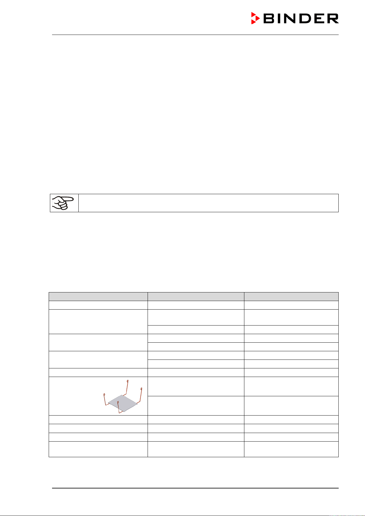
M (E2) 04/2019 page 48/71
12.3 Sending the chamber back to BINDER GmbH
If you return a BINDER product to us for repair or any other reason, we will only accept the product upon
presentation of an authorization number (RMA number) that has previously been issued to you. An
authorization number will be issued after receiving your complaint either in writing or by telephone prior
to your sending the BINDER product back to us. The authorization number will be issued following receipt
of the information below:
• BINDER product type and serial number
• Date of purchase
• Name and address of the dealer from which you bought the BINDER product
• Exact description of the defect or fault
• Complete address, contact person and availability of that person
• Exact location of the BINDER product in your facility
• A contamination clearance certificate (chap. 16) must be faxed in advance
The authorization number must be applied to the packaging in such a way that it can be easily recog-
nized or be recorded clearly in the delivery documents.
For security reasons we cannot accept a chamber delivery if it does not carry an authorization
number.
Return address:
BINDER GmbH
Abteilung Service
Gänsäcker 16
78502 Tuttlingen
Germany
13. Disposal
13.1 Disposal of the transport packing
Packing element
Material
Disposal
Straps to fix packing on pallet
Plastic
Plastic recycling
Wooden transport box (option)
with metal screws
Non-wood (compressed match-
wood, IPPC standard)
Wood recycling
Metal
Metal recycling
Pallet
with foamed plastic stuffing
Solid wood (IPPC standard)
Wood recycling
PE foam
Plastic recycling
Shipping box
with metal clamps
Cardboard
Paper recycling
Metal
Metal recycling
Top cover (size 720 only)
Cardboard
Paper recycling
Removal
aid (sizes 240
and 400 only)
Cardboard Paper recycling
Plastic Plastic recycling
Edge protection
Styropor
®
or PE foam
Plastic recycling
Protection of doors and racks
PE foam
Plastic recycling
Bag for operating manual
PE foil
Plastic recycling
Insulating air cushion foil (packing
of optional accessories)
PE foil Plastic recycling
If recycling is not possible, all packing parts can also be disposed of with normal waste.
M (E2) 04/2019 page 49/71
13.2 Decommissioning
Turn off the main power switch (2) and disconnect the chamber from the power supply (pull the power
plug).
Having turned off the chamber by the main power switch (2), the stored parameters remain
saved.
• With option inert gas connection (chap. 11.9): Close the inert gas supply and remove the gas connec-
tion.
WARNING
High concentration of inert gas.
Risk of death by suffocation.
Respect the relevant regulations for handling these gases.
When decommissioning the chamber, turn off the inert gas supply.
• Temporal decommissioning: See indications for appropriate storage, chap. 3.3.
• Final decommissioning: Dispose of the chamber as described in chap. 13.3 to 13.5.
13.3 Disposal of the chamber in the Federal Republic of Germany
According to Annex I of Directive 2012/19/EU of the European Parliament and of the Council on waste
electrical and electronic equipment (WEEE), BINDER devices are classified as “monitoring and control
instruments” (category 9) only intended for professional use“. They must not be disposed of at public
collecting points.
The chambers bear the symbol for the marking of electrical and electronic equipment man-
ufactured / placed on the market in the EU after 13 August 2005 and be disposed of in
separate collection according to Directive 2012/19/EU on waste electrical and electronic
equipment (WEEE) and German national law for electrical and electronic equipment (El-
ektro- und Elektronikgerätegesetz, ElektroG). WEEE marking: crossed-
out wheeled bin
with solid bar under. A significant part of the materials must be recycled in order to protect
the environment.
At the end of the device’s service life, have the chamber disposed of according to the German national
law for electrical and electronic equipment (Elektro- und Elektronikgerätegesetz, ElektroG from 20 Octo-
ber 2015, BGBl. I p. 1739) or contact BINDER service who will organize taking back and disposal of the
chamber according to the German national law for electrical and electronic equipment (Elektro- und El-
ektronikgerätegesetz, ElektroG from 20 October 2015, BGBl. I p. 1739).
CAUTION
Violation against existing law.
∅ Do NOT dispose of BINDER devices at public collecting points.
Have the device disposed of professionally at a recycling company which is certified
according to the German national law for electrical and electronic equipment (Elektro-
und Elektronikgerätegesetz, ElektroG from 20 October 2015, BGBl. I p. 1739).
or
Instruct BINDER Service to dispose of the device. The general terms of payment and
delivery of BINDER GmbH apply, which were valid at the time of purchasing the cham-
ber.
Certified companies disassemble waste (used) BINDER equipment in primary substances for recycling
according to Directive 2012/19/EU. The devices must be free from toxic, infectious or radioactive sub-
stances in order to eliminate any health hazards to the employees of the recycling companies.
M (E2) 04/2019 page 50/71
Prior to handing the chamber over to a recycling company, it is the user’s responsibility that it
is free from toxic, infectious or radioactive substances.
• Prior to disposal, clean all introduced or residual toxic substances from the chamber.
• Prior to disposal, disinfect the chamber from all sources of infection. Be aware that sources
of infection may also be located outside the inner chamber.
• If you cannot safely remove all toxic substances and sources of infection from the cham-
ber, dispose of it as special waste according to national law.
• Fill out the contamination clearance certificate (chap. 16) and enclose it with the chamber.
WARNING
Contamination of the chamber with toxic, infectious or radioactive substances.
Danger of intoxication.
Danger of infection.
∅ NEVER take a chamber contaminated with toxic substances or sources of infection for
recycling according to Directive 2012/19/EU.
Prior to disposal, remove all toxic substances and sources of infection from the cham-
ber.
A chamber from which all toxic substances or sources of infection cannot be safely
removed must be considered as “special” waste according to national law. Dispose of it
accordingly.
13.4 Disposal of the chamber in the member states of the EU except for the Fed-
eral Republic of Germany
According to Annex I of Directive 2012/19/EU of the European Parliament and of the Council on waste
electrical and electronic equipment (WEEE), BINDER devices are classified as “monitoring and control
instruments” (category 9) only intended for professional use“. They must not be disposed of at public
collecting points.
The chambers bear the symbol for the marking of electrical and electronic equipment
manufactured / placed on the market in the EC after 13 August 2005 and be disposed of in
separate collection according to the Directive 2012/19/EU on waste electrical and electron-
ic equipment (WEEE). WEEE marking: crossed-out wheeled bin with solid bar under.
At the end of the device’s service life, notify the distributor who sold you the device, who
will take back and dispose of the chamber according to the Directive 2012/19/EU on waste
electrical and electronic equipment (WEEE).
CAUTION
Violation against existing law.
∅ Do NOT dispose of BINDER devices at public collecting points.
Have the device disposed of professionally at a recycling company that is certified ac-
cording to conversion of the Directive 2012/19/EU into national law.
or
Instruct the distributor who sold you the device to dispose of it. The agreements apply
that were agreed with the distributor when purchasing the chamber (e.g. his general
terms of payment and delivery).
If your distributor is not able to take back and dispose of the chamber, please contact
BINDER service.
M (E2) 04/2019 page 51/71
Certified companies disassemble waste (used) BINDER equipment in primary substances for recycling
according to Directive 2012/19/EU. The devices must be free from toxic, infectious or radioactive sub-
stances in order to eliminate any health hazards to the employees of the recycling companies.
Prior to handing the chamber over to a recycling company, it is the user’s responsibility that it
is free from toxic, infectious or radioactive substances.
• Prior to disposal clean the chamber from all introduced or sticking toxic substances.
• Prior to disposal disinfect the chamber from all sources of infection. Be
aware that sources
of infection might be located as well outside the inner chamber.
• If you cannot safely free the chamber from toxic substances and sources of infection, dis-
pose of it as special waste according to national law.
• Fill out the contamination clearance certificate (chap. 16) and enclose it with the chamber.
WARNING
Contamination of the chamber with toxic, infectious or radioactive substances.
Danger of intoxication.
Danger of infection.
∅ NEVER take a chamber contaminated with toxic substances or sources of infection for
recycling according to Directive 2012/19/EU.
Prior to disposal, remove all toxic substances and sources of infection from the cham-
ber.
A chamber from which all toxic substances or sources of infection cannot be safely
removed must be considered as “special” waste according to national law. Dispose of it
accordingly.
13.5 Disposal of the chamber in non-member states of the EU
CAUTION
Alteration of the environment.
For final decommissioning and disposal of the chamber, please contact BINDER ser-
vice.
Follow the statutory regulations for appropriate, environmentally friendly disposal.
The main board of the chamber includes a lithium cell. Please dispose of it according to national regula-
tions.
M (E2) 04/2019 page 52/71
14. Troubleshooting
Fault description
Possible cause
Required measures
Heating
Chamber heating permanently,
set-point not maintained.
Controller defective.
Contact BINDER service.
Pt 100 sensor defective.
Semiconductor relay defective.
Controller not adjusted.
Calibrate and adjust controller.
Chamber doesn’t heat up.
Heating element defective.
Contact BINDER service.
Semiconductor relay defective
Chamber doesn’t heat up when
turned on.
Safety device class 2 responds.
Limit temperature reached.
Safety device class 2 (chap.
10.1) set too low.
Let the chamber cool down and hit
RESET button (3b). If appropriate,
select suitable limit value.
Safety controller (chap. 10.1)
defective.
Contact BINDER service.
Safety device class 3.1 (option)
responds.
Limit temperature reached.
Check setting of temperature set-
point and of safety device class 3.1.
If appropriate, select suitable limit
value.
Controller defective.
Contact BINDER service.
Safety device defective.
Controller
No entries to controller keypad
possible. Notification “KEY
LOCK” is displayed
Keyboard locking (option)
activated.
Unlock keyboard locking (chap.
11.10).
No access to menu “User set-
tings”“.
User code incorrect. Contact BINDER service.
Wrong temperature alarms, dis-
turbance of temperature accuracy
Temperature unit changed to
°F.
Set temperature unit to °C (chap.
6.4).
Chart recorder function: meas-
ured-value memory cleared, in-
formation lost.
New setting of storage rate.
Change the storage rate ONLY if the
previously registered data are no
longer required (chap. 7).
Controller does not attain set-
points entered in Manual Mode.
Button EXIT or AUTOMATIC
has been hit: Chamber is in
Idle Mode.
Change to Manual Mode (chap. 8).
Controller does not attain pro-
gram set-points.
Button EXIT or AUTOMATIC
has been hit: Chamber is in
Idle Mode.
Start the program again (chap. 9.7).
Program duration longer than
programmed.
Tolerances have been pro-
grammed.
For rapid transition phases, do NOT
program tolerance limits in order to
allow maximum heating, speed.
Program stops one section too
early.
Program line is incomplete.
When programming, define the end
value of the desired cycle by adding
an additional section with a section
time of at least one second.
Display flashing:
1999 or -1999 or 9999.
Sensor rupture between sen-
sor and controller
Contact BINDER service.
Short-circuit.
Initialization problem due to
turning on the chamber too
early.
Observe a delay time of approx. 30s
between turning the chamber Off
and On again.
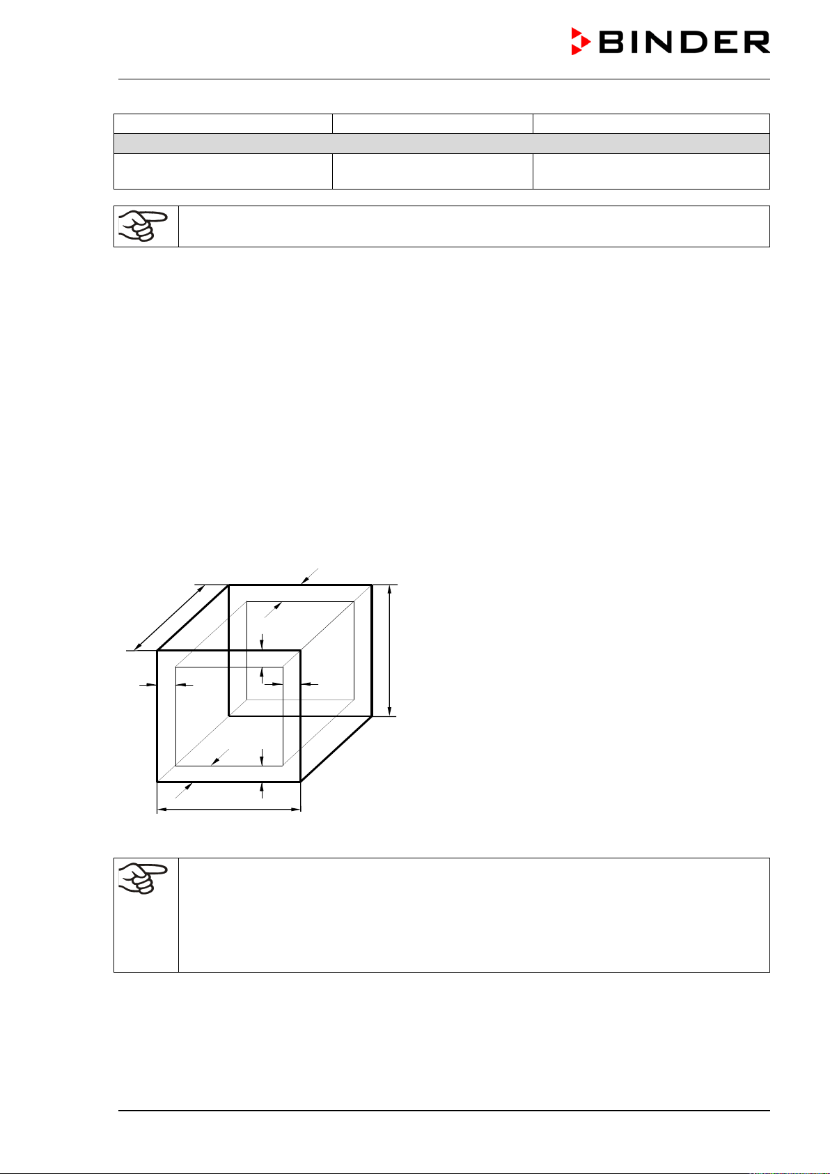
M (E2) 04/2019 page 53/71
Fault description
Possible cause
Required measures
Miscellaneous
Fan does not turn Fan speed set to 0%.
Set the fan speed to the desired
value.
Only qualified service personnel authorized by BINDER must perform repair.
Repaired chambers must comply with the BINDER quality standards.
15. Technical description
15.1 Factory calibration and adjustment
This chamber was calibrated and adjusted in the factory. Calibration and adjustment were performed
using standardized test instructions, according to the QM DIN EN ISO 9001 system applied by BINDER
(certified since December 1996 by TÜV CERT). All test equipment used is subject to the administration of
measurement and test equipment that is also constituent part of the BINDER QM DIN EN ISO 9001 sys-
tems. They are controlled and calibrated in relation to a DKD-Standard at regular intervals.
15.2 Definition of usable volume
The usable volume illustrated below is calculated as follows:
c
c
b
a
C
B
A
b
a
A, B, C = internal dimensions (W, H, D)
a, b, c = wall separation
a = 0.1*A
b = 0.1*B
c = 0.1*C
V
USE
= (A - 2 * a) * (B - 2 * b) * (C - 2 * c)
Figure 15: Determination of the useable volume
The technical data refers to the defined usable volume.
Do NOT place samples outside this usable volume.
Do NOT load this volume by more than half to enable sufficient airflow inside the chamber.
Do NOT divide the usable volume into separate parts with large area samples.
Do NOT place samples too close to each other in order to permit circulation between them
and thus obtain a homogenous distribution of temperature.
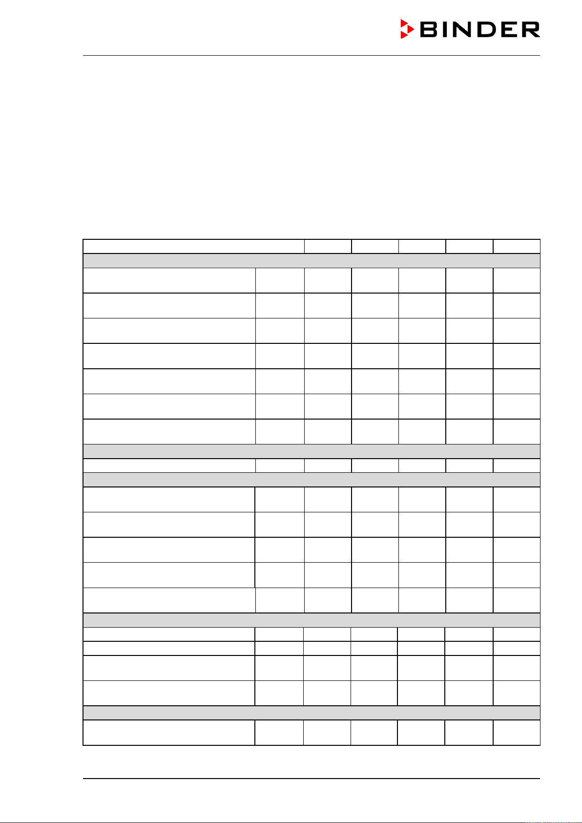
M (E2) 04/2019 page 54/71
15.3 Over current protection
Single-phase devices are protected by a miniature fuse against over current, accessible from the out-
side. The miniature fuse is located on the right side of the chamber above the strain relief of the power
cord. The fuse holder is equipped with a fuse clip 5mm x 20 mm. A fuse may be replaced only with a
substitute of the same ratings. Refer to the technical data of the respective device type.
Three-phase devices are equipped with internal fuses not accessible from outside. If these fuses are
blown, please inform an electronic engineer or BINDER service.
15.4 Technical data
Chamber size
53
115
240
400
720
Exterior dimensions
Width, net
mm
inch
635
25.00
835
32.87
1035
40.75
1235
48.62
1235
48.62
Height, gross (incl. feet/castors)
mm
inch
780
30.71
865
34.06
985
38.78
1185
46.65
1695
66.73
Depth, net
mm
inch
575
22.64
645
25.39
745
29.33
765
30.12
865
34.06
Depth, gross (incl. door handle, in-
strument panel, and exhaust duct)
mm
inch
680
26.77
750
29.53
850
33.46
870
34.25
970
38.19
Wall clearance rear (minimum)
mm
inch
100
3.94
100
3.94
100
3.94
100
3.94
100
3.94
Wall clearance side (minimum)
mm
inch
160
6.30
160
6.30
160
6.30
160
6.30
160
6.30
Exhaust duct, outer diameter
mm
inch
52
2.05
52
2.05
52
2.05
52
2.05
52
2.05
Doors
Number of doors
1
1
2
2
2
Interior dimensions
Width
mm
inch
400
15.75
600
23.62
800
31.50
1000
39.37
1000
39.37
Height
mm
inch
400
15.75
480
18.90
600
23.62
800
31.50
1200
47.24
Depth
mm
inch
340
13.39
410
16.14
510
20.08
510
20.08
610
24.02
Interior volume
l
cu.ft.
53
1.9
115
4.1
240
8.6
400
14.3
720
25.7
Steam space volume
l
cu.ft.
77
2.72
158
5.58
308
10.88
498
17.60
869
30.71
Racks
Quantity of racks (regular)
2
2
2
2
2
Quantity of racks (max.)
5
6
7
10
16
Maximum load per rack
Kg
lbs
15
33
20
44
30
66
35
77
45
99
Maximum permitted total load
Kg
lbs
40
88
50
110
70
155
90
199
120
265
Weight
Weight (empty)
Kg
lbs
61
135
89
196
131
289
173
382
203
448
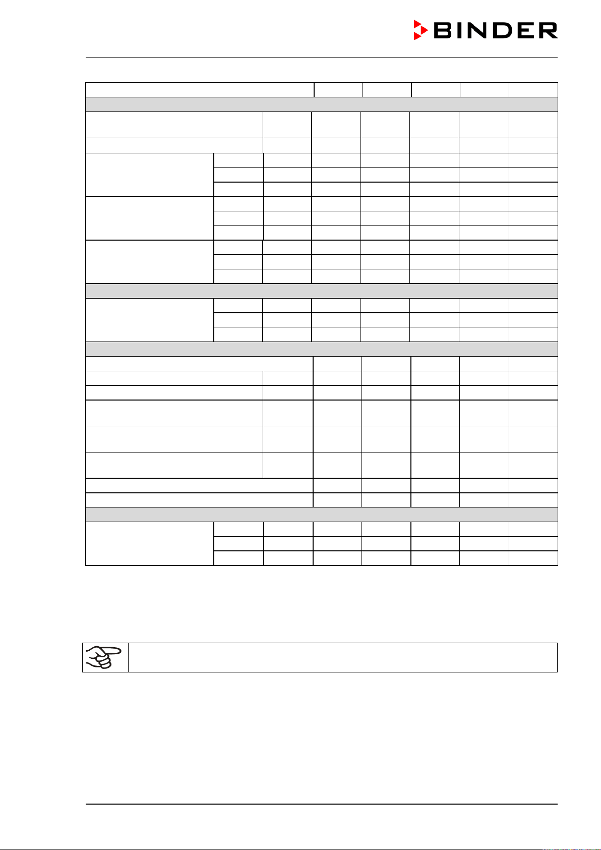
M (E2) 04/2019 page 55/71
Chamber size
53
115
240
400
720
Temperature data
Temperature range, 5 °C above ambi-
ent up to
°C
°F
300
572
300
572
300
572
300
572
300
572
Temperature fluctuation
≤
± K
0.3
0.3
0.3
0.3
0.3
Temperature uniformity
(variation)
at 70 °C
± K
0.5
0.6
0.8
0.7
0.7
at 150 °C
± K
1.3
1.5
1.5
1.5
1.9
at 300 °C
± K
2.8
2.8
2.8
5
4.6
Heating up time
to 70 °C
min
5
5
6
6
7
to 150 °C
min
15
16
19
18
21
to 250 °C
min
35
36
42
44
51
Recovery time after door
was opened for 30 sec 2)
to 70 °C
min
1
1
1
1
1
to 150 °C
min
3
3
3
3
3
to 300 °C
min
5
5
5
5
5
Air change data
Air change (air flap open)
at 70 °C
x/h
180
87
57
51
33
at 150 °C
x/h
192
96
60
54
36
at 300 °C
x/h
160
78
54
48
29
Electrical data
IP system of protection acc. to EN 60529
20
20
20
20
20
Nominal voltage (±10 %) 50/60 Hz
V
230 1N~
230 1N~
230 1N~
400 3N~
400 3N~
Nominal power
kW
1.20
1.60
2.70
3.40
5.00
Power plug
shock
proof plug
shock
proof plug
shock
proof plug
CEE plug
5 poles
CEE plug
5 poles
Chamber fuse 5x20 mm / 250V / time-
lag T
Amp
10
external
10
external
16
external
--- ---
Over-current release category B, 3
poles
Amp --- --- ---
16
internal
16
internal
Installation category acc. to IEC 61010-1
II
II
II
II
II
Pollution degree acc. to IEC 61010-1
2
2
2
2
2
Environment-specific data
Energy consumption
at 70 °C
Wh/h
145
230
370
520
570
at 150 °C
Wh/h
300
544
850
1200
1320
at 300 °C
Wh/h
720
1100
1400
2340
2600
All technical data is specified for unloaded chambers with standard equipment at an ambient temperature
of +25 °C / 77 °F and a power supply voltage fluctuation of ±10. Technical data is determined in accord-
ance to BINDER Factory Standard Part 1:2015 following DIN 12880:2007.
All indications are average values, typical for chambers produced in series. We reserve the right
to change technical specifications at any time.
If the chamber is fully loaded, the specified heating up times may vary according to the load.
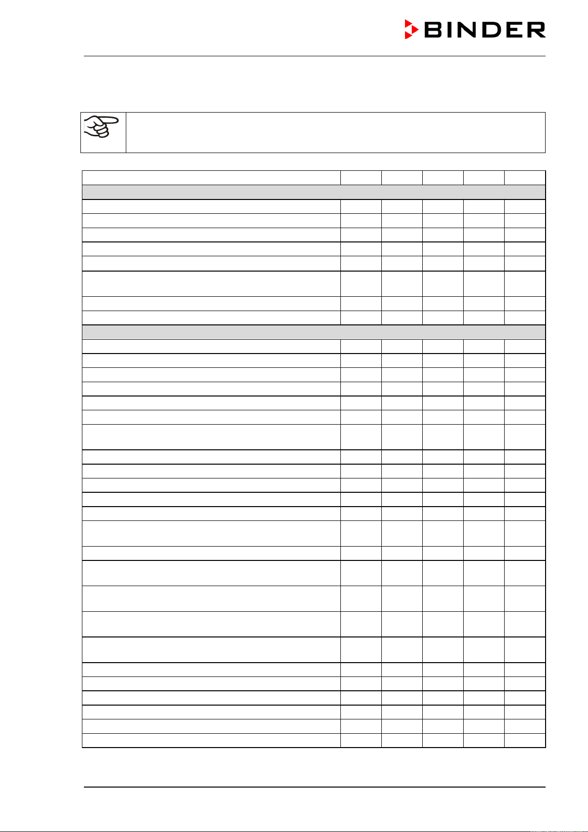
M (E2) 04/2019 page 56/71
15.5 Equipment and options (extract)
To operate the chamber, use only original BINDER accessories or accessories / components
from third-party suppliers authorized by BINDER. The user is responsible for any risk arising
from using unauthorized accessories.
Chamber Size
53
115
240
400
720
Regular equipment
Microprocessor display program controller
Communication interface RS 422
Program controlled air flap
Programmable automatic ventilation
Exhaust duct
∅
50 mm
Temperature safety device class 2 acc. to DIN
12880:2007 with optical temperature alarm
Four castors (2 lockable)
--
--
--
--
2 racks, chrome-plated
Options / accessories
Access ports, various diameters, with silicone plug
Rack, chrome-plated or stainless steel
Perforated rack ,stainless steel
Securing elements for additional fastening of racks (4 pc.)
Reinforced rack with rack lockings
--
--
Reinforced inner chamber with 2 reinforced racks
--
--
Temperature safety device class 3.1 acc. to DIN
12880:2007, available via BINDER Individual
Door(s) with window and interior lighting
Keyboard locking
Lockable door
FKM door gasket (temperature resistant up to 200 °C)
HEPA Fresh air filter, class H 14 (DIN EN 1822)
Measurement protocol of air change rate acc. to ASTM D
5374
Mostly gas-tight version
--
--
--
Inert gas connection (inlet and outlet) with mostly gas-
tight
version
-- -- --
Additional flexible Pt100 temperature sensor with external
connection
Additional measuring channel for digital object tempera-
ture display with flexible Pt100 temperature sensor
Analog output 4-20 mA for temperature with 6 pole DIN
socket, DIN plug included
Data Logger Kit T 350
Temperature calibration including certificate
Spatial temperature measurement including certificate
Qualification folder
Base on castors
--
--
--
Sturdy trolley, castors with locking brakes
--
Legend: Standard equipment Optional -- Not available
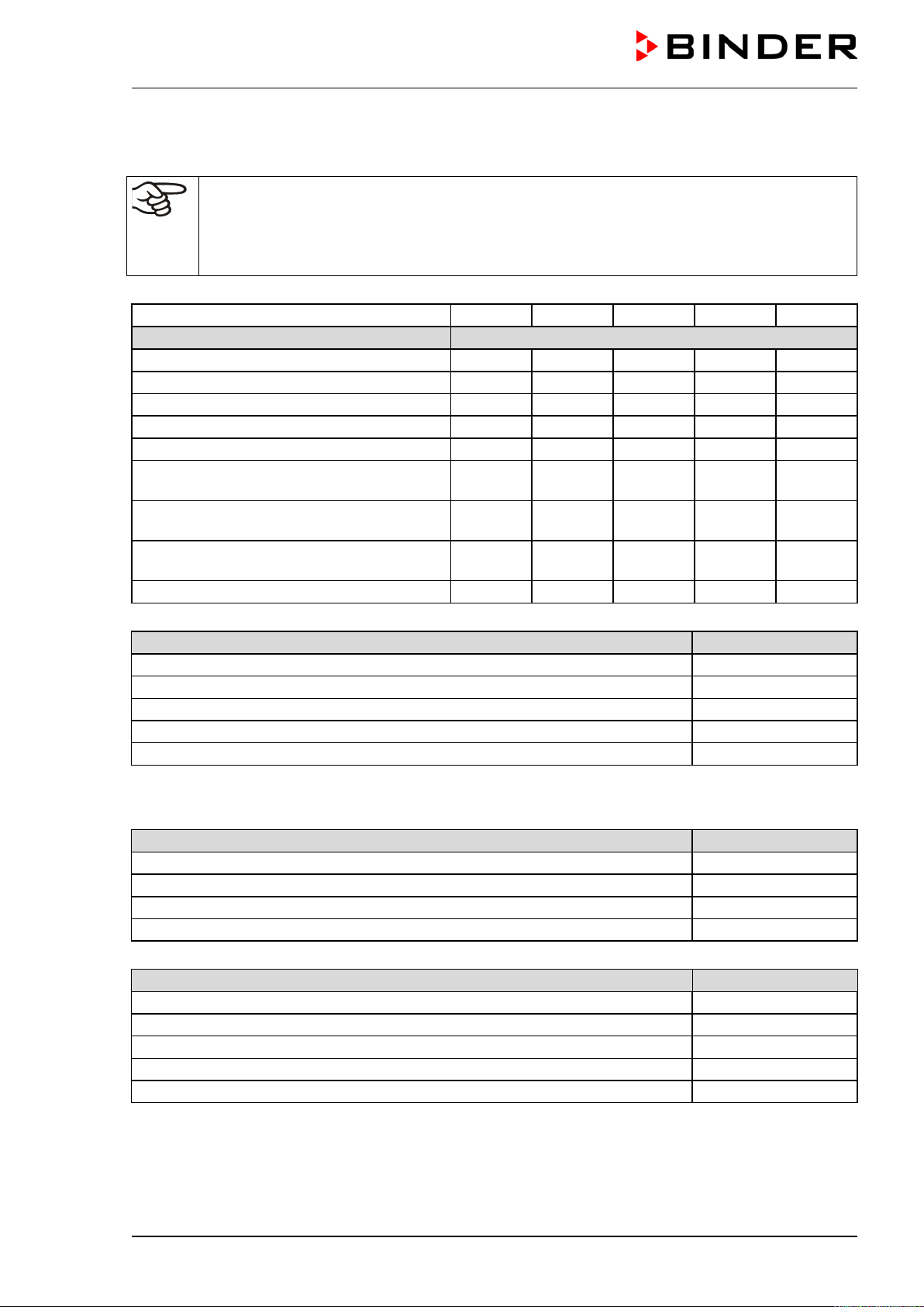
M (E2) 04/2019 page 57/71
15.6 Accessories and spare parts (extract)
BINDER GmbH is responsible for the safety features of the chamber only, provided skilled
electricians or qualified personnel authorized by BINDER perform all maintenance and repair,
and if components relating to chamber safety are replaced in the event of failure with original
spare parts. The user is responsible for any risks arising from using unauthorized accessories/
components.
Chamber size
53
115
240
400
720
Description
Art. No.
Rack, chrome-plated
6004-0002
6004-0003
6004-0004
6004-0005
6004-0006
Rack, stainless steel
6004-0007
6004-0008
6004-0009
6004-0011
6004-0010
Perforated rack, stainless steel
6004-0029
6004-0030
6004-0031
6004-0032
6004-0033
Reinforced rack with rack lockings
--
--
8012-0345
8012-0346
8012-0374
Door gasket silicone
6005-0095
6005-0096
6005-0097
6005-0069
6005-0099
Door gasket made of FKM (temperature re-
sistant up to 200 °C)
8012-0494
8012-0495
8012-0496
8012-0497
8012-0498
Chamber fuse 5x20mm 250V 10A time-lag
(T)
5006-0079
5006-0079
-- -- --
Chamber fuse 5x20mm 250V 16A time-lag
(T)
-- -- 5006-0103
-- --
Sturdy trolley, castors with locking brakes
9051-0018
9051-0018
9051-0019
9051-0019
--
Description
Art. No.
HEPA Fresh air filter, class EU 14H 14 (DIN EN 1822)
8012-0222
Data logger Kit T350
8012-0714
Data logger software, including converter-cable
8012-0821
Rack lockings (4 pieces)
8012-0531
Neutral cleaning agent, 1 kg
1002-0016
For information on components not listed here, please contact BINDER Service.
Validation service
Art. No.
Qualification folder IQ-OQ
8012-0862
Qualification folder IQ-OQ-PQ
8012-0950
Execution of IQ-OQ
DL410200
Execution of IQ-OQ-PQ
DL440500
Calibration service
Art. No.
Calibration of temperature including certificate (1 measuring point)
DL300101
Spatial temperature measurement including certificate (9 measuring points)
DL300109
Spatial temperature measurement including certificate (18 measuring points)
DL300118
Spatial temperature measurement including certificate (27 measuring points)
DL300127
Measurement of air ventilation acc. to ASTM D 5374, including certificate
DL330000
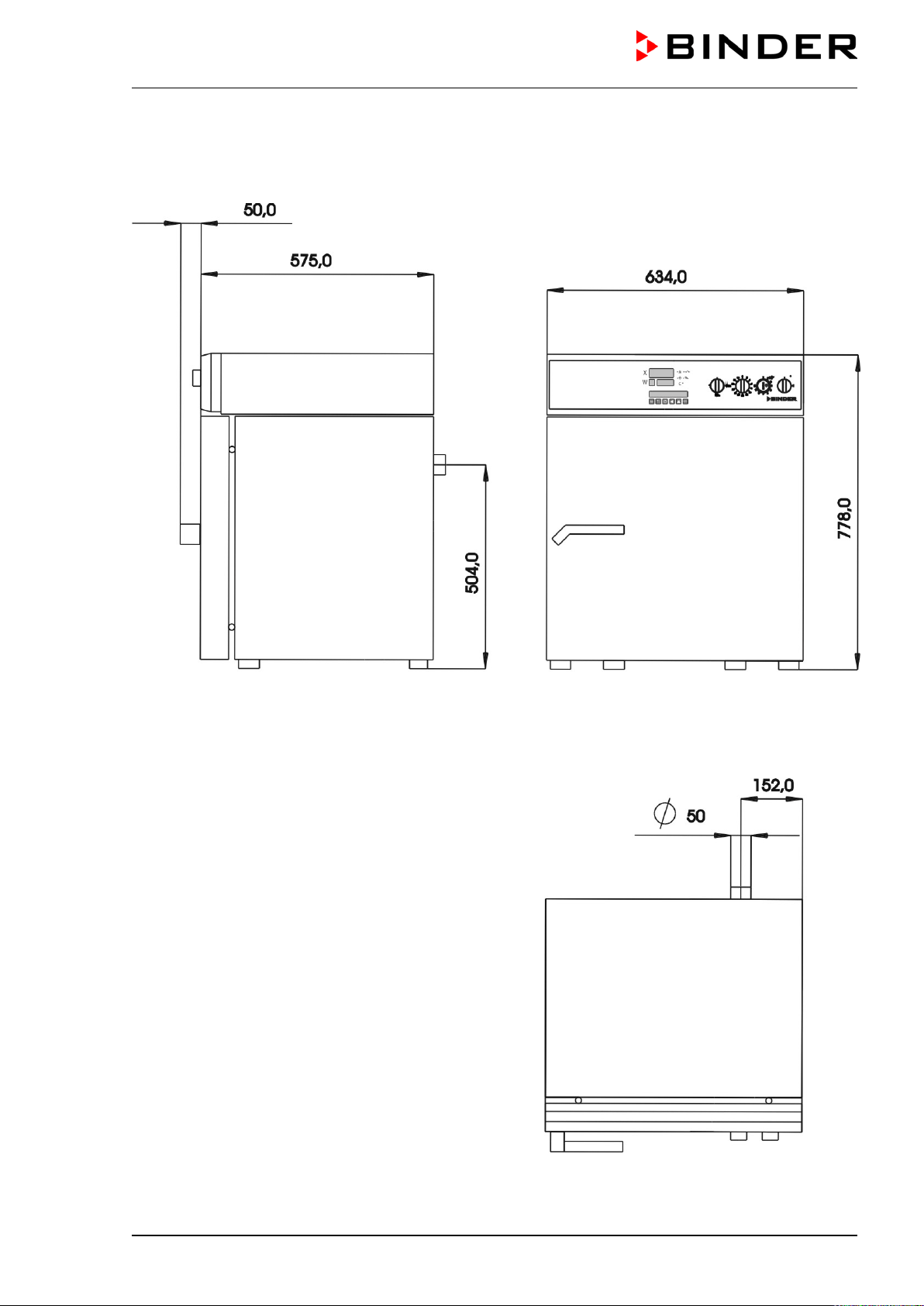
M (E2) 04/2019 page 58/71
15.7 Dimensions M 53
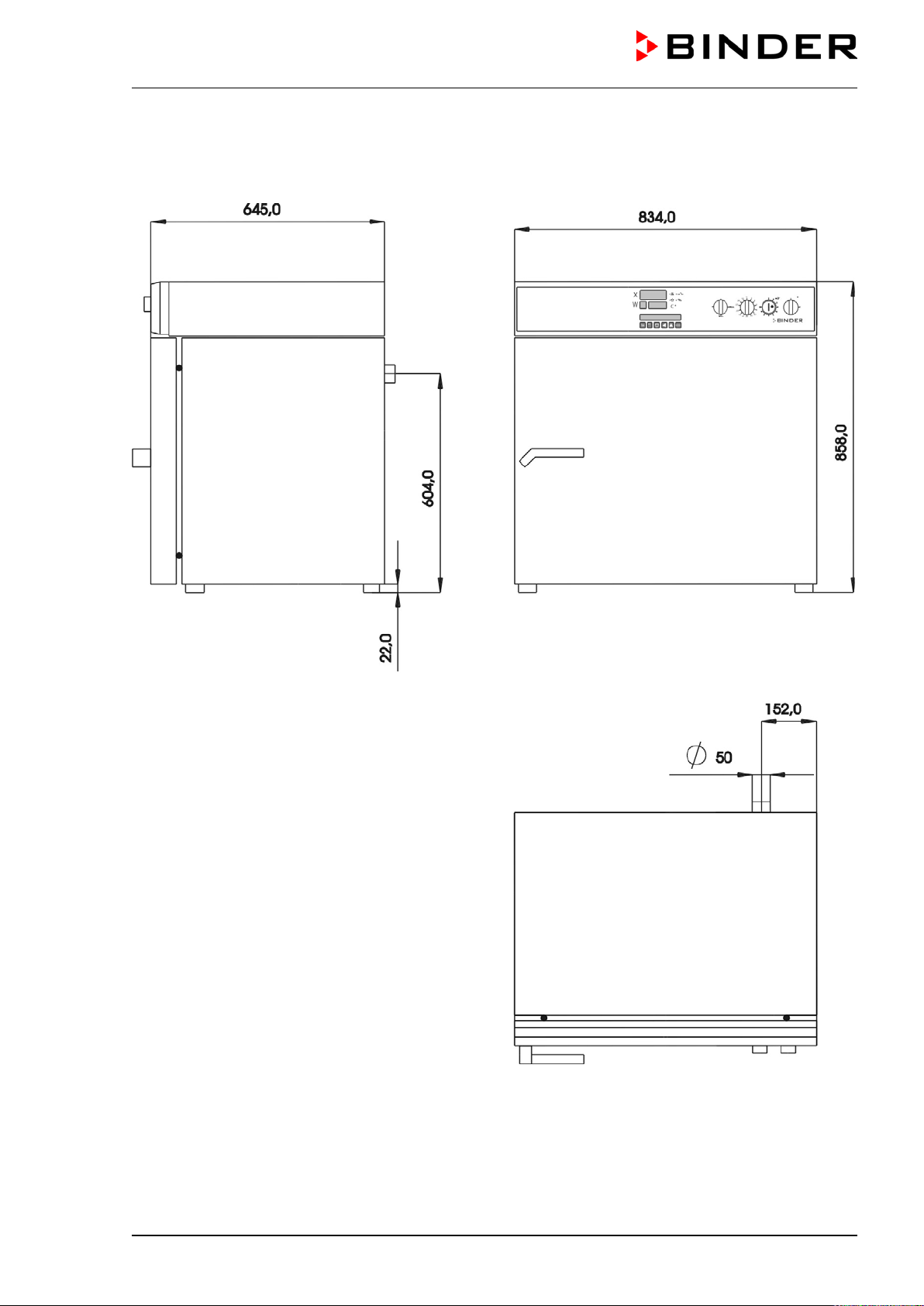
M (E2) 04/2019 page 59/71
15.8 Dimensions M 115
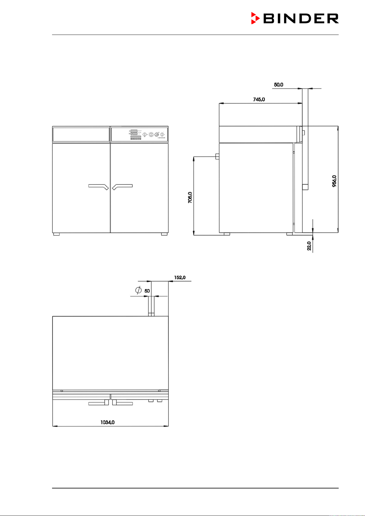
M (E2) 04/2019 page 60/71
15.9 Dimensions M 240
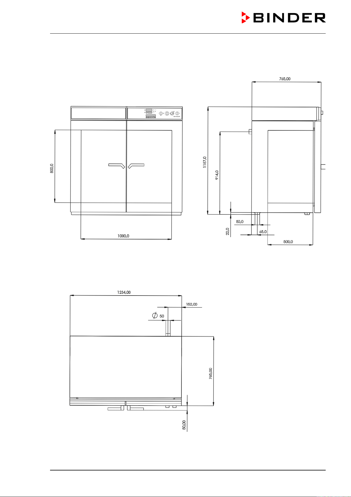
M (E2) 04/2019 page 61/71
15.10 Dimensions M 400
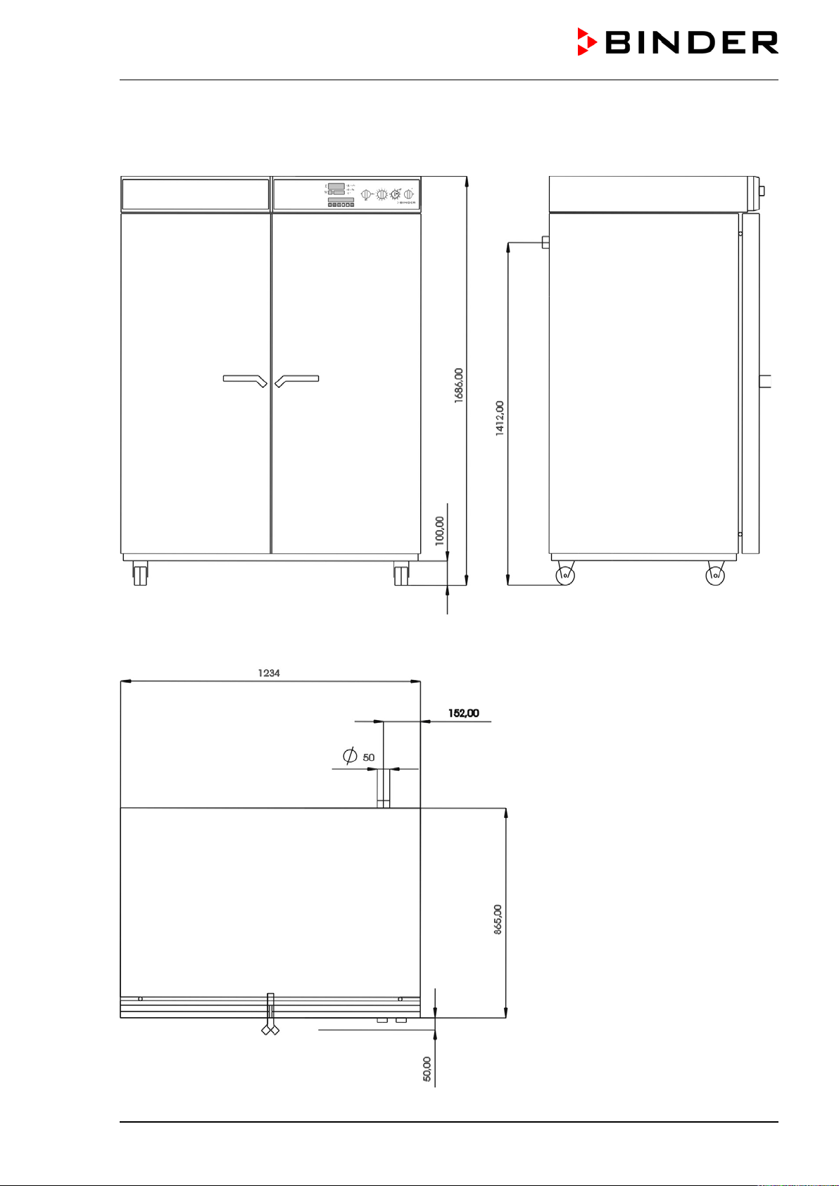
M (E2) 04/2019 page 62/71
15.11 Dimensions M 720
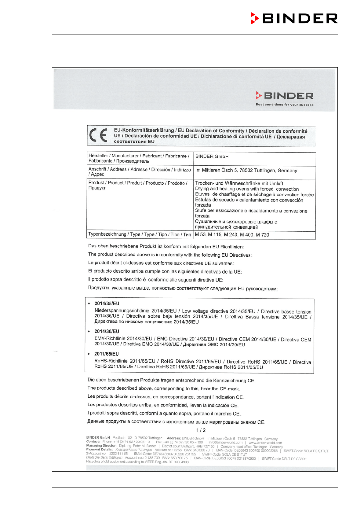
M (E2) 04/2019 page 63/71
16. EU Declaration of Conformity
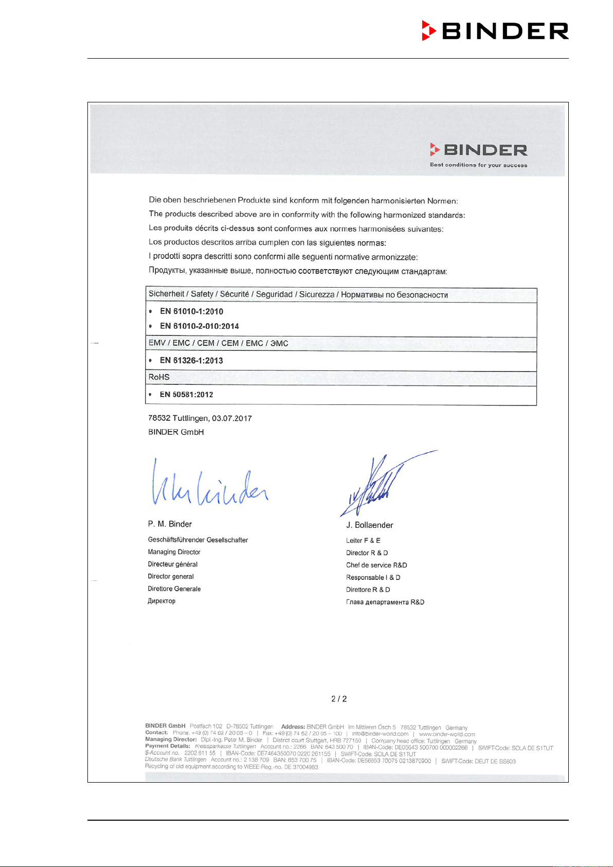
M (E2) 04/2019 page 64/71
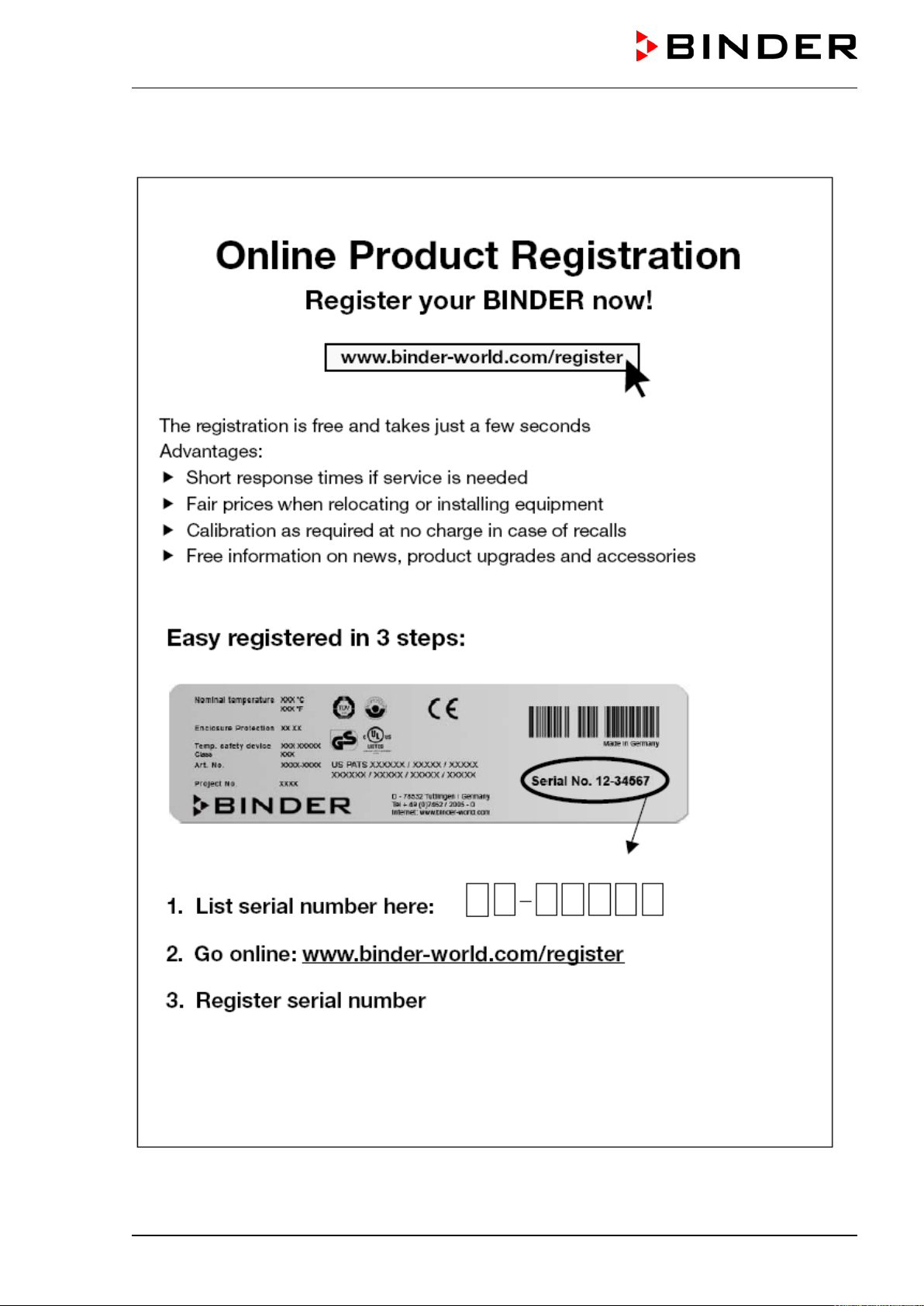
M (E2) 04/2019 page 65/71
17. Product registration
M (E2) 04/2019 page 66/71
18. Contamination clearance certificate
Unbedenklichkeitsbescheinigung
18.1 For chambers located outside the USA and Canada
Declaration regarding safety and health
Erklärung zur Sicherheit and gesundheitlichen Unbedenklichkeit
The German Ordinance on Hazardous Substances (GefStofV), and the regulations regarding safety at
the workplace, require that this form be filled out for all products that are returned to us, so that the safety
and the health of our employees can be guaranteed.
Die Sicherheit und Gesundheit unserer Mitarbeiter, die Gefahrstoffverordnung GefStofV und die Vorschriften zur
Sicherheit am Arbeitsplatz machen es erforderlich, dass dieses Formblatt für alle Produkte, die an uns zurückge-
schickt wird.
Note: A repair is not possible without a completely filled out form.
Ohne Vorliegen des vollständig ausgefüllten Formblattes ist eine Reparatur nicht möglich.
• A completely filled out form must be transmitted via Fax (+49 (0) 7462 2005 93555) or by letter in
advance, so that this information is available before the equipment/component part arrives. A second
copy of this form must accompany the equipment/component part. In addition, the carrier should be
notified.
Eine vollständig ausgefüllte Kopie dieses Formblattes soll per Telefax (Nr. +49 (0) 7462 2005 93555) oder Brief
vorab an uns gesandt werden, so dass die Information vorliegt, bevor das Gerät/Bauteil eintrifft. Eine weitere Ko-
pie soll dem Gerät/Bauteil beigefügt sein. Ggf. ist auch die Spedition zu informieren.
• Incomplete information or non-conformity with this procedure will inevitably lead to substantial delays
in processing. Please understand the reason for this measure, which lies outside our area of influence
and will help us to speed up this procedure.
Unvollständige Angaben oder Nichteinhalten dieses Ablaufs führen zwangsläufig zu beträchtlichen Verzögerun-
gen in der Abwicklung. Bitte haben Sie Verständnis für Maßnahmen, die außerhalb unserer Einflussmöglichkeiten
liegen und helfen Sie mit, den Ablauf beschleunigen.
• Please print and fill out this form completely.
Bitte unbedingt vollständig ausfüllen!
1. Unit/ component part / type: /
Gerät / Bauteil / Typ:
2. Serial No./
Serien-Nr.:
3. Details about utilized substances / biological substances /
Einzelheiten über die eingesetzten
Substanzen/biologische Materialien:
3.1 Designations / Bezeichnungen:
a) ____________________________________________________________________________
b) ____________________________________________________________________________
c) ____________________________________________________________________________
3.2 Safety measures required for handling these substances / Vorsichtsmaßnahmen beim Umgang
mit diesen Stoffen:
a) ____________________________________________________________________________
b) ____________________________________________________________________________
c) ____________________________________________________________________________

M (E2) 04/2019 page 67/71
3.3 Measures to be taken in case of skin contact or release into the atmosphere / Maßnahmen
bei Personenkontakt oder Freisetzung:
a) ____________________________________________________________________________
b) ____________________________________________________________________________
c) ____________________________________________________________________________
d) ____________________________________________________________________________
3.4 Other important information that must be taken into account / Weitere zu beachtende und
wichtige Informationen:
a) ____________________________________________________________________________
b) ____________________________________________________________________________
c) ____________________________________________________________________________
4. Declaration on the risk of these substances (please checkmark the applicable items) /
Erklärung zur Gefährlichkeit der Stoffe (bitte Zutreffendes ankreuzen) :
4.1 For non toxic, non radioactive, biologically harmless materials / für nicht giftige, nicht radio-
aktive, biologisch ungefährliche Stoffe:
We hereby guarantee that the above-mentioned unit / component part… /
Wir versichern, dass o.g.
Gerät/Bauteil...
Has not been exposed to or contains any toxic or otherwise hazardous substances /
weder giftige noch
sonstige gefährliche Stoffe enthält oder solche anhaften.
That eventually generated reaction products are non-toxic and also do not represent a hazard /
auch
evtl. entstandene Reaktionsprodukte weder giftig sind noch sonst eine Gefährdung darstellen.
Eventual residues of hazardous substances have been removed /
evtl. Rückstände von Gefahrstoffen
entfernt wurden.
4.2 For toxic, radioactive, biologically harmful or hazardous substances, or any other hazard-
ous materials /
für giftige, radioaktive, biologisch bedenkliche bzw. gefährliche Stoffe oder
anderweitig gefährliche Stoffe.
We hereby guarantee that … /
Wir versichern, dass …
The hazardous substances, which have come into contact with the above-mentioned equip-
ment/component part, have been completely listed under item 3.1 and that all information in this re-
gard is complete /
die gefährlichen Stoffe, die mit dem o.g. Gerät/Bauteil in Kontakt kamen, in 3.1 aufgelistet
sind und alle Angaben vollständig sind.
That the unit /component part has not been in contact with radioactivity /
das Gerät/Bauteil nicht mit Ra-
dioaktivität in Berührung kam
5. Kind of transport / transporter / Transportweg/Spediteur:
Transport by (means and name of transport company, etc.) Versendung durch (Name Spediteur o.ä.)
________________________________________________________________________________
Date of dispatch to BINDER GmbH /
Tag der Absendung an BINDER GmbH:
___________________________________________________________________________________
M (E2) 04/2019 page 68/71
We hereby declare that the following measures have been taken / Wir erklären, dass folgende
Maßnahmen getroffen wurden:
Hazardous substances were removed from the unit including component parts
, so that no hazard
exists for any person iin the handling or repair of these items / das Gerät/Bauteil wurde von Gefahrstoffen
befreit, so dass bei Handhabung/Reparaturen für die betreffenden Person keinerlei Gefährdung besteht
The unit was securely packaged and properly identified /
das Gerät wurde sicher verpackt und vollständig
gekennzeichnet.
Information about the hazardousness of the shipment (if required) has been provided to the transpor-
ter /
der Spediteur wurde (falls vorgeschrieben) über die Gefährlichkeit der Sendung informiert.
We hereby commit ourselves and guarantee that we will indemnify BINDER GmbH for all damages that
are a consequence of incomplete or in
correct information provided by us, and that we will exempt
BINDER GmbH from eventual damage claims by third parties./
Wir versichern, dass wir gegenüber BINDER
für jeden Schaden, der durch unvollständige und unrichtige Angaben entsteht, haften und BINDER
gegen eventuell
entstehende Schadenansprüche Dritter freistellen.
We are aware that, in accordance with Article 823 of the German Civil Code (BGB), we are directly liable
with regard to third parties, in this instance especially the employees of BINDER G
mbH, who have been
entrusted with the handling / repair of the unit / component. / Es ist uns bekannt, dass wir gegenüber Dritten –
hier insbesondere mit der Handhabung/Reparatur des Geräts/des Bauteils betraute Mitarbeiter der Firma BINDER -
gemäß §823 BGB direkt haften
Name: ______________________________________________________________________
Position / Title: _____________________________________________________________________
Date /
Datum: ______________________________________________________________________
Signature /
Unterschrift: ______________________________________________________________
Company stamp /
Firmenstempel:
Equipment that is returned to the factory for repair must be accompanied by a completely filled
out contamination clearance certificate. For service and maintenance on site, such a contami-
nation clearance certificate must be submitted to the service technician before the start of any
work. No repair or maintenance of the equipment is possible, without a properly filled out con-
tamination clearance certificate.

M (E2) 04/2019 page 69/71
18.2 For chambers located in the USA and Canada
Product Return Authorization Request
Please complete this form and the Customer Decontamination Declaration (next 2 pages) and attach the
required pictures. E-mail to: IDL_SalesOrderProcessing_USA@binder-world.com
After we have received and reviewed the complete information we will decide on the issue of a RMA
number. Please be aware that size specifications, voltage specifications as well as performance specifi-
cations are available on the internet at
www.binder-world.us at any time.
Take notice of shipping laws and regulations.
Please fill:
Reason for return request Duplicate order
Duplicate shipment
Demo Page one completed by sales
Power Plug / Voltage 115V / 230 V / 208 V / 240V
Size does not fit space
Transport Damage Shock watch tripped? (pictures)
Other (specify below)
_____________________
Is there a replacement PO? Yes No
If yes -> PO #
If yes -> Date PO placed
Purchase order number
BINDER model number
BINDER serial number
Date unit was received
Was the unit unboxed? Yes No
Was the unit plugged in? Yes No
Was the unit in operation? Yes No
Pictures of unit attached?
Pictures of Packaging at-
tached?
Yes No
Yes No
Pictures have to be attached!
Customer Contact Information Distributor Contact Information
Name
Company
Address
Phone
E-mail
M (E2) 04/2019 page 70/71
Customer (End User) Decontamination Declaration
Health and Hazard Safety declaration
To protect the health of our employees and the safety at the workplace, we require that this form is com-
pleted by the user for all products and parts that are returned to us. (Distributors or Service Organizations
cannot sign this form)
NO RMA number will be issued without a completed form. Products or parts returned to our
NY warehouse without a RMA number will be refused at the dock.
A second copy of the completed form must be attached to the outside of the shipping box.
1. Unit/ component part / type
:
2. Serial No.
3. List any exposure to hazardous liquids, gasses or substances and radioactive material
3.1 List with MSDS sheets attached where available or needed
(if there is not enough space available below, please attach a page):
a) ____________________________________________________________________________
b) ____________________________________________________________________________
c) ____________________________________________________________________________
3.2 Safety measures required for handling the list under 3.1
a) ____________________________________________________________________________
b) ____________________________________________________________________________
c) ____________________________________________________________________________
3.3 Measures to be taken in case of skin contact or release into the atmosphere
:
a) ____________________________________________________________________________
b) ____________________________________________________________________________
c) ____________________________________________________________________________
d) ____________________________________________________________________________
3.4 Other important information that must be considered:
a) ____________________________________________________________________________
b) ____________________________________________________________________________
c) ____________________________________________________________________________
M (E2) 04/2019 page 71/71
4. Declaration of Decontamination
For toxic, radioactive, biologically and chemically harmful or hazardous substances, or any other
hazardous materials
.
We hereby guarantee that
4.1 Any hazardous substances, which have come into contact with the above-mentioned equipment /
component part, have been completely listed under item 3.1 and that all information in this regard is
complete
.
4.2 That the unit /component part has not been in contact with radioactivity
4.3
Any Hazardous substances were removed from the unit / component part, so that no hazard exists
for a persons in the shipping, handling or repair of these returned unit
4.4
The unit was securely packaged in the original undamaged packaging and properly identified on
the outside of the packaging material with the unit designation, the RMA number and a copy of this
declaration.
4.5 Shipping laws and regulations have not been violated.
I hereby commit and guarantee that we will indemnify BINDER Inc. for all damages that are a
consequence of incomplete or incorrect information provided by us, and that we will indemnify
and hold harmless BINDER Inc. from eventual damage claims by third parties.
Name: _______________________________________________________________________
Position: _______________________________________________________________________
Company: _______________________________________________________________________
Address: _______________________________________________________________________
Phone #: _______________________________________________________________________
Email: _______________________________________________________________________
Date: _______________________________________________________________________
Signature: _______________________________________________________________________
Equipment returned to the NY warehouse for repair must be accompanied by a completed
customer decontamination declaration. For service and maintenance works on site, such a
customer decontamination declaration must be submitted to the service technician before the
start of work. No repair or maintenance of the equipment is possible without a completed form.